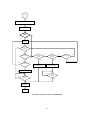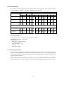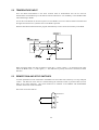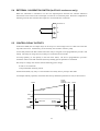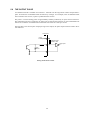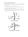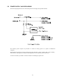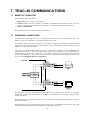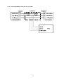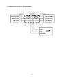
1
OPERATING MANUAL FOR MODEL Trac-40 ELECTRONIC TRUCK REGISTER Contrec Manufacturing Limited Riverside, Canal Road, Sowerby Bridge West Yorkshire HX6 2AY United Kingdom Email [email protected] Website www.contrec.co.uk REVISIONS Issue Number PRELIMINARY 1.0 2.0 3.0 4.0 5.0 6.0 Date 01-06-1999 03-03-2000 24-03-2000 09-10-2000 02-07-2002 08-02-2006 20-03-2014 Approved CONTENTS 1. Overview 1.1 Part Number Designations 1 2 2. Specification 3 3. Operation 3.1 Front Panel Operation 3.1.1 Modes of Operation 3.1.2 Displayed Information 3.1.3 Changing Batch Quantity or Density 3.2 Non Preset Mode 3.2.1 Starting a Delivery 3.2.2 End of Delivery 3.2.3 Auto Reset Flow Chart 1: Operation of Trac-40 in Non Preset Mode 3.3 Preset Mode 3.3.1 Starting a Batch 3.3.2 End of Batch 3.3.3 End of Batch Signal 3.3.4 Batching on Gross or Net Total Flow Chart 2: Operation of Trac-40 in Preset Mode 3.4 Printing a Ticket 3.5 Signal Timeout 3.6 The 3 Minute Timer 3.7 Frequency Cutoff 3.8 Clearable Minimum Total 3.9 Overflow/Theft Detection 3.10 Loss of Power 5 6 6 6 6 7 7 7 7 8 9 9 9 9 9 10 11 11 11 12 12 12 12 4. Calibration 4.1 Programming the Setup Parameters 4.2 Entering the Batch Parameters 4.3 Entering RS232 Parameters 4.4 Checking the Input Signal 13 14 17 18 20 5. Input Circuits 5.1 Flow Inputs 5.1.1 Frequency Inputs 5.1.2 Switch Settings 5.1.3 Powering of Sensors 5.2 Temperature Input 26 5.3 Remote Run and Stop Switches 5.4 External Calibration Switch (for Ex 410 enclosures only) 5.5 Control Relay Outputs 5.6 The Output Pulse 5.7 End of Delivery and Flow Alarm 5.8 Power Supply and Grounding 21 21 21 22 22 26 27 27 28 29 30 6. Technical Description 6.1 Single and Quadrature Inputs 6.2 Calculation of Rate and Total 6.3 Non-Linearity Correction 6.4 Filtering 6.5 Temperature Compensation 6.5.1 Temperature Input 6.5.2 Volume Correction for General Liquids 6.5.3 Compensation for Petroleum Liquids 6.5.4 Compensation for Liquefied Petroleum Gas (LPG) 6.5.5 Compensation for Anhydrous Ammonia 31 31 31 32 33 34 34 35 36 37 37 7. Trac-40 Communications 7.1 Modes of Operation 7.2 Hardware Connections 7.3 Printer Communications 7.3.1 Printer Types 7.3.1.1 Connection and Settings for Trac-40 to Epson Slip Printer TM-295 7.3.2 Information Printed 7.3.3 Connecting Multiple Trac-40's to One Printer 7.4 Hand-held Computer Only 7.4.1 Interrupt Mode 7.4.2 Polling Mode 7.4.3 Multiple Trac-40 Units to a Single Hand-held 7.5 Printer and Hand-held Computer 7.6 Software Protocol 7.6.1 Framed ASCII Protocol 7.6.2 Echoing Commands 7.6.3 Response Times 7.6.4 Check Sum for Totals Report 7.7 Commands and Responses 38 38 38 39 39 8. Error Codes 8.1 Displayed Error Codes 8.2 Printed Error Codes 54 54 55 9. Wiring Connections 9.1 Power Supply and Ground Terminals 9.2 DC Supply Out 9.3 Wiring 9.4 Vehicle Wiring 9.5 Enclosure 9.6 Trac-40 Connections 56 56 56 57 57 57 58 40 41 42 43 43 44 45 46 48 48 48 48 48 49 1. OVERVIEW The Trac-40 is an electronic truck register designed for custody transfer applications. Preset or Start/Stop Mode The Trac can be programmed to operate as either a Preset system where the required quantity is entered prior to a delivery, or as a Start/Stop system where an unspecified quantity can be delivered. Both modes have relay outputs which can be used to control pumps and tank valves. Custody Transfer Approval The Trac includes dual pulse integrity check of the input signal and temperature compensation to API Tables as required for custody transfer. Temperature compensation is selectable to include compensation for general petroleums, LPG or other products. If temperature compensation is not required, it can also be disabled. Truck Interlocks Because the Trac is designed for truck applications, special features unique to truck applications are incorporated into the system including: ♦ Low frequency input cutoff which will ignore spurious flowmeter pulses which may be caused by pipe vibration as the vehicle travels between deliveries. ♦ Delivery timeout which is incorporated into the software to prevent a partial delivery at one location and then a continued delivery at a second location without resetting the register (termed "riding the ticket"). ♦ A programmable Clearable Minimum Total that allows small totals from meter skip during pressurising of the system to be safely disregarded. ♦ Delivery totals continue to be displayed even if power is disconnected. ♦ A printer integrity test which will signal an error message if there is a printer problem. ♦ 12 Volt DC and 24 Volt DC operation. Communications The Trac-40 can operate in one of the following modes: 1. No Printer Installed. 2. Printer Only. Interfaces to an industry standard slip printer or standard line printers. 3. On-board Computer. With an on-board computer, transaction results can be uploaded to the computer at the end of the delivery. This instrument conforms to the EMC-Directive of the Council of European Communities 89/336/EEC and the following standards: Generic Emission Standard EN 50081-1 Generic Emission Standard EN 50081-2 Generic Immunity Standard EN 50082-1 Generic Immunity Standard EN 50082-2 Residential, Commercial & Light Industry Environment. Industrial Environment. Residential, Commercial & Light Industry Environment. Industrial Environment. In order to comply with these standards, the wiring instructions in Section 9.1 must be followed. 1 1.1 PART NUMBER DESIGNATIONS Trac-40 . 0 1 Communications Option 1 Printer communications only. 2 Computer and printer communications. Enclosure and Connector Sealing 0 Standard Enclosure, unsealed connectors. 1 Standard Enclosure, sealed connectors. 3 Explosion Proof Enclosure – Metric glands. 4 Explosion Proof Enclosure – NPT glands. 5 Panel Mount Enclosure, unsealed connectors. 6 Panel Mount Enclosure, sealed connectors. 2 2. SPECIFICATION GENERAL Display: 6 digit LCD. 0.7" (17.8mm) high digits. Display Update Rate: 0.25 second. Transducer Supply: 8-24Vdc 50mA maximum. Power Requirements: 11.5 to 28.5 volts DC. 130mA typical current. PHYSICAL Displays Batch Total: 6 digit (11.8mm high) backlit LCD. Keypad Buttons Switches: Four heavy duty switches. Weights & Measures Seal: A program access switch located behind a screw on the rear. The switch can be affixed with a lead seal to prevent tampering. Enclosure (Standard) Dimensions: 5.7" (144mm) wide x 2.8" (72mm) high x 7.5" (190mm) deep. Material: Anodised Aluminium. Sealing: IP65 (Nema 4X) weatherproof or IP67 (option). Weight: 2.0 kg (approx). Connectors: The standard connector backshells extend the depth to 9.3" (235mm). Enclosure (Explosionproof) Dimensions: 11.2" (285mm) wide x 11.3" (287mm) high x 9.1" (231mm) deep. Approvals: Cenelec and CSA NRTL/C applied for. OPERATIONAL Power Requirements: 11.5 Vdc to 28.5 Vdc. Operating Temperature: -10 to 50°C. Communications Computer/Printer: RS232. Interference: CE compliant. INPUTS AND OUTPUTS Flow Inputs Input Frequency: Minimum: 0.25Hz on Rate. 0Hz on Total. Maximum: 10 kHz for a single input. 2.5 kHz for a dual input. Dual pulse is for pulse verification only and does not detect reverse flow. Pulse Integrity (Dual pulse only) If a pulse failure is detected the system will alarm and stop flow on that channel. Note: This is in accordance with API Standards, Chapter 5, Section 5; AS2702 - 1984; and ISO6551 - 1982. 3 K factor Linear: Single point 0.0001 to 50,000. Non-linear: 10 points 0.0001 to 50,000. Pulse Output Pulse Width: 10mSec. Maximum Duty Cycle: 49 pulses per second. Scaling: The pulse output is scaled and outputs one pulse each time the accumulated total increments. Temperature Inputs Input Signal: RTD (4 wire). RTD Type: Platinum PT100 with coefficient of 0.00385ohm/ohms/°C (DIN Class A recommended). Temperature Measurement Range:-100°C (-148°F) to 200°C (392°F). Measurement Accuracy: 0.1°C. Input Circuit: 12 bit A/D converter. Relay Outputs (Two stage on/off) Maximum Switching Voltage: 30Vdc or 30Vac. Maximum Switching Current: 3 Amps. TEMPERATURE CORRECTION Volume Correction for LPG To API/ASTM Tables 34 and 54. Accuracy: 0.04% for metric. 0.12% for US. Temperature Range: -45°C to 60°C (-49°F to 140°F). Volume Correction for Petroleum Correction to API/ASTM tables as follows: Crude Tables 24A and 54A. Gas, Jet, Oils Tables 24B and 54B. Lube Oil Tables 24D and 54D. Accuracy: 0.075%. Temperature Range: -100°C to 200°C (-148°F to 392°F). Volume Correction for General Liquids Correction to any temperature using a constant co-efficient of volume expansion. Accuracy: Temperature Range: 0.05%. -273°C to 200°C (-459°F to 392°F). Volume Correction for Anhydrous Ammonia Temperature Range: 0°C to 40°C (32°F to 104°F). 4 3. OPERATION The Trac-40 uses a low power CMOS microprocessor to perform all control functions and calculations. The instrument is fully programmable with all operating parameters and calculation constants user programmable. All parameters and constants are stored in a non-volatile memory which retains data without battery backup for a minimum of 10 years. The internal clock is battery backed. A block diagram of the inputs and outputs is shown below: MODEL ACME 6000 MODEL ACME TRAC-40 6000 5 3.1 FRONT PANEL OPERATION 3.1.1 Modes of Operation The Trac-40 can be programmed during setup to operate in one of 2 modes: 1. Preset Mode where the required quantity is entered prior to delivery. This mode will provide batching functions. 2. Non Preset (or Start/Stop) Mode where the instrument operates as a totaliser only. All stopping and starting must be performed via the operator keypad. 3.1.2 Displayed Information The following information will be displayed when the DISPLAY key is pressed: PRESET The preset Batch Quantity. (This is displayed only if the instrument is in Preset mode.) DENS The Base Density at 15°C or 60°F. (Only displayed if temperature compensation is programmed.) RATE Rate of flow. ACC Net Accumulated Total. T°C (or °F) Average temperature of product. GROSS or NET (Only if temperature compensation is programmed.) If the instrument is totalising on Gross Product this display will show the Net Total. The opposite will occur if the instrument is totalising on Net Product. CODE This display will show the current software version. 3.1.3 Changing Batch Quantity or Density The Batch Quantity and Density can both be changed via the front panel in the following way: 1. Press the DISPLAY key. The unit will display "PRESET". 2. The numeric value of the batch currently stored will appear. When this numeric value is being displayed, press the (RESET) key. The unit is now in edit mode and the batch quantity can be changed. 3. The most significant digit flashes, indicating that it is selected. Note that only flashing digits can be changed. The key is used to increment the flashing digit. 4. The key is used to change digit and cause the next digit to flash, enabling it to be incremented. 5. Once the desired quantity is entered, press the DISPLAY key to exit from edit mode. 6. The instrument displays the word "SET" when exiting from edit mode. To change the Base Density, the DISPLAY key should be pressed until the "DENSITY" appears. Steps 2 to 5 above should then be followed. 6 3.2 NON PRESET MODE 3.2.1 Starting a Delivery To start a delivery, the RESET key is pressed and held for 2 seconds. After 2 seconds, a reset will occur and the delivery number will be incremented. Relay 1 will close and flow should then start. If flow does not start, the unit will wait 3 minutes and record an "End of Delivery." If a ticket printer is installed and the total is greater than the Clearable Minimum Total, then a ticket will be automatically printed. Relay 2 in this mode is not used. 3.2.2 End of Delivery There a 3 ways to end a delivery: 1. The PRINT/STOP key is pressed at any time When the PRINT/STOP key is pressed Relay 1 will immediately open. If there is no flow and there has been a signal timeout, an "End of Delivery" is recorded and a ticket is printed. If there is flow, the delivery will not be complete until the flow has stopped for a period longer than the timeout period. Once this has occurred, a ticket will be printed if a ticket printer is connected. 2. Flow is interrupted for longer than 3 minutes If the flow is interrupted for a period longer than 3 minutes, the delivery is complete and a ticket is printed if a ticket printer is connected. 3. Pulser or temperature probe error If an error is detected, Relay 1 will immediately open. The display will alternate between the total and the word "Err XX", where XX is the error number. If flow continues, the instrument will continue to totalise as normal using one pulse or the last temperature. The delivery is complete when any of the actions in paragraphs 1 & 2 above occur. The instrument will record an "End of Delivery" and a ticket will be printed if a ticket printer is connected. 3.2.3 Auto Reset An Auto Reset will occur if flow is detected after an "End of Delivery" has been recorded. In this case, the instrument will reset the total and increment the delivery number. Relay 1 will not close after an Auto Reset. When an Auto Reset has occurred, the reset LED will remain lit. 7 START Hold RESET key for 2 seconds Relays activated Flow Starts? NO YES Totalising Flow Interrupted? 3 minutes elapsed? NO PRINT/STOP Pressed? YES NO NO PRINT/STOP Pressed? YES NO NO Flow Restarts? YES Relays Deactivated Relays Deactivated YES Relays Deactivated NO NO Timeout Elapsed? Timeout Elapsed? YES YES End of Delivery PRINT Flow Chart 1: Operation of Trac-40 in NON PRESET Mode 8 YES 3.3 PRESET MODE When in Preset mode, the Trac-40 is designed to operate as a batch controller. The quantity to be delivered must be entered via the front keypad or via serial communications. Once the batch quantity is delivered, the relays will open and the batch ended. 3.3.1 Starting a Batch To start a batch, the RESET key is pressed and held for 2 seconds. After 2 seconds, a reset will occur and the delivery number will be incremented. Relay 1 will close and flow should then start. If flow does not start, the unit will wait 3 minutes and record an "End of Delivery". A ticket will be automatically printed if a printer is installed and the total is greater than the Clearable Minimum Total. 3.3.2 End of Batch An End of Batch occurs with any of the following: 1. Batch is complete Once the flow total reaches the programmed batch quantity and has stopped for a period longer than the timeout period, the delivery is complete. An "End of Delivery" is recorded and a ticket is printed if a ticket printer is connected. 2. The PRINT/STOP key is pressed at any time When the PRINT/STOP key is pressed Relays 1 and 2 will immediately open. If there is no flow and there has been a signal timeout, an "End of Delivery" is recorded and a ticket is printed. If there is flow, the delivery will not be complete until the flow has stopped for a period longer than the timeout period. Once this has occurred, a ticket will be printed if a ticket printer is connected. 3. Flow is interrupted for longer than 3 minutes If the flow is interrupted for a period longer than 3 minutes, the delivery is complete and a ticket is printed if a ticket printer is connected. 3.3.3 End of Delivery Signal An End of Delivery signal from an open collector transistor is output on Connector 3 Terminal 7. When reaching the End of Delivery, the output transistor is switched on and will remain in the "on" state until the instrument is reset. 3.3.4 Batching on Gross or Net Total When operating in Preset mode, the Trac-40 can be programmed to batch on either the Gross Total which is uncompensated or on the Net Total which is compensated for temperature. Both totals are reset at the beginning of each delivery. 9 START Hold RESET key for 2 seconds Relays activated Flow Starts? NO YES Totalising YES PRINT/STOP Pressed? NO Flow Interrupted? 3 minutes elapsed? NO PRINT/STOP Pressed? YES NO NO YES NO YES Batch Qty Reached? Relays Deactivated Relays Deactivated YES Relays Deactivated NO NO Timeout Elapsed? Timeout Elapsed? YES YES End of Delivery PRINT Flow Chart 2: Operation of Trac-40 in PRESET Mode 10 NO Flow Restarts? YES 3.4 PRINTING A TICKET If a printer is enabled, at the end of every delivery the Trac-40 unit will automatically print a ticket. Note the instrument cannot be reset or another delivery started until a ticket is printed. The first ticket after the delivery is complete, is the "original". Pressing the PRINT/STOP key after an original has already been printed, will print a duplicate ticket and all duplicate tickets will contain the word "DUPLICATE". The user can print as many duplicate tickets as required by pressing the PRINT/STOP key. Once a new delivery has started, a duplicate ticket cannot be printed. Each time a ticket is printed the message "Printing" is displayed while the unit is busy sending serial data to the printer. A ticket can have the following: ♦ ♦ ♦ ♦ ♦ ♦ ♦ ♦ ♦ ♦ ♦ ♦ ♦ ♦ Header (company name and location). Duplicate or Original. Product name. Vehicle ID. Unit ID. Delivery number. Date of completion of delivery. Start and finish time of the delivery. Status of delivery. Start and finish Accumulated totals. Net and Gross totals. Product Temperature (average). Volume correction information including density settings. Customer verification line. 3.5 SIGNAL TIMEOUT A programmable Signal Timeout is used to record when flow has stopped. Usually the timeout period is programmed to be 10-20 times the period between pulses at the minimum flowrate. The purpose of the timeout is to accurately detect when flow has stopped and, therefore, record any overrun. For example, at the end of a delivery when the relays open, there may be some overrun due to residual liquid in the pipe. Rather than not recording this residual amount, the Signal Timeout enables the quantity to be recorded by continuing to totalise until the pulses have timed out. Once a Signal Timeout is determined, then an "End of Delivery" is recorded and a ticket is printed. 3.6 THE 3 MINUTE TIMER The purpose of the 3 minute timer is to prevent a partial delivery being made at one location and, without resetting the register, driving to a second location and delivering the balance of the load. In this case the customer at the second location could be charged for both deliveries. The 3 minute timer will prevent this by automatically terminating the load if there is no flow for 3 minutes and incrementing the delivery number. In non-trucking applications it may be required to disable this feature. This can be done during the setup mode. 11 3.7 FREQUENCY CUTOFF A frequency cutoff can be programmed below which the flowrate is not registered. The frequency cutoff will: ♦ Prevent a pulse error if a turbine meter is used at very low flowrates where one coil may register a pulse before the second coil. ♦ Prevent erratic counts due to vibration when there is no flow. Input frequencies at or below the cutoff are registered as 0Hz. This means that if the frequency is less than the cutoff for more than 3 minutes, the unit will record an "End of Delivery". 3.8 CLEARABLE MINIMUM TOTAL A Clearable Minimum Total can be programmed in calibration. This value allows small totals, resulting from pressurising the delivery system (meter jump), to be cleared without a ticket printout or transaction being required. The value entered can be in the range of 0 to 99 and is entered as whole units, ie. litres, gallons. The clearable total should be as small as possible while still catering for the maximum meter jump during pressurising. The value should only be entered by an authorised person and will be protected by the calibration seal. At the End of Delivery if the delivery total is less than the "Clearable Total" the delivery total is reset to zero. The Accumulated total from the end of the last delivery is restored and the unit is ready for the next delivery to begin. No ticket is printed and if the PRINT key is pressed the message "No.DEL" (No Delivery) is displayed. A value of 00 entered in calibration disables this feature. 3.9 OVERFLOW / THEFT DETECTION If the End of Delivery has occurred but a ticket has not yet been printed or transaction is not complete and product flow is detected, this extra flow is considered as an "overflow" or "theft". The error message "Err 14" is displayed and additional flow is only added to the Finish Accumulated total. This allows the Start and Finish totals to be reconciled and compared with the Delivery totals. A status code of 200 is printed on the ticket to indicate that a theft or overflow has occurred. When the additional flow stops a printout or transaction is automatically retried and the error message is cleared. 3.10 LOSS OF POWER A supercap is used on the display board to retain totals if power is lost. The last delivery total is written to the display as it powers down and the powerdown is regarded as an "End of Delivery". All information for a complete ticket is stored on power down. If power is lost during a delivery, then on re-powering, the unit will automatically print an original ticket with the status and totals at the time of power loss. A duplicate ticket can be printed on re-powering. 12 4. CALIBRATION The Calibration routine enables the Setup Parameters to be programmed, as well as enabling the input signals to be checked. The calibration routine can only be entered by removing the CAL security screw on the rear panel and pushing a microswitch with a narrow tip through the back panel. The key switch actions during Calibration are as follows: RESET will change a flashing digit, to the next digit. TEST will increment a flashing digit or change/scroll through a parameter selection. DISPLAY will reset a flashing digit to zero. PRINT/STOP will step through the program sequences. Note that the arrows with the RESET and TEST key switches indicate that these switches can be used to change and increment digits respectively. In stepping through the program sequence, the Parameter Description is always displayed first, followed by the actual value or parameter. When a value or parameter can be changed, it is always shown as flashing, and the LED's in the switch panels are lit if that key switch can be used to change a value. On first entering the Calibration routine, the display will show the sub-menu level headings: CAL Setup Program parameters. BATCH Enter Batch parameters if Preset Mode is enabled in CAL. RS232 Enter Communications parameters and Real Time Clock (if installed). TEST Check Input Signals. END Exit to Normal Operation. The user can scroll through these sub-menu level headings with the TEST key and then by using the PRINT/STOP key can enter the appropriate menu. To exit Calibration, step through the Setup program, Batch program, RS232 program or Test program until the end, and press the PRINT/STOP key when END is displayed. PRINTING THE CALIBRATION SETUP If the unit is optioned with serial communications, a printer can be used to obtain a printout of the calibration setup for purpose of service & installation records. The printout is relatively unformatted with no printed lines exceeding 32 characters allowing a wide range of printers to be used for the purpose of this calibration report. Obviously the communications setting (ie. baud rate, parity, etc) of both printer and Trac-40 need to match. The use of CTS will help with the longer printouts on those printers that have a limited buffer size (ie. less than 1K bytes). The printout is initiated at the end of the "Test" portion of the calibration and is only available on units with EPROM versions 1.120 and greater. 13 4.1 PROGRAMMING THE SETUP PARAMETERS Step Display Description 1 CAL BATCH RS232 TEST END Select the Calibrate mode to setup program parameters. Select Batch to enter Batch Setup parameters. Select Communication parameters and Real Time Clock (if installed). Select the test mode to check input signals. Exit to normal operation. The following steps are displayed if CAL is selected: 2 TRUC ID xxxxxx Vehicle Identification Number. Enter a number to identify the truck. 3 FLO.SN xxxxxx Flowmeter Serial or Identification Number. Enter a number to identify the flowmeter. 4 PRESET En Dis Preset Mode can be selected to give the unit batching features. Enable - Preset Mode. Disable - Non-Preset Mode. 5 RESTOT Reset all totals to zero. To reset all totals (net, gross, accumulated and Delivery Number) press the RESET key once. 6 FL INP Select either a single frequency input or a dual input (ie. two pulses from a single flowmeter). Single input. Dual input. single quad 7 CORRCT Linear Nonlin 8 SCALE Select either a linear input or non-linear correction for the flowmeter input. Linear Correction, or Non-Linear Correction. If Linear Correction is selected, the scaling factor is programmed as follows: Fact Enter the Scaling factor (K-factor) of the flowmeter. The program then steps to step 12. If Non-Linearity Correction is to be programmed, up to 10 frequencies and scaling factors can be entered. Freq 1 Freq 1 is programmed to the first frequency point in the range of 0 to 9999Hz. Fact 1 This is the K-factor of the flowmeter (i.e. pulses per gal, etc) at Freq 1. The digits before the decimal point (whole numbers) are programmed first, followed by the decimals. The scaling factor can be programmed in the range of 0.1000 to 50,000. Freq 2 Freq 2 is programmed to the second frequency point. Fact 2 to Fact 10 Scaling Factor 2. Scaling Factor 10. Note that Freq 10 is not displayed since it must always be zero. 14 Step Display Description 9 FCUT Frequency Cutoff prevents display and integration of the frequency input below xxxHz. Limited to 125Hz. XXX 10 F dPt Number of decimal points with which the Rate is to be displayed between 0 to 0.00000. 11 t.base 60secs hours The Timebase with which the Rate is calculated must be entered as: units/min units/hour 12 FILTER The filter constant for filtering the rate display. 1 to 99 No filtering. Very heavy filtering. If the Preset is disabled, Step 13 is the Timeout. If Preset is enabled, the Timeout will be entered when entering the Batch Parameters. 13 TOUT The Signal Timeout in seconds (setting to 00 disables this feature). 14 t.dPt Number of decimal points with which the Net (resettable) total is displayed between 0 to 0.000. 15 A.dPt Number of decimal points with which the Accumulated (non resettable) total is displayed between 0 to 0.000. 16 t.c. none petrol LPG genliq An_nH3 The type of Temperature Compensation can be selected as follows: No temperature compensation. Compensation for Petroleum products. Compensation for Liquid Petroleum Gas. Volume Correction for General liquids. Compensation for Anhydrous Ammonia. If "none" (no temperature compensation) is selected the program will go to Step 25. All other selections result in the following steps being displayed: 17 t. °F °C Select either US units or metric units as the basis of the temperature compensation. US units. Metric units. With a direct RTD input, the temperature can be adjusted (offset) to correct for the RTD tolerance. 18 ADJ t xx.xx Adjust the temperature displayed during Test. Input the offset. (The first digit is 0 for positive or - for negative.) This is for fine adjustment only and is limited to +/- 0.3 of a degree. 15 Step Display Description Program steps 19 to 21 depend on which option for temperature compensations was selected in Step 16 and are individually described. Volume Correction for General Liquids 19 REF °F (°C) Program the base temperature for the compensation. Enter the temperature in °F or °C depending on the units selected in Step 17 20 COEF A Enter the thermal coefficient of change "a" as a%. Hence if the coefficient of expansion is 0.0029/°C enter the % change as 0.29000. The program will now go to Step 21. Petroleums 19 TYPE CRUDE OILS 19 cont. LUBE JET GAS Select the Petroleum type. Crude oils as per tables 24A & 54A. Fuel oils & heating oils, and diesel (tables 24B & 54B). Lube oils as per tables 24D & 54D. Jet fuels, kerosenes and solvents (tables 24B & 54B). Gasolines and naphthenes (tables 24B & 54B). 20 If US units are selected this is the Relative Density (SG). dn 60°F or (dn 15°C) If Metric units are selected the Density at 15°C in kg/m3 is programmed. (Only values within the appropriate density range will be accepted .) The program will now go to Step 21. Liquid Petroleum Gas 19 dn 60°F or (dn 15°C) If US units are selected, the Relative Density (SG) is programmed. If Metric units are selected, the Density in kg/m3 is programmed. (Only values within the appropriate density range will be accepted .) The program will now go to Step 20. Anhydrous Ammonia 19 The density is automatically set to 0.618 SG if US units are selected or 617.5kg/m3 if SI units are selected. The program will now go to Step 22. If Petroleums or Liquid Petroleum Gas is selected: 21 dn Frt En Dis Enable access to change density value via the front keyboard. Enable access via front keyboard. Disable access via front keyboard. 22 3. tout En Dis The 3 Minute Reset Timer. Enables the 3 minute timer for truck applications. Disables timer if not required. 23 clr.tot 00 to 99 The Clearable Minimum Total. The delivery value below which there is no ticket or transaction required. This caters for meter skip and is entered as whole units. (Setting to 00 disables this feature.) 16 4.2 ENTERING THE BATCH PARAMETERS Step Display Description 1 BATCH RS232 TEST END CAL Enter Batch Parameters if Preset enabled in CAL. Enter Communications and Real Time Clock Parameters. Check Input Signals. Exit to normal operation. Program Setup Parameters. The following steps are displayed if BATCH is selected. 2 TOTAL Net Gross Batch on Gross total; or on Net Total. Net. Gross. 3 BATCH L xxxxxx Maximum Batch Size which can be entered. Set to 0 if no limit on batch size. 4 START. T xx:xx Slow start time. Time, in (minutes:seconds), when Relay 2 will energise once the batch has started. 5 PREST xxxx Prestop Quantity. Quantity at which Relay 2 will de-energise before the end of the batch (eg. if the batch quantity is 100 litres and the Preset Quantity is 2 litres, relay 2 will de-energise after 98 litres.) 6 T OUT 00 to 99 The Signal Timeout in seconds. (Setting to 00 disables this feature.) 17 4.3 ENTERING RS232 PARAMETERS Step Display Description 1 RS232 TEST END CAL BATCH Enter Communications Parameter. Check the Input Signals. Exit to normal operation. Program Setup Parameters. Set Batch Parameters. If the Real Time Clock option is installed, the following will be displayed. If not installed, the program will now go to Step 5. 2 DF Eur USA Date Format. European (ie. days/months/years). USA (ie. months/days/years). 3 Date xx:xx:xx Enter date as: Years:Months:Days. 4 HOUR xx:xx Enter time as a 24 hour clock. Hours:Minutes. 5 BAUD xxx Baudrate 300, 600, 1200, 2400, 4800 and 9600. 6 DATA 7 8 Word length. 7 bits. 8 bits. 7 PARITY OP EP Parity. Odd Parity. Even Parity. 8 ID NO 0 1 - 99 Unit Identification Number. None. Id number. 9 REAR S Start Pr.Stop Select Remote Key Function (Connector 3 Terminal 14). Remote Start. Remote STOP/PRINT key. 10 CO.TYPE Printr Hand H Prn HH Communications Type. Printer Only. Hand-held Computer Only. Printer and Hand-held Computer. If Printer is selected: 11 P TYPE xx Set Printer Type. 00 01 02 03 04 Standard Computer Printer. Epson CTM290 Slip Printer. Contrec Model 624 Printer. Epson TM290-2/TM295 Slip Printer. Contrec Model 632-2 Printer. 99 Computer. Disables communications to printer/computer. 18 Step Display Description If set to 99, the program will now to the END. If Hand-held is selected: 12 CONTRL Int Poll Trac-40 will interrupt Hand-held with Delivery Status. Hand-held polls Trac-40 for Delivery Status. The program will now go to the END. Printer and Hand-held: No. Column 32 column 42 column 80 column Select column width for Hand-held controlled printer. Sets print width for 32 columns. Sets print width for 42 columns. Sets print width for 80 columns. If Ptype 00, 02, 03 or 04 are selected or Prn HH is selected in CO.TYPE, the following message is displayed: 12 CTS En Dis CTS Input. CTS Enabled. CTS Disabled. If Printer Only or Printer and Hand-held Protocol is selected, the following message is displayed: 13 UNIT xx 00 01 02 03 04 05 06 07 Units of measurement printed. None. Litres (Ltrs). Gallons (Gals). Barrels (bbls). Pounds (lbs). Kilograms (kg). Grams (g). Tons (ton). 14 Pr.Str.t En Dis Print Start time of the delivery on the printer ticket. Enable Start time. Disable Start time. 15 Pr.GRS.t En Dis Print Gross total of the delivery on the printer ticket. Enable Gross Total. Disable Gross Total. 16 Pr.SIGN En Dis Print optional "Customer Sign to Verify Delivery" line at base of ticket. Enable Customer Verification line. Disable Customer Verification line. 19 4.4 CHECKING THE INPUT SIGNAL Step Display Description 1 TEST RS232 CAL BATCH END Check the Input Signals. Enter Communications Parameters. Program Setup Parameters. Set Batch Parameters. Exit to normal operation. The following steps are displayed if TEST is selected: 2 Sr x.xxx 3 If the instrument has Temperature Compensation, the following will be displayed: RTD xxx.xx 4 Software revision number. Displayed for 1 second to indicate the RTD. The measured temperature is then displayed. Use the DISPLAY switch to step to the Flow Input. If the Flow Input is a Single frequency input, the display will show: Freq xxxx.x Displayed for 1 second followed by the actual frequency. Frequency in Hz. If the Flow Input is a Quadrature frequency input, the display will show: qfreq xxxx.x Displayed for 1 second followed by the actual frequency. Frequency in Hz. If the flow is reversing a negative sign will appear. If the Real Time Clock option is installed, the display will then show: 5 CLOC xx:xx:xx Clock. Time in Hours:Mins:Sec. 6 dAtE Date. Date in Day:Month:Year. 7 Prn.CAL Opportunity to print the setup program for the instrument. Press the TEST key to start a calibration printout. If the data is successfully sent to the printer the unit will display "PASS" otherwise display "FAIL" if unsuccessful. Pressing the Print/STOP key will return the display to "Prn.CAL" at which point another printout can be attempted or Test mode can be exited. 20 5. INPUT & OUTPUT CIRCUITS 5.1 FLOW INPUTS 5.1.1 Frequency Inputs The Trac-40 has two pulse input circuits: Channel 1 is used with both single and quadrature input signals. The Channel can interface directly to: ♦ ♦ ♦ ♦ ♦ Turbine Flowmeters Open Collector Outputs Reed Switches Logic Signals Namur Sensors Channel 2 is used only when a quadrature input is selected, and becomes the 0° input while Channel 1 becomes the 90° input. Channel 2 can interface directly to: ♦ ♦ ♦ ♦ an Open Collector a Reed Switch a Logic Signal a Namur Sensor The frequency input circuits for the Trac-40 can be configured by the user to interface with most flowmeters. A small 8 pole DIL switch on the input card is used to set up the input circuit to operate with different types of signals. The input circuit is shown on the following page and examples of flowmeter interconnections are also given. 21 5.1.2 Switch Settings The following are recommended switch settings for different input signal types. Note, input types d and e are only available on Channel 1. Channel 2 is limited to signal types a to c. Input Signal Type Input Terminals CH1 Switch Settings CH2 + - + - 1 2 3 4 5 6 7 8 a. Logic Signal, CMOS, Pulse 5 6 12 13 off off off off on off off off b. Open Collector or Reed switch 5 6 12 13 off off off off on off on off c. Namur Proximity (set DC out to 8 volts) 5 N/C 12 N/C on off on on on on off off Channel 1 only d. Switch or Reed Switch (200Hz max) 5 6 off off off off on off on on e. Coil (20mV P-P minimum) 5 6 off on off off off off off off General Specification Switching Threshold: 2.5 Volts (except for input type c and e). Maximum Input Voltage: 50V peak. Input Impedance: Input type a: 100K on channel 1. 10K on channel 2. Input types b & d: 10K. Input type c: 1K. Input type e: 100K. 5.1.3 Powering of Sensors The Trac-40 has a regulated DC output which can be used to power sensors. A trimpot behind the rear panel of the instrument allows the voltage to be adjusted in the range of 8 Volts to the supply voltage less 3.5 Volts. For example, if the supply is 24Vdc then the maximum output is 20.5Vdc. The output can supply a maximum of 50mA. Note that when using this DC output to power opto-sensors, some flowmeter manufacturers require that a current limiting resistor be used. Please refer to the flowmeter manufacturers data sheet if this is the case. 22 23 1. Squarewave, CMOS or Pulse 2. Open-Collector Ch 1 Common 1 on 5 6 1 8 Connector 2 Ch 2 Common 2 12 13 3. Reed Switch 24 eg. preamplifiers and opto-sensors 4. Coils 5. Namur Proximity Switch on +8V Ch 1 8 5 Ch 2 12 6. Opto-Sensors 25 1 8 Connector 2 eg. positive displacement flowmeters with 2 wire proximity switch outputs 5.2 TEMPERATURE INPUT Four wire RTD measurement is the most accurate form of measurement and can be used for measurements with the RTD up to 100 meters from the instrument. It is mandatory to use shielded cable when interfacing to RTD's. Two or three wire RTD's can be used in place of 4 wire RTD's, but 4 wires must be taken to the RTD and the signal and current wires joined as close to the RTD as possible. With the direct RTD measurement the program automatically corrects for the non-linearity in the RTD. When wiring the RTD, care must be taken to ensure the (+) of the current (+) is connected to the same side of the RTD as the (+) of the signal (+). The RTD has no polarity and can be connected in either direction. 5.3 REMOTE RUN AND STOP SWITCHES A remote push-button can be connected to the Model Trac-40 to either start a delivery or to stop and print a ticket. The function of the switch is selected during the Calibrate routine to perform either (but not both) of the switch functions. The switch functions are identical to the RESET and STOP/PRINT switches on the front of the instrument. The switch is wired as follows: Connector 3 14 15 26 5.4 EXTERNAL CALIBRATION SWITCH (for EX 410 enclosures only) When the instrument is mounted in an EX 410 explosionproof enclosure the external calibration microswitch can be wired to the switch input on connector 2 on the back panel. When not configured for mounting in an EX 410 enclosure these inputs are not used and have no function Connector 2 4 11 5.5 CONTROL RELAY OUTPUTS In the Preset Mode, the two output relays can be set up to a control single valve or a dual valve with slow stop and/or slow start. Alternatively, the second relay can be used to control a pump. A time delay between the Start and the time when relay 2 energises can be programmed to provide a soft startup. The delay can range from 0 (no delay) to 79 minutes and 59 seconds. A Prestop quantity (ie. the quantity to the end of the batch) can also be programmed to provide a slowdown of flow at the end of the batch, thereby enabling precise quantities to be batched. The relays are voltage free contacts with the following power ratings: 30 Vdc or Vac maximum 3 Amps maximum switching current In Non Preset Mode, only relay 1 is used and there is no delay start or prestop in this mode. An example of Relay operation, when both slow Start up and Prestop features are used, is shown below: Preset Quantity Reached Stop Reset Reset Count Up Relay 1 Relay 2 Start Time Prestop Quantity Timeout period End of Delivery End of Delivery 27 5.6 THE OUTPUT PULSE An OUTPUT PULSE is available on Connector 1 Terminal 6 for driving remote counters and produces a pulse each time the Accumulated Total increments by one digit. For example, if the Accumulated Total has a resolution of 0.01 litres, a pulse is produced each 0.01 litres. The pulse is a current sinking pulse of approximately 10mSec produced by an open collector transistor. The maximum pulse rate is limited to 49 pulses per second and the resolution on the accumulated total must be set so that the accumulated total increments at less than 49 counts per second. Note that due to the uneven pulse output spacing on this output, the pulse output cannot be used to drive rate indicators. Connector 1 +Vout Auxiliary 9 External Load Resistor 10K Logic Input 5.6 ohms 33V Zener 6 7 Driving an Electronic Counter 28 5.7 END OF DELIVERY AND FLOW ALARM An End of Delivery signal is available on Connector 3 Terminal 7. The signal is an open collector output which will be in the "on" state once the "End of Delivery" is reached and will remain on until another delivery is commenced. The End of Delivery output is identical to the Pulse Output shown in Section 5.6. The FLOW ALARM uses an identical circuit to the End of Delivery, and is on Connector 3 Terminal 8. The Flow Alarm is used by the Quadrature Input, if selected, and will output an error signal if there is a difference between the input pulses as described in Section 6.1. The Flow Alarm output will switch "on" (ie. the signal goes low) whenever an alarm condition exists. The Alarm will switch "off" (ie. the signal goes high) when the alarm is reset by pressing the STOP key. Connection of End of Delivery and Flow Alarm are as follows: 29 5.8 POWER SUPPLY AND GROUNDING The following diagram shows the relationship between the supply and ground terminals: The auxiliary power outputs are provided as a means of routing power to a printer or Hand-held computer. RF interference protection coils are placed in the line between 0 Volts Common and 0 Volts auxiliary and, therefore, shorting these terminals would degrade the noise immunity of the instrument. A Chassis Ground is provided at various terminals for shielding of signal wires. 30 6. TECHNICAL DESCRIPTION 6.1 SINGLE AND QUADRATURE INPUTS In most industrial flowmetering applications, a frequency producing flowmeter has only a single output. However, in many custody transfer applications, it is a requirement that the flowmeter has two outputs so that the integrity of the signal can be assured. This usually requires a turbine meter to have two coils, or a positive displacement meter to have two pulse units. The Trac-40 can interface to flowmeters fitted with two sensors and connections to the flowmeters are outlined in Section 5. With quadrature input selected it is possible to have the instrument monitor the two pulse input channels for missing pulses and simultaneous pulses or phase errors. Setting the FL INP parameter, as described in section 4.1 step 6, to quad in setup allows the quadrature error checking to be selected by setting PULSCh to En (step 7 in section 4.1). With pulse error checking enabled the user must enter the minimum volume over which the error checking is to be performed, Vmin, as well as the accuracy class the instrument will operate under, A. See section 4.1 PROGRAMMING THE SETUP PARAMETERS steps 8 and 9. With quadrature input selected and pulse checking enabled the instrument will generate an alarm if a quadrature flow or phase error (simultaneous pulses on both pulse input channels) has occurred since reset or last acknowledge quadrature error. On detection of the alarm condition, the alarm output will go low (energise), the output relays will deenergise and the stop LED will be lit. The instrument will continue to count any incoming pulses while the display will periodically flash the error message "Err 13" for missing pulse errors or "Err 18" for simultaneous pulse errors. The quadrature error can be cleared by pressing the STOP key. 6.2 CALCULATION OF RATE AND TOTAL For instruments without temperature compensation, the volumetric flowrate at flow conditions, R, is calculated as follows: R= f xH S where f is the input frequency in Hz. H is the timebase of rate and is 60 for minutes and 3600 for hours. S is the Scaling Factor. The Scaling Factor, S, is equal to the K-factor of the flowmeter expressed in pulses per unit volume. The flowrate, R, as expressed in the above equation, is the volumetric flowrate at flow conditions. With temperature compensation, the flowrate, R, is corrected to give the flowrate at a base temperature. 31 6.3 NON-LINEARITY CORRECTION Non-linearity correction enables the instrument to correct for known non-linearities in the flowmeter. This feature is not selectable for analog flow inputs. Up to 10 frequencies and scaling factors can be programmed. Data on the flowmeter non-linearity can usually be supplied by the flowmeter manufacturer in the form of a Calibration Certificate, and is the result of individual tests on a flowmeter over a range of flowrates. The Certificate will list a number of flowrates or frequencies with the measured K-factor (eg. pulses per gallon or litre) at each flowrate. The following diagram graphs the change in scaling factor with frequency for a hypothetical flowmeter. The heavy black line represents the actual scaling factor of the flowmeter, while the light black line is the approximation used in the instrument. Linear Interpolation is used between points on the curve, except for Factor 1 which maintains a constant value between Frequency 1 and the maximum input frequency. During Calibration, the program requires the user to input a frequency and the Scaling Factor (K-factor of the flowmeter) at up to 10 points on the curve. Generally these points will correspond to those shown on the Certificate. If any frequency is set to 0Hz (Frequency 6 in the preceding example), then the program will require no further correction points to be programmed. Hence, the user can program any number of correction points up to a maximum of 10. Note that if all 10 correction points are required, then Frequency 10 will automatically be assigned the value of 0Hz. Also note that the last frequency point programmed (ie. the frequency point set to 0Hz) must also have a scaling factor applied to that point. 32 6.4 FILTERING Frequency fluctuations caused by pulsating flow through a flowmeter, often makes the Rate impossible to read with any precision. The Trac-40 has a digital filter which will average out these fluctuations and enable the Rate to be read to four digit accuracy. The ability to select a suitable filtering level means that highly accurate and stable readings can be obtained without excessive lag. The diagram below shows a pulsating signal input together with the effect of filtering. As a guideline to the degree of filtering to be used, the following table shows the response to a step change in input. The value, A, is the filter constant which is programmed during the Calibration routine. The times for the display value to reach 90% and 99% of full swing are given in seconds, for different values of A. A 1 2 4 6 10 15 20 25 35 45 60 75 90 99 90% 0 1 2 3 5 8 11 14 20 25 34 43 52 57 99% 0 2 4 6 11 17 22 28 40 51 69 86 103 113 Response to a Step Input (in seconds) Note that if A is set to 1 there is no filtering of the input signal. 33 6.5 TEMPERATURE COMPENSATION Temperature compensation gives the instrument the capability to correct for changes in volume of the measured liquid with temperature. There are three methods of compensation which can be selected. 1. Volume correction for general liquids using a thermal coefficient of expansion with temperature. This method is useful for correction to a base volume over relatively small changes in temperature. 2. Correction for Petroleum Liquids to US and International standards for a wide range of petroleums, to a base temperature of 60°F/15°C. 3. Correction for LPG to US and International standards, to a base temperature of 60°F/15°C. 4. Correction for Anhydrous Ammonia to a base temperature of 60°F/15°C. South African Version A special version of the software is available with correction to 20°C instead of 15°C. This version can be identified by the software version (see Section 4.4 Step 2). SAx.xxx for correction to 20°C Srx.xxx for correction to 15°C/60°F 6.5.1 Temperature Input A PT100 Platinum RTD is used to measure the fluid temperature. A four wire temperature measurement is used to give high accuracy and, internally, the software will compensate for the non-linearity of the RTD. The RTD must have a temperature coefficient of resistance of 0.00385ohm/ohm/°C and the highest accuracy, DIN Class A, is recommended. During calibration, a "temperature adjust facility" enables the temperature reading to be adjusted. This allows for manufacturing tolerances on the RTD to be corrected. 34 6.5.2 Volume Correction for General Liquids For general liquids, a linear correction factor can be applied, to give volumetric flow at base conditions. The flow equation is: Volume Corrected Flowrate = Volumetric Flowrate 1 + (Tf - Tb) a where Tf is the flow temperature (°C or °F) Tb is the base temperature (°C or °F) a is the Thermal Coefficient of Expansion per °C or °F The Thermal Coefficient of Expansion, a, for a liquid can be determined empirically or can be found in chemical engineering texts. A list of coefficients is given below for a number of petroleum products at 15°C. The correction for General Liquids using a Thermal Coefficient of Expansion has been limited to a range of 0.000486/°C to 0.001674/°C. This range allows volume correction for liquids of density 610 kg/m3 to 1076 kg/m3. Thermal Coefficients of Expansion at 15°C (60°F) PRODUCTS DENSITY AT 15°C COEFFICIENT OF (kg/litre) EXPANSION/°C LPG - Propane - Butane Aviation Gasoline Petrol Aviation Jet A-1 Lighting Kerosene Power Kerosene Heating Oil Automotive Distillate Industrial Diesel Fuel Fuel Oil: High Sulphur Low Sulphur Bitumen Crude Oil (Bass Strait) Benzene Toluene Xylene White Spirit Mineral Turpentine Lube Oils SAE 10 20 30 40 50 Water 0.510 0.580 0.695 0.740 0.795 0.790 0.810 0.820 0.840 0.855 0.980 0.900 1.020 0.796 0.880 0.870 0.860 0.780 0.820 0.00290 0.00200 0.00120 0.00110 0.00094 0.00094 0.00087 0.00087 0.00084 0.00082 0.00070 0.00075 0.00063 0.00087 0.00120 0.00110 0.00100 0.00095 0.00087 0.880 0.890 0.890 0.900 0.900 1.000 0.00077 0.00076 0.00076 0.00074 0.00074 0.00031 35 6.5.3 Compensation for Petroleum Liquids The petroleum correction program uses the American Petroleum Institute equations described in API Standard 2540. For US units, the equations leading to Table 24A, 24B and 24D are used and, for metric units, Table 54A, 54B and 54D equations are used. These Tables are entitled: Table 24A Table 24B Table 24D Table 54A Table 54B Table 54D Correction of Volume for Generalised Crude Oils to 60°F against Relative Density 60/60°F. Correction of Volume for Generalised Products to 60°F Against Relative Density 60/60°F. Correction of Volume for Generalised Lubricating Oils to 60°F against Relative Density 60/60°F. Correction of Volume for Generalised Crude Oils to 15°C against Density at 15°C. Correction of Volume for Generalised Products to 15°C Against Density at 15°C. Correction of Volume for Generalised Lubricating Oils to 15°C against Density at 15°C. Based on the programmed density and the measured temperature, the software derives a volume correction factor (VCF). The gross (uncompensated) rate is multiplied by the VCF to give the net compensated total. For US units, the density is programmed as the Relative Density (SG) and the volume is referenced to 60°F. For Metric units, the density is programmed as the Density in kg/m3 and the volume is referenced to 15°C. Five product groups are defined by the equations and, during the Calibration routine, the relevant product group must be selected. The product groups and the relevant densities which can be programmed are as follows: PRODUCT GROUP RELATIVE DENSITY Crude Oil 0.751 - 1.000 750 - 1000 Jet Fuels, Kerosene + Solvent 0.751 - 0.850 750 - 850 Gasoline 0.641 - 0.800 640 - 800 Lube Oil 0.851 - 0.960 850 - 960 Diesel, Heating + Fuel Oils 0.801 - 1.100 800 - 1100 DENSITY (kg/m3) When programming the density, the values must be entered within these specified limits otherwise an error message will be displayed, prompting the operator to check the parameters. 36 6.5.4 Compensation for Liquefied Petroleum Gas (LPG) The LPG correction program uses the American Petroleum Institute tables to volume correct the LPG to a reference temperature of 60°F for US units and 15°C for Metric units. The program uses an internally stored table to correct to the following standards: US units API Table 34 for correction of volume to 60°F against relative density 60/60°F for liquefied petroleum gases. Metric units API Table 54 for Reduction of Volume to 15°C against density at 15°C for liquefied petroleum gases. For US units the density is programmed as the Relative Density (SG) and the volume is referenced to 60°F. For Metric units the density is entered as kg/litre and the volume is referenced to 15°C. When programming the density, the values must be within the following limits, otherwise an error message will be displayed. US units 0.501 to 0.600 Metric units 0.500 to 0.600 kg/litre The temperature compensation is performed over a temperature range of -45°C to 60°C (-49°F to 140°F). 6.5.5 Compensation for Anhydrous Ammonia The temperature compensation for Anhydrous Ammonia is over a temperature range of 0-40°C (32°F104°F). When Anhydrous Ammonia is selected the density is automatically fixed at 0.618 SG or 617.4kg/m3. 37 7. TRAC-40 COMMUNICATIONS 7.1 MODES OF OPERATION There are three modes of operation: 1. Printer only using a variety of ticket printers. 2. Computer only where the computer is generally a hand-held device mounted in the cab of the vehicle. This mode of communications is referred to as "Hand-held" throughout this manual. 3. Printer and Hand-held. The mode of operation is programmed during Calibration. 7.2 HARDWARE CONNECTIONS In "Printer only" mode only Connector 1 is used and is connected to one of the supported printers. The RS232 serial port on Connector 3 is not used in "Printer only" mode. In "Computer only" mode only Connector 3 is used and is connected to a computer or Hand-held that supports the protocol outlined in the Communications section of this manual. The RS232 serial port on Connector 1 is not used in this mode. In the "Printer and Hand-held" mode the printer is connected to Connector 1 and the Hand-held is connected to Connector 3. The Trac-40 then has the ability to control the direction of communication by switching gates in the direction control logic. This allows the Trac-40 to communicate with either the printer or the Hand-held. Also, with some special control commands from the Hand-held, the Trac-40 can connect the Hand-held directly to the printer. Acme6000 Trac-40 This technique will ensure that the delivery information is always printed by the Trac-40. In metrology applications such as required in OIML R117 standards, it is mandatory that the ticket is only printed by an approved device. The dual printer port arrangement on the Trac-40 satisfies this requirement without having to have the Hand-held certified. The dual printer port will ensure that all delivery totals, etc, are printed direct from the Trac-40, while other information generated by the Hand-held can be appended to the ticket. 38 7.3 PRINTER COMMUNICATIONS 7.3.1 Printer Types The following printers are supported by the Trac-40 and are selected during Calibration: PTYPE 00 Standard Computer Printer 01 Epson CTM290 Slip Printer 02 Contrec Model 624 Printer 03 Epson TM290-2/TM295 Slip Printer 04 Contrec Model 632-2 Printer Normally it is only necessary to connect the Data Out signal and the Signal Ground. However the CTS input on the instrument also allows a "Print Buffer Full" or "Request to Send" output from the printer to be connected to the instrument. This line is used only when the printer has a very small buffer and there is danger of overwriting the contents of the printer's buffer (see operating manual for the printer). For printers with buffer sizes of less than 1K bytes, it is recommended that either the CTS line (hardwire handshaking) be connected and enabled in calibration or Xon Xoff (software handshaking) be used.. Xon Xoff is automatically selected when CTS is disabled. The settings of both the Trac-40 and the printer must match one another. Some printers do not have the selection of CTS (hardwire handshaking). 1. Standard Computer Printer The printer must have a serial interface installed to be able to communicate with the instrument. Communication via a parallel port on the printer is not possible. 2. Epson CTM290 and TM290-2/TM295 Slip Printers The Data In line from the printer must be connected for the interface to work properly. The instrument interrogates the CTM290 and TM290-2/TM295 to ensure that there is paper in the printer before printing a ticket. 39 7.3.1.1 Connection and Settings for Trac-40 to Epson Slip Printer TM-295 Acme6000 RS232 Trac-40 Trac-40RS232 RS232 Epson Slip Printer TM-295 25 way male D-sub connector 9 way male D-sub connector Signal Ground 1 7 Signal Ground PRN RX Data In 2 2 TXD Transmit Data PRN TX Data Out 3 3 RXD Receive Data CTS 8 4 CTS 6 DSR 8 DCD 20 DTR Chassis Ground 4 Shield Serial RS323 Port Connector 1 Trac-40 factory default communication settings are: 9600 baudrate 8 data bits ODD parity CTS disabled To match the printer communication settings to the Trac-40 factory default, the DIP switches on SW1 on the bottom of the printer should be DIP switches 3, 5 ON only. If hardwire handshaking is to be used, CTS should be enabled in calibration and only printer DIP switch 5 should be ON. DIP switches on the printer should only be changed while the printer power is OFF. 40 7.3.2 Information Printed Each printout includes the following: 1. Header This is a factory programmed header on the ticket which can show the company or product name (maximum 2 lines x 30 characters). 2. Vehicle ID Identification number for the vehicle. 3. Unit ID This is the ID number programmed during Calibration. 4. Delivery Number The delivery number is a sequential number which increments and is printed with every ticket. It enables each ticket to be uniquely identified. 5. Time/Date An internal clock enables the ticket to be printed with the time & date. The date can be programmed to print in European (dd/mm/yyyy) or US (mm/dd/yyyy) format. The Start time of the delivery can also be printed if enabled in calibration. 6. Status This status code indicates what errors, if any, occurred during the delivery. (See Section 8.1 Error Codes for description.) 7. Accumulated Totals The printout shows the Start and Finish Accumulated totals so that delivery verification can be made. 8. Gross Delivery Total The Gross Delivery total is the uncompensated total and is only printed on the ticket if temperature compensation is enabled. 9. Net Delivery Total The Net Delivery Total is the compensated total for the delivery. If temperature compensation is disabled the total is simply printed as the Delivery Total. 10. Product Temperature This is the average temperature during the last delivery. This is only printed if temperature compensation is enabled. 11. Volume Correction/ Density Information This describes the base temperature to which the volume is corrected to and the density that has manually been entered for temperature compensation. This information is only printed if temperature compensation is enabled. 12. Customer Verification This provides a dedicated line for the customer to sign on to verify the delivery received. This only appears if selected in calibration. 41 7.3.3 Connecting Multiple Trac-40's to one Printer Acme6000 RS232 Trac-40 RS232 Acme6000 RS232 Trac-40 RS232 42 7.4 HAND-HELD COMPUTER ONLY It is common to use Hand-held computers on board vehicles to record and transfer data back to an office computer. The Trac-40 is able to transfer all delivery data to any computer with a serial port. There are two modes of operation which are selectable during Calibration: Interrupt Mode and Polling Mode. 7.4.1 Interrupt Mode In the Interrupt Mode the Trac-40 will initiate communications with the computer for recording the transaction at the end of a delivery. Operation is as follows: Note: A full description of all Commands and Status Codes used is given in Section 7.8 of this manual. 1. At the End of Delivery (EOD) the Trac-40 initiates the transaction recording by sending a Delivery Status (comprising of the ID number and Status Code) to the Hand-held. After the Delivery Status is sent the Trac-40 waits up to 3 seconds for the Hand-held to reply with the T? command (Request for Delivery Report). 2. If the 3 second timer expires before a reply is received the Trac-40 displays the error message "HH.Err" to indicate there has been no return communications. 3. While the "HH.Err" is being displayed the serial communication is monitored and the Delivery Status is sent every 3 seconds. The error continues to be displayed until either a T? request is received which will automatically clear the error or the STOP key is pressed. 4. When the Hand-held replies with a T? command the Trac-40 then responds with the Delivery Report string with a checksum attached. 5. If the Hand-held detects that the checksum is incorrect then the Hand-held should re-request the Delivery Report. If there are no errors the Hand-held is then free to download any parameters (preset size or density) required for the next scheduled delivery. 6. At the earliest opportunity the Hand-held should send a TC command (Transaction Complete) to the Trac-40 to indicate that it has completed any essential interrogation required and allow the Trac-40 to start a new delivery and totalise any incoming flow. On receipt of the TC command the Trac-40 will reply with the Delivery Status "ID S00". 7. The Hand-held can, using the DC (Delivery Commence) command, start a new delivery if the Trac40 has already received a TC command. If the unit has not received a TC command it will not start a new delivery or be able to monitor any incoming flow and will respond to the DC command with a Delivery Status indication that the transaction is not complete. 8. If a delivery is attempted with a manual press of the RESET key and the Delivery Report has not yet been downloaded, then the error message "d.LOAd" is displayed. The Delivery Status is sent every 3 seconds. This error can be automatically cleared by receiving a T? request. Otherwise it can be acknowledged with the STOP key and a download is initiated by again attempting to send the Delivery Status to interrupt the Hand-held. Again, if in 3 seconds there is no request for the Delivery Report, the "HH.Err" is displayed and the unit continues attempting to communicate every 3 seconds until a TC or DH command is acknowledged via communications or the STOP key is pressed. 9. Similarly, if a delivery is attempted using the RESET and the Trac-40 has already sent the Delivery Report but the transaction is not complete (ie. no TC command), then the error message "HH.busy" is displayed. The Delivery Status is again sent every 3 seconds to indicate the Trac-40's requirement. This error can be automatically cleared by the Trac-40 receiving a TC (Transaction Complete) command or be acknowledged with the STOP key. 10. At any time the Trac-40 can be interrogated by the Hand-held to monitor rate, temperature, totals or status. 43 7.4.2 Polling Mode In the Polling Mode all communications are initiated by the Hand-held computer. By regularly polling the Trac-40 for the Delivery Status the state of the Trac-40 can be determined, such as End of Delivery and the requirement to record a transaction. Operation is as follows: Note: A full description of all Commands and Status Codes used is given in Section 7.8 of this manual. 1. The Hand-held continually polls the Trac-40 with a DS (Delivery Status) request and the Trac-40 responds to these with the Delivery Status (comprising of the ID number and Status Code). 2. At the End of Delivery (EOD) the Delivery Status number changes to indicate that a delivery has just completed and a new delivery report is ready to be downloaded from the Trac-40. The Trac-40 waits for 3 seconds to be polled or receive the T? request for Delivery Report. 3. If the 3 second timer expires before a request is received the Trac-40 displays the error message "HH.Err" to indicate there has been no request from the Hand-held. 4. While the "HH.Err" is being displayed the serial communications is monitored. The error continues to be displayed until either a T? request or DH command is received which will automatically acknowledge the error or the STOP key is pressed. 5. When the Trac-40 receives a T? command from the Hand-held, it responds by sending the Delivery Report string with a checksum attached. If the Hand-held detects that the checksum is incorrect then the Hand-held should re-request the Delivery Report. If there are no errors, the Hand-held is then free to download any parameters (preset size or density) required for the next scheduled delivery. 6. At the earliest opportunity the Hand-held should send a TC command (Transaction Complete) to the Trac-40 to indicate that it has completed any essential interrogation required and allow the Trac-40 to start a new delivery and totalise any incoming flow. On receipt of the TC command the Trac-40 will reply with the Delivery Status "ID S00". 7. The Hand-held can, using the DC (Delivery Commence) command, start a new delivery. If the unit has not received a TC command it will not start a new delivery or be able to monitor any incoming flow and will respond to the DC command with a Delivery Status indication that the transaction is not complete. 8. If a delivery is attempted with a manual press of the RESET and the unit has not received a request for the Delivery Report (T?) then the error message "d.LOAd" is displayed. This can be acknowledged with the STOP key or by receiving a T? via the serial communications. If the error is acknowledged with the STOP key and there is no request for the Delivery Report before the 3 second timer expires then the error message "HH.Err" is displayed. Again this can be acknowledged by pressing the STOP key or cleared by receiving a request for the Delivery Report. 9. Similarly, if a delivery is attempted using the RESET key and the Trac-40 has already sent the Delivery Report, but the transaction is not complete (ie. no TC command) then the error message "HH.busy" is displayed. Again this can be acknowledged with the STOP key or automatically cleared by receiving a TC (Transaction Complete) command via the serial communications. 10. The Trac-40's Delivery Status Code always indicates any pending errors and should be used to aid the Hand-held by directing it as to what action is required. 11. At any time the Trac-40 can be interrogated by the Hand-held to monitor rate, temperature, totals or status. 44 7.4.3 Multiple Trac-40 Units to a Single Hand-held Acme6000 RS232 Trac-40 RS232 Acme6000 Trac-40 RS232 RS232 45 7.5 PRINTER AND HAND-HELD COMPUTER In this mode there is both a printer and a Hand-held connected to the Trac-40. The Trac-40 has overriding control and responsibility to ensure that the transaction is recorded correctly for each delivery but the Hand-held is given the opportunity include additional information including special headers, customer information and pricing etc. The Trac-40's part of the print out is largely unformatted with the exception of knowing the width of the printer used and positioning the text accordingly. Other formatting such as double height and double width text or paper feed is to be carried out by the Hand-held. Since the Trac-40 has two virtual serial communications ports, one to the printer and the other to the Hand-held and the Trac-40 supplies the connection between the two, there are some special control commands that allows the communication control logic to switch the gates on the direction of the communications gates. These commands are: Esc Esc Y to connect the Hand-held to the Trac-40 1b 1b 59 (Hex) Esc Esc Z to connect the Hand-held to the printer 1b 1b 5A (Hex) Operation is as follows: 1. At the End of Delivery (EOD) the Trac-40 ensures that the communication gates are set to Trac-40 to Hand-held, waits for any incomplete commands to be serviced and then sends the Delivery Status (ID number and Status Code) "ID S08" to the Hand-held. This is to give the Hand-held some indication that the Trac-40 is about to switch to Trac-40 to printer communications and print its part of the delivery docket. 2. The Trac-40 switches the communications direction to Trac-40 to printer and then prints the totals and temperature, etc, on the ticket if paper is present. 3. The Trac-40 returns the communications direction to Trac-40 to Hand-held once the original ticket is printed and sends a Delivery Status "ID S01" to the Hand-held to indicate the original has been printed. 4. The Hand-held is then free, using the communications control to connect the Hand-held to the printer, to continue printing on the ticket. The Hand-held can also interrogate the Trac-40 to obtain the Delivery Report, Delivery Status, temperature and density, etc. 5. The Hand-held is free to download any parameters (preset size or density) required for the next scheduled delivery. The Hand-held is also able to prepare and print the header information for the next ticket. 6. At the earliest opportunity the Hand-held should send a TC command (Transaction Complete) to the Trac-40 to indicate that it has completed any essential interrogation required and allow the Trac-40 to start a new delivery and totalise any incoming flow. On receipt of the TC command the Trac-40 will reply with the Delivery Status "ID S00". 7. If the Trac-40 is configured for a 42 column slip printer then the Trac-40 checks for paper at the beginning of each printout. If the Trac-40 detects there is no paper then it will display the "PAPER" error whilst continually polling the printer for its paper status. It will continue to display the error until either paper is detected or the STOP key is pressed. If paper is automatically detected, then the printout continues. However, if the STOP key was pressed then the Trac-40 returns the communications direction back to Trac-40 to Hand-held and sends the Delivery Status "ID S10" to indicate that the original has not been printed and will require operator intervention. 46 8. The printout can be re-started by either pressing the STOP key or via the serial communications with a PR (Print Request) from the Hand-held. 9. The PR command will cause the Trac-40 to attempt an original or duplicate printout depending on whether an original has already been completed or not. 10. If the TEST key is pressed on the Trac-40, it does not test for paper status from the printer as it would if the unit were in "Printer Only" mode. 11. After the Trac-40 sends the Delivery Status of ID S08 (printing original ticket) or ID S09 (printing duplicate ticket) indicating the Trac-40 now offline the Hand-held must not attempt to communicate with the Trac-40 until it comes back online with another Delivery Status to the Hand-held. A possible timer could be used in the Hand-held to trigger an alarm if the Trac-40 is offline for an excessive amount of time due to a possible printer error. 47 7.6 SOFTWARE PROTOCOL The protocol supported on the serial interface board is a framed ASCII Protocol, where all messages are started with a colon (:) and terminated by a carriage return. ASCII Protocol is commonly used since it is easy to interface to, using "string" commands which are supported by C and Basic. Maximum Delay Time There must be no more than a 2 second delay between successive characters transmitted from a host computer or terminal. If there is more than a 2 second delay, the first character after the delay will be accepted as the first character of a new command, ie. the buffer receiving the input characters are cleared after a character timeout has elapsed. 7.6.1 Framed ASCII Protocol This protocol requires that all command strings be initiated with a colon (:) and terminated with a carriage return. The command will only be responded to after the receipt of both the colon and carriage return. On receipt of the frame start character ":", a new message is started and any unterminated commands are cleared. The unit will not execute any command if it was not commenced with a colon. All responses sent from the instrument will be terminated with a carriage return and a line feed. 7.6.2 Echoing Commands The instrument operates in half duplex mode where the command strings are not echoed back to the host computer. 7.6.3 Response Times As the whole string or command is processed at one time after having received a carriage return, the response time from previous versions is much improved. Regardless of the command, the time from the receipt of the carriage return terminating the command to the first character of the response is nominally less than 160ms. 7.6.4 Check Sum for Totals Report The response string to Totals Report Request (T?) has a one byte check sum attached to the end just prior to the terminating carriage return and line feed. The check sum is a 2's complemented sum of all the bytes in the string prior to the terminating carriage return. Therefore a simple addition of all the bytes received by the Hand-held up to and including the check sum, but not the carriage return, should give a resultant sum of 0x00 hex for a string with no errors. 48 7.7 COMMANDS AND RESPONSES Commands sent to the instruments consist of the frame start character (colon :) and two ASCII characters. If the command includes a value (such as a batch quantity), the value follows immediately after the two character command. Commands can be sent in upper or lower case. Unrecognised commands are answered with a "Invalid Command" message from the instrument. Single Instrument Communications If a single instrument is connected to a computer, the ID number for that instrument should be programmed during the instrument Calibration procedure to: ID = 0 All commands issued by the computer will always be accepted by the instrument and there is no need for the computer to address the instrument with an ID number. However if there is a requirement for the unit to have its own unique ID number for communications this can be programmed in calibration. This also allows the unit to be selected or de-selected. An instrument is selected by the computer sending the command: :IDx where x is the ID number Once selected, any of the commands relevant to that instrument can be sent by the computer, without having to again select the instrument. Likewise an instrument can be de-selected by sending the same ID command with a number not equal to the instruments ID. It is also possible to determine if an instrument is currently selected by sending the command: :ID without the value x. On receiving this command the selected instrument will reply with its ID number. 49 The following computer commands are supported by the Trac-40 to allow greater flexibility and control from the Hand-held. Commands :Idx The instrument ID number and the value (either 1 or 2 ASCII characters depending on the value). No serial response is returned. :BVxx.x New batch/preset value to be entered. The value xx.x is a variable length field. All values including the decimal are sent as ASCII characters. The value is tested against the limits entered under BATCH in calibration. The unit responds with its ID number and the batch preset value that the instrument has accepted. This is the same as for a :B? command. :DVxx.x New Density value to be entered. The value xx.x is a variable length field. All values including the decimal are sent as ASCII characters. The value is tested against the limits that are applicable to the product type selected in calibration. The unit responds with its ID number and the density value that the instrument has accepted. This is the same as for a :D? command. :RDdd/mm/yy Set New Time and Date. yy_hh|mm|ss This command allows the time and date to be changed in the instrument. All values including the separators are sent as ASCII characters. The data is tested against the limits that are applicable to the product type selected in calibration. The unit responds with the new time and date as confirmation in the same form as for the C? command. :DH Stops a delivery. This is the same as pressing the Stop key on the front facia. A Delivery Status message is returned on receipt of this command. The DH can also be used to acknowledge a flow alarm or temperature error in the same way as the Stop key is used. :TC Informs the Totaliser that the Hand-held has completed its printing or transaction recording. This allows the totaliser to monitor any incoming flow. A Delivery Status message is returned on receipt of this command. :DC Start a Delivery. This is the same as pressing the RUN key on the front facia. A Delivery Status message is returned on receipt of this command. :PR Request to print a docket; Original or Duplicate. A Delivery Status message is returned on receipt of this command. Only useable in the combined printer and Hand-held mode. :T? Request Delivery Report (totals). The unit will respond with the current totals information as at the time of the request. To obtain the totals for a completed delivery the request must be made after the End of Delivery. The unit will respond with the totals information each time the request is made except when the completed delivery was less than the Clearable Minimum total and the unit will then return a delivery status code of S14. :A? Request Auxiliary Report (totals). The unit will respond with the extra information that is found on the printed docket that is not included in the Delivery Report (:T?). This command includes the Delivery End Date, Delivery Start Time, Delivery Finish Time, Meter No. and Units of Measurement. Request flowrate and temperature. :R? :C? Request Current Clock (Time and Date). The unit will respond with the current Date, Time and Date Format. :B? Request batch preset. :D? Request density setting. 50 :DS Request Status of the Trac-40. The unit will return an ASCII value to indicate the status of the instrument as follows: For Hand-held Computer Mode of Operation (ie. no printer connected) XX SXX ID Status The upper case "S" preceding the actual status number indicates the character after the ID number is a status number. This eliminates any possible confusion between response types. Status 00 Delivery is complete, total report has been sent and has received a TC (Transaction Complete) message from a Hand-held. (Ready to start new delivery.) 01 Delivery is complete, total report has been sent, but is still waiting to receive a TC message the Hand-held. 02 Batch is in Slow Start Cycle. 03 Batch is in Prestop Cycle. 04 Batch is in Full Flow Cycle (ie. both relays energised). 05 Preset value is reached or a Stop Delivery has been detected but End of Batch has not yet been reached. 06 Auto Flow has been detected. 07 Flow Alarm detected due to a temperature or dual pulse error midway through a delivery. 08 Delivery is complete and is waiting to receive a request for total report (:T?). 09 Not applicable for Hand-held only modes. 10 Delivery is complete, but the total report has not been down loaded due to communications error or the Hand-held being busy. 11 Not applicable for Hand-held only modes. 12 Unit is busy in calibration, Batch set or Density set modes. 13 Delivery display test in progress. 14 The last delivery total was less than the Clearable Minimum Total and there is no Totals Report to be collected. This status is only given in response to a request for a Totals Report (T?). 51 For Printer and Hand-held Computer Mode of Operation XX SXX ID Status Status 00 Delivery is complete and has printed original ticket and has received a TC (Transaction Complete) message from the Hand-held. (Ready to start new delivery.) 01 Delivery is complete and has printed original ticket, but is still waiting to receive a TC message the Hand-held. 02 Batch is in Slow Start Cycle. 03 Batch is in Prestop Cycle. 04 Batch is in Full Flow Cycle (ie. both relays energised). 05 Preset value is reached or a Stop Delivery has been detected but End of Batch has not yet been reached. 06 Auto Flow has been detected. 07 Flow Alarm detected due to a temperature or dual pulse error midway through a delivery. 08 Delivery is complete and is about to print original ticket. The Hand-held can not communicate to the Trac-40 after this status code until the control is passed back to it from the Trac-40 with the next status. 09 Trac-40 is about to print duplicate ticket. The Hand-held can not communicate to the Trac-40 after this status code until the control is passed back to it from the Trac-40 with the next status code. 10 Delivery is complete, but original ticket not printed due to previous paper or communications error. Original still requires printing and may require operator intervention. 11 Delivery is complete, but duplicate ticket not printed due to paper or communications error. 12 Unit is busy in calibration, Batch set or Density set modes. 13 Delivery display test in progress. 14 The last delivery total was less than the Clearable Minimum Total and there is no Totals Report to be collected or printed. This status is only given in response to a request for a Totals Report (T?) or request to print a docket (:PR). Trac-40 will reply with a DS to all commands if unit is in calibration, change preset or change density modes. The commands :BVxx.x and :B? are only recognised as valid commands when the instrument is programmed as "Preset Mode". The commands :DVxx.x and :D? are only recognised as valid commands when temperature compensation is set for LPG or Petroleums. 52 On receipt of a ":T?" (Delivery Report) request, the instrument sends the following: XX XXXX XX.X XX.X XX.X XX.X XX.X XX.X XXXXXX XX ID No Del No Net Del Total Gross Del Total Finish Accum Total Start Accum Total Av Del Temperature Preset Value Truck ID No Check Sum The Preset value is only sent when the instrument is programmed for Preset mode and the gross totals and temperature are only sent when the temperature compensation is enabled. On receipt of a ":A?" (Auxiliary Report) request, the instrument sends the following: XX XX/XX/XX ID No Del End Date XX:XX XX:XX Del Start Time Del Finish Time XXXXXX Meter No XX XX Units of Check Sum Measure The “Units of Measure” are the same values as entered in calibration. On receipt of a ":C?" (Clock) request, the instrument sends the following: XX ID No XX/XX/XX HH:MM:SS Current Date Current Time X XX Date Format Check Sum The response string to Totals Request (T?), Auxiliary Report (A?) and the Clock Request (C?) have a one byte check sum attached to the end just prior to the terminating carriage return and line feed. The “Date Format” dd/mm/yyyy (EUR) is indicated by “0” and mm/dd/yyyy (USA) is indicated by “1”. All values are variable length and as displayed on the instrument itself. The values are transmitted in ASCII with one or more spaces (ASCII Code 0x20) between each field. On receipt of a ":R?" request, the instrument sends the following: xx xx.x ID Rate xx.x CRLF Temperature The temperature is only sent when the temperature compensation is enabled. On receipt of a ":B?" request, the instrument sends the following: xx xx.x CRLF ID Preset Value On receipt of a ":D?" request, the instrument sends the following: xx xx.x CRLF ID Density Value 53 8. ERROR CODES The instrument has extensive self test facilities and will display an error code if it detects an invalid condition. If the instrument displays an error code other than those listed below, please contact the factory. 8.1 DISPLAYED ERROR CODES PRINTER ERRORS Co.Err Communications timeout when communicating with a printer. This will be due to either to the printer being disconnected, loss of power to the printer or the printer malfunctioning. PAPER No paper in slip printer. PRINT Original ticket must be printed before the next delivery can be started. HAND-HELD COMPUTER ERRORS HH.Err Communication timeout when communicating with a Hand-held computer. This will be due to either the Hand-held being disconnected, loss of power to the Hand-held or the Hand-held is malfunctioning. d.LOAd Totals Report must be down loaded to the Hand-held before the next delivery can be started. HH.busy The Totals Report has been down loaded but the Trac-40 requires a "Transaction Complete" message to be sent from the Hand-held before the next delivery can be started. GENERAL ERRORS 03 Loss of calibration data – must re-enter data. 04 Loss of totals. 11 Invalid input configuration programmed. 12 The Temperature or Density Input is out of range. 13 Quadrature flow error due to missing pulses on a pulse input channel. See Section 6.1.1 for further description. 14 Overflow or theft has occurred while the unit is waiting to complete the printout or transaction. See Section 3.8 for further description. 15 Real Time Clock communication error. 16 Loss of Real Time Clock. The clock must be reset. 18 Quadrature flow error due to simultaneous pulses on both pulse input channels. See Section 6.1.1 for further description. 32 Density value invalid – must re-enter value. ------ Power was lost before the initialising routine had been completed. GENERAL MESSAGES Prntng No.dEL Displayed while serial data is being sent to the printer. Displayed if the PRINT key is pressed when the last delivery total was less than the Clearable Minimum Total. OUTPUT ERRORS 21 22 Invalid output configuration. Communications error – Baud rate not set. 54 8.2 PRINTED ERROR CODES STATUS CODES PRINTED ON THE DELIVERY DOCKET 000 012 013 100 200 No errors during the last delivery. Temperature error occurred during the last delivery. A Dual Pulse Flow error occurred during the last delivery. Power failed during the last delivery. Overflow or Theft was detected before ticket could be printed. Note: If more than one type of error occurred during the delivery the error codes are combined, ie. Temperature error (012) + Pulse error (013) + Overflow error (200) gives a status code of 225. 55 9. WIRING CONNECTIONS 9.1 POWER SUPPLY AND GROUND TERMINALS The power supply and grounding circuit is detailed in Section 5.5. Definitions are: Chassis Ground These terminals are for shielding purposes and the Chassis Ground is connected to the aluminium case of the instrument. A terminal on the side of the case enables a solid connection between the case of the instrument and the vehicle. Note that the Chassis Ground is NOT 0 Volts or Signal Common and should only be used for shielding purposes. It is recommended that the flowmeter inputs, temperature inputs, communication links and remote switch input all use shielded cable with the shields connected at the Trac-40 only. In order to comply with the requirements for Electromagnetic Compatibility as per EMC-Directive 89/336/EEC of the Council of European Community, shielding on all signal cable at the instrument only is mandatory practice. 0 Volts Common This signal is the Signal Common for the communications lines, Pulse Output, End of Batch and Flow Alarm Outputs and the dc Voltage Output. +Vout Connector 2 Terminal 8 is the regulated dc output which can be used to power the flowmeters. The negative of this supply is 0 Volts Common. +Vout Auxiliary and 0 Volts Auxiliary These auxiliary terminals are connected directly to the power input on Connector 4 Terminals 1 and 2. The auxiliary terminals are used to provide power to printers or Hand-held computers. Note that 0 Volts Auxiliary should not be used as a signal ground. 9.2 DC SUPPLY OUT A supply output voltage is provided to power sensors. This output will provide a regulated voltage of 8 to 24 Volts and the voltage is adjustable by means of the potentiometer on the rear panel. Maximum current is 50mA and the instrument comes with the voltage factory set at 24 Volts. When the instrument is powered from a DC power source, the maximum output voltage on the supply output is the DC input voltage less 3.5 volts. 56 9.3 WIRING The D type connectors are supplied with crimp type terminals suitable for wire sizes of 20 to 24 AWG. Suitable crimp tools should be used for reliable connections and these are available from most connector manufacturers or suppliers to the following specification: Crimp Tool HDP-20 Crimp D Extraction Tool 20/24 AWG D Crimp 9.4 VEHICLE WIRING Trucks and other vehicles present a very difficult environment in which to mount electronics and high levels of electrical interference is common. Therefore it is important to follow the same basic rules when installing the Trac-40. Supply Take the supply terminals back to the battery on separate wires. Do not take the supply voltage from nearby circuits which may be used to run other equipment. The battery acts as a large capacitor and filters noise and, therefore, wiring power wires as close to the battery as practical, will ensure a clean supply voltage. Connectors and Junction Boxes If inline connections must be used, make sure they are high quality and rated for signal applications. Do not use connectors designed for heavy power applications, as these use materials which may be prone to intermittency when low power signals are connected through them. Gold plated connectors are preferable. Avoid junction boxes where possible as these collect water and condensation. Routing Wire Keep signal wires away from power wires which may have high levels of electrical noise. Shield all signal wires with the shield connected at the Trac-40 end only. 9.5 ENCLOSURE The standard Trac-40 is housed in an IP66 (Nema 4X) enclosure designed for mounting in the cab or another protected area of the vehicle. If the Trac-40 is to be mounted outside and directly exposed to rain, it is recommended that it is mounted in a sealed enclosure with a door that can be opened to provide access to the Trac-40 during delivery. The explosion proof Trac-40 is suitable for mounting outdoors. 57 9.6 TRAC-40 CONNECTIONS Connector 1 (9 way female) Pins 5 0 Volts auxiliary 9 + Vout auxiliary 4 Chassis Ground 8 CTS 3 RS232 Data Out (Printer) 7 0 Volts Common 2 RS232 Data In (Printer) 6 Pulse Out 1 0 Volts Common Connector 3 (15 way male - optional) Pins 9 10 11 12 Connector 2 (15 way female) Pins 8 +V out 15 Chassis Ground 7 0 Volts Common 14 Not used 6 Flow 1 Signal (-) 13 Flow 2 Signal (-) 5 Flow 1 Signal (+) 12 Flow 2 Signal (+) 4 Calibration Switch (EX410 only) 11 0 Volts Common 3 Chassis Ground 10 PT100 I (+) 2 PT100 Signal (-) 9 PT100 Signal (+) 1 PT100 I (-) 13 14 15 1 0 Volts Common + Vout auxiliary 2 RS232 Data In (Computer) 0 Volts auxiliary 3 RS232 Data Out (Computer) Chassis Ground 4 Computer RTS Not used 5 Chassis Ground Not used 6 Not used Remote Key (Start or Print/Stop) 7 End of Delivery 0 Volts Common 8 Flow Alarm Output Connector 4 (9 way male) Pins 1 Vin Supply 6 hassis GND 2 0 Volts Supply 7 Not used 3 Chassis Ground 8 Relay 2 (Normally Open) 4 Relay 1 (Normally Open) 9 Relay 2 Common 5 Relay 1 Common Connector 1 Connector 2 Connector 3 Connector 4 Printer & Pulse Out Inputs for Flow & Temperature Computer Comms & auxillary I/O Power Input & Relay Ouputs 9 6 5 15 8 9 1 6 9 1 9 15 1 8 Vout Calibrate Set Switch Remove Screws to access switch and trimpot View Looking at the Rear of the Instrument 58 1 5