1
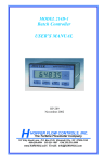
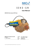
MODEL 302di
Field Mounted Rate/Totalizer
USER’S MANUAL
HP-295
November 2002
107 Kitty Hawk Lane, P.O. Box 2145, Elizabeth City, NC 27906-2145
800-628-4584 252-331-1997 FAX 252-331-2886
www.hofferflow.com E-mail: [email protected]
NOTICE
Hoffer Flow Controls, Inc. makes no warranty of any kind with regard to this
material, including, but not limited to, the implied warranties of
merchantability and fitness for a particular purpose.
This manual has been provided as an aid in installing, connecting,
calibrating, operating, and servicing this unit. Every precaution for
accuracy has been taken in the preparation of this manual; however,
Hoffer Flow Controls, Inc. neither assumes responsibility for any
omissions or errors that may appear nor assumes liability for any
damages that result from the use of the products in accordance with
information contained in the manual.
HOFFER FLOW CONTROLS' policy is to provide a user manual for each item
supplied. Therefore, all applicable user manuals should be examined before
attempting to install or otherwise connect a number of related subsystems.
During installation, care must be taken to select the correct interconnecting wiring
drawing. The choice of an incorrect connection drawing may result in damage to
the system and/or one of the components.
Please review the complete model number of each item to be connected and locate
the appropriate manual(s) and/or drawing(s). Identify all model numbers exactly
before making any connections. A number of options and accessories may be
added to the main instrument, which are not shown on the basic user wiring.
Consult the appropriate option or accessory user manual before connecting it to the
system. In many cases, a system wiring drawing is available and may be requested
from Hoffer Flow Controls.
This document contains proprietary information, which is protected by
copyright. All rights are reserved. No part of this document may be
photocopied, reproduced, or translated to another language without the prior
written consent of Hoffer Flow Controls, Inc.
HOFFER FLOW CONTROLS’ policy is to make running changes, not model
changes, whenever an improvement is possible. This affords our customers the
latest in technology and engineering. The information contained in this
document is subject to change without notice.
THIS WARRANTY IS EXPRESSLY IN LIEU OF ALL OTHER
WARRANTIES, EXPRESSED OR IMPLIED, INCLUDING ANY IMPLIED
WARRANTY OF MERCHANTABILITY OR FITNESS FOR A
PARTICULAR PURPOSE. HFC SHALL NOT BE LIABLE FOR ANY LOSS OR
DAMAGE RESULTING, DIRECTLY OR INDIRECTLY, FROM THE USE OR LOSS OF USE OF
THE GOODS. WITHOUT LIMITING THE GENERALITY OF THE FOREGOING, THIS
EXCLUSION FROM LIABILITY EMBRACES THE PURCHASER'S EXPENSES FOR
DOWNTIME OR FOR MAKING UP DOWNTIME, DAMAGES FOR WHICH THE PURCHASER
MAY BE LIABLE TO OTHER PERSONS, DAMAGES TO PROPERTY, AND INJURY TO OR
DEATH OF ANY PERSONS. HFC NEITHER ASSUMES NOR AUTHORIZES ANY PERSON
TO ASSUME FOR IT ANY OTHER LIABILITY IN CONNECTION WITH THE SALE OR USE
OF HFC'S GOODS, AND THERE ARE NO ORAL AGREEMENTS OR WARRANTIES
COLLATERAL TO OR AFFECTING THE AGREEMENT. PURCHASER'S SOLE AND
EXCLUSIVE REMEDY IS THE REPAIR AND/OR REPLACEMENT OF NONCONFORMING
GOODS AS PROVIDED IN THE PRECEDING PARAGRAPHS. HFC SHALL NOT BE LIABLE
FOR ANY OTHER DAMAGES WHATSOEVER INCLUDING INDIRECT, INCIDENTAL, OR
CONSEQUENTIALDAMAGES.
HFC 9907
Limited Warranty POLICY FOR Hoffer Flow Controls
HOFFER FLOW CONTROLS, INC. ("HFC") warrants HFC's Precision Series and API
Series of turbine flowmeters to be free from defects in material and workmanship under
normal use and service, only if such goods have been properly selected for the service
intended, properly installed and properly operated and maintained as described in the
turbine flowmeter manual. Reference "turbine flowmeter manual" for specific details.
This warranty shall extend for a period of five (5) years from the date of shipment to the
original purchaser and covers the Precision Series and API Series of flowmeters All other
HFC products carry a one (1) year warranty. This warranty is extended only to the
original purchaser ("Purchaser"). Purchaser's sole and exclusive remedy is the repair
and/or replacement of nonconforming goods as provided in the following paragraphs.
In the event Purchaser believes the Hoffer product is defective, the product must be
returned to HFC, transportation prepaid by Purchaser, within the appropriate warranty
period relative to the product. If HFC's inspection determines that the workmanship or
materials are defective and the required maintenance has been performed and, has been
properly installed and operated, the product will be either repaired or replaced, at HFC's
sole determination, free of additional charge, and the goods will be returned,
transportation paid by HFC, using a transportation method selected by HFC.
Prior to returning the product to HFC, Purchaser must obtain a Returned Material
Authorization (RMA) Number from HFC's Customer Service Department within 30 days
after discovery of a purported breach of warranty, but not later than the warranty period;
otherwise, such claims shall be deemed waived. See the Return Requests/inquiries
Section of this manual.
If HFC's inspection reveals the Hoffer product to be free of defects in material and
workmanship or such inspection reveals the goods were improperly used, improperly
installed, and/or improperly selected for service intended, HFC will notify the purchaser
in writing and will deliver the goods back to Purchaser upon receipt of Purchaser's
written instructions and agreement to pay the cost of transportation. If Purchaser does not
respond within thirty (30) days after notice from HFC, the goods will be disposed of in
HFC's discretion.
HFC does not warrant the product to meet the requirements of any safety code of any
state, municipality, or other jurisdiction, and Purchaser assumes all risk and liability
whatsoever resulting from the use thereof, whether used singlely or in combination with
other machines or apparatus.
This warranty shall not apply to any HFC product or parts thereof, which have been
repaired outside HFC's factory or altered in any way, or have been subject to misuse,
negligence, or accident, or have not been operated in accordance with HFC's printed
instructions or have been operated under conditions more severe than, or otherwise
exceeding, those set forth in the specifications.
FOR NON-WARRANTY REPAIRS OR CALIBRATIONS, consult
HOFFER FLOW CONTROLS for current repair/calibration charges.
Have the following information available BEFORE contacting HOFFER
FLOW CONTROLS:
1. P.O. number to cover the COST of the repair/calibration,
2. Model and serial number of the product, and
3. Repair instructions and/or specific problems relative to the product.
HFC 9907
CONTENTS
1.
Introduction---------------------------------------------------------------- 1
1-1
Model Number Designation ------------------------------------------2
1-2
Intrinsic Safety Considerations---------------------------------------4
2.
Specifications -------------------------------------------------------------- 6
2-1
General -------------------------------------------------------------------6
2-2
Battery Powered Version ----------------------------------------------6
2-3
Loop Powered 4-20mA Output Version-----------------------------6
2-4
DC Power/Alarm Version ---------------------------------------------7
2-5
Physical ------------------------------------------------------------------7
3.
Operation------------------------------------------------------------------- 9
3-1
Display -------------------------------------------------------------------9
3-1-1
Front Panel Operation -------------------------------------------9
3-2
Test Mode-------------------------------------------------------------- 10
3-3
Filtering ---------------------------------------------------------------- 10
3-4
Calculation of Rate and Total--------------------------------------- 12
3-5
Total Conversion------------------------------------------------------ 13
3-6
Non-linearity Correction Feature ---------------------------------- 14
4.
Configuring ---------------------------------------------------------------15
4-1
Configuration Steps -------------------------------------------------- 16
4-2
Example ---------------------------------------------------------------- 20
5.
Versions--------------------------------------------------------------------21
5-1
Battery Powered Version -------------------------------------------- 21
5-2
4-20mA Output with Alarms Version----------------------------- 22
5-3
DC POWER VERSION --------------------------------------------- 24
6.
Flowmeter Input ---------------------------------------------------------27
7.
Intrinsic Safety Connections-------------------------------------------31
7-1
Coils--------------------------------------------------------------------- 31
7-2
Simple Apparatus ----------------------------------------------------- 31
7-3
Alarm Outputs--------------------------------------------------------- 33
8.
Installation ----------------------------------------------------------------35
8-1
Wall Mounting -------------------------------------------------------- 35
8-2
Panel Mount Version------------------------------------------------- 36
8-3
Removing The Front Panel------------------------------------------ 37
8-4
The Main Electronics ------------------------------------------------ 39
8-5
Wiring ------------------------------------------------------------------ 40
8-6
Terminal Designations ----------------------------------------------- 40
Model 302di
HP-295
Model 302di
HP-295
Introduction
1
1. INTRODUCTION
The Model 302d Rate-Totalizer is a microprocessor-based instrument
which accepts frequency or pulse inputs from a wide range of
flowmeters. The instrument displays Flowrate, a Resettable Total,
and an Accumulated Total directly in engineering units.
The instrument is compatible with a wide range of flowmeters. Links
on the input board enable the circuit to be configured for millivolt
signals, reed switches, pulse trains, and most other signal types.
Three different versions of the instrument are available:
1.
2.
3.
A Battery Powered version with no outputs
A Loop Powered version with 4-20mA output and
alarms/pulse output.
A DC Powered version with either high and low flow alarms
or low flow alarm and pulse output
The Model 302d is fully configurable with K-factors, decimal point
positions, filter constants, and timebase being programmed via the front
panel switches.
This instrument conforms to the EMC-Directive of the Council of
European Communities 89/336/EEC and the following standards:
Generic Emission Standard EN 50081-1
Residential, Commercial
& Light Industry
Environment.
Generic Emission Standard EN 50081-2
Industrial Environment.
Generic Emission Standard EN 50082-1
Residential, Commercial
& Light Industry
Environment.
Generic Emission Standard EN 50082-2
Industrial Environment.
In order to comply with these standards, the wiring instructions in
Section 8.5 must be followed.
Model 302di
HP-295
2
Introduction
1-1
Model Number Designation
MODEL 302di
DC POWERED RATE/TOTALIZER, INTRINSICALLY SAFE
(TO BE USED ONLY WHEN APPROVALS ARE REQUIRED)
MODEL 302di-( A )- ( B )-( C )
TYPE OF MOUNTING
POWER OPTIONS
OPTIONS
TYPE OF MOUNTING
MODEL 302di-( A )-( )-( )
OPTION ( A )
(1)
PANEL MOUNT
(2)
WALL MOUNT WITH CABLE GLANDS
(3)
EXPLOSION-PROOF WITH 1" BOTTOM MOUNT WITH UNION
(SEE NOTE 5)
(4)
1" NPT BOTTOM MOUNT WITH UNION (SEE NOTE 5)
(5)
1" NPT REAR MOUNT WITH UNION (SEE NOTE 5)
(6)
2" GALVANIZED PIPE BRACKET (SEE NOTE 6)
POWER OPTIONS
MODEL 302di-( )-( B )-( )
OPTION ( B )
(O)
LITHIUM BATTERY (INTRINSICALLY SAFE)
(3L)
(4L)
NOTE:
9-28 VDC POWER WITH LO ALARM, AND HI ALARM OR AN OPEN
COLLECTOR OPTO ISOLATED PULSE OUTPUT (USER
SELECTABLE). MEMORY BACKUP WITH LITHIUM BATTERY.
LOOP POWERED WITH LO ALARM, AND HI ALARM OR AN OPEN
COLLECTOR OPTO ISOLATED PULSE OUTPUT (USER
SELECTABLE). INTRINSICALLY SAFE WITH BARRIER IN SAFE
AREA. MEMORY BACKUP WITH LITHIUM BATTERY.
SPECIFY DC POWER (OPTION 3) WHEN USING A REDI-PULSE
COIL INPUT. BATTERY VERSION IS NOT AVAILABLE FOR USE
WITH THE RED-PULSE COIL. LOOP POWERED (OPTION 4L)
MAY BE SPECIFIED, HOWEVER,REDI-PULSE COIL MUST HAVE
AN ISOLATED DC POWER SUPPLY.
Model 302di
HP-295
Introduction
OPTIONS
MODEL 302di-( )-( )-( C )
OPTION ( C )
(CE)
INTERFERENCE CE COMPLIANCE WITH CSA APPROVAL
(CEN)
CENELEC, NRTL/C AND SAA APPROVAL
(CE/CEN) WHEN BOTH APPROVALS REQUIRED
(2)
10 POINT LINEARIZATION
NOTES:
1.
2.
3.
4.
5.
6.
7.
MUST USE ISM INTRINSICALLY SAFE MAGNETIC COIL FOR
INTRINSICALLY SAFE SYSTEM.
STANDARD COILS ARE SUITABLE FOR SYSTEMS THAT DO NOT
REQUIRE INTRINSICALLY SAFE.
LCD DISPLAY: 7 DIGIT 0.4" (10MM) TOTAL CONTINUOUSLY
DISPLAYED
5 DIGIT 0.33" (85MM) CONTINUOUSLY DISPLAYED
RATE, ACCUMULATED DISPLAYED BY KEY
DEPRESSION
BATTERY LIFE FULL 2 YEARS IF CONTINUOUSLY USED.
1" RISER IS REQUIRED ON TURBINE FOR MOUNTING OPTION (3),
(4) OR (5).
A GALVANIZED METAL BRACKET ENABLES THE UNIT TO BE
ATTACHED TO A 2" VERTICALOR HORIZONTAL PIPE.
10 POINT LINEARIZATION MUST BE CALLED OUT.
APPROVALS
OPTIONAL APPROVALS UNDER (CEN) OPTION
INTRINSICALLY SAFE
WATER TIGHT TO IP67 (NEMA 4X)
The Model 302di
Model 302di
HP-295
3
4
1-2
Introduction
Intrinsic Safety Considerations
The Model 302d is certified for use in hazardous areas and has both
CENELEC and CSA C/NRTL approvals.
The Model 302d certification details are:
CENELEC Approval:
Type of Protection:
Group:
Temperature Class:
Kema 98.E.1873.
Ex ia.
IIB.
T4 at ambient temperature of 60°C.
CSA C/NRTL Approval
File Number:
Type:
LR 104 840-5.
Class 1, Groups C and D
When installing in hazardous areas, the instrument must be installed
according to the guidelines in Section 6 and in accordance with
standards for wiring and installation in hazardous areas.
Flowmeter Inputs
Entity Parameters on the flowmeter input enable connection to a
wide range of approved sensors.
Input Parameters are:
Ui = 24V
Ii = 20mA
Pi = 320mW
The internal capacitance and inductance seen on these terminals is
0.002 µF and 0 mH.
Output Parameters are:
Uo = 10.0V
Io = 9.0mA
Maximum allowed external capacitance is 60 µF.
Maximum allowed external inductance is 1.5H.
Model 302di
HP-295
Introduction
4-20mA/DC Power
The input can be connected to IS circuits with the following
maximum values:
Ui = 28V
Ii = 93mA
Pi = 653mW.
The internal capacitance and inductance seen on these terminals is
0.1 µF and 0 mH.
Relay Outputs
The output can be connected to IS circuits with the following
maximum values:
Ui = 28V
Ii = 93mA
Pi = 653mW.
The internal capacitance and inductance seen on these terminals is
0.1 µF and 0 mH.
Model 302di
HP-295
5
6
Specifications
2. SPECIFICATIONS
2-1
General
Display:
Resettable Total:
Accumulated Total:
Rate:
K-factor:
Decimal Points:
Timebase:
Frequency Range:
Signal Type:
2-2
Battery Powered Version
Type:
Battery Life:
2-3
LCD, continuously powered
7 digits with 10mm (0.4") high digits.
Resettable from front panel.
Displayed when the ACCUM TOTAL button
is pressed.
4½ digits with 8.5mm (0.33") high digits.
The pulses per unit of measure (e.g.
pulses/gallon) is configurable in the range
0.000001 to 999,999.
Decimal Point positions are fully
configurable for both rate and total.
Rate can be displayed in units per second,
minute, hour, or day.
0.01Hz to 10kHz.
Link settable for Sinewave (15mV P-P
minimum), Open Collector, Reed Switch, or
Pulse.
Two lithium battery packs.
5 years typical.
Loop Powered 4-20mA Output Version
Scale:
Resolution & Linearity:
Accuracy:
Update Time:
Connection:
Loop Power Supply:
Supply Backup:
Model 302di
The 4mA and 20mA points are
configurable.
0.05% of span.
0.05% of span @ 25ºC.
0.1% (typ) of span, full temperature range.
0.5 seconds.
Two wire.
9-28 volts.
Lithium battery.
HP-295
Specifications
2-4
DC Power/Alarm Version
Outputs:
Switching Power:
DC Power Input:
Supply Backup:
Pulse Duration:
2-5
7
Two open collector outputs suitable for
driving DC solenoids or external relays. The
outputs provide high and low flow alarms or
low flow alarm and pulse output.
200mA 30VDC maximum.
9-28 Volt at 4mA maximum.
Lithium battery.
1ms if CAL0 = 2 (unscaled pulse output)
If CAL0 = 1 (scaled pulse output)
automatically adjusts to the output frequency:
a. 1ms output > 50Hz
b. 10ms output = 5 … 50Hz
c. 100ms output < 5Hz
Physical
Temperature:
Dimensions:
Protection:
Cable Entry:
Wall Mounting:
Pipe Mounting:
Turbine Meter
Adapter:
Panel Mounting:
Model 302di
Operating:
-20°C to 60°C.
97mm (3.8") high x 150mm (5.9") wide x
41mm (1.6") deep (cable glands not
included).
Sealed to Nema 4X or IP67 standards.
By cable glands.
Universal Mounting Bracket supplied
(Standard).
A galvanized metal bracket is available which
enables the Model 302d to be attached to a 2"
vertical or horizontal pipe.
An optional mounting stem is available for
mounting the Model 302d directly on turbine
flowmeters which have a 1" MNPT boss.
Supplied with mounting brackets. Terminals
accessible from the rear. Not watertight.
Cutout: 141mm (5.6”) wide x 87mm (3.4”)
high.
HP-295
8
Operation
3. OPERATION
The Model 302d Rate Totalizer accepts a frequency or pulse input from
a wide range of flowmeters. The instrument is fully configurable with
all operating parameters and calculation constants configurable from
the front panel. The setup parameters are stored in a non-volatile
memory and are retained for at least 10 years in the event of a power
loss.
3-1
Display
The Model 302d Rate Totalizer will display:
Rate
Resettable Total
Accumulated Total
Both the Rate and Resettable Total are continuously displayed while
the Accumulated Total is only displayed when the ACCUM TOTAL
key is pressed. The Resettable Total can be reset at any time by
pressing the RESET key.
3-1-1
Front Panel Operation
The keys on the front panel have the following functions:
This key displays the Accumulated Total.
This key resets the Resettable Total at any time.
This key is used during the Program Mode.
Model 302di
HP-295
Operation
3-2
9
Test Mode
The instrument has a Test Mode which can be entered by
simultaneously pressing all three front panel keys. The tests are as
follows:
Lo Test
By pressing the
key, the low alarm
output (if installed) will go low. If a 4-20mA option
is installed, the output will go to 4mA.
Hi Test
By pressing the
key, and depending on the
programmed pulse output mode, the high alarm output
(if installed) will:
a.
b.
c.
go low if CAL0 = 0 (high alarm output).
output 100ms pulses every 0.5 sec if CAL0 = 1
(scaled pulse output).
output 1ms pulses every 0.5 sec if CAL0 = 2
(unscaled pulse output).
If a 4-20mA option is installed, the output will go to
20mA.
Display Test
By pressing the
display will flash.
key, all segments of the
To exit the test mode, all three front panel keys are pressed
simultaneously.
3-3
Filtering
Frequency fluctuations caused by pulsating flow through a flowmeter
can interfere with the precision of Rate. For this reason the
Model 302d Rate Totalizer has a digital filter which will average out
these fluctuations and enable accurate readings.
The degree of filtering of the input signal can be adjusted, depending
on the amount of fluctuation and the particular application. Values
from 1 to 99 can be programmed, where 1 corresponds to no filtering
and 99 corresponds to heavy filtering. Such flexibility in filtering
means that highly accurate and stable readings can be obtained, while
minimizing excessive lag.
Model 302di
HP-295
10 Operation
When programming the degree of filtering, it is advisable to start with
no filtering (the factor equals 1) and gradually increase until a steady
reading is obtained. It is important that the filtering is not too heavy
because this will cause an overdamped response.
The diagram below shows a pulsating signal input together with the
effect of filtering.
As a guideline to the degree of filtering to be used, the following table
shows the response to a step change in input. The value, CAL 6, is the
filter constant which is entered during the configuration routine. The
times for the display value to reach 90% and 99% of full swing are
given in seconds, for different values of CAL 6.
A
90%
99%
1.00
2.00
4.00
6.00
10.00
15.00
20.00
25.00
35.00
45.00
60.00
75.00
90.00
99.00
0.00
1.00
2.00
3.00
5.00
8.00
11.00
14.00
20.00
25.00
34.00
43.00
52.00
57.00
0.00
2.00
4.00
6.00
11.00
17.00
22.00
28.00
40.00
51.00
69.00
86.00
103.00
113.00
Table 1 - Response to a step Input (in seconds).
Note that if CAL 6 is set to 01 there is no filtering of the input signal.
Model 302di
HP-295
Operation
3-4
11
Calculation of Rate and Total
The flowrate, R, is calculated as follows:
R=
fxH
S
where f is the input frequency in Hz.
H is the timebase of rate and is 1 for seconds, 60 for
minutes, 3600 for hours, and 86,400 for days.
S is the Scaling Factor.
The Scaling Factor, S, is equal to the K-factor of the flowmeter
expressed in pulses per unit volume.
The user configures the Scaling Factor and selects the timebase during
the Configuration procedure.
Model 302di
HP-295
12 Operation
3-5
Total Conversion
The Total Conversion Factor enables the RATE to be displayed in one
engineering unit (e.g. gallons/minute) and the TOTALS to be displayed
in another engineering unit (e.g. barrels).
The Total Conversion Factor is a division factor which can be used to
convert the totals to the different unit. The Total Conversion factor
affects the resettable and accumulated totals.
For Example:
If the Rate is required in gallons per minute:
1. The Scaling Factor would be configured as pulses per gallon
2. The timebase would be configured as minutes
If the Totals are required in barrels:
3. The Total Conversion factor is configured as 42 (there are 42
gallons in a barrel). All totals will now totalize in barrels.
Some common units are given below together with the Total
Conversion constant which should be configured.
Rate*
Gallons (US)/
Litres/
ml/
Mgallons/
Totals
Barrels (oil)
Kilolitres
Litres
Acre-feet
TOTCON
42.000
1000
1000
0.32587
* Units per second, minute, hour, or day. The timebase is configured
separately during Configuration.
Model 302di
HP-295
Operation
3-6
13
Non-linearity Correction Feature
This optional feature allows the instrument to be used with non-linear
flowmeters providing up to 10 non-linearity corrections points.
The following diagram graphs the change in scaling factor with
frequency for a hypothetical flowmeter. The heavy line represents the
actual scaling factor of the flowmeter, while the light line is the
approximation used in the instrument.
Up to 10 frequencies and scaling factors may be configured.
Frequencies must be entered in ascending order. Linear Interpolation is
used between points. If the input frequency is below the first or above
the last frequency, the scaling factor will maintain a constant value.
Note: Display update time increases to 1 second if the non-linearity
correction feature is used with the battery powered version of this
instrument.
Model 302di
HP-295
14 Configuring
4. CONFIGURING
The Model 302d is fully configurable, with all parameters being stored
in non-volatile memory.
The Program Mode can be entered in one of two ways:
1.
2.
The
By removing the lower cover strip (i.e., the dark gray strip
along the bottom of the enclosure), flipping it end-for-end
and replacing it on the enclosure. This brings a small
magnet on the inside of the cover strip in contact with a reed
switch inside the instrument. The PROGRAM key is then
pressed to enter the Configuration Mode.
By removing the front section of the enclosure which
contains the main processor board and batteries. Once
removed, the PROGRAM key is pressed to enter the
Configuration Mode.
key is used to step through the program (CAL
sequences) and the
and
keys on the front panel
are used to change and increment the flashing digits. Note that only
flashing digits may be changed.
Up to nineteen CAL steps are accessible, depending on which options
are installed. The CAL number is displayed on the lower display and
the parameter is displayed on the upper display.
Model 302di
HP-295
Configuring
4-1
15
Configuration Steps
Step
Comment
CAL 0
Pulse Output (applies to DC Power/Alarm version only)
0 = No pulse output, low and high alarms
1 = Scaled pulse output and low alarm
2 = Unscaled pulse output and low alarm
CAL 1
CAL 2
Scaling Factor - whole number
Scaling Factor - numbers after the decimal point
The Scaling Factor is the pulses per unit of
measure (e.g. pulses/litre, pulses/gallon, etc).
The Scaling Factor can be programmed in the
range of 0.000001 - 999,999.
CAL 3
Cutoff Frequency
This determines the Cutoff Frequency in the
range of 0.01 - 0.99Hz. the default setting is
0.25 Hz.
NOTE: Care must be taken when setting this
value as a low value may cause a
slow update time.
CAL 4
Decimal Point for Rate Display
The flowrate can be displayed with 0, 1, 2, or 3
decimal places (e.g., 2.000).
CAL 5
Timebase for Rate
The Rate can be displayed in units per second,
minute, hour, or day.
0 = second
1 = minute
2 = hour
3 = day.
Model 302di
HP-295
16 Configuring
Step
Comment
CAL 6
Filter
The filter constant for filtering the input signal.
1 No filtering
to
99 Very heavy filtering.
CAL 7
Decimal Point for Total Display
The totals can be displayed with 0, 1, 2, or 3
decimal places (e.g., 2.000).
CAL 8
CAL 9
Total Conversion Factor - whole number
Total Conversion Factor - numbers after the decimal
point
The Total Conversion Factor enables the Rate
to be displayed in one engineering unit and the
Totals to be displayed in another engineering
unit. The Total Conversion Factor can be
programmed in the range of 0.000001 999,999.
Set to 1.000 if totals and rate are in the same
unit e.g. litres.
NOTE:
CAL 10
CAL 11
Model 302di
CAL 10 thru CAL 13 are displayed regardless of
whether the high and low alarms are installed. If
the high and low alarms are not installed, these
parameters can be ignored.
Low Alarm - whole number
Low Alarm - numbers after the decimal point
CAL 10 & 11 program the flowrate below
which the low alarm relay will close. The
value can be programmed in the range 0 to
999,999.
HP-295
Configuring
17
Step
Comment
CAL 12
CAL 13
High Alarm/Pulse Output Factor - whole number
High Alarm/Pulse Output Factor - numbers after the
decimal point
CAL 12 & 13 program the flowrate above
which the high alarm relay will close. The
value can be programmed in the range 0 to
999,999.
If the scaled pulse output is selected (CAL0 =
2) then the value represents the total per pulse
(e.g., 5 gallons per pulse).
NOTE:
CAL 14 thru CAL 17 are displayed regardless of
whether the 4-20mA re-transmission is installed.
If the 4-20mA re-transmission is not installed,
these parameters can be ignored.
CAL 14
CAL 15
4mA Re-transmission - whole number
4mA Re-transmission - numbers after the decimal point
CAL 14 & CAL 15 represent the flowrate at
which 4mA will be output.
CAL 16
CAL 17
20mA Re-transmission - whole number
20mA Re-transmission - numbers after the decimal point
CAL 16 & 17 represent the flowrate at which
20mA will be output.
NOTE:
CAL 18
CAL 18 and INP##/OUT## fields are displayed
only when the optional Non-Linearity Correction
Feature is installed.
Number of non-linearity correction points.
00 = Non-linearity correction disabled
xx = Non-linearity correction enabled; ‘xx’
points to enter. Maximum 10 points.
Model 302di
HP-295
18 Configuring
Step
NOTE:
INP ##
INP ##
Comment
The number of INP & OUT fields displayed will
equal the number of correction points entered in
CAL 18.
Input Freq Point ## - whole number
Input Freq Point ## - numbers after the decimal point
Input points must be entered in ascending
order.
OUT ##
OUT ##
Output Scaling Factor Point ## - whole number
Output Scaling Factor Point ## - numbers after the
decimal point
Output points must NOT be set to zero.
SOFT
Model 302di
Software Version
HP-295
Configuring
4-2
19
Example
A flowmeter produces 20.538 pulses per gallon and has a maximum
output frequency of 200Hz. It is required to display the flowrate in
gallon/min with 1 digit to the left of the decimal point and the total in
gallon with no digits to the left of the decimal. A 4-20mA output is
installed and 4mA is to represent 0 gallon/m and 20mA is to represent
500 gallon/m. The instrument is then programmed as follows:
The Calibration Mode is entered by removing the lower cover strip
(i.e., the dark gray strip along the bottom of the enclosure) and flip it
end-for-end and replacing it back on the enclosure. The following
values are then entered:
Step
Value
CAL00
0
CAL01
00020
Scaling Factor (Whole Numbers)
CAL02
5380
Scaling Factor (Decimals)
CAL03
0.25
Cutoff Frequency
CAL04
1
Rate decimal position
CAL05
1
Timebase
CAL06
01
Filter disabled
CAL07
0
Total decimal position
CAL08
0001
Total Conversion (set to 1.0000)
CAL09
0000
Total Conversion (decimals)
CAL10
00000
Low Alarm (not installed)
CAL11
0000
Low Alarm (not installed)
CAL12
00000
High Alarm (not installed)
CAL13
0000
High Alarm (not installed)
CAL14
00000
4mA Output (Whole Numbers)
CAL15
0000
4mA Output (Decimals)
CAL16
00500
20mA Output (Whole Numbers)
CAL17
0000
20mA Output (Decimals)
SOFT
1.01
Software Version
CARD
0
Model 302di
Description
No Pulse Output
Battery Version input card
HP-295
20 Versions
5. VERSIONS
5-1
Battery Powered Version
The battery powered version of the Model 302d is designed for
operation in the field without external power sources. Lithium batteries
provide sufficient power to operate the instrument for up to 5 years and
the operator is warned of a low power condition by a message on the
LCD display.
New batteries can be purchased from Hoffer Flow Controls, Inc. and
can be replaced in the field without compromising the IS approvals.
There are two battery packs in each instrument and care must be taken
to replace only one pack at a time so that there is always power
connected to the memory. Failure to do this may result in the loss of
setup parameters and totals.
Model 302di
HP-295
Versions
5-2
21
4-20mA Output with Alarms Version
this version combines the features of the DC powered with a 4-20mA
output.
The 4-20mA output provides a two wire re-transmission of the
flowrate. Both the 4mA and 20mA points are fully configurable so that
the output can span across the entire operating range or, alternatively,
across a small section of the operating range.
The instrument draws its operating power from the 4-20mA loop and
lithium batteries for backup if the 4-20mA loop is interrupted. The
alarm/pulse outputs are NOT supported if the 4-20mA loop is
interrupted.
Specification
Resolution & Linearity:
Accuracy:
Response (4mA to 20mA):
Loop Power Supply:
0.05% of span.
0.05% of span at 25ºC.
0.1% (typ) of span full
temperature range.
0.5 Seconds.
9-28 VDC.
Important
Since the 4-20mA output is designed to provide power to the
Model 302d, it is not isolated from the input. Hence, all sensors must
be self-powering (such as MAG coils & reed switches). If external
power is required to power the sensor (e.g. Redi-Pulse pick-ups, Hall
Effect sensors, or opto-sensors), the power supply delivering the
external power must be isolated from the 4-20mA loop supply.
Model 302di
HP-295
22 Versions
Typical Connection
Connection to a Sensor requiring External Power
Model 302di
HP-295
Versions
5-3
23
DC Power Version
The DC Power version operates from an external power source
between 9-28VDC and draws no more than 4mA. This enables the
instrument to be powered from AC adapters and eliminates the need to
run AC voltages in the field.
The instrument uses lithium batteries for backup if the DC power is
interrupted. However, alarms and/or pulse outputs are NOT supported
if the DC power is interrupted.
Open collector outputs are also provided for high and low flowrate
alarms. If a pulse output is programmed, terminals 5 & 6 act as a pulse
out. The outputs can sink up to 200mA and can be used to control
external relays, lights, or audible alarms. The outputs are internally
protected against voltage spikes which can be caused by relays and
coils.
Both outputs are separately isolated via opto isolators.
The switching points can be programmed during the setup mode and
the low flow alarm will switch on whenever the flowrate drops below
the programmed flowrate. Similarly, the high alarm switches on
whenever the flow exceeds the high setpoint.
If a Scaled Pulse Output is programmed, a pulse will be output every
preset value of total. For example, if the total is in gallons, then
programming 5 will output one pulse every 5 gallons. If an Unscaled
Pulse Output is programmed, output pulses will follow the input
frequency from the flowmeter.
Specification for Alarm Outputs
Maximum Current (sink): 200mA
Maximum Voltage:
30VDC.
Saturation Voltage:
0.8VDC across outputs when in the
“ON” state.
Isolation:
Both outputs are separately isolated.
Pulse Frequency:
500Hz maximum.
Pulse Duration:
1ms if CAL0 = 2 (unscaled pulse
output)
If CAL0 = 1 (scaled pulse output) the
duration automatically adjusts to the
output frequency:
a. 1ms for output > 50Hz
b. 10ms for output = 5…50Hz
c. 100ms for output < 5Hz
Model 302di
HP-295
24 Versions
Connections
Model 302di
HP-295
Flowmeter Input
25
6. FLOWMETER INPUT
The Model 302d has an input conditioning circuit which will accept
signals from most pulse or frequency producing flowmeters. Links on
the rear panel enables the input circuit to be configured for the different
signal types.
The input will interface directly to:
−
−
−
−
−
Turbine Flowmeters
Open Collector Outputs
Reed Switches
Logic Signals
Two Wire Proximity Switches.
The following pages give examples of interconnection to various signal
outputs and a circuit diagram of the input is also provided.
For pulse or logic type signals, the input switching threshold is 1.3
volts. Hence, the input signal must have a "LOW" voltage of less than
1.2 volts and a "HIGH" voltage of greater than 1.4 volts.
For flowmeters with coils, the minimum input voltage is 15mV P-P.
All inputs are protected for over voltage up to 28 volts.
Model 302di
HP-295
26 Flowmeter Input
Simplified Frequency Input Circuit
Model 302di
HP-295
Flowmeter Input
1.
2.
3.
27
MAG Coil
Redi-Pulse Pick-up (Pulse output)
Redi-Pulse Pick-up (Open Collector)
Model 302di
HP-295
28 Flowmeter Input
4.
Squarewave, CMOS or Pulse
5.
Open Collector
6
Reed Switch - Battery Powered
Model 302di
HP-295
Intrinsic Safety Connections
7. INTRINSIC SAFETY
CONNECTIONS
When installing the Model 302d in hazardous areas, the wiring and
installation must comply with appropriate installation standards.
The approval uses entity parameters on the input for connections to the
flowmeter and an associated apparatus type approval for the 4-20mA
output. The 4-20mA output must, therefore, only be connected as
shown on the following page to barriers with the specified parameters.
7-1
Coils
The Model 302d will connect directly to a turbine flowmeter with a
certified IS coil or other certified IS sensor which produce a pulse
output, provided they do not exceed the following input parameters:
Ui = 24V
Ii = 20mA
Pi = 320mW
The maximum allowed capacitance and inductance of the pulser or coil,
including cabling is :
Cext = 60µF
Lext = 1.5H
The internal capacitance and inductance of the Model 302d seen on the
input are negligibly small with Ci = 0.02uF and Li = 0mH. The
maximum voltage and current produced on the inputs (terminals 8 & 7)
are:
7-2
Uo = 10.0 volts
(open circuit)
Io = 9.0mA
(short circuit)
Simple Apparatus
Devices such as reed switches, which can be classed as “Simple
Apparatus” as defined in the CENELEC standard EN50020, can be
connected to the Model 302d without certification.
Model 302di
HP-295
29
30 Intrinsic Safety Connections
Model 302di
HP-295
Intrinsic Safety Connections
7-3
Alarm Outputs
The low alarm and high alarm/pulse output can be connected to
suitably certified devices providing the circuit is protected with a
barrier with the maximum safety parameters:
Uo = 28V
Io = 93mA
Pmax = 653mW
The maximum allowed capacitance and inductance of the pulser or coil,
including cabling is :
Cext = 60µF
Lext = 1.5H
The input capacitance on these terminals is 0.1uF max and the
inductance is negligible.
Note that the two alarm outputs must be kept as independent IS circuits
and each protected with their own barrier. It is not permissible to
connect these circuits via a common barrier.
Model 302di
HP-295
31
32 Intrinsic Safety Connections
Model 302di
HP-295
Installation
8. INSTALLATION
8-1
Wall Mounting
A wall mounting bracket is supplied with each instrument. The bracket
should be attached to the wall using round head screws (do not use
counter sunk screws). The bracket is mounted with the "tray" section at
the bottom. The instrument is then attached to the bracket at the
bottom with two screws (see diagram below)
Model 302di
HP-295
33
34 Installation
8-2
Panel Mount Version
The panel mount version of the Model 302d is supplied with two panel
mounting brackets and plug-in terminals which are accessible from the
rear of the instrument.
A diagram of the rear panel is shown below:
Model 302di
HP-295
Installation
8-3
Removing The Front Panel
The front of the instrument is removed as follows:
1.
Remove both the top and bottom cover strips (i.e. the dark
plastic strips on the front) by levering a screwdriver under
one end.
2.
Undo the seven screws retaining the front. Note that the
screws should not be removed from the front panel as they
are retained by O-rings.
3.
Pull the front panel free from the housing.
Replacing the front panel of the instrument is the reverse procedure.
However, ensure that the front panel is aligned at both connector points
before tightening the screws.
Model 302di
HP-295
35
36 Installation
Model 302di
HP-295
Installation
8-4
The Main Electronics
The front section of the housing contains the microprocessor, batteries
and display.
When replacing the lithium battery packs, only one battery pack should
be replaced at a time so that there is always one pack connected to
power the memory.
It is also possible to adjust the display contrast via a small
potentiometer on the board. The DISPLAY CONTRAST control is
shown below and this can be adjusted for optimum contrast.
Adjacent to this control is a RESET switch which can be used to reset
the microprocessor. Note that pressing this button will reset all Setup
Parameters and set all totals to zero.
The Main Electronics
Model 302di
HP-295
37
38 Installation
8-5
Wiring
When connecting the Model 302d, it is good practice to use shielded
cable. The shield should be connected to earth ground near the
instrument. The other end of the shield should not be connected.
In order to comply with the requirements for Electromagnetic
Compatibility, as per EMC-Directive 89/336/EEC of the Council of
European Community, this wiring practice is mandatory.
8-6
Terminal Designations
All Versions
7
8
Pulse Input (-)/Coil Input
Pulse Input (+)/Coil Input
3
4
Low Alarm (-)
Low Alarm (+)
5
6
High Alarm/Pulse Output (-)
High Alarm/Pulse Output (+)
4-20mA Output
1
2
4-20mA (-)
4-20mA (+)
DC Power Versions
1
2
DC Power
DC Power
Model 302di
0V
+9 to 28 VDC
HP-295