1
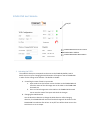
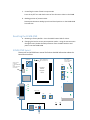
EVMB-‐ICNR Quick experience guide Dear Customer, Thanks for choosing ConnectOne for your IoT experience. The EVMB-‐ICNR is an iChipNet Ready evaluation kit which will allow you to experience Connect One’s iChipNet, a complete IoT end to end solution. The WiFi module on the EVMB-‐ICNR has been programmed with special host website specifically designed to allow you to control three Programmable Input Output Controls (PIOCs) and one Analog input that located on the EVMB-‐ICNR board. Using the internal host website you will be able to control the direction of the PIOC (input or Output), force changes on the EVMB-‐ICNR board while in output state, and receive status of the PIOC while in input state. The purpose of this quick guide is to allow you to access the EVMB-‐ICNR internal host website using Connect One’s Device Connectivity Server (DCS) which is a device management application for remote access to devices in the field. It is recommended that you be familiar with the basic EVMB User Manual located in Connect One’s web site under the “Products” tab (http://www.connectone.com/?page_id=3764). The kit includes the following: EVMB EVM-‐iW-‐SMG2SMT-‐OB Evaluation Master Kit Evaluation WiFi Daughter Board for iW-‐SMG2SMT-‐OB with special host website Setup and usage instructions Please carefully follow the below instructions for the best iChipNet experience: 1. Device Connectivity Server (DCS) account setup The DCS is the cloud server to which devices are registered. It allows remote access to a device for the purpose of control, status and configuration. A. Browse to www.ichipnet.com/managernew B. Click “Create Account” and follow the instruction until complete C. Wait for an activation email, click on the link to access your new DCS account using the account name and password 2. iChipNet Ready Evaluation Board setup Using the supplied power supply, hook up the EVMB-‐ICNR to the power and turn it on. The EVMM-‐ICNR is set up as a WiFi Access Point by default. A. On your computers’ WiFi network connection list, search for the ICNR S/N Access Point. The S/N is an 8 digit number starts with 140. The S/N label is located on the module. B. Once connected to the EVMB-‐ICNR s/n access point, browse to: 10.0.0.1 3. Setting up the EVMB-‐ICNR for internet connection Using your local access point connection credential, the EVMB-‐ICNR will connect to the internet and register itself to the Device Connectivity Server (DCS). A. In the WiFi Configuration section please enter the SSID of your local router, the Security type and the Password Phrase B. In the Device Connectivity Server section, please enter the account name you created in section 1 above and give your EVMB-‐ICNR a name. C. Click submit. At this stage, the unit will reset itself into client mode and will use your local access point for Internet connectivity. The RF Led on the module will blink while searching for your local access point and will stay ‘on’ when the access point detected and associated. Upon connecting, the EVMB-‐ICNR will automatically register itself in the Device Connectivity Server (DCS) under the account name you have created in section 1 and will use the name you have set in section 3-‐B. Rdyns LED on the EVMB-‐ICNR will be ‘on’ to indicate the module is connected to the DCS. Remote device access Using the Device Connectivity Server for remote device access A. Browse to www.ichipnet.com/managernew B. Enter your account name and password and click “Log In” The Device Connectivity Server will access your account and will show the registered device. Clicking the icon under “Host Site” will access the EVMB-‐ICNR internal web site. You are now connected to your EVMB-‐ICNR remotely through the internet and are able to access it from any place that has an internet connection. EVMB-‐ICNR Host Website On/off EVMB-‐ICNR Module Serial number EVMB-‐ICNR IP Address EVMB-‐ICNR Module MAC address 1. Activating the PIOC’s The module’s GPIO pins corresponds to the ones on the EVMB. By default, PIOC3-‐ PIOC5 are set to input. Changing the PIOC direction will require a reset to EVMB-‐ICNR in order for the change to be effective. The default is Disable A. Controlling the state of PIOC in input mode a. Input mode: Press the button next to the PIOC on the EVMB-‐ICNR and check the status of the LED image next to the PIOC on the EVMB-‐ICNR host web site. b. Press on the led image next to the PIOC on the EVMB-‐ICNR host web site to reset the state of the input and check the changes B. Changing the PIOC direction Use the direction selectors to change the PIOC direction. After changing direction, the EVMB-‐ICNR will reset itself and the change will be shown on the EVMB-‐ICNR host website after 20 sec. An on/off icon will be shown next to the PIOC that is set as an output. C. Controlling the state of PIOC in output mode Press the on/off icon and check status of the LED next to PIOC on the EVMB D. Reading position of potentiometer Rotate potentiometer Analog input P1 and check position on the EVMB-‐ICNR host web site. Resetting the EVMB-‐ICNR A. Resetting to factory default – Press the MSEL button SW2 for 30 sec B. Changing the back to access point operation mode – Using the remote access through the DCS, delete the SSID parameter form the HOST web site and power reset the EVMB-‐ICNR EVMB-‐ICNR layout Please refer to the EVMB user manual for further detailed information about the board functionalities. Analog Input SPI J2 On – Connected to DCS – on Line Off – Not connected to DCS -‐ Offline Flash – Search for AP ON-‐ Connected to AP SW3 D10 P1 PIOC4 SW4 D3 D6 D9 PIOC3 J7 J10 Rdyns D8 PIOC5 SW5 D5 Evaluated Module Daughter Board USB DEVICE Jumper must be connected To allow EVMB-‐ICNR to be Initially powered as Access Point RF_LED D.Rdy D7 LAN RS232 Host TXD0 D4 RXD0 Rdyns D. Rdy JP1 DTR on RS232 SW1 SW2 VBUS D14 RESET MSEL J9 USB Host J5 J8 Power D13 VDD GND