1
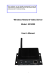
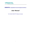
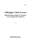
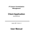
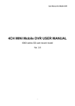
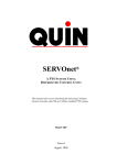
Network Video Server User Manual ST8300 Series Network Video Server User Manual Release date: Revision: Page 1 of 17 2009/04/15 1.0 Network Video Server User Manual Package Content Name Quantity 1pcs 1pcs 1pcs 2pcs 1pcs Video server 12V adapter Software & manual CD Bracket I/O terminal connectors Warning Before Installing Keep the device away from the warter. Keep the device away from the direct sunlight. Keep the device away from the heart sources. Don’t put the device in high temperature and high humid environments. Don’t put the device in unsteady place. Don’t drop the device. Don’t put anything on the device. Don’t disassemble the device except put harddisk in. If you need to put harddisk in, do fix the harddisk with filature. Page 2 of 17 Network Video Server User Manual Content 1 2 3 4 Product Specification ..................................................................................................................................... 4 1.1 Product Summary........................................................................................................................................ 4 1.2 Key Features ............................................................................................................................................... 4 1.3 Datasheet ..................................................................................................................................................... 5 Physical Description ......................................................................................................................................... 6 How to use......................................................................................................................................................... 8 3.1 System ......................................................................................................................................................... 8 3.2 Fix harddisk.............................................................................................................................................. 8 IE clients............................................................................................................................................................ 9 4.1 Before you use IE clients ............................................................................................................................ 9 4.2 Login ...................................................................................................................................................... 10 4.3 Parameters setting ..................................................................................................................................... 11 4.3.1 Real-time video .............................................................................................................................. 11 4.3.2 Replay ............................................................................................................................................ 13 4.3.3 Settings ........................................................................................................................................... 13 4.3.3.1 Basic parameters ...................................................................................................................... 14 4.3.3.2 Network parameters .................................................................................................................... 14 4.3.3.3 Channels parameters ................................................................................................................... 14 4.3.3.4 Alarm parameters ........................................................................................................................ 15 4.3.3.5 Server storage settings ................................................................................................................ 16 Page 3 of 17 Network Video Server User Manual 1 Product Specification 1.1 Product Summary Thanks for choosing us. This series network video server developed with Hi3511 DSP in H.264 arithmetic, which perform higher definition and fluency. The highest resolution can be 720P(1280*720). And it is ok to have 2 SATA interface to connect harddisk for local recording. No PC is required since the built-in Web server has its own IP address. And it is easy to manage, config and monitor through Internet Explore. 1.2 Key Features Video Compression: H.264 Audio Compression: G.722 High definition: 720P:1280×720, D1: 704×576,CIF: 352×288, SVGA、XGA Support PAL/NTSC Bit rate: 32Kbps~8Mbps variable Delay time: less than 200 MSEL(0.20 second) in Lan system Built-in Web server, support IE browse、config、update DDNS, LAN, WAN Bidirectional talkback Dual stream Alarm 5 seconds previous recording, support alarm upload Support image snapshot, video recording Support two SATA harddisk interface, USB interface, SD card interface Page 4 of 17 Network Video Server User Manual 1.3 Datasheet Video Arithmetic Frame Rate Audio Compression Resolution Delay Time Image Adjustment Trigger Event and Action Interface Storage Interface Built-in Web Server DDNS Protocol support Network interface Video Input Interface Video Output Audio Input Audio Output Alarm input/output Security Max. User System System Requirements Operating Temperature Operating Humidity Product Dimension H.264 1/2/4/8ch coding separately PAL:1-25fps NTSC: 1-30fps G.711 or G.722 720P:1280×720, D1: 704×576,Half D1: 704×288,CIF: 352× 288, VGA@60HZ,VGA@75HZ,XGA@60HZ,XGA@75HZ Less than 200 MSEL(0.20 second) in Lan system Adjustment for Brightness, Contrast, Chroma, Saturation, and Image Quality Level Trigger Conditions: Time/Alarm Input/Video Moving Detecting Video Lost Action: Electrical Relay Output Control Peripheral Equipment RS485, RS232 USB, SD Card, 2 SATA interface(Optional) Support IE browse、config、update Built-in DDNS client TCP/IP、HTTP、UDP、RTP/RTCP、RTSP、DHCP、PPPOE、 UPNP、SMTP、FTP、SIP、DDNS、DNS RJ45 10M/100M Mbps High Definition:1 channel, 1 YpbPr input;1 VGA input D1:1,2,4 channel 1.0Vp-p/75Ω /BNC interface CIF:1,2,4,8 channel 1.0Vp-p/75Ω /BNC interface 1 channel analog video 1.0Vp-p/75Ω /BNCinterface 1,2 channel MIC input,1,2,4,8 channel line-in inpput 1,2 channel earphone output,1,2,4,8 channel line-in output 4 channel alarm in, 4 channel alarm out 3 level user and password 10 real-time user Built-in Linux CPU:PⅢ+ Memory:96M+ STD:17 inch @1024×768 -10℃ ~ +55 ℃ ≤85%RH 275(L)mm*46.5(H)mm*157(W)mm(1/2/4ch) 485(L)mm *46.5(H)mm *261.5(W)mm(8ch,1U rack) 378(L)mm *46.5(H)mm *210(W)mm(8ch standard) Page 5 of 17 Network Video Server User Manual 2 Physical Description 1 channel high definition video encoder 2 channel D1/CIF video encoder 4 channel D1/CIF video encoder 8 channel CIF video encoder Page 6 of 17 Network Video Server User Manual 1 channel high definition video encoder back interface 1. Mic in:microphone audio in interface 2. AOUT: earphone audio out interface 3. SW:It is for factory update use. User please don’t use this. 4. LAN:RJ45 network interface(Yellow LED flickering show network connection, green LED constant on show network data transfer state) 5. DC12V:Power in interface 6. VGA:high definition VGA video input interface 7. YpbPr video input interface 8. Audio:BNC audio input interface 9. Vout: analog video out interface 10. SD CARD:SD Card slot 11. Alarmin/Alarm out: Alarm Out 1 1 2 2 3 3 Alarm In 4 4 Alarm out Alarm out Alarm out Alarm out 4 1 2 1 2 3 Alarm in 4 G GND 3 RS232:RS232 interface is to connect to PC to modify the IP of the server. RS485: + - G RS485 + RS485- GND Page 7 of 17 Network Video Server User Manual Front interface of encoder withharddisk 【STATE】: Red LED flicker when the server finish self-checking after power on. 【TX/RX】: Green LED flicker when Ethernet connected. 【LINK】: Yellow LED constant on when Ethernet connected. 【HDD1】: Red LED constant on when harddisk 1 connected. Red LED flicker when there are data transferring. 【HDD2】: Red LED constant on when harddisk 2 connected. Red LED flicker when there are data transferring. 【USB】:USB interface 【RST】:Reset button Return to the factory default parameters guide: 1. Power off 2. Press the reset button without loosen 3. Power on 4. The STATE LED constant on 5. The reply click, loosen the reset button. Now reset succeed. The STATE LED flicker. 3 How to use 3.1 System Operating system: Windows2000server/professional/XP Network protocol: TCP/IP Client PC:P4/128MRAM/40GHD/video card support zoom/DirectX8.0+ 3.2 Fix harddisk 1.If your device need to use harddisk, fix harddisk at first. i、Open the casing with screwdriver. Page 8 of 17 Network Video Server User Manual ii、Fix the harddisk with the bracket in the pachage. Connect the data line to the serial port of the encoder PCB. Refer the photo below which is with two harddisk fixed. 2. Connect the video server to the network, or connect to PC directly. 3. Connect the power on Normally the LAN network connection state yellow LED will flicker in 5 seconds. The harddisk connection ok. 4 IE clients 4.1 Before you use IE clients 1) The default parameters refer Attachment 1. The default IP of video server is 192.168.1.19. And default Subnet Mask is 255.255.255.0. If you need to change the IP address, you need to change the IP address of the PC to be the same network segment and subnet mask the same at first. Change the IP address of the server guide: IE---settings---network parameters---IP address & port. 2) Test the video server start up well or not. Under the Windows System, operate as <Start →run →command> to open the command line dialog box. Ping “192.168.1.19”, as follows: Page 9 of 17 Network Video Server User Manual If it says “Request time out”,the server is not start up normally. Otherwise, the servers tarts up well. 3) When first time visit vider server by Internet Explore,set the safety level to be low to make sure the ActiveX been installed successfully. Guide: Internet Explore---Tools---Internet Option---Safety---custom level---set low level and establish. 4.2 Login 1)Input the IP address in IE. Default IP is http://192.168.1.19 will be out. Default User Name 888888 Default Password 888888 Page 10 of 17 Dialog box as below Network Video Server User Manual 2) When click OK after input the user name and password, user will go into the real-time video page as below. 4.3 Parameters setting 4.3.1 Real-time video Refer photo above. Choose based on you requirement. Click play, all channel will play real-time video. Click stop, all channel real-time video will disconnected. Hook or cancel the channel, to connect or stop this channel’s real-time video. PTZ control: With the buttons below, can control the Iris, zoom, focus, preset point, PTZ control and PTZ speed control. Page 11 of 17 Network Video Server User Manual Click audio, can start and atop the audio. When audio is on, the audio button will be in orange. Click Talkback,can start and stop the bidirectional talkback. When talkback is on, the talkack button will be in orange. Attention that audio should also keep on when talkback on. Click Snapshot, can capture the image currently in *.Bmp format. The image is filed on C:\temp and the file named with device name +time. For example, “c:\temp\Video Server_13_6_37.bmp” Click Record,this button will become orange and start recording. The recording file will be on disk D automatically in *.Mp4 format. The file is named with IP address+channel number+time. For example, “d:\20090205\192.168.1.187_1_130640.mp4” When disk D is full, it will automatically record to the next disk. When all disk is full, it will cover the earliest recording automatically. Click record again, it change to be white and stop recording. 【Video window size】:Click 、 、 , can zoom in zoom out, full screen the video window. The selected size button will become white background. When full screen, click right of the mouse to come back. 【Delay】:Click 、 、 、 、 、 to change the delay level. When the number is bigger, the delay will be longer but more fluent. The selected level number will become white background. Page 12 of 17 Network Video Server User Manual 4.3.2 Replay Local PC storage: Replay the recording file in PC disk. Server storage: Replay the recording file in built-in disk in video server. Input the query date and time and click search, the recording will be in file list. Choose the file and click play, the recording will replay. Note that if you want to search the 24 hour’s file, you need to input such as from 0:0 to 23:59, other than from 0:00 to 0:00. 4.3.3 Settings Page 13 of 17 Network Video Server User Manual 4.3.3.1 Basic parameters Click every item, it will outspread the parameter setting details. Set with the guide is ok. 4.3.3.2 Network parameters Click every item, it will outspread the parameter setting details. Set with the guide is ok. 4.3.3.3 Channels parameters Click every item, it will outspread the parameter setting details. Set with the guide is ok. Area Shield: Click Area shield, dialog box as below will be outspreaded. Page 14 of 17 Network Video Server User Manual The area shield place will be black. This function can be used to protect some area in the video. Such as when be used on ATM, the password input area can set area shield. Hook the Area shield on-off first. Press the left of mouse and choose the area to be shielded. Maximum can choose a quarter of full video area one time. Maximum can set 4 area. Click ok to save. Click clear, this area shield will be cleared. 4.3.3.4 Alarm parameters Click every item, it will outspread the parameter setting details. Set with the guide is ok. Page 15 of 17 Network Video Server User Manual 4.3.3.5 Server storage settings Click every item, it will outspread the parameter setting details. Set with the guide is ok. Page 16 of 17 Network Video Server User Manual Attachment 1 Factory default parameters Default Factory Parameter Setting Parameter Default IP Address 192.168.1.19 Subnet Mask 255.255.255.0 Gateway 192.168.1.1 Multicast Address 235.1.1.1 Multicast Port 6500 DDNS OFF Motion Detection OFF Sensor Alarm OFF PPPOE OFF Remote Host Port 3004 Alarm Host Port 9000 DNS Server Port 8080 Transfer Starting Port 3000 Data Control Port 3001 Remote Transfer Port 3002 Web Port 80 Default User Name & Password Parameter User Name Imagineworld Software Admin Internet Explorer View 888888 Administrator User 888888 High Operator 1 Operator 2 Password (Null) 888888 888888 1 2 The central management software user manual refer Imagineworldclients user manual. Page 17 of 17