Transcript
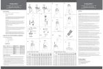
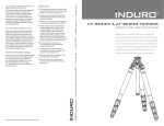
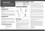
TM
TM
CarbonFlex 8x and AlloyFlex 6m
CarbonFlex 8x and AlloyFlex 6m
Thank you for making Induro your choice for professional photographic gear.
Before using this equipment please read these instructions for proper use and
the best performance.
Thank you for making Induro your choice for professional photographic gear.
Before using this equipment please read these instructions for proper use and
the best performance.
F E AT U R E S :
Induro Tripods are available in two categories and four collections:
80
55
24
Aluminum Alloy Tripods
Leg Angle Adjustment: (See figure 1) To accommodate uneven terrain, awkward shooting situations or
for low angle shooting, your Induro tripod includes a 3-position leg angle adjustment sliding lock. Each leg
can be independently adjusted by pulling the sliding leg angle lock out and selecting one of the three step
positions (24, 55 or 80 degrees). Ensure that the leg angle lock is securely pushed back into the lock
position after you have selected the desired leg angle.
Leg Section Adjustment: (See figure 2 & 3) Each leg section can be independently adjust to the desired
length by turning the proper leg lock grip counter-clockwise until the leg is free to slide in or out. Once the
desire length is achieved turn the leg lock grip clock-wise until the leg section is securely locked. Repeat
this step for each leg and each section until the tripod is set to the desired height.
Please note: To prevent any accidental damage to your gear, always remove any mounted equipment
(camera, etc) from the tripod before adjusting the leg sections.
Alloy 6M
The INDURO Alloy 6M A-Series tripods are made from high quality aluminum alloy and precisely
machined to offer the quality and strength demanded by professionals. Each leg is extruded 6000
series Aluminum with a wall thickness of 1.5mm. Each leg lock has a specially design anti-dust
and moisture seal, along with removable rubber or stainless steel spikes (excluding A012, A013,
A014 and A114).
12
Reversible 3/8 “ or 1/4-20“ mounting screw: (See figure 4) Your Induro tripod incorporates a reversible
1
mounting screw that accommodates any tripod head mounting thread (3/8” or /420” ). The tripod is factory
shipped in the 3/8 “ mounting thread exposed. If it becomes necessary to reverse the mounting screw to
1
the /4-20“ side, loosen the locking nut counter-clockwise (using the included wrench) until it becomes
loose and unscrew the mounting screw until it can be complete removed. Reverse the screw, so that the
1
/4-20“ hreads are in position and screw it back into place, secure with the locking nut and wrench.
Please note: Allow enough of the screw threads to be available for maximum security when the tripod
head is mounted onto the tripod. It's recommended that at least 5 to 6 threads be exposed for before
locking the mounting screw in place.
AlloyFlex 6M
The INDURO ALLOYFLEX 6M AX-Series aluminum tripods offers a quick switch from vertical to
horizontal center column positions They are made from high quality aluminum alloy and precisely
machined to offer the quality and strength demanded by professionals. Each leg is extruded 6000
series Aluminum with a wall thickness of 1.5mm.Each leg lock has a specially design anti-dust
and moisture seal, along with removable rubber or stainless steel spikes (excluding Ax114).
Mounting plate set screws: (See figure 5) Some tripod manufactures require additional mounting
security and provide openings on the bottom of the tripod head mounting plate to accommodate setscrews. Your
Induro tripod includes setscrews to securely mount these types of tripod heads. Once the tripod head is
1
screwed onto the center mounting screw (3/8” or /420”) tighten each of the three set screws with the
provided Allen wrench until there are tightly secured.
Carbon Fiber Tripods
Carbon 8X
The INDURO CARBON 8X C-Series carbon fiber tripods offers the ultimate in strength,
lightweight, fast action and reliable performance. They are made of the latest generation of high
quality 8-layer carbon fiber tubing. The C-Series is 60% stronger overall than conventional
carbon fiber tripods. Each leg lock has a specially design anti-dust and moisture seal, along with
removable rubber or stainless steel spikes.
90
0
Raising and Lowering the Center Column: (See figure 6 ) To raise or lower the center column, turn the
center locking knob counter-clockwise and set the column to the desired position. While holding the
column in position, turn the column locking knob clockwise to secure the column in place. Don't over
tighten the center column lock, as this could damage the threads.
Please note: Take special care when raising or lowering the center column, if a camera or equipment is
mounted on the tripod. Never loose the center column lock without holding the center column. Failure to
follow these instructions could result in damaged equipment.
CarbonFlex 8X
The INDURO CARBONFLEX 8X CX-Series carbon fiber tripods offers a quick switch from
vertical to horizontal center column positions They are made of the latest generation of high
quality 8-layer carbon fiber tubing. CarbonFlex 8X tripods are 60% stronger than conventional
carbon fiber tripods. Each leg lock has a specially design anti-dust and moisture seal, along with
removable rubber or stainless steel spikes.
IDENTIFYING TRIPOD MODEL NUMBERS:
Tripod Model Number Example:
5
1/4-20 + 3/8
mounting screw
Reversible Center Column: (See figure 10 ) Your tripod offers the ability to reverse the center
column for close-up photography, copy work and for difficult to reach object. To reverse the center column
loosen the center column locking knob and pull the center column out. Insert the center column with the mounting
plate upside down (see figure 10) and retighten the center column locking knob securely.
13
Please note: Do not reverse the center column when a camera or equipment is mounted.
Interchangeable Spiked and Rubber Feet: ( See figure 14) All Induro tripods (excluding A012, A013,
A014, A114 and AX114) include interchangeable stainless steel spiked or rubber feet. They provide the
right contact depending on the surface or terrain that the tripod will be use in. To remove the rubber feet
simple unscrew each rubber foot counter-clockwise and replace with the provided spiked foot (see the
tool kit) and secure using the included wrench. Both the rubber and spiked feet can be stored in the tool
kit pouch. The tool pouch can be clipped onto the tripod strap ring or attached to the tripod leg with the
Velcro strap on the back of the tool kit pouch.
Locking
Nut
Prefix:Carbon Fiber Leg Material
1 Digit:25mm Leg Diameter
st
wrench
2 Digit: Rapid Center C umn
nd
Anti-Twist Leg Sections: For quick and easy setup each leg section(excluding the last
section) incorporates a key and groove within the leg to prevent the leg from rotating.
rd
3 Digit: 3 Sections
C013
st
Let t e r
Let t e r
1 D igi t
2 Di git
3 Di git
Leg M a t e ria l
Spe c ia l Fe a ture
Leg D ia me t e r
C o l u m n Ty p e
Nu mb e r o f l eg s e c ti o n s
A = A lumi num
X = Fl e x ibl e P osi t ioni ng Col umn
C = Carbon Fiber
Retractable Weight Hook: (See figure 13 ) When additional weight is necessary to add to the tripod for
stability during windy conditions, the retractable weight hook can be used to hold a sandbag, camera bag
or any similar item. Take care not to overload the tripod with weight as this could have a reverse effect on
increasing the tripods stability
allen wrench
nd
Angle
Adjustment
Locking
Knob
rd
Al uminum
1 = Ra pid C olum n
3 = 3 s ec t ion
0 = 2 5m m
2 = Geared Col umn
4 = 4 s ec t ion
Center
Column
Locking
Knob
1 = 2 9m m
2 = 3 3m m
3 = 3 7m m
4 = 4 1m m
Carbon Fibe r
0 = 2 7m m
Angle
Adjustment
Locking
Knob
Center Column
Locking Knob
1 = 3 0m m
Center
Column
Locking
Knob
Angle
Adjustment
Locking
Knob
2 = 3 3m m
3 = 3 7m m
5-Position FLEX Column: (See figure 7,8,9 ) The FLEX column offers vertical and horizontal center
column positioning. In a rapid and convenient motion, the center column canbe converted from a standard
vertical column to a horizontal cross bar. In the horizontal position, a mounted camera can have a clear
view (without the tripod legs getting in the way), to achieve challenging and creative angles. The Flex
column is ideal for flat artwork, close-up macro photography and for shoots that require total flexibility in
camera position. When the column is returned to the standard vertical position, it unique design positions
it back in the center of the main casting ensuring prefect center gravity and balance.
14
1.Vertical column positioning (See figure 6,9 ) Unlock center column locking knob (counter-clockwise)
to raise or lower center column to desired position and than turn (clockwise) to re-lock.
2.Horizontal column positioning (See figure 7) Unlock the center column locking knob and raise the
center column up until it clears the main casting. Unlock the Horizontal locking knob and position the
column in the desired position. Once the center column is at the desired angle and position lock both the
vertical and horizontal locking knobs.
3.Center column panning (See figure 6) Unlock the column panning locking knob to pan the entire
FLEX column assembly and re-lock when the desired position is attended.
4 = 4 1m m
USER NOTICE:
Your Induro Tripod has been designed for years of maintenance free use. Please follow the guidelines
below to ensure
the best performance, reliability and durability expected from Induro Gear.
1. Do not exceed the maximum specified load capacity (see product specification chart) !
2. Always ensure that leg locks are tightly engaged before mounting a camera on the tripod !
3. Do not use the tripod below temperatures of -4 0F or above +158 0F (-200C / +700C) !
4. Always clean and dry the tripod after it has been exposed to wet, dusty, sandy or salty conditions. Your
tripod is not recommended for use in salt water. Clean the tripod with a mild soap and soft cloth. Remove
any dust, dirt or sand from all leg locks, leg lock threads, leg sections and all moving parts. !
5. Do not leave the product in the sun for prolonged periods and avoid high temperature exposure(For
example in the trunk of a car or exposed to sun behind a glass window for hours) !
6. Avoid leaving the tripod unattended in areas where people could trip over the tripod and get hurt !
7. It is recommended that any equipment (camera's etc) be removed from the tripod when transporting the
tripod.
8. For you safety, don't let your Induro tripod come in contact with any electrical power source !
SETUP:
Before using your tripod, adjust each leg section to the desired height and leg angle setting. Ensure that
the tripod is firmly resting on a level surface and mount your camera securely on the tripod head. Always
engage any safety locks on the tripod head to prevent any accidental dismounting.
Center Column
Pan Lock
4.Center column angular positioning (See figure 8) Unlocking the horizontal locking knob provides
full angular adjustment of the column, while it is in the horizontal position.
5.Center column rotation (See figure 7 ) Unlocking the center columns vertical locking knob provides
full rotational adjustment of the column, while it is in the horizontal position.
Please Note: When adjusting the position of the center column, it is recommended that the mounted
equipment or camera be removed to avoid accidental damage. In the horizontal column position, it is
recommended that a weight (sand bad, camera bag, or similar item) be used at the opposite end of the
mounted equipment or camera. This weight will act as a counter balance and avoid the tripod from falling
over because of unequal weight distribution.
Rubber feet
spike
Carbonflex 8x Carbon Fiber Tripods
Alloyflex 6m Aluminium Tripods
TM
.
Max.D
Min.D
Max.D
1
AX-113
3
24
16
1585
1280
200
575
1 .8 2
4 .5
AX-114
4
24
12
1605
1300
200
2
AX-213
3
28
20
1765
1460
200
500
1 .7 3
4 .5
660
2 .4 3
8
AX-214
4
28
16
1770
1465
200
555
2 .2 6
8
Camera Support Gear
Min.D
1
CX-113
3
25
16
1595
1290
200
595
1 .5 2
4 .5
CX-114
4
25
12
1610
1305
200
515
1 .5 5
4 .5
2
CX-213
3
28
20
1715
1410
200
650
1 .8 5
8
CX-214
4
28
16
1645
1340
200
535
1 .8 8
8
8 We stche ster Pl aza , El m sford , N Y 1 05 23
Phone: 914-347-3300 Fax: 914-347-3309
E - m a i l : i n f o @ i n d u r o g e a r. c o m
w w w . i n d u r o g e a r. c o m
499-903