1
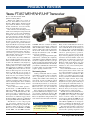
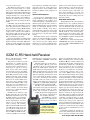
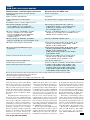
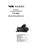
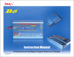
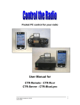
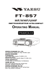
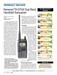
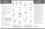
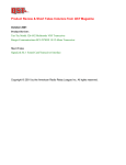
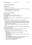
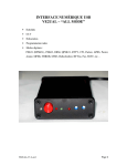
Product Review and Short Takes from QST Magazine
August 2003
Product Reviews:
Yaesu FT-857 MF/HF/VHF/UHF Transceiver
ICOM IC-R5 Hand-held Receiver
Short Takes:
MixW
Copyright © 2003 by the American Radio Relay League Inc. All rights reserved.
PRODUCT REVIEW
Yaesu FT-857 MF/HF/VHF/UHF Transceiver
Reviewed by Rich Arland, K7SZ
QST Contributing Editor
When I was asked to do a review of
the new Yaesu FT-857 transceiver, I
thought, “What timing!” I had been looking at both the FT-857 and its bigger
brother, the FT-897, for several weeks,
trying to decide which one to buy.
Out of the box, the first thing I had to
tackle was mounting the front panel to the
main portion of the radio. Thumbing
through the manual I found, on page
seven, exactly how to do that. The detachable front panel has become an industry
standard with small, mobile transceivers.
In order to remote the control head, you
need to purchase the optional YSK-857
Separation Kit. It is very handy to be able
to bury the main “box” of the radio under
a seat or in the trunk in a mobile installation and have just the small front panel/
control head mounted on the dash. It’s a
convenient, space-saving idea with the
added benefit of being easily concealed
when you leave the vehicle.
On the surface, the newest addition to
the Yaesu HF portable transceiver line
looks a lot like an FT-817 on steroids. That
is where the similarities end (frequency/
mode coverage and menu access not withstanding). The ’857 offers a fully adjustable output from 5 to 100 W on 1.8 through
29.7 MHz, plus 6 meters. Power out on 2
meters is 50 W and power out on 70 centimeters is 20 W. The rig can operate on
voice, CW or data modes. The package is
about twice the size and three times the
weight of the FT-817, so while it may be
suited for a mobile or base station environment, it might be a little on the heavy
side for the backpacker, when combined
with the added weight of a battery, antenna
and accessories.
Yaesu offers three filter options—
the YF-122S, a 2.3 kHz SSB filter, the
YF-122C 500-Hz CW filter, and the
YF-122CN, a 300 Hz CW filter. The
transceiver will accommodate two of
these optional filters, and the installation
instructions are outlined on page 120 of
the manual. Filter call-up is accomplished
by using the Multi Function (MF-n) menu.
The FT-857 is a nice compact package, measuring 2.0×6.1×9.2 inches
(HWD) and weighing 4.6 pounds. The
frequency agility of this rig is amazing.
The receiver covers 100 kHz to 56 MHz,
76-108 MHz, 118-164 MHz and 420-
470 MHz. The user can listen to international shortwave broadcasts, commercial
AM and FM outlets, VHF aeronautical
stations, public safety stations and nearly
all the ham bands from 160 meters
through 70 centimeters (only 222 MHz
coverage is excluded).
The 128 page operating manual is quite
well laid out, considering the complexity
of the FT-857 and the multitude of menus
needed to configure the radio to your particular operating style. The manual is chock
full of pertinent information. It will take
you a while to assimilate the entire manual,
so plan on doing a lot of reading and subsequent “playing” with the radio.
The Learning Curve
Getting comfortable with the controls
on the FT-857 requires a bit of a learning
curve, especially if you are not used to
working with smaller radios utilizing layered menus. A total of 14 buttons control
most of the radio’s features. The FT-857
uses multi-layered menus, accessed by the
function (F) button. Since I had owned the
FT-817 for over a year, the controls and
menus on the FT-857 were almost intuitive.
Press and release the F button and you
go into the multi-function display, a series
of 17 menus controlled by the three MF
buttons directly below the LCD display.
These are adjustments and parameters for
some of the most used features of the radio.
Bottom Line
The FT-857 offers 100 W in a
very compact package. Think of it as
the FT-897 for your car.
Brennan Price, N4QX
Assistant Technical Editor
Many of these multi-function selections
are merely toggles that switch specific features on and off. These are the settings you
may want to change on the fly. Examples
are CW/SSB filter selection, A/B VFO
selection, split frequency operation,
memory storage, speech processor on/off,
keyer memory playback, preamp on/off,
attenuator and noise blanker on/off, and
CTCSS tone encode/decode. Various display options, such as Spectrum Scope
Monitor enable, LCD display size and
metering assignment (Power/SWR/
ALC/S) are also selected through the
multi-function keys.
Press and hold the F button to enter the
menu system, which controls a wide variety of the performance aspects and operating characteristics of the FT-857. This
is where you configure the radio to work
the way you want it to. Menu items include
RF power output selection, keyer setup,
CW/Phone parameters, display color and
brightness, mic gain, repeater shift, keyer
speed, CW pitch and the like. There are
91 menu options available. Each of these
is briefly explained in a matrix, which is a
lifesaver when you are trying to remember all the nuances of this tiny radio.
The FT-857 is loaded with memories.
The QMB (Quick Memory Bank) is used
to quickly store a frequency you might
want to recall in a hurry. You can load
any frequency held in the QMB into one
of the 200 regular memory slots at any
time. While in QMB you can change frequencies, emulating the VFO mode, and
you can also change the operating mode.
The main memory bank is composed of
200 memory slots that can be used to store
your favorite operating frequencies and
[email protected]
From August 2003 QST © ARRL
Table 1
Yaesu FT-857, serial number 3C020019
Manufacturer’s Claimed Specifications
Measured in the ARRL Lab
Frequency coverage: Receive, 0.1-56,
76-108, 118-164, 420-470 MHz; transmit,
1.8-2, 3.5-4, 7-7.3, 10.1-10.15, 14-14.35,
18.068-18.168, 21-21.45, 24.89-24.99,
28-29.7, 50-54, 144-148, 430-450 MHz.
Receive1 and transmit, as specified.
Power requirement: Receive, 1.0 A; transmit, 22 A (100 W output).
Receive, 0.6 A; transmit, 16 A. Tested at 13.8 V.
Modes of operation: SSB, CW, AM, FM.
As specified.
Receiver
Receiver Dynamic Testing
SSB/CW sensitivity, bandwidth not specified,
10 dB S/N: 1.8-30 MHz, <0.2 µV; 50-54 MHz,
<0.13 µV; 144-148, 430-450 MHz, <0.13 µV.
Noise floor (MDS), 500 Hz filter:
Preamp off
1.0 MHz
–127 dBm
3.5 MHz
–130 dBm
14 MHz
–132 dBm
50 MHz
–136 dBm
144 MHz
see note 2
432 MHz
see note 2
AM sensitivity, 10 dB S/N: 0.1-1.8 MHz,
<32 µV; 1.8-30 MHz, <2 µV; 50-54 MHz,
<1 µV; 144-148, 430-450 MHz, not specified.
10 dB (S+N)/N, 1-kHz tone, 30% modulation:
Preamp off
Preamp on
1.0 MHz
1.9 µV
0.91 µV
3.8 MHz
1.6 µV
0.72 µV
50 MHz
0.97 µV
0.48 µV
120 MHz
see note 2
0.41 µV
144 MHz
see note 2
0.42 µV
432 MHz
see note 2
0.51 µV
FM sensitivity, 12 dB SINAD: 28-30 MHz, <0.5 µV;
50-54, 144-148, 430-450 MHz, <0.2 µV.
For 12 dB SINAD:
Preamp off
29 MHz
0.51 µV
52 MHz
0.35 µV
146 MHz
see note 2
440 MHz
see note 2
Blocking dynamic range: Not specified.
Blocking dynamic range, 500 Hz filter:
Spacing
20 kHz
5 kHz
Preamp off/on
Preamp off/on
3.5 MHz
109/106* dB
94*/90* dB
14 MHz
109*/105* dB
94*/88 dB
50 MHz
108*/102* dB
88*/86* dB
144 MHz
note 2/102* dB
note 2/83* dB
432 MHz
note 2/96* dB
note 2/79* dB
Two-tone, third-order IMD dynamic range:
Not specified.
Two-tone, third-order IMD dynamic range, 500 Hz filter:
Spacing
20 kHz
5 kHz
Preamp off/on
Preamp off/on
3.5 MHz
88/88 dB
67/66 dB
14 MHz
87/86 dB
66/65 dB
50 MHz
88/85 dB
67/65 dB
144 MHz
note 2/83 dB
note 2/63 dB
432 MHz
note 2/84 dB
note 2/64 dB
Third-order intercept: Not specified.
Spacing
3.5 MHz
14 MHz
50 MHz
144 MHz
432 MHz
Second-order intercept: Not specified.
modes along with CTCSS information. The
regular memory storage area is where you
would also load any special net/emergency
frequencies, split frequencies for DX operation as well as any nonstandard repeater
splits. Any frequency stored in one of the
200 memory slots can also be tagged alphanumerically to aid in identification.
From August 2003 QST © ARRL
20 kHz
Preamp off/on
+9.2/+1.7 dBm
+4.1/–5.4 dBm
+0.1/–7.1 dBm
note 2/–8.8 dBm
note 2/–6.9 dBm
Preamp on
–134 dBm
–136 dBm
–137 dBm
–140 dBm
–140 dBm
–140 dBm
Preamp on
0.26 µV
0.18 µV
0.19 µV
0.21 µV
5 kHz
Preamp off/on
–18/–25 dBm
–23/–31 dBm
–25/–33 dBm
note 2/–37 dBm
note 2/–34 dBm
Preamp off, +69 dBm; preamp on, +66 dBm.
The FT-857 incorporates the Smart
Search feature from Yaesu’s VHF/UHF
mobiles. In this mode, the rig searches
above your current operating frequency
and locates any active frequencies, storing them in one of the 50 Smart Search
memories. These memories are considered soft memories, because any stored
information will be lost if you initiate a
subsequent Smart Search or go into the
VFO mode. The traveling ham can make
great use of this feature to locate repeaters while driving.
I Can See Clearly Now
The FT-857 also incorporates a Spec-
FM adjacent channel rejection: Not specified.
20 kHz channel spacing, preamp on: 29 MHz, 65 dB; 52 MHz,
65 dB; 146 MHz, 65 dB; 440 MHz, 64 dB.
FM two-tone, third-order IMD dynamic range:
Not specified.
20 kHz channel spacing, preamp on: 29 MHz, 64 dB; 52 MHz,
63 dB; 146 MHz, 61 dB; 440 MHz, 59 dB; 10 MHz channel
spacing, preamp on: 52 MHz, 88 dB; 146 MHz, 87 dB;
440 MHz, 83 dB.
S-meter sensitivity: Not specified.
S9 signal at 14.2 MHz: preamp off, 17 µV; preamp on, 6.6 µV;
52 MHz, preamp off, 14 µV; preamp on, 5.3 µV; 146 MHz,
preamp on, 4.0 µV; 432 MHz, preamp on, 2.6 µV.
Squelch sensitivity: SSB, 1.8-30 MHz, <2.5 µV;
50-54 MHz, <1 µV; 144-148, 420-450 MHz,
<0.5 µV; FM, 28-30 MHz, <0.32 µV; 50-54,
144-148, 430-450 MHz, <0.16 µV.
At threshold, preamp on: SSB, 14 MHz, 1.7 µV; FM,
29 MHz, 0.15 µV; 52 MHz, 0.09 µV; 146 MHz, 0.1 µV;
440 MHz, 0.11 µV.
Receiver audio output: 2.5 W at 10% THD into 4 Ω.
4.0 W at 10% THD into 4 Ω.
IF/audio response: Not specified.
Range at –6 dB points (bandwidth):
CW (500 Hz filter): 386-972 Hz (586 Hz)
USB: 234-2864 Hz (2630 Hz)
LSB: 286-2816 Hz (2530 Hz)
AM: 140-2530 Hz (2390 Hz).
IF rejection: 60 dB; image rejection, 1.8-30, 5054 MHz, 70 dB; 144-148, 430-450 MHz, 60 dB.
First IF rejection, 14 MHz, 124 dB; 50 MHz, 98 dB;
144 MHz, 118 dB; 432 MHz, 129 dB; image rejection,
14 MHz, 100 dB; 50 MHz, 86 dB; 144 MHz, 99 dB;
432 MHz, 72 dB.
Transmitter
Transmitter Dynamic Testing
Power output: HF and 50 MHz: SSB, CW, FM,
100 W, AM, 25 W (carrier); 144 MHz, SSB,
CW, FM, 50 W, AM, 12.5 W (carrier);
430 MHz, SSB, CW, FM, 20 W, AM, 5 W (carrier).
HF and 50 MHz: CW, SSB, FM, typically 102 W high, 3 W low;
AM, typically 20 W high, 1 W low; 144 MHz: CW, SSB,
FM, typically 51 W high, 3.5 W low; AM, typically 12 W high,
1.5 W low; 430 MHz: CW, SSB, FM, typically 19 W high,
2 W low; AM, typically 5 W high, 1 W low.
Spurious-signal and harmonic suppression:
≥50 dB on HF; ≥60 dB on VHF and UHF.
HF, 53 dB; 50 MHz, 61 dB; 144 MHz, 62 dB; 430 MHz, 63 dB.
Meets FCC requirements for spectral purity.
SSB carrier suppression: >40 dB.
53 dB.
Undesired sideband suppression: >50 dB.
56 dB.
Third-order intermodulation distortion (IMD)
products: Not specified.
See Figures 1 and 2.
CW keyer speed range: Not specified.
4 to 59 WPM.
CW keying characteristics: Not specified.
See Figure 3.
Transmit-receive turn-around time (PTT release to
50% audio output): Not specified.
S9 signal, 12 ms.
Receive-transmit turnaround time (tx delay): Not specified.
SSB, 21 ms; FM, 15 ms. Unit is suitable for use on AMTOR.
Composite transmitted noise: Not specified.
See Figures 4 and 5.
Bit-error rate (BER), 9600-baud: Not specified.
146 MHz: Receiver: BER at 12 dB SINAD, 2.8×10⁻³; BER at
16 dB SINAD, 1.4×10⁻⁴; BER at –50 dBm, <1.0×10⁻⁵;
transmitter: BER at 12 dB SINAD, 7.7×10⁻⁴; BER at 12 dB
SINAD + 30 dB, <1.0×10⁻⁵.
440 MHz: Receiver: BER at 12-dB SINAD, 3.3×10⁻³; BER at
16 dB SINAD, 1.5×10⁻⁴; BER at –50 dBm, <1.0×10⁻⁵;
transmitter: BER at 12 dB SINAD, 8.3×10⁻⁴; BER at 12 dB
SINAD + 30 dB, <1.0×10⁻⁵.
Size (height, width, depth): 2.0×6.1×9.2 inches; weight, 4.6 pounds.
Note: Unless otherwise noted, all dynamic range measurements are taken at the ARRL Lab standard spacing of 20 kHz.
*Measurement was noise-limited at the value indicated.
1
Receive sensitivity is reduced below 350 kHz.
2
IPO not available above 56 MHz.
trum Scope Monitor that actually allows
you to “see” activity above and below
your operating frequency, much like a
spectrum analyzer. This feature is active
in the VFO and memory modes. When
activated, the Spectrum Scope Monitor
displays relative signal strength (on the
LCD) on frequencies immediately adja-
cent to your operating frequency in various frequency increments that are selected
based upon the mode in use. This feature
is nice for keeping track of action during
contests and to pinpoint activity on a
given band.
Several scanning options are available
on the FT-857. In the VFO mode the trans-
ceiver will scan either above or below the
VFO frequency (whichever you select),
stopping on active frequencies. In the
memory mode, the transceiver will scan
through the memory channels and halt on
an active frequency. In addition, you can
program the rig to skip selected memory
channels. In the Programmable Memory
From August 2003 QST © ARRL
0
–60
Reference Level: 0 dB PEP
–10
–70
–20
Reference Level: - 60 dBc/Hz
Vertical Scale: dBc/Hz
–80
–30
–90
–40
–100
–50
–110
–60
–120
–70
–130
–80
–10
–8
–6
–4
–2
0
2
4
Frequency Offset (kHz)
6
8
–140
2
10
Figure 1—Worst-case spectral display of
the FT-857 transmitter during two-tone
intermodulation distortion (IMD) testing
on MF and HF. The worst-case third-order
product is approximately 25 dB below
PEP output, and the worst-case fifthorder product is down approximately 40
dB. The transmitter was being operated at
100 W PEP output at 1.85 MHz.
Figure 3—Worst-case CW keying
waveform for the FT-857 showing the first
two dits using external keying. Equivalent
keying speed is approximately 60 wpm.
The upper trace is the actual key closure;
the lower trace is the RF envelope.
Horizontal divisions are 10 ms. The
transmitter was being operated at 100 W
output at 14.2 MHz.
–60
0
Reference Level: 0 dB PEP
–10
–70
–20
–80
–30
–90
–40
–100
–50
–110
–60
–120
–70
–130
–80
–10
–8
–6
–4
–2
0
2
4
Frequency Offset (kHz)
6
8
10
–140
2
Reference Level: - 60 dBc/Hz
Vertical Scale: dBc/Hz
4
6
8
10
12
14
16
18
20
Frequency Sweep: 2 to 22 kHz from Carrier
22
Figure 2—Worst-case spectral display of
the FT-857 transmitter during two-tone
intermodulation distortion (IMD) testing on
VHF and UHF. The worst-case third-order
product is approximately 25 dB below PEP
output, and the worst-case fifth-order
product is down approximately 35 dB. The
transmitter was being operated at 100 W
PEP output at 50.2 MHz.
Figure 4—Worst-case spectral display of
the FT-857 transmitter output during
composite-noise testing on MF and HF.
Power output is 100 W at 14.02 MHz. The
carrier, off the left edge of the plot, is not
shown. This plot shows composite
transmitted noise 2 to 22 kHz from the
carrier.
Scan mode the transceiver will scan
between user prescribed limits. Finally,
the FT-857 has a “Priority Channel” scan
mode whereby the priority channel
(memory channel M-001) is periodically
checked with the transceiver in the VFO
or Memory mode. Once activity on M-001
is detected, the transceiver will pause on
the priority channel.
This optional cable performs level conversion for proper serial port to radio operation. Yaesu does not produce any CAT
software, but there are several sources on
the Internet.
The CAT’s Out of the Bag
Yaesu’s CAT System provides a
method of controlling various aspects of
the FT-857 via your computer. By using
third-party software packages like contest
logging software, your computer can
communicate with the FT-857 without any
redundant operator intervention, making
contesting a real pleasure. In order to use
the CAT System, you’ll need the optional
CT-62 cable, which interfaces your
computer’s RS-232 port to the CAT/Linear jack on the rear apron of the FT-857.
From August 2003 QST © ARRL
On-Air Operations
Reading the manual, perusing the
specifications and dissecting the Lab test
results is fine, but this only tells part of
the story. You can have a rig with outstanding specs, but if you are not comfortable using it, you’re not going to be
satisfied and you are not going to have
any fun with the radio.
Thankfully, the FT-857 is a dream rig
to use. One operational feature I really
like is the ability to set the LCD screen
color to change when you change bands,
band segments and/or modes. This means
you can select different colors for FM,
SSB, DATA and AM, or color-code band
segments like QRP calling frequencies,
4
6
8
10
12
14
16
18
20
Frequency Sweep: 2 to 22 kHz from Carrier
22
Figure 5—Worst-case spectral display of
the FT-857 transmitter output during
composite-noise testing on VHF and UHF.
Power output is 20 W at 432.02 MHz. The
carrier, off the left edge of the plot, is not
shown. This plot shows composite
transmitted noise 2 to 22 kHz from the
carrier.
DX watering holes, and simplex or repeater sub-bands, making it a lot easier
to navigate through the memory maze.
On-air testing with the FT-857 provided
me with many hours of fun on the QRP
bands, and some serious DXing, using
higher power, on the low end of 20 meters.
Our local ARES group is quite active,
offering three weekly nets on two local
repeaters. I used the ’857 to check into several of these nets and to work some folks
via local 2-meter and 70-centimeter
repeaters. I received great audio reports on
both SSB and FM using the factory default
settings.
CW operation provided a couple of
twists. The FT-857 does not feature full
break-in (QSK) keying, or anything really close to it. The T/R switchover is adjustable from 3000 ms down to 30 ms, but
even at that, the CW keying is not full
break-in. In addition, the T/R relay (yes,
the FT-857 uses a relay to switch between
transmit and receive) chatters like mad at
speed. So I adjusted the T/R changeover
to around 300 ms, which delays the transmitter between characters at 15 WPM and
higher. This seems to provide the best
trade-off between a chattering relay and
receiver recovery time.
One very nice feature is the TX/BUSY
indicator, just to the left of the main tuning knob. This indicator glows green
when the squelch is open, red during
transmit and bright blue when the incoming signal is zero-beat with the IF passband in the CW mode (with the IF shift
off). This makes easy work of getting exactly on the transmitting station’s frequency. This is great for those of us who
lack perfect pitch. In addition, when the
radio is in the FM mode, this indicator
will glow blue when you are receiving a
signal with a CTCSS/DCS encoded tone
that matches the one to which your trans-
ceiver is set. Nice touch!
The ability to load up to three “canned”
messages for instant reply via a single
press of one of the three Multi-Function
buttons (Ply1, Ply2, Ply3 in multi-function
menu MFo) is a great feature. You can thus
configure the keyer as a contest keyer (although it won’t handle serial numbers),
reducing the number of boxes you have
to drag along when operating portable or
mobile.
CW DXing using the IF shift and Clarifier (RIT) controls on the FT-857 proved
to be quite pleasant. The combination of
these two features and the 500-Hz Collins
mechanical filter enabled me to snag a
couple of new countries in the middle of
large pileups. Split operation is a breeze
using the dual VFOs on the FT-857. The
DX can run but they can’t hide!
Receiver performance is similar to but
slightly degraded from Yaesu’s FT-897
model, reviewed in the May 2003 issue
of QST. As a rule, dynamic range (blocking and third order IMD) were slightly
worse. However, the third-order and second-order intercept points improved
slightly from the ’857’s bulkier older
brother. See Table 1 for the complete test
results.
Quirks and Annoyances
No rig is perfect, and the FT-857 is no
exception. Here are a few thoughts on how
Yaesu could improve the package. A set
of laminated plastic cards listing the 91
different menu system items and the 17
different multi-function options would be
useful as a field guide. Having a set of
small, readily available cheat sheets
would make life a whole lot easier on the
user and save valuable space and weight
by not having to carry the entire manual
around.
Then there is the dc power cord, which
ought to be redesigned. Many manufacturers use no. 10 or 12 AWG red/black
“zip cord” for dc power cabling. Yaesu
decided to use separate red/black wires
with a plug on one end and in-line fuse
holders on the other. Unless you remove
the fuse holders or lop off the plug that
mates to the radio, there is no practical
way to run this power cord inside a vehicle. Yaesu should use “zip cord” and
provide the fuse holders for the user to
install after the power cabling has been
run in the vehicle.
Affordable and Portable
Would I buy this radio? In a heartbeat!
The FT-857 is a very capable rig designed
with the mobile/portable ham radio operator in mind. The folks at Yaesu have
done their homework and given us a rig
that offers outstanding performance with
100 W of RF in a very small package.
Yaesu designers have taken up the challenge to improve on their tremendously
successful FT-817 and the result is the FT857. Well done, Yaesu!
Manufacturer: Vertex Standard USA,
10900 Walker St, Cypress, CA 90630; tel
714-827-7600; www.vxstdusa.com.
Price: $849.95.
ICOM IC-R5 Hand-held Receiver
Reviewed by Brennan Price, N4QX
Assistant Technical Editor
The past few years have seen the
introduction of a number of handheld receivers. Some have more features than others, and buyers have a
wide range of options to choose
from. A few of the more sophisticated models even have the ability
to receive the most popular Amateur
Radio HF operating modes, single
sideband and CW. Some amateurs
findcarrying a comprehensive handheld receiver useful. While many
transceivers have multiple watch
functions and multiple VFOs, sometimes they are poor substitutes for a
completely separate receiver. As a
result, a number of amateur manufacturers have added hand-held receivers to their lines.
ICOM’s latest offering is the
IC-R5. About the size of its latest
multiband hand-held receiver, the
IC-T90A, the ’R5 is not among the
CW and single-sideband capable
models. Nevertheless, at its size
and price, it is an impressive machine, scanning and sounding
AM, narrowband FM and broadcast FM signals with speed and
ease. From the AM broadcast
band, through the shortwaves, and
into the VHF and UHF amateur,
aviation, and public service bands,
the IC-R5 offers comprehensive coverage
from 150 kHz to 1300 MHz, cellular frequencies excluded.
The first impression of the radio is,
“It’s all speaker.” Merely seven front
panel keys—all on top of the speaker and
below the LCD and the 10-character
LCD readout, two side panel keys, and a
DIAL constitute the user’s interface with
the radio. The user’s manual does a credible job explaining their function, however, and I found the limited controls
easy to use. All tuning is done through
the DIAL, with each click executing a
band-specific tuning step. Large steps of
1 MHz are accomplished by holding the
F side button while clicking the DIAL .
The ’R5 comes with two Ni-Cd size
AA batteries and a plug-in wall charger.
The initial charging routine is a little
tricky, and not nearly as intuitive as
loading the batteries and plugging in
the charger. A quick read of
the manual is advisable.
The BAND key toggles
between 12 different frequency bands, each with a
Bottom Line
ICOM’s IC-R5 is tiny,
inexpensive and simple,
and it’s a nice station
accessory for amateurs
looking for these qualities.
distinct and adjustable tuning step. The
DIAL controls frequency selection, while
the and keys control volume level
from the 0.1-W speaker. A thousand standard memory channels are available and
may be assigned to any of 18 memory
banks. Twenty-five pairs of band edge
memories can delineate frequently
scanned band segments, such as the
145.1-145.5 MHz 2-meter repeater segment. Both manual tuning and scanning
can be performed in VFO and memory
modes. United States television audio frequencies and weather frequencies are
preprogrammed and have special displays.
Both the input and the output of an Amateur Radio repeater (or any other repeater)
can be monitored through the receiver’s
duplex operation feature. Briefly, this is
accomplished by setting the offset, enabling duplex mode, and pressing the SQL
button to monitor the repeater input directly. The actual procedure for setting the
offset and turning the duplex mode on is
somewhat convoluted; there are eight
steps of button pushing and DIAL turning
between the setting of the output frequency and when the input frequency can
be monitored at the touch of a button. Also
of interest to amateurs is the ’R5’s ability
to detect and decode CTCSS tones and
DCS codes.
Particularly useful is the manual’s frequency table, which lists the audio frequencies for television channels in the United
From August 2003 QST © ARRL
Table 2
ICOM IC-R5, serial number 0601263
Manufacturer’s Claimed Specifications
Measured in the ARRL Lab
Frequency coverage: Receive, 0.15-822; 851-867;
896-1310 MHz.
Receive, as specified.1
Modes of operation: FM, WFM, AM.
As specified.
Power requirements: 0.17 A (max audio),
6 V dc.
0.15 A (max volume, no signal), tested at 6.0 V dc.
Size (HWD): 3.4×2.3×1.1 inches; weight, 6.5 ounces.
AM sensitivity (10 dB S/N): 0.5-5 MHz,
1.3 µV; 5-30 MHz, 0.71 µV; 118-136 MHz,
222-247 MHz, 0.56 µV; 247-330 MHz, 0.71 µV.
AM, test signal modulated 30% with a 1-kHz tone,
10 dB (S+N)/N: 1.0 MHz, 1.1 µV; 3.8 MHz, 0.58 µV;
53 MHz, 0.4 µV; 120 MHz, 0.46 µV; 146 MHz,
0.41 µV; 440 MHz, 0.6 µV;
FM narrow sensitivity (12 dB SINAD): 1.6-5 MHz,
0.32 µV; 5-118 MHz, 0.2 µV; 118-247 MHz,
0.18 µV; 247-330 MHz, 0.2 µV; 330-470 MHz,
0.18 µV; 470-1000 MHz, 0.28 µV; 10001310 MHz, 0.35 µV.
FM narrow, 12 dB SINAD: 29 MHz, 0.17 µV; 52 MHz, 0.14 µV;
146 MHz, 0.15 µV; 222 MHz, 0.14 µV; 440 MHz, 0.2 µV;
906 MHz, 0.23 µV; 1270 MHz, 0.28 µV.
FM wide sensitivity (12 dB SINAD): 76-108 MHz,
0.89 µV; 175-222 MHz, 0.71 µV; 470-770 MHz, 1.0 µV.
FM wide, 12 dB SINAD: 100 MHz, 0.84 µV.
FM adjacent channel rejection: Not specified.
20 kHz channel spacing: 29 MHz, 56 dB; 52 MHz, 57 dB;
146 MHz, 51 dB; 222 MHz, 49 dB; 440 MHz, 53 dB;
906 MHz, 57 dB; 1270 MHz, 49 dB.
FM two-tone, third-order IMD dynamic range:
Not specified.
20 kHz channel spacing: 29 MHz, 48 dB; 52 MHz, 49 dB;
146 MHz, 47 dB; 222 MHz, 50 dB; 440 MHz, 47 dB;
906 MHz, 55 dB; 1270 MHz, 49 dB.*
10 MHz channel spacing: 52 MHz, 57 dB; 146 MHz,
69 dB; 440 MHz, 59 dB.
Squelch sensitivity (threshold): Not specified.
At threshold: FM, 29 MHz, 0.34 µV; 52 MHz, 0.38 µV;
146 MHz, 0.34 µV; 222 MHz, 0.38 µV; 440 MHz,
0.38 µV; 906 MHz, 0.8 µV; 1270 MHz, 1.1 µV.
Audio output: 0.1 W at 10% THD into 8 Ω.
0.125 W at 8% THD into 8 Ω2
IF/audio response: Not specified.
Range at –6 dB points (bandwidth): AM: 306-3562 Hz (3256 Hz).
Spurious and Image rejection: Not specified.
IF: 29 MHz, 75 dB; 52 MHz, 31 dB; 144 MHz, 71 dB;
222 MHz, 21 dB; 440 MHz, 53 dB; 906 MHz, 61 dB;
1270 MHz, 59 dB; Image: 29 MHz, 56 dB; 52 MHz,
53 dB; 146 MHz, 99 dB; 222 MHz, 43 dB, 440 MHz,
74 dB; 906 MHz, 33 dB; 1270 MHz, 9 dB.
Except as noted, all dynamic range measurements were taken using the ARRL Lab standard spacing of 20 kHz.
*Measurement was noise-limited at the value indicated.
1Sensitivity degrades slightly below 500 kHz.
2Volume control is stepped—the next higher step produced 14% THD.
States and other parts of the world. The 68
United States channels are programmed
into a special band at the factory, but the
table is a terrific ready-reference for travel
abroad. The table also includes widely used
frequencies in the Aviation, General Mobile, Family Radio, and Business Radio
Services.
Programming and scanning is quite easy.
In fact, the two can be combined through
an automatic memory write function, which
can store up to 200 active frequencies automatically as a band is scanned. This is
useful when you visit a place without a frequency list or repeater directory handy. Programming a frequency into a standard
memory channel is as simple as tuning the
frequency in the VFO, pressing the S.MW
button for one second, selecting the
memory channel number, and pressing the
From August 2003 QST © ARRL
S.MW button again. The receiver makes
efficient use of the limited controls it has.
Listening to the ’R5 is pleasant. The
prominent speaker cranks out 0.125 W at
8% THD into 8 Ω, according to ARRL Lab
test results. The sensitivity measurements
meet and in some cases exceed what one
would expect from a handheld receiver in
this price class, and the dynamic range
measurements are about as expected. All
VHF and UHF stations that I expected to
hear from my location were indeed heard
by the ’R5, and I was pleasantly surprised
with its HF performance. See Table 2 for
the ARRL Lab’s measurements.
The ’R5 comes with a SMA-threaded
rubber duck antenna. Of course, such an
antenna is ideal for use at higher VHF and
UHF frequencies. Only the strongest
meduimwave and shortwave stations can
be adequately detected by this antenna, but
shortwave listeners know that a substantial external antenna is imperative for receivers—even hand-helds. Nevertheless,
I received Hartford-area AM broadcasters and even transmissions from Radio
Canada International’s Sackville, New
Brunswick, facility with no difficulty.
The IC-R5 is a solid offering, easily receiving strong broadcast signals and rapidly scanning standard or user-designated
band segments. Its portability and price are
attractive, and hams unwilling or not needing to spend the money for additional
modes may find the ’R5 a useful accessory.
Manufacturer: ICOM America, 2380
116th Ave NE, Bellevue, WA 98004;
tel 425-454-8155; fax 425-4541509; www.icomamerica.com. Price:
$199.95.
SHORT TAKES
MixW
Is it possible to discuss a multifaceted piece of software in
a single QST page? MixW Windows is essentially one-stop shopping for Amateur Radio digital operating. It’s difficult to do
justice to the “Swiss Army Knife” of digital software in less
than 800 words.
What Can’t It Do?
Assuming you own a sound-card-equipped Windows PC and
an appropriate sound-card interface, MixW gives you the ability to send and receive RTTY, CW, PSK31, Hellschreiber,
MFSK16, FSK31, PSK63, Throb, MT63, SSTV, packet (HF
and VHF) and AMTOR. You can also receive PACTOR-I and
fax with MixW.
MixW will “talk” to your transceiver if it is CAT compatible, which many are these days. This means you can manipulate your rig from within MixW. With software such as
PCAnywhere, you can even do this remotely. MixW can also
interface with your antenna rotator.
MixW incorporates a sophisticated logging program that
includes a “contest mode” with configurations for a number of
popular digital contests. When you click on a call sign in the
receive window, MixW enters the call into the log and displays
the country information according to the prefix. MixW will
export to ADIF and Cabrillo formats. And, yes, it prints QSLs
and QSL labels.
As they say in the TV commercials, “Wait! There’s more!”
MixW will function as a “voice keyer” for contest operating. It
can grab spots from your local DXcluster via packet radio or
the Internet. MixW will even monitor and decode the NCDXF/
IARU CW propagation beacons (your PC needs to have a very
accurate clock for this function to work properly).
On the Air with MixW
After two months, I am still exploring the features of MixW,
but what I’ve seen so far is impressive. With the selectable waterfall, spectrum and tuning displays, MixW is quite easy to op-
Figure 1—PAØWCH sends a picture of himself while making an
MFSK16 contact with PY7MG.
Steve Ford, WB8IMY
From August 2003 QST © ARRL
erate, regardless of mode. Even digital modes as notoriously difficult to tune as HF packet and MFSK16 yielded quickly to MixW.
Speaking of MFSK16, one of the new aspects of this mode
is the ability to send images at any time during a QSO. The
practice is controversial among US amateurs because, depending on how you interpret Part 97, transmissions with image
content may be illegal within the so-called CW/digital subbands
(which is why traditional analog SSTV QSOs are conducted
in the phone portions of the bands). I have already seen a number of these image-added MFSK16 QSOs taking place. MixW
automates the process in a clever way. If you are copying text
and the operator suddenly begins sending an image, MixW
automatically opens a tiny window, displays the picture (see
Figure 1) and then returns to the text mode.
PSK31 operation with MixW was a joy. You can “bookmark”
stations in the tuning display and even scan for signals throughout the passband. The tuning indicator analyzes signal characteristics and provides RST reports on the fly (a handy feature).
MixW did a fine job copying RTTY. Its performance might
fall a little short of the highly praised MMTTY software, but it
is close. Visual modes such as SSTV and Hellschreiber worked
very well. Hellschreiber was particularly fun with MixW. See
Figure 2. As with all amateur software, I found that performance in the CW mode is most reliable with perfect fists and
strong signals.
Conclusion
To experience MixW with minimal investment, download and
test-drive the fully functional 15-day version. You can download
it from Jim Jaffe, WA2VOS, at www.nvbb.net/~jaffejim/
MixWpage.htm, or from the MixW site at www.mixw.net. The
registered version will set you back $50, which is not bad at all
for such a highly capable application.
System requirements: Pentium 166 or faster PC running
Windows 98, ME, NT, 2000 or XP with a 16-bit SoundBlastercompatible sound card.
Figure 2—WA9HCZ and K5WTA enjoying a Hellschreiber QSO.
QST Editor
[email protected]