1
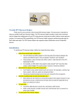
ProtoQ FPV Harness Helper Thank you for your purchase of the ProtoQ FPV Harness Helper. The FPV Harness Helper provides a quick and convenient way to change the configuration of your FPV wiring harness using easy to solder surface mount pads and jumpers. For maximum OSD compatibility, the FPV Harness Helper supports passthrough for both video and audio. The FPV Harness Helper also supports power distribution across all attached devices. Installation The following directions are intended for a beginner level user. For advanced users, see the reference photos at the end of this document. 1. Determine passthrough configuration. Note two solder jumpers on the top side of the board, between the camera and OSD/VTx ports. They are labeled “XosdVid” and “XosdAud”. These jumpers, when shorted, pass either audio or video directly to the VTX, bypassing the OSD. For example, an OSD which only supports video should *not* have the video jumper solder bridged. The audio jumper, however, should be soldered. 2. Determine the pinouts of your FPV components. You’ll need to know what function each wire serves. For example, a camera may have a power, video out, audio out and ground lead. This pinout should be easily found in the user manual for the component. 3. Strip the insulation back on each wire by about 0.1”. Wires which do not need to be connected should not be striped, however it may be necessary to put a small amount of heat shrink around the exposed end of the wire to prevent a short. 4. Tin each wire. Touch the soldering iron to each wire. Hold it on for about a half second. With the iron still on the wire, feed a small amount of solder into the wire until the bare wire is covered in a shiny coat of solder. 5. Tin each pad of the Harness Helper. Touch the soldering iron to each pad on the FPV Harness Helper. Hold it on for about a half second. With the iron still on the pad, feed a small amount of solder in until a shiny “bubble” of solder has formed on top of the pad. 6. Solder each wire to the appropriate location on the FPV Harness Helper. See the reference images below to determine where to connect each wire. Since the FPV Harness Helper and wire have both been tinned, there is no need to add more solder to the connection. Place the wire on top of the solder bubble on the FPV Harness Helper. Hold the soldering iron on the wire and solder bubble until the bubble becomes molten. Hold the iron in the bubble for a half second, then continue holding the wire in place while removing the iron. 7. Use the included heatshrink tubing to cover the assembled board. Design/Contact Information Design by Chris Seto [email protected] Reference Figures Below Reference Figures Figure 1. Top side, FPV Harness Helper, CAD View Figure 2. Top View, FPV Harness Helper, Actual Board Figure 3. Bottom View, FPV Harness Helper, Actual Board