1
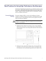
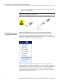
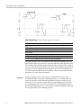
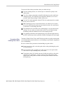
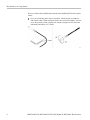
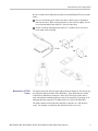
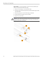
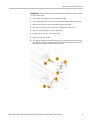
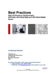
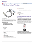
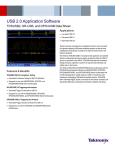
xx
ZZZ
DSA70000D, DPO70000D/DX,
MSO70000C/DX, DSA70000C,
DPO70000C, and DPO7000C
High Performance Oscilloscopes
Best Practices Manual
*P071298901*
071-2989-01
xx
ZZZ
DSA70000D, DPO70000D/DX,
MSO70000C/DX, DSA70000C,
DPO70000C, and DPO7000C
High Performance Oscilloscopes
Best Practices Manual
www.tektronix.com
071-2989-01
Copyright © Tektronix. All rights reserved. Licensed software products are owned by Tektronix or its subsidiaries
or suppliers, and are protected by national copyright laws and international treaty provisions.
Tektronix products are covered by U.S. and foreign patents, issued and pending. Information in this publication
supersedes that in all previously published material. Specifications and price change privileges reserved.
TEKTRONIX and TEK are registered trademarks of Tektronix, Inc.
Contacting Tektronix
Tektronix, Inc.
14150 SW Karl Braun Drive
P.O. Box 500
Beaverton, OR 97077
USA
For product information, sales, service, and technical support:
In North America, call 1-800-833-9200.
Worldwide, visit www.tektronix.com to find contacts in your area.
Best Practices for Using High Performance Oscilloscopes
Optimizing and maintaining the performance of your Tektronix product is critical
to your success. This document summarizes the Best Practices for using Tektronix
DSA70000C/D, DPO70000C/D/DX, MSO70000C/DX, and DPO7000C Series
products. Additional technical, application, and service information is available
at the www.tektronix.com Web site.
Preventing Electrostatic
Discharge
Electrostatic discharge (ESD) is a concern when handling any electronic
equipment. All Tektronix instruments and probes are designed with robust ESD
protection. However, large discharges of static electricity applied to the signal
inputs may damage the equipment.
CAUTION. A direct static discharge can damage the input circuitry of the
instrument. To avoid damage, follow these techniques to prevent electrostatic
discharge to the instrument:
1. Discharge the static voltage from your body. To do so, wear a grounded
antistatic wrist strap when you connect and disconnect cables and adapters.
Your instrument provides a convenient ground connection on the front panel
for this purpose.
2. Discharge the static voltage from all cables before connecting them to the
instrument or to the device under test (DUT). Before you attach the cable
to the instrument, you can momentarily ground the center conductor of the
MSO70000C/DX, DPO70000C/D/DX, DSA70000C/D, DPO7000C Best Practices
1
Best Practices for Using High Performance Oscilloscopes
cable, or you can connect a 50 ohm termination to one end before attaching
the cable to the instrument.
NOTE. A cable that is left unconnected on a bench can develop a very large static
charge that can damage the instrument.
Signal Path Compensation
and Instrument Calibration
Signal Path Compensation (SPC) corrects for DC inaccuracies caused by
temperature variations or by long-term drift. Remove all channel input
connections and run the SPC routine occasionally or whenever the ambient
temperature of the instrument has changed by more than 5 °C (9 °F) to assure that
acquisitions are made with a high degree of accuracy.
Adhere to a regular schedule of calibration of the instrument. A Tektronix
Calibration Service plan is the most efficient way to ensure specified performance
over the lifetime of your Tektronix instrument. The service plan also guarantees
continuous compliance with international quality and traceability standards.
Contact your Tektronix Representative or refer to the www.tektronix.com Web
site for instrument calibration services.
2
MSO70000C/DX, DPO70000C/D/DX, DSA70000C/D, DPO7000C Best Practices
Best Practices for Using High Performance Oscilloscopes
Instrument Temperature
and Clearance
The instrument must have 3 inches of clearance on both the left and right sides for
proper ventilation. The air temperature around the instrument must be between
+5 °C and +45 °C (+41 °F and +113 °F).
Deskew Channels
Use the Deskew/Attenuation control window to compensate for propagation
delays of different length probes and to set the input/output ratio of any external
attenuation or gain between the signal and input channels. Deskew relates directly
to the vertical settings, so it is important to deskew at the vertical settings at which
measurements will be taken or within the same amplifier range. Refer to the
Deskew/Attenuation Control Window topic in the Online Help of the instrument
for information on the deskew and attenuation procedures.
Operating System Restore
The instrument contains an operating system restore file on a separate partition of
the hard drive. The preferred method to restore the operating system is to use the
hard disk restore file. For more information, see the instrument user manual.
Updates to Firmware and
Applications
You should regularly check for updates to the instrument firmware and
applications of your Tektronix products. Access the www.tektronix.com/software
Web page and search for the model number of your instrument (or application) to
check for updates.
Windows Applications and
Hard Drive Maintenance
The Windows instrument is highly specialized to execute the oscilloscope
application that is its primary function. It also provides the capability to run other
Windows compatible applications in the Windows Desktop. Some 3rd Party
applications (not from Tektronix) are included with the Windows instrument
for your convenience, such as a CD creation program. Caution should be taken
when adding new 3rd Party programs to the Windows instrument so that the 3rd
Party program will not interfere with the operation of the primary oscilloscope
application and its supporting software architecture.
Windows Shut Down
Procedures
The Windows instrument has specialized shut down procedures that assure the
integrity of the system structure and data when powering down the instrument.
Use the Shutdown command in the File menu of the oscilloscope, or the Shut
Down command in the Start menu when powering down the instrument. Avoid
abrupt shutdowns caused by pushing the On/Standby button for 5 seconds or
by removing the power cable.
Allow the instrument to complete its Start-up routine before shutting down the
oscilloscope. Do not power off the instrument before the Windows system is fully
loaded and running, as this action will harm the Windows System files.
MSO70000C/DX, DPO70000C/D/DX, DSA70000C/D, DPO7000C Best Practices
3
Best Practices for Using High Performance Oscilloscopes
Taking Acquisitions and
Measurements
Here are suggestions from Tektronix Application Engineers on the best practices
to follow when you take measurements:
Make sure that the cables are capable of the bandwidth that is being measured.
Torque the SMA connectors to 8 in-lbs for proper power measurements.
Tighten the screw on high bandwidth probes and on the TCA-292 to avoid
connector float that can disturb the signal.
Push the Default Setup button to begin from a known state when configuring
the instrument for the acquisition.
Verify that the signal is properly characterized by using the highest Horizontal
Resolution possible.
Verify that the signal is maximized from the bottom of the screen to the top
of the screen.
Use the Fine adjustment with the Vertical controls to get the best resolution.
Use a constant sample rate if the acquisition must be at the full sample rate
as the time base is adjusted.
Check the surrounding environment of the instrument for interfering signal
sources.
Keep the lead lengths between the DUT and the instrument input connector
as short as possible.
Save relevant waveform data files and screen shots to allow you to go back
and verify measurements.
Maximum Instrument Input
Voltage
The maximum instrument input voltages are as follows:
MSO70000DX and DPO70000DX Series
≤1.2 VFS:
±5 V absolute maximum input
>1.2 VFS:
8.0 V. Limited by maximum Vterm current and the attenuator power rating at maximum
temperature
DSA70000D and DPO70000D Series
±600 mV centered on the offset voltage (±4.6 V maximum)
±1.5 V relative to the termination bias (30 mA maximum)
MSO70000C, DPO70000C, and DSA70000C Series
10 mV/div to 99.5 mV/div: 1 VRMS
100 mV/div to 1 V/div: 5 VRMS
4
MSO70000C/DX, DPO70000C/D/DX, DSA70000C/D, DPO7000C Best Practices
Best Practices for Using Probes
DPO7000 Series
1 MΩ: ±150 V CAT I, derate at 20 dB/decade to 9 VRMS above 200 kHz
50 Ω: 5 VRMS with peaks less than ±24 V
NOTE. When using probes on the measurement inputs, do not exceed the
instrument or probe ratings. Refer to the user manual for additional information
available on the www.tektronix.com/manuals Web page.
Best Practices for Using Probes
For P7500 Series probes, the maximum nondestructive input voltage is: ±15 V
(DC + peak AC).
For P7600 Series probes, the maximum nondestructive input voltage is ±8 V (DC
+ peak AC), with tip adapter.
CAUTION. To avoid damage to the probe inputs, do not apply more than maximum
nondestructive input voltage (DC + peak AC) between each input, or between
either probe input and ground.
Refer to the probe user or instruction manual for additional information available
on the www.tektronix.com/manuals Web page.
ESD and Probes
To avoid ESD damage to the probe, always use an antistatic wrist strap and
work at a static-approved workstation when you handle the probe. (See page 1,
Preventing Electrostatic Discharge.)
TriMode Probes
Dynamic Range. The differential signal ranges (with DC coupled) are as follows:
P7513 and P7516
P7520A
P7630
±0.750 V at 5X attenuation
±0.625 V at 5X attenuation
CA: 1.2 Vpp
±1.75 V at 12.5X attenuation
±1.60 V at 12.5X attenuation
TA: 10 Vpp
An example operating voltage window (shown next) defines the maximum
voltage that you can apply to each input, with respect to earth ground, without
saturating the probe input circuitry. A common-mode voltage that exceeds the
operating voltage window may produce an erroneous output waveform, even
when the differential-mode specification is met.
MSO70000C/DX, DPO70000C/D/DX, DSA70000C/D, DPO7000C Best Practices
5
Best Practices for Using Probes
Offset Voltage Range. Offset voltage ranges are as follows:
P7600
±4 V
P7513, P7516, and P7520A
-1.5 V to +2.5 V for Differential mode
P7513, P7516
-2.0 V to +4.0 V for Single-Ended and Common mode (ground referenced)
P7520A
-1.8 V to +3.4 V for Single-Ended and Common mode (ground referenced)
The Offset Voltage Control, accessible from the attached instrument, allows the
probe dynamic range to be effectively moved up and down within the limits of the
offset voltage range and the operating voltage window. When the offset voltage is
set to zero volts and the input signal is zero volts (analog channel inputs shorted to
ground, not open), the displayed signal should be zero volts. If a noticeable zero
volt offset is present under the above conditions, a Probe Cal operation should be
performed. (See your probe user manual.)
Soldering
6
To prevent damage to the circuit board or circuit board connections due to
accidental movement of the probe and soldered leads, we recommend that you
secure the tip to the circuit board using the adhesive tip tape provided in your
accessory kit. You can also use other materials such as Kapton tape or hot glue.
To avoid damage to the tip or to the circuit under test, avoid applying excessive
heat from the soldering iron. Use a low wattage, temperature-controlled soldering
iron and appropriately sized soldering iron tip.
MSO70000C/DX, DPO70000C/D/DX, DSA70000C/D, DPO7000C Best Practices
Best Practices for Using Probes
You need to follow these precautions when you solder the tips:
For best soldering results, use a microscope to examine the quality of the
solder joints.
Use a low-wattage, temperature-controlled soldering iron and a small-mass
soldering iron tip. The soldering iron temperature should be set as low as
possible, while still providing a reliable solder joint.
Use SAC305 solder (included with the P7500 wire replacement kit) to attach
the tip wires to the DUT.
When replacing tip wires or axial-lead resistors, use solder wick to remove
the excess solder from the probe tip circuit board via holes. Be careful not to
overheat the via and damage the board.
The attachment wires should be bent symmetrically to vary the interconnect
spacing. Use care when you solder a tip to a DUT to avoid inadvertently
desoldering either the attachment wires or the damping resistor.
For optimum performance and signal integrity, keep the lead length between
the DUT and the tip as short as possible, and the lead lengths the same length.
Precautions When
Handling Probe Cables
Tektronix P7600, P6700, P7300, and P7500 Series probes are quality measurement
tools and should be treated with care to avoid damage or performance degradation
due to mishandling.
Be sure to follow these precautions when handling any probe cables:
Do not excessively pull or twist the probe cables when positioning the probe
for measurements.
Never crush the cable, as might occur when you run over the probe with a
chair wheel or drop something heavy on the cable.
To maximize probe life, limit the amount of cable twist relative to the probe
control box to ±180 degrees. Always uncoil a probe cable gently before
applying the twisting forces needed to orient the probe head for connection
to the probe tip.
MSO70000C/DX, DPO70000C/D/DX, DSA70000C/D, DPO7000C Best Practices
7
Best Practices for Using Probes
Be sure to follow these additional precautions when handling P7500 Series probe
cables:
Never over-bend the probe main or tip cables, which can put a permanent
kink into the cable. When storing the probe, do not coil it too tightly. It is best
to use the protective foam carrying case which is designed to not exceed the
minimum bend radius of 2.5 inches.
8
MSO70000C/DX, DPO70000C/D/DX, DSA70000C/D, DPO7000C Best Practices
Best Practices for Using Probes
Be sure to follow these additional precautions when handling P6700 Series probe
cables:
Never over-bend the probe main or tip cables, which can put a permanent
kink into the cable. When storing the probe, do not coil it too tightly. Do not
exceed the minimum bend radius of 1 inch for either cable.
Do not exceed the minimum bend radius of 2.5 inches side-to-side with a
probe main cable laying flat.
Maintenance of P7500
Probes
The input to the probe body, the part of the probe that connects to the various tips,
was designed with replaceable G3PO RF bullets. These RF bullets are similar
in function to SMA barrel connectors. Since the P7500 Series probes can be
used with multiple interchangeable tips, there is the possibility of wearing out or
damaging the input connector. To address this issue, replace the RF bullets.
The bullet contacts in the probe body should be replaced every 200 insertion
cycles. For medium use situations, this should be about once a year.
MSO70000C/DX, DPO70000C/D/DX, DSA70000C/D, DPO7000C Best Practices
9
Best Practices for Using Probes
Remove Bullets. To remove the bullets, use the removal tool (Tektronix part
number: 003-1896-00) and follow these steps:
1. Squeeze the tool plunger to extend the holder tangs.
2. Insert the removal tool into the probe body so that the holder tangs surround
one of the bullets.
3. Release the plunger to secure the holder tangs on the bullet.
4. Gently pull the tool outward to remove the bullet.
5. Repeat for the other bullet.
CAUTION. If you cannot extract the bullets with the bullet removal tool, use fine
needle-nosed pliers and a magnifying glass or microscope. Be careful not to
damage the probe body with the pliers.
10
MSO70000C/DX, DPO70000C/D/DX, DSA70000C/D, DPO7000C Best Practices
Best Practices for Using Probes
Install Bullets. When both bullets have been removed, install new bullets. To do
so, follow these steps:
1. Squeeze the tool plunger to extend the holder tangs.
2. Insert a new bullet into the tool so that the holder tangs surround the bullet.
3. Release the plunger to secure the holder tangs on the bullet.
4. Insert the tool into the probe body and seat the bullet in the recess.
5. Squeeze the tool plunger to release the bullet.
6. Gently pull the tool out of the probe body.
7. Repeat for the other bullet.
8. Test that the bullets are installed correctly by connecting and then removing
an accessory solder tip to the probe head. Inspect the probe head and verify
that the bullets remain seated in the probe head.
MSO70000C/DX, DPO70000C/D/DX, DSA70000C/D, DPO7000C Best Practices
11