1
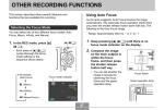
PS-425
Pitot-Static/Air Data Tester
OPERATION AND MAINTENANCE
MANUAL
Preston Pressure LLC
prestonpressure.com
Revision 2, November 1, 2013
PRESTON PRESSURE LLC
PS-425
USER AND MAINTENANCE MANUAL
TABLE OF CONTENTS
Page
Warranty and Liability Statement---------------------------------------------------- 2
1. General Information------------------------------------------------------------------2. Specifications -----------------------------------------------------------------3. Front Panel Layout------------------------------------------------------------4. Front Panel Description -------------------------------------------------------
3
4
5
6
2. Theory------------------------------------------------------------------------------------- 7
3. Operation -------------------------------------------------------------------------------- 8
1. Preliminary Information ------------------------------------------------------- 8
2. Error Codes --------------------------------------------------------------------8
2. Pre-testing ----------------------------------------------------------------------- 8
3. Testing Aircraft Pitot System ------------------------------------------------- 9
4. Testing Aircraft Static System ----------------------------------------------10
5. Testing the Aircraft Pitot and Static systems simultaneously --------- 10
4. Calibration Procedures ---------------------------------------------------------------- 12
1. Altimeter Calibration ---------------------------------------------------------- 12
2. Airspeed Calibration ----------------------------------------------------------- 15
5. Maintenance Repairs and Troubleshooting --------------------------------------- 16
1. Annual Maintenance ----------------------------------------------------------- 16
2. Troubleshooting ---------------------------------------------------------------- 16
6. Shipping and Storage ------------------------------------------------------------------ 18
1
WARRANTY AND LIABILITY STATEMENT
Preston Pressure LLC warrants its products against defects in workmanship and material
under normal, intended use for a period of two years from the date of purchase. Valves
are warranted for a period of 180 days.
Preston Pressure’s limit of liability shall be to repair or replace the product at their
discretion. Transportation shall be pre-paid to the Preston Pressure factory or authorized
service facility. Preston Pressure shall not be liable for any consequential damage
expense.
This warranty shall be void if the product has been repaired or altered in any way that
adversely affects its performance or reliability. This warranty shall be void if the product
has been subject to abuse, misuse, contamination, negligence, accident, shipping damage,
or improper operation.
Preston Pressure reserves the right, at its own discretion, to make changes in materials,
designs, finish, or specifications, without obligation to install or incorporate such changes
in products previously manufactured.
This warranty shall, at Preston Pressure’s option, become void if the ownership is
changed, unless the prior owner or proposed owner obtains written approval of
continuation of coverage prior to the change of ownership.
Preston Pressure reserves the right to revise this manual and to make changes to content
from time to time in the content thereof, without obligation to notify any person of such
revision.
This device complies with part 15 of the
FCC Rules. Operation is subject to the following
two conditions: (1) This device may
not cause harmful interference, and (2) this
device must accept any interference received,
including interference that may
cause undesired operation.
2
CHAPTER 1
GENERAL INFORMATION
Description of the PS-425 Pitot-Static Test Box
The PS-425 Air Data, pitot-static test box is a digital display tester used to test aircraft
altimeters, airspeed indicators, pitot-static systems, and other vacuum and low-pressure
devices. This test box incorporates transducer sensor technology that is largely immune
to the failures and costly repairs associated with analog instruments.
The PS-425 incorporates a digital instrument model TST-621. Altitude is displayed in
feet, with increments of 2 and 5 feet. Airspeed is displayed in knots. Vertical speed is
indicated in feet per minute.
The PS-425 is powered by 8 D-size alkaline batteries or an external power adapter. The
vacuum and pressure sources are derived from independent manual pumps, and each
pump has its own reservoir, thus eliminating the complexity and maintenance of an
additional pressure/vacuum selector valve. The tester can simulate pressure and vacuum
suitable for up to 35K ft and 500 Knots.
3
PS-425 SPECIFICATIONS
Digital Altimeter:
Display Range : -1000 to 35,000 feet
Vacuum Pump Range: -1000 to 35,000 feet
Resolution: from -1,000 to 30,000 feet resolution is in 2-feet increments
from 30,000 to 35,000 feet resolution is in 5-feet increments
Sensor Accuracy: approximately 0.03 %
Temperature range: 32 degrees F to 120 degrees F (0 C to 50 C)
Altitude units: Feet
Digital Airspeed:
Range: 18 – 500 Knots
Resolution: 1 Knot
Sensor Accuracy: 0.03%
Temperature range: 32 degrees F to 120 degrees F (0 C to 50 C)
Physical Dimensions: 12.25”D X 15”L X 9.75”H (31x38x24.5 cm)
Weight: approximately 17.1 lbs (7.7 Kg)
Power Source:
External: 12 VDC (from a 110/220 VAC adaptor or other source)
Internal: 12 VDC (from internal alkaline batteries)
Current draw: 100 mA with backlight on, 10 mA with backlight off
Other Features:
Leak test feature: 2 minutes, selectable down to 30 seconds (longer test periods available upon request)
VSI (vertical speed indicator) : Increments of 2 when < 100 feet/minute; increments of 10 when > 100
feet/minute.
Note: The PS-425 does NOT have the precision required to test RVSM altimeter
systems.
4
FRONT PANEL LAYOUT
5
Front Panel Description
The UNITS button is used to toggle between the two primary display modes. Upon
powering up, the display indicates altitude in feet and airspeed in knots. Pressing the
UNITS button will switch the display to indicate altitude in feet and vertical speed per
minutes in feet. Pressing the UNITS button again will toggle back to the original display.
The LEAK CHECK will begin a 120 second timer, and the display will also show the
gain or loss of altitude or airspeed experienced during the displayed time period.
If the Leak Check button is pressed while in the altitude/airspeed mode, the leak check
will enter the airspeed leak test mode.
If the Leak Check button is pressed while in the altitude/VSI mode, the leak check will
enter the altitude leak test mode.
If the operator wishes to select a different length of testing time, the Leak Check button
may be pressed repeatedly, which will cause a reduction in the timer counter in 30second increments. The timer will not toggle above 120 seconds nor under 30 seconds.
Once the time is selected, press the Units button to start the timer.
The EXIT button is used to exit out of the leak check mode.
The LIGHT button will toggle the display backlight ON or OFF.
Altitude - The altitude is measured based on a reference point of 29.92 (sea level). This
is pre-set at calibration and cannot be changed by the operator. The altitude is displayed
in increments of 2 feet up to 30,000 feet, and 5 feet at altitudes above 30,000 feet.
Airspeed – The airspeed is calculated based on the pressure differential between the
static sensor and the pressure sensor. The two sensors are identical but independent. A
pressure difference between the two sensors will not cause damage, even if they are at a
high vacuum on one sensor and a high pressure on the other. (Either sensor may be
damaged if its pressure exceeds 20 psi.)
If the pitot pressure is lower than the static pressure, the airspeed reading will show
“InverseP”. An inverted pressure situation will not damage the TST-621 instrument, but
it may damage instruments in the aircraft!
If the airspeed exceeds 500 knots, or if the altitude range exceeds 36,000 feet, the
airspeed display will indicate “Hi Alt ” or “High Kts”. This condition will not damage the
TST-621 instrument, but the display serves to indicate that the pressure differential has
exceeded the altitude or airspeed calculations.
6
CHAPTER 2
THEORY
The PS-425 test box consists of one manual vacuum pump, one manual pressure pump,
reservoirs for the pressure and vacuum, and a digital display for indicating altitude and
airspeed.
•
Pneumatic Theory
Metering valves allow the operator to control the rate of flow of the air from the pressure
or vacuum sources, exiting out through the vacuum and pressure ports. The vent valves
allow for metering the produced vacuum or pressure back into the atmosphere. One
crossbleed valve permits the operator to isolate the pressure and vacuum sides, or to
allow the balancing of pressures, or even to reverse the normal “flow” of pressure.
The two round gauges allow the operator to monitor the level of pressure or vacuum that
is stored in the tester’s reservoirs.
When the operator wishes to simulate an altitude, the Crossbleed, Vacuum, and Vacuum
Vent valves are gently closed. The vacuum cylinder is pumped until sufficient vacuum is
in the reservoir, as indicated on the Vacuum Reservoir Gauge. How much vacuum will be
needed depends on the desired altitude, and is also affected by how long the tubing and
lines are between the test box and the altimeter. The vacuum and pressure reservoir
gauges serve only as general references of reservoir vacuum and pressure; they are
not used in the actual calibration of any instrumentation, and do not require
calibration. Once sufficient vacuum is obtained in the reservoir, the Vacuum Valve is
gently opened to allow air to be suctioned into the system through the vacuum port. Once
sufficient altitude simulation is obtained, the Vacuum Valve is gently closed. Reduction
in altitude is accomplished by gently opening the Vacuum Vent Valve, and allowing
atmospheric air pressure to enter into the lines.
If the operator needs to go to an altitude below atmospheric pressure, pressure must be
introduced into the pressure reservoir. Opening the Crossbleed Valve will enable pressure
to flow from the pressure reservoir to the altimeter. Open the Crossbleed valve, and then
the Pressure valve to pressurize the vacuum side.
Similarly, when airspeed is to be simulated, the Crossbleed, Pressure and Pressure Vent
valves will first be closed, until the operator establishes a pressure build-up in the
pressure reservoir by pumping the pressure cylinder. Then the Pressure Valve will be
gently opened, allowing air pressure to flow through the pressure port to the airspeed
indicator. To reduce pressure, the Pressure Vent valve is opened to leak the air pressure
into the atmosphere.
7
CHAPTER 3
OPERATION
•
Preliminary Information
Prior to using the PS-425 tester, the user should become familiar with the unit by reading
this manual and operating the tester independently of any other attached devices.
For greater accuracy, the indicator should be powered on for 15 minutes before use.
The test procedures described in this manual are general in nature, for reference
use only. The operator may substitute these procedures with others, as applicable to the
tests to be performed, the aircraft to be checked, or according to other documentation.
Error codes display as follows:
• The display will blink if altitude exceeds 35,200 feet, or if sensor temperature is
below 32F or 0C, or above 122F or 50C. Beyond these limits the accuracy should not
be trusted.
• Altitude displays “Hi Alt” if it exceeds 40,000 feet.
• “InverseP” will be indicated on the airspeed side if the static pressure exceeds the
pitot pressure by more than approximately 0.1 mbar. Due to its independent pressure
and static sensors, no damage will occur to the tester due to inverse pressure.
However, damage could occur to any system attached to the tester, therefore the
warning is to alert the user of the condition.
• “High Kts” will be indicated on the airspeed side if the pressure exceeds the
equivalent of 500 knots. Due to independent pressure and static sensors, no damage
will occur to the tester due to this condition. However, damage could occur to any
system attached to the tester, therefore the warning is to alert the user of the
condition.
Be very gentle with the precision metering valves. Do not close these valves with
unnecessary force, or internal damage to valve seating will occur. Normally, the valves
are closed when the operator senses resistance near the bottom of the internal stem travel.
Repeated over-torqueing of the valve will eventually cause damage to the valve seat.
•
Pre-Testing
Pre-test the static system of the PS-425 test box according to the following steps:
1. Ensure the PS-425 is not connected to any external hoses or devices.
2. Close the Vacuum Control, Vacuum Vent, Crossbleed, Pressure Control, and
Pressure Vent valves.
8
3. Turn on the power, and then actuate the Vacuum Pump until the Vacuum
Reservoir gauge reads approximately -15 inHG.
4. Gently open the Vacuum Control valve to make the Altimeter section climb. This
climb may be done rapidly without damage to the sensor.
5. When the Altimeter reads at least 18,000 feet, gently close the Vacuum Control
valve.
6. Wait for about 60 seconds for internal pressures to stabilize. Then perform a leak
check.
7. The leak check function will activate and begin to monitor the leak rate. Verify
that the PS-425 does not leak exceeding 100 feet per minute. Write down the leak
rate for future reference. (Subtract this value from the total leak rate when testing
the aircraft, to arrive at the aircraft’s leak rate.)
8. Gently open the Vacuum Vent valve to bring the test box back to ground
(ambient) pressure.
Pre-test the pressure system of the PS-425 test box according to the following steps:
1. Turn on the power to the PS-425.
2. Ensure the PS-425 is not connected to any external hoses or devices.
3. Close the Vacuum Control, Vacuum Vent, Pressure Control, Crossbleed valve,
and Pressure Vent valves.
4. Actuate the Pressure Pump until the Pressure Reservoir gauge reads
approximately 10 - 15 PSI.
5. Gently open the Pressure Control valve to make the Airspeed section climb. This
climb may be done rapidly without damage to the sensor.
6. When the Airspeed reads at least 300 knots, gently close the Pressure Control
valve.
7. Wait for about 30 seconds for internal pressures to stabilize. Activate the leak
check function to monitor the leak rate. Verify that the PS-425 does not leak
exceeding 2 knots per minute. Write down the leak rate for future reference.
(Subtract this value from the total leak rate when testing the aircraft, to arrive at
the aircraft’s leak rate.)
8. Gently open the Pressure Vent valve to bring the test box back to ground
(ambient) pressure.
Testing Aircraft Pitot System Only
1. Turn on the power to the PS-425.
2. Connect the Pressure Port to the aircraft Pitot system.
3. Close Pressure Control, Pressure Vent, and Crossbleed valves. Open Vacuum
vent valve.
4. Actuate the Pressure Pump until the Pressure Reservoir indicates 10 - 15 PSI or
more.
5. Gently open Pressure Control valve until desired speed(s) are achieved.
6. Compare the airspeed of the PS-425 box to the airspeed indicated in the aircraft.
9
7. Go to approximately 75% of the maximum airspeed of aircraft indicator (or the
speed specified by the manufacturer). Close the Pressure Control valve and after
allowing a few seconds for stabilization, perform a leak check. The pitot system
should not leak more than two knots per second, plus the leakage previously noted
in the pressure system pre-test.
8. Gently open the Pressure Vent valve to return the pitot pressure to ambient
pressure.
Testing of Aircraft Static System
Note: If the previous pitot system test indicated an excessive leak, do not proceed until
that leak is repaired. Damage to aircraft airspeed indicator could result.
1. Turn on the power to the PS-425.
2. Connect the Vacuum Port to the aircraft static port, and the Pressure Port to the
aircraft pitot port. Set the aircraft altimeter to 29.92 inHg.
3. Close Vacuum Control, Vacuum Vent, Pressure Control, and Pressure Vent
valves. Open Crossbleed valve.
4. Actuate the Vacuum Pump until a desired level of vacuum is seen on the Vacuum
Reservoir gauge (generally -15 to -20 inHG). Actuate the Pressure Pump until the
Pressure Reservoir indicates 10 - 15 PSI or more.
5. Gently open the Vacuum Control valve to cause the altitude to climb.
6. DO NOT exceed the climb rate of the aircraft VSI indicator, or the airspeed
indicator limits. The VSI is a very delicate instrument.
7. Climb to the desired altitude(s) per the test to be performed.
8. Close the Vacuum Control valve, and after allowing a few seconds for
stabilization, compare the aircraft altimeter with the test box.
9. When at the appropriate altitude (generally 18,000 feet) perform a leak check. If
the static system shows leakage, be careful to not exceed the VSI rate. Be
prepared to open the Vacuum Control valve if needed, to prevent excessive VSI
indication.
10. Gently open the Pressure Vent valve to return the system pressure to ambient
pressure. Do not exceed the VSI or airspeed indicator limits.
Note: if an altitude lower than ambient pressure is desired, do steps 1-4 above. Gently
open the Pressure Control valve to pressurize the system, thereby causing the
altimeter to decrease in altitude. Open the Vacuum Vent valve to return to ambient
pressure.
Testing the Aircraft Pitot and Static systems simultaneously
Note: First ensure pitot system does not leak by performing Pitot system test on page 14.
1. Turn on the power to the PS-425.
2. Connect the Vacuum Port to the aircraft static port, and the Pressure Port to the
aircraft pitot port. Set the aircraft altimeter to 29.92 inHg (1013.3 mbar).
10
3. Close Vacuum Control, Vacuum Vent, Pressure Control, and Pressure Vent
valves. Open Crossbleed valve.
4. Actuate the Vacuum Pump until a desired level of vacuum is seen on the Vacuum
Reservoir gauge (generally -15 to -20 inHG). Actuate the Pressure Pump until the
Pressure Reservoir indicates 10 - 15 PSI or more.
5. Gently open the Vacuum Control valve to cause the altitude to climb.
6. DO NOT exceed the climb rate of the aircraft VSI indicator, or the airspeed
indicator limits. The VSI is a very delicate instrument.
7. Climb to the desired altitude(s) per the test to be performed.
8. Close the Vacuum Control valve, and after allowing a few seconds for
stabilization, compare the aircraft altimeter with the test box.
9. When at the appropriate altitude (generally 18,000 feet) perform a leak check. If
the static system shows leakage, be careful to not exceed the VSI rate. Be
prepared to open the Vacuum Control valve if needed, to prevent excessive VSI
indication.
10. To display an airspeed, close Crossbleed valve and gently open Pressure valve
until desired airspeed is indicated. Close Pressure valve.
11. To return system to ambient pressure, ensure Crossbleed valve is open. Then
gently open the Pressure Vent valve to return the system pressure to ambient
pressure. Do not exceed the VSI or airspeed indicator limits.
Note: if an altitude lower than ambient pressure is desired, do steps 1-4 above. Gently
open the Pressure Control valve to pressurize the system, thereby causing the
altimeter to decrease in altitude. Open the Vacuum Vent valve to return to ambient
pressure.
11
CHAPTER 4
CALIBRATION PROCEDURES
The recommended calibration interval for the PS-425 is one year. If at any time
during regular use the unit becomes unreliable or out of correct operating calibration, it
must be repaired and/or re-calibrated before continuing its use.
The PS-425 is easy to calibrate. There are 5 set points used in the calibration of the
altimeter. This enables the altimeter to have a greater degree of accuracy, allowing it to
self-correct to the nearest calibrated set point.
The calibration factors are stored in the microcontroller’s EEPROM memory and does
not need battery back-up. The calibration will not be lost when power is removed.
Altimeter Calibration Procedures
1. Apply power to the PS-425 and allow a warm up for a minimum of 15 minutes.
2. Connect a known altitude pressure standard to the Static and Pitot ports, (both ports
connected together, sensing the same pressure).
3. Press the Exit and Leak Check buttons simultaneously. The display will change to:
Cal? No Yes
4. Press the Leak Check button to proceed with calibration, or press the Exit button to
exit out of the calibration mode without any changes being made.
5. At this point the display will read:
Goto 0
Feet
This is to notify the technician that the current calibration point is 0 feet (29.92 inHg). To
select a different calibration point, press the backlight button (the button will not activate
the light while in Cal mode).
There are 5 calibration points: 0, 10,000, 20,000, 30,000, 40,000 feet. When the desired
calibration point is displayed, press the Units button.
The first calibration point display will read:
Pt Altitude (Pitot sensor, altitude in feet)
In xxx
12
The letters Pt indicates that the sensor being calibrated in this step is the Pitot sensor.
(Where Altitude is the sensed altitude in feet, and xxx is the current calibration value.)
Write down the calibration value so it can be re-set if needed!
The word “In” is displayed above the Units button. Press the Units button when ready to
input the selected correction value. This step finishes the pitot side calibration.
6. Go to a pressure that corresponds to the selected calibration point (referenced from
29.92 inHg), as read from a pressure standard. When the altitude is stable for
approximately 15 seconds, note the altitude displayed on the PS-425 display in
calibration mode.
If the displayed altitude is lower than the standard, press the Exit button as needed to
incrementally raise the altitude to be equivalent to the standard.
If the displayed altitude is higher than the standard, press the Leak Check button as
needed to incrementally lower the altitude to be equivalent to the standard.
As the altitude is adjusted, note that the displayed correction factor also changes, and the
change is in increments smaller than the altitude. Use this to fine-tune the altitude as
close as you can to the standard.
When the PS-425 altitude matches the standard as close as possible, wait another 30
seconds to ensure that the internal mathematical filtering corrections have been done. If
satisfied with the results, press the Units button to Input the selected correction, and the
display will automatically proceed to the next calibration level.
7. Repeat the procedure in step 7 at each requested altitude: 10000, 20000, 30000 and
40000 feet as needed.
8. After entering the calibration value of the highest altitude, pressing the Units button
will change the calibration to the VSI calibration mode. Select a vertical descent speed
(5,000 feet is suggested) on the calibration test equipment and activate it. The TST-621
will indicate the calculated VSI value. Adjust if needed by pressing the Exit or Leak
Check buttons. When finished, press the Units button. The VSI calibration value will be
saved.
9. After the VSI calibration has been entered, the display will briefly read “Finished Cal”
and then re-start. There is no need to re-cycle power.
10. After bringing the PS-425 back down to ground level pressure, wait at least 10
minutes for settling. Then, test each calibration point as specified in the chart on page 14.
Enter the corrected value at each point. (The correction chart may be photocopied, cut
out, and fixed to the test box for handy reference.)
13
Helpful Notes: When the display is indicating “Go To XX Feet”, pressing the Light
button will cycle through the various calibration points of 0, 10,000, 20,000 feet, etc.
After 40,000 feet it will exit the calibration mode. This is handy for use in those cases
when only one range is in need of calibration. Note, however, that the PS-425 unit’s
pressure must be within less than 2,500 feet of the selected range in order to save the new
value. This eliminates accidentally saving a value when in an incorrect pressure range.
Note: Allowable error tolerances are as follows:
Altitude
+/-Error
Altitude
-1000
5
14000
0
5
16000
500
5
18000
1000
5
20000
1500
6
22000
2000
7
25000
3000
7
30000
4000
8
35000
6000
10
8000
15
10000
20
12000
22
PS-425 S/N
FOR TEST
DISPLAY
FOR TEST
ALTITUDE ALTITUDE ALTITUDE
- 1000
10000
0
12000
500
14000
1000
16000
1500
18000
2000
20000
3000
22000
4000
25000
6000
30000
8000
35000
Cal Date:
Expires:
+/-Error
25
27
30
32
35
38
45
51
DISPLAY
ALTITUDE
Original Calibration Correction Values
(for reference during calibration):
Calibration Point
0 Ft
10,000 Ft
20,000 Ft
30,000 Ft
40,000 Ft
Correction value
14
Airspeed Calibration Procedures
1. Perform the altimeter calibration described in the previous section. The pitot sensor is
calibrated in this process, along with the static sensor.
2. When a satisfactory altitude calibration is obtained, go through each test point in the
following chart, and enter the corrected value at each point. (The correction chart may be
photocopied, cut out, and fixed to the test box for handy reference.)
Note: if the airspeed calibration needs additional adjustment after being calibrated in the
altitude calibration procedures, the adjustment can be done by entering the calibration
process described in steps 1-6 of the previous section. Then adjust only the Pt sensor up
or down to increase or decrease the calibration point. Press the Units button to store the
change. Repeat as needed to achieve the desired correction. (Adjusting the Pt calibration
will not change the calibration for the Static sensor, which senses altitude.)
TEST
DISPLAY
TEST
DISPLAY
AIRSPEED AIRSPEED AIRSPEED AIRSPEED
40 Kts
250 Kts
60 Kts
275 Kts
80 Kts
300 Kts
100 Kts
325 Kts
120 Kts
350 Kts
140 Kts
375 Kts
160 Kts
400 Kts
180 Kts
425 Kts
200 Kts
450 Kts
225 Kts
500 Kts
Calibrated by: ___________ Date: ________________
Next Calibration Due Date: ______________________
Original Calibration Correction Value
(for reference during calibration):
15
CHAPTER 5
MAINTENANCE REPAIRS AND TROUBLESHOOTING
Note: Refer to the Theory of Operation section as a reference on how the various systems
function.
Annual Maintenance
The following annual maintenance is recommended:
1. Check color of beads in air reservoir/dryer. Change if pink or clear. The dryer is a
common in-line dryer used in small air compressor systems. A new dryer can be
purchased from Preston Pressure, or an internet search for “mini inline desiccant air
dryer” may lead to an alternate source.
3. Verify batteries are fresh. Avoid old batteries that may leak and corrode the battery
contacts.
4. Verify vacuum reservoir tank is mounted tightly.
5. Verify pump cylinders are tight.
6. Verify switches and valves on front panel are mounted tightly.
8. Test for leaks.
9. Perform calibration checks, and re-calibrate if necessary.
•
Troubleshooting
Refer to the following chart of symptoms, causes, and repair comments:
SYMPTOMS
Display shows garbage or
freezes at the beginning
display.
Display never
initializing
POSSIBLE CAUSES
Microcontroller had a
power brown-out or there is
a low voltage condition.
COMMENTARY
1.Turn off unit for 15
seconds before powering up
again.
2. Re-cycle power switch. If
problem occurs frequently,
it may be caused by a
corroded switch. Also check
battery contacts.
finishes 1. Tester is being operated 1. Operate the tester in a
in conditions that are warmer environment.
16
excessively cold.
2. Low battery
Unit will not vacuum up to 1. Leak in internal hoses or
35,000 feet
plumbing connectors
2. Cylinder pump is weak or
inoperative
1. Troubleshoot plumbing
to find leak(s)
2.
Replace
defective
cylinder
Removal of rear fittings may damage the indicator!
If a rear fitting seems to be too tight, and there is danger of damaging the plastic case,
follow these instructions to prevent irreversible damage to the indicator:
1. Disconnect power and external tubing, and remove indicator from test unit.
2. Remove front keypad panel. (Some older units have this panel glued in place. If
this is the case, carefully cut around the top and bottom keypad edges, then insert
a thin prying knife, and gently pry top panel until released.)
3. Remove small screws on display, then pull out electronic circuits.
4. Remove small screws used on power connector.
5. Disconnect internal tubing (mark tubes to match with fittings for reassembly).
6. Use deep socket wrench to hold internal fitting while removing rear fitting.
7. Reassemble indicator. (Note: the screws for the power connector are longer than
the screws for the display.)
Internal view of indicator, showing fittings.
17
CHAPTER 6
SHIPPING AND STORAGE
Shipping Instructions
•
•
•
•
Partially open all valves
Ensure power switch is off
Package the test box inside another box, with at least 2 inches of packing material
around the tester
Tester is not likely to be damaged with ground shipping if packaged properly
Storage Instructions
•
•
•
•
Partially open all valves
Place lid on tester
Store the test set in a controlled environment
If storage is to exceed 1 year, remove batteries from unit
18