1
Cat. No. I562-E1-03
USER’S MANUAL
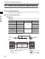
OMNUC G
SERIES
R88M-G@
(AC Servomotors)
R88D-GT@
(AC Servo Drives)
AC SERVOMOTORS/SERVO DRIVES
Trademarks and Copyrights
• Product names and system names in this manual are trademarks or registered trademarks of their
respective companies.
OMRON, 2008
All rights reserved. No part of this publication may be reproduced, stored in a retrieval system, or transmitted, in any
form, or by any means, mechanical, electronic, photocopying, recording, or otherwise, without the prior written permission of OMRON.
No patent liability is assumed with respect to the use of the information contained herein. Moreover, because OMRON is
constantly striving to improve its high-quality products, the information contained in this manual is subject to change
without notice. Every precaution has been taken in the preparation of this manual. Nevertheless, OMRON assumes no
responsibility for errors or omissions. Neither is any liability assumed for damages resulting from the use of the information contained in this publication.
Introduction
Introduction
Thank you for choosing the OMNUC G Series. This User’s Manual describes installation/wiring
methods and parameter setting procedures required for the operation of the OMNUC G Series as
well as troubleshooting and inspection methods.
Intended Readers
This manual is intended for the following personnel.
Those with knowledge of electrical systems (a qualified electrical engineer or the equivalent) as
follows:
• Personnel in charge of introducing FA equipment
• Personnel in charge of designing FA systems
• Personnel in charge of managing FA systems and facilities
NOTICE
This manual contains information necessary to ensure safe and proper use of the OMNUC G Series
and its peripheral devices. Please read this manual thoroughly and understand its contents before
using the products.
Please keep this manual handy for future reference.
Make sure this User’s Manual is delivered to the actual end user of the products.
1
Read and Understand This Manual
Read and Understand This Manual
Please read and understand this manual before using the product. Please consult your OMRON
representative if you have any questions or comments.
Warranty and Limitations of Liability
WARRANTY
OMRON's exclusive warranty is that the products are free from defects in materials and workmanship
for a period of one year (or other period if specified) from date of sale by OMRON.
OMRON MAKES NO WARRANTY OR REPRESENTATION, EXPRESS OR IMPLIED, REGARDING
NON-INFRINGEMENT, MERCHANTABILITY, OR FITNESS FOR PARTICULAR PURPOSE OF THE
PRODUCTS. ANY BUYER OR USER ACKNOWLEDGES THAT THE BUYER OR USER ALONE HAS
DETERMINED THAT THE PRODUCTS WILL SUITABLY MEET THE REQUIREMENTS OF THEIR
INTENDED USE. OMRON DISCLAIMS ALL OTHER WARRANTIES, EXPRESS OR IMPLIED.
LIMITATIONS OF LIABILITY
OMRON SHALL NOT BE RESPONSIBLE FOR SPECIAL, INDIRECT, OR CONSEQUENTIAL
DAMAGES, LOSS OF PROFITS OR COMMERCIAL LOSS IN ANY WAY CONNECTED WITH THE
PRODUCTS, WHETHER SUCH CLAIM IS BASED ON CONTRACT, WARRANTY, NEGLIGENCE, OR
STRICT LIABILITY.
In no event shall the responsibility of OMRON for any act exceed the individual price of the product on
which liability is asserted.
IN NO EVENT SHALL OMRON BE RESPONSIBLE FOR WARRANTY, REPAIR, OR OTHER CLAIMS
REGARDING THE PRODUCTS UNLESS OMRON'S ANALYSIS CONFIRMS THAT THE PRODUCTS
WERE PROPERLY HANDLED, STORED, INSTALLED, AND MAINTAINED AND NOT SUBJECT TO
CONTAMINATION, ABUSE, MISUSE, OR INAPPROPRIATE MODIFICATION OR REPAIR.
2
Read and Understand This Manual
Application Considerations
SUITABILITY FOR USE
OMRON shall not be responsible for conformity with any standards, codes, or regulations that apply to
the combination of products in the customer's application or use of the products.
At the customer's request, OMRON will provide applicable third party certification documents identifying
ratings and limitations of use that apply to the products. This information by itself is not sufficient for a
complete determination of the suitability of the products in combination with the end product, machine,
system, or other application or use.
The following are some examples of applications for which particular attention must be given. This is not
intended to be an exhaustive list of all possible uses of the products, nor is it intended to imply that the
uses listed may be suitable for the products:
• Outdoor use, uses involving potential chemical contamination or electrical interference, or conditions
or uses not described in this manual.
• Nuclear energy control systems, combustion systems, railroad systems, aviation systems, medical
equipment, amusement machines, vehicles, safety equipment, and installations subject to separate
industry or government regulations.
• Systems, machines, and equipment that could present a risk to life or property.
Please know and observe all prohibitions of use applicable to the products.
NEVER USE THE PRODUCTS FOR AN APPLICATION INVOLVING SERIOUS RISK TO LIFE OR
PROPERTY WITHOUT ENSURING THAT THE SYSTEM AS A WHOLE HAS BEEN DESIGNED TO
ADDRESS THE RISKS, AND THAT THE OMRON PRODUCTS ARE PROPERLY RATED AND
INSTALLED FOR THE INTENDED USE WITHIN THE OVERALL EQUIPMENT OR SYSTEM.
PROGRAMMABLE PRODUCTS
OMRON shall not be responsible for the user's programming of a programmable product, or any
consequence thereof.
Disclaimers
CHANGE IN SPECIFICATIONS
Product specifications and accessories may be changed at any time based on improvements and other
reasons.
It is our practice to change model numbers when published ratings or features are changed, or when
significant construction changes are made. However, some specifications of the products may be
changed without any notice. When in doubt, special model numbers may be assigned to fix or establish
key specifications for your application on your request. Please consult with your OMRON representative
at any time to confirm actual specifications of purchased products.
DIMENSIONS AND WEIGHTS
Dimensions and weights are nominal and are not to be used for manufacturing purposes, even when
tolerances are shown.
3
Read and Understand This Manual
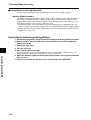
PERFORMANCE DATA
Performance data given in this manual is provided as a guide for the user in determining suitability and
does not constitute a warranty. It may represent the result of OMRON's test conditions, and the users
must correlate it to actual application requirements. Actual performance is subject to the OMRON
Warranty and Limitations of Liability.
ERRORS AND OMISSIONS
The information in this manual has been carefully checked and is believed to be accurate; however, no
responsibility is assumed for clerical, typographical, or proofreading errors, or omissions.
4
Precautions for Safe Use
Precautions for Safe Use
To ensure safe and proper use of the OMNUC G Series and its peripheral devices, read the “Precautions for
Safe Use” and the rest of the manual thoroughly to acquire sufficient knowledge of the devices, safety
information, and precautions before using the products.
Make sure this User’s Manual is delivered to the actual end users of the products.
Please keep this manual close at hand for future reference.
Explanation of Signal Words
The precautions indicated here provide important information for safety. Be sure to heed the information
provided with the precautions.
The following signal words are used to indicate and classify precautions in this manual.
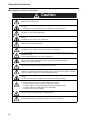
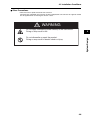
WARNING
Caution
Indicates a potentially hazardous situation which, if not
avoided, could result in death or serious injury.
Additionally, there may be severe property damage.
Indicates a potentially hazardous situation which, if not
avoided, may result in minor or moderate injury, or property
damage.
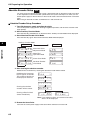
Failure to heed the precautions classified as “Caution” may also lead to serious results. Always
heed these precautions.
Safety Precautions
This manual may include illustrations of the product with protective covers or shields removed in order to show
the components of the product in detail. Make sure that these protective covers and shields are put in place as
specified before using the product.
Consult your OMRON representative when using the product after a long period of storage.
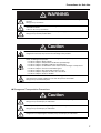
WARNING
Always connect the frame ground terminals of the Servo Drive and the Servomotor to 100 Ω
or less.
Incorrect grounding may result in electric shock.
Do not touch the inside of the Servo Drive.
Doing so may result in electric shock.
When turning OFF the main circuit power supply, turn OFF the RUN Command Input (RUN)
at the same time. Residual voltage may cause the Servomotor to continue rotating and result
in injury or equipment damage even if the main circuit power supply is turned OFF externally,
e.g., with an emergency stop.
Do not remove the front cover, terminal covers, cables, or optional items while the power is
being supplied.
Doing so may result in electric shock.
5
Precautions for Safe Use
Installation, operation, maintenance, or inspection must be performed by authorized
personnel.
Not doing so may result in electric shock or injury.
Wiring or inspection must not be performed for at least 15 minutes after turning OFF the
power supply.
Doing so may result in electric shock.
Do not damage or pull on the cables, place heavy objects on them, or subject them to
excessive stress.
Doing so may result in electric shock, stopping product operation, or burning.
Do not touch the rotating parts of the Servomotor during operation.
Doing so may result in injury.
Do not modify the product.
Doing so may result in injury or damage to the product.
Provide a stopping mechanism on the machine to ensure safety.
*The holding brake is not designed as a stopping mechanism for safety purposes.
Not doing so may result in injury.
Provide an external emergency stopping mechanism that can stop operation and shut off the
power supply immediately.
Not doing so may result in injury.
Do not come close to the machine immediately after resetting momentary power interruption
to avoid an unexpected restart.
Doing so may result in injury.
Take appropriate measures to secure safety against an unexpected restart.
Confirm safety after an earthquake has occurred.
Failure to do so may result in electric shock, injury, or fire.
Do not use external force to drive the Servomotor.
Doing so may result in fire.
6
Precautions for Safe Use
WARNING
Do not place any flammable materials near the Servomotor, Servo Drive, or Regeneration
Resistor.
Doing so may result in fire.
Mount the Servomotor, Servo Drive, and Regeneration Resistor on metal or other nonflammable materials.
Failure to do so may result in fire.
Do not frequently and repeatedly turn the main power supply ON and OFF.
Doing so may result in product failure.
Caution
Use the Servomotors and Servo Drives in a specified combination.
Using them incorrectly may result in fire or damage to the products.
Do not store or install the product in the following places. Doing so may result in fire, electric
shock, or damage to the product.
• Locations subject to direct sunlight.
• Locations subject to temperatures outside the specified range.
• Locations subject to humidity outside the specified range.
• Locations subject to condensation as the result of severe changes in temperature.
• Locations subject to corrosive or flammable gases.
• Locations subject to dust (especially iron dust) or salts.
• Locations subject to exposure to water, oil, or chemicals.
• Locations subject to shock or vibration.
Do not touch the Servo Drive radiator, Servo Drive regeneration resistor, or Servomotor
while the power is being supplied or soon after the power is turned OFF.
Doing so may result in burn injuries.
Storage and Transportation Precautions
Caution
Do not hold the product by the cables or motor shaft while transporting it.
Doing so may result in injury or malfunction.
Do not place any load exceeding the figure indicated on the product.
Doing so may result in injury or malfunction.
Use the motor eye-bolts only for transporting the Servomotor.
Using them for transporting the machinery may result in injury or malfunction.
7
Precautions for Safe Use
Installation and Wiring Precautions
Caution
Do not step on or place a heavy object on the product.
Doing so may result in injury.
Do not cover the inlet or outlet ports and prevent any foreign objects from entering the
product.
Covering them or not preventing entry of foreign objects may result in fire.
Be sure to install the product in the correct direction.
Not doing so may result in malfunction.
Provide the specified clearances between the Servo Drive and the control panel or with other
devices.
Not doing so may result in fire or malfunction.
Do not subject Servomotor shaft or Servo Drive to strong impacts.
Doing so may result in malfunction.
Be sure to wire correctly and securely.
Not doing so may result in motor runaway, injury, or malfunction.
Be sure that all the mounting screws, terminal screws, and cable connector screws are
tightened properly.
Incorrect tightening torque may result in malfunction.
Use crimp terminals for wiring.
Do not connect bare stranded wires directly to the protective ground terminal.
Doing so may result in burning.
Always use the power supply voltage specified in the User’s Manual.
An incorrect voltage may result in malfunction or burning.
Take appropriate measures to ensure that the specified power with the rated voltage and
frequency is supplied. Be particularly careful in places where the power supply is unstable.
An incorrect power supply may result in equipment damage.
Install external breakers and take other safety measures against short-circuiting in external
wiring.
Insufficient safety measures against short-circuiting may result in burning.
Take appropriate and sufficient shielding measures when installing systems in the following
locations. Failure to do so may result in damage to the product.
• Locations subject to static electricity or other forms of noise.
• Locations subject to strong electromagnetic fields and magnetic fields.
• Locations subject to possible exposure to radioactivity.
• Locations close to power supplies.
Connect an emergency stop cutoff relay in series with the brake control relay.
Failure to do so may result in injury or product failure.
Do not reverse the polarity of the battery when connecting it.
Reversing the polarity may damage the battery or cause it to explode.
8
Precautions for Safe Use
Operation and Adjustment Precautions
Caution
Confirm that no adverse effects will occur in the system before performing the test operation.
Not doing so may result in equipment damage.
Check the newly set parameters for proper operation before actually running them.
Not doing so may result in equipment damage.
Do not make any extreme adjustments or setting changes.
Doing so may result in unstable operation and injury.
Separate the Servomotor from the machine, check for proper operation, and then connect to
the machine.
Not doing so may cause injury.
When an alarm occurs, remove the cause, reset the alarm after confirming safety, and then
resume operation.
Not doing so may result in injury.
Do not use the built-in brake of the Servomotor for ordinary braking.
Doing so may result in malfunction.
Do not operate the Servomotor connected to a load that exceeds the applicable load
moment of inertia.
Doing so may result in malfunction.
Maintenance and Inspection Precautions
Caution
Resume operation only after transferring to the new Unit the contents of the data required
for operation.
Not doing so may result in equipment damage.
Do not attempt to disassemble or repair any of the products.
Any attempt to do so may result in electric shock or injury.
9
Precautions for Safe Use
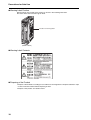
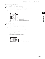
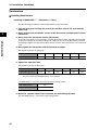
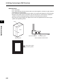
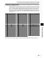
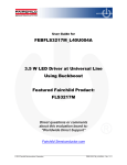
Warning Label Position
Warning labels are located on the product as shown in the following illustration.
Be sure to follow the instructions given there.
Location of warning label
(R88D-GT01H)
Warning Label Contents
Disposing of the Product
• Dispose of the batteries according to local ordinances and regulations. Wrap the batteries in tape
or other insulative material before disposing of them.
• Dispose of the product as industrial waste.
10
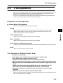
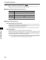
Items to Check When Unpacking
Items to Check When Unpacking
Check the following items after removing the product from the package.
• Has the correct product been delivered?
• Has the product been damaged in shipping?
Accessories Provided with Product
Safety Precautions document × 1
• No connectors or mounting screws are provided. They have to be prepared by the user.
• Should you find any problems (missing parts, damage to the Servo Drive, etc.), please contact
your local sales representative or OMRON sales office.
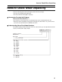
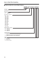
Understanding Servo Drive Model Numbers
The model number provides information such as the Servo Drive type, the applicable Servomotor
capacity, and the power supply voltage.
R88D-GT01H
OMNUC G-Series
Servo Drive
Drive Type
T: Three-mode type
Applicable Servomotor Capacity
A5: 50 W
01: 100 W
02: 200 W
04: 400 W
08: 750 W
10: 1 kW
15: 1.5 kW
20: 2 kW
30: 3 kW
50: 5 kW
75: 7.5 kW
Power Supply Voltage
L : 100 VAC
H: 200 VAC
11
Items to Check When Unpacking
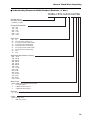
Understanding Servomotor Model Numbers
R88M-GP10030H-BOS2
G-Series
Servomotor
Motor Type
Blank: Cylinder type
P:
Flat type
Servomotor Capacity
050:
100:
200:
400:
750:
900:
1K0:
1K5:
2K0:
3K0:
4K0:
4K5:
5K0:
6K0:
7K5:
50 W
100 W
200 W
400 W
750 W
900 W
1 kW
1.5 kW
2 kW
3 kW
4 kW
4.5 kW
5 kW
6 kW
7.5 kW
Rated Rotation Speed
10:
15:
20:
30:
1,000 r/min
1,500 r/min
2,000 r/min
3,000 r/min
Applied Voltage
H:
L:
T:
S:
200 VAC with incremental encoder specifications
100 VAC with incremental encoder specifications
200 VAC with absolute encoder specifications
100 VAC with absolute encoder specifications
Option
Blank: Straight shaft
B: With brake
O: With oil seal
S2: With key and tap
12
Items to Check When Unpacking
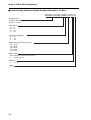
Understanding Decelerator Model Numbers (Backlash = 3' Max.)
R88G-HPG14A05100PBJ
Decelerator for
G-Series Servomotors
Backlash = 3’ Max.
Flange Size Number
11B
14A
20A
32A
50A
65A
:@40
:@60
:@90
:@120
:@170
:@230
Gear Ratio
05
09
11
12
20
21
25
33
45
:1/5
:1/9 (only frame number 11A)
:1/11 (except frame number 65A)
:1/12 (only frame number 65A)
:1/20 (only frame number 65A)
:1/21 (except frame number 65A)
:1/25 (only frame number 65A)
:1/33
:1/45
Applicable Servomotor Capacity
050
100
200
400
750
900
1K0
1K5
2K0
3K0
4K0
4K5
5K0
6K0
7K5
: 50 W
:100 W
:200 W
:400 W
:750 W
:900 W
:1 kW
:1.5 kW
:2 kW
:3 kW
:4 kW
:4.5 kW
:5 kW
:6 kW
:7.5 kW
Motor Type
Blank :3,000-r/min cylindrical Servomotors
P
:flat Servomotors
S
:2,000-r/min Servomotors
T
:1,000-r/min Servomotors
Backlash
B
:3’ max.
Option
Blank :Straight shaft
J
:With key and tap
13
Items to Check When Unpacking
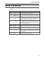
Understanding Decelerator Model Numbers (Backlash = 15' Max.)
R88G-VRSF09B100PCJ
Decelerator for
G-Series Servomotors
Backlash = 15’ Max.
Gear Ratio
05
09
15
25
:1/5
:1/9
:1/15
:1/25
Flange Size Number
B
C
D
:@52
:@78
:@98
Applicable Servomotor Capacity
050
100
200
400
750
: 50 W
:100 W
:200 W
:400 W
:750 W
Motor Type
Blank :3,000-r/min cylindrical Servomotors
P
:flat Servomotors
Backlash
C
:15’ max.
Option
J
14
:With key
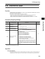
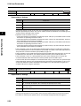
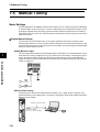
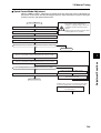
About This Manual
About This Manual
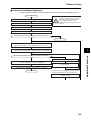
This manual consists of the following chapters. Refer to this table and chose the required chapters
of the manual.
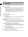
Overview
Chapter 1
Features and System
Configuration
Describes the features and names of parts of the product as well
as the EC Directives and the UL standards.
Chapter 2
Standard Models and
Dimensions
Provides the model numbers, external and mounting hole dimensions for Servo Drives, Servomotors, Decelerators, and peripheral
devices.
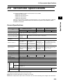
Specifications
Provides the general specifications, characteristics, connector
specifications, and I/O circuit specifications for Servo Drives, and
the general specifications and characteristics for Servomotors, as
well as specifications for accessories such as encoders.
Chapter 4
System Design
Describes the installation conditions for Servo Drives, Servomotors, and Decelerators, EMC conforming wiring methods, calculations of regenerative energy, and performance information on the
External Regeneration Resistor.
Chapter 5
Operating Functions
Describes the control functions, parameter settings, and operation.
Chapter 6
Operation
Describes operating procedures and operating methods for each
mode.
Chapter 7
Adjustment Functions
Describes gain adjustment functions, setting methods, and precautions.
Chapter 8
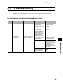
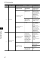
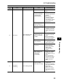
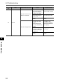
Troubleshooting
Describes items to check for troubleshooting, error diagnoses using alarm LED displays and the countermeasures, error diagnoses
based on the operation status and the countermeasures, and periodic maintenance.
Chapter 9
Appendix
Provides examples of connections with OMRON PLCs and Position Controllers, and the parameter tables.
Chapter 3
15
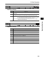
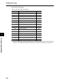
Table of Contents
Introduction ...................................................................................... 1
Read and Understand This Manual ................................................. 2
Precautions for Safe Use................................................................. 5
Items to Check When Unpacking .................................................... 11
About This Manual........................................................................... 15
Chapter 1 Features and System Configuration
1-1
1-2
1-3
1-4
1-5
Overview........................................................................................... 1-1
System Configuration ....................................................................... 1-2
Names of Parts and Functions ......................................................... 1-3
System Block Diagrams ................................................................... 1-5
Applicable Standards........................................................................ 1-10
Chapter 2 Standard Models and Dimensions
2-1
2-2
Standard Models .............................................................................. 2-1
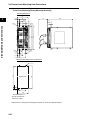
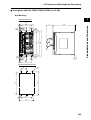
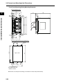
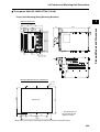
External and Mounting Hole Dimensions ......................................... 2-25
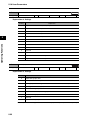
Chapter 3 Specifications
3-1
3-2
3-3
3-4
3-5
3-6
3-7
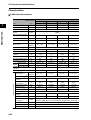
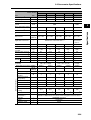
3-8
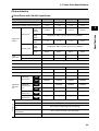
Servo Drive Specifications................................................................ 3-1
Servomotor Specifications................................................................ 3-32
Decelerator Specifications................................................................ 3-47
Cable and Connector Specifications ................................................ 3-57
Servo Relay Units and Cable Specifications .................................... 3-99
Parameter Unit Specifications .......................................................... 3-129
External Regeneration Resistor Specifications ................................ 3-130
Reactor Specifications...................................................................... 3-131
Chapter 4 System Design
4-1
4-2
4-3
4-4
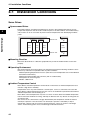
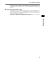
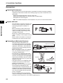
Installation Conditions ...................................................................... 4-1
Wiring ............................................................................................... 4-11
Wiring Conforming to EMC Directives .............................................. 4-27
Regenerative Energy Absorption...................................................... 4-45
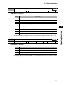
Chapter 5 Operating Functions
5-1
5-2
5-3
5-4
5-5
5-6
5-7
5-8
5-9
16
Position Control ................................................................................ 5-1
Speed Control................................................................................... 5-3
Internally Set Speed Control............................................................. 5-5
Torque Control.................................................................................. 5-8
Switching the Control Mode.............................................................. 5-11
Forward and Reverse Drive Prohibit ................................................ 5-14
Encoder Dividing .............................................................................. 5-15
Electronic Gear................................................................................. 5-16
Overrun Limit .................................................................................... 5-18
Table of Contents
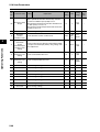
5-10
5-11
5-12
5-13
5-14
5-15
5-16
Brake Interlock ................................................................................. 5-20
Gain Switching ................................................................................. 5-24
Torque Limit ..................................................................................... 5-25
Soft Start .......................................................................................... 5-27
Position Command Filter .................................................................. 5-28
Speed Limit ...................................................................................... 5-29
User Parameters .............................................................................. 5-30
Chapter 6 Operation
6-1
6-2
6-3
6-4
6-5
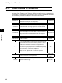
Operational Procedure ..................................................................... 6-1
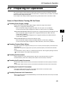
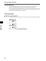
Preparing for Operation.................................................................... 6-2
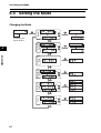
Using the Parameter Unit ................................................................. 6-6
Setting the Mode .............................................................................. 6-7
Trial Operation ................................................................................. 6-28
Chapter 7 Adjustment Functions
7-1
7-2
7-3
7-4
7-5
Gain Adjustment............................................................................... 7-1
Realtime Autotuning ......................................................................... 7-4
Normal Mode Autotuning ................................................................. 7-14
Disabling the Automatic Gain Adjustment Function ......................... 7-19
Manual Tuning ................................................................................. 7-21
Chapter 8 Troubleshooting
8-1
8-2
8-3
8-4
8-5
Error Processing .............................................................................. 8-1
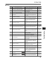
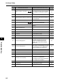
Alarm Table ...................................................................................... 8-3
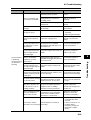
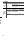
Troubleshooting ............................................................................... 8-6
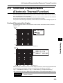
Overload Characteristics (Electronic Thermal Function).................. 8-20
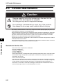
Periodic Maintenance....................................................................... 8-21
Chapter 9 Appendix
9-1
9-2
Connection Examples ...................................................................... 9-1
Parameter Tables............................................................................. 9-11
Revision History...................................................................................... R-1
17
Chapter 1
Features and System Configuration
1-1 Overview ............................................................ 1-1
Overview of the G Series ......................................................1-1
Features of the G Series .......................................................1-1
1-2 System Configuration......................................... 1-2
1-3 Names of Parts and Functions ........................... 1-3
Servo Drive Part Names .......................................................1-3
Servo Drive Functions...........................................................1-4
Forward and Reverse Motor Rotation ...................................1-4
1-4 System Block Diagrams ..................................... 1-5
1-5 Applicable Standards ......................................... 1-10
EC Directives ........................................................................1-10
UL and CSA Standards.........................................................1-10
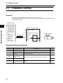
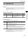
1-1 Overview
Features and System Configuration
1
1-1 Overview
Overview of the G Series
The OMNUC G Series has been developed for a wide range of applications with position control,
speed control, and torque control. The Series offers a wide variety of Servomotor capacities,
ranging from 50 W to 7.5 kW. Servomotors with 2,500-pulse incremental encoders and highresolution 17-bit absolute/incremental encoders are available as standard models.
The OMNUC G Series features realtime autotuning and adaptive filter functions that automatically
perform complicated gain adjustments. A notch filter can also be automatically set to suppress
machine vibration by reducing mechanical resonance during operation. The damping control
function of the OMNUC G Series realizes stable stopping performance in a mechanism which
vibrates because of the low rigidity of the load.
Features of the G Series
The OMNUC G Series has the following features.
High-speed Response
The G-Series AC Servomotors and Servo Drives have achieved high-speed response capabilities
exceeding OMRON’s W-Series models, with a high-response frequency of 1 kHz (compared to
400 Hz for the W Series).
Suppressing Vibration of Low-rigidity Mechanisms during Acceleration/
Deceleration
The damping control function suppresses vibration of low-rigidity mechanisms or devices whose
ends tend to vibrate. Two vibration filters are provided to enable switching the vibration frequency
automatically according to the direction of rotation and also via an external signal. In addition, the
settings can be made easily merely by just setting the vibration frequency and filter values, and you
are assured of stable operation even if the settings are inappropriate.
High-speed Positioning via Resonance Suppression Control
The realtime autotuning function automatically estimates the load inertia of the machine in realtime
and sets the optimal gain. The adaptive filter automatically suppresses vibration caused by
resonance. Also, two independent notch filters make it possible to reduce vibration of a mechanism
with multiple resonance frequencies.
Command Control Mode Switching
Operation can be performed by switching between two of the following control modes: Position
control, speed control (including internal speed) and torque control. Therefore, a variety of
applications can be supported by one Servo Drive.
Simplified Speed Control with Internal Speed Settings
Eight internal speed settings allow you to change the speed easily by using external signals.
1-1
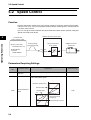
1-2 System Configuration
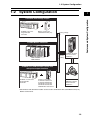
1-2 System Configuration
1
SYSMAC CS-series
Programmable
Controller
Motion Control Unit
CS1W-MC221/421(-V1)
Features and System Configuration
Controller with Voltage Output
Analog voltage
Flexible Motion Controller
FQM1-MMA22
FQM1-MMP22
Pulse
string
OMNUC G-Series
AC Servo Drive
R88D-G@
SYSMAC PLC and Position Control Unit
with pulse output functions
SYSMAC CJ/CS-series
Programmable
Controller
Position Control Unit
CJ1W-NC113/213/413
CJ1W-NC133/233/433
CS1W-NC113/213/413
CS1W-NC133/233/433
C200HW-NC113/213/413
INC
ABS
OMNUC G-Series
AC Servomotor
R88M-G@
Servomotors with absolute encoders can be used in combination with CS1W-MC221/421(-V1)
Motion Control Units.
1-2
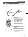
1-3 Names of Parts and Functions
Features and System Configuration
1
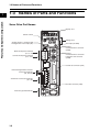
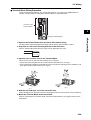
1-3 Names of Parts and Functions
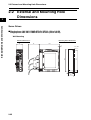
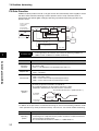
Servo Drive Part Names
Display area
Unit No. switch
Settings area
Analog monitor 1 check pin (IM)
Analog monitor 2 check pin (SP)
Main-circuit power terminals
(L1, L2, L3)
Control-circuit power terminals
(L1C, L2C)
Check pin (G: GND)
RS-485
Communications connector
(CN3A)
RS-232
Communications connector/
Parameter Unit connector
(CN3B)
Control I/O connector (CN1)
External Regeneration Resistor
connection terminals
(B1, B2, B3)
Servomotor connection terminals
(U, V, W)
Encoder connector (CN2)
Protective ground terminals
1-3
1-3 Names of Parts and Functions
Servo Drive Functions
1
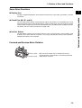
Display Area
Check Pins (IM, SP, and G)
The actual Servomotor speed, command speed, torque, and number of accumulated pulses can be
measured based on the analog voltage level by using an oscilloscope. The type of signal to output
and the output voltage level are set in the SP Selection (Pn07) and IM Selection (Pn08) parameters.
For details, refer to 5-16 User Parameters on page 5-30.
Unit No. Switch
The Servo Drive number in serial communications is set to a value from 0 to F. This number is used
to identify which Servo Drive the computer is accessing in RS-232/485 communications between
multiple Servo Drives and a computer.
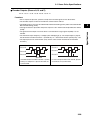
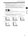
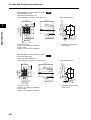
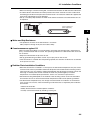
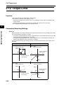
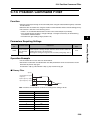
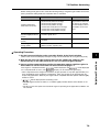
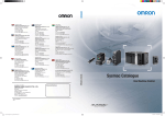
Forward and Reverse Motor Rotation
Reverse (CW)
Forward (CCW)
When the motor output shaft is viewed from the end,
counterclockwise (CCW) rotation is forward and clockwise
(CW) rotation is reverse.
1-4
Features and System Configuration
A 6-digit 7-segment LED display shows the Servo Drive status, alarm codes, parameters, and other
information.
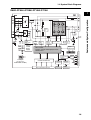
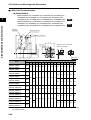
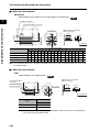
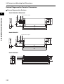
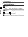
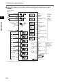
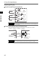
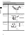
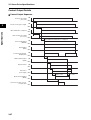
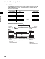
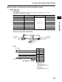
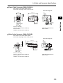
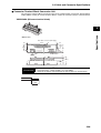
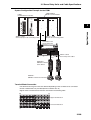
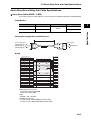
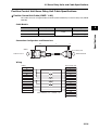
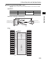
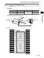
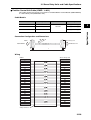
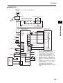
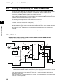
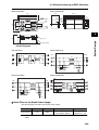
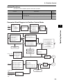
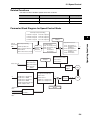
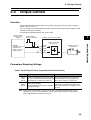
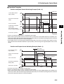
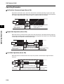
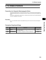
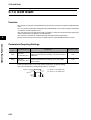
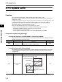
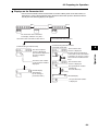
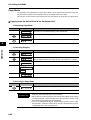
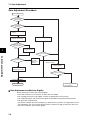
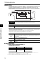
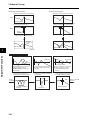
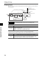
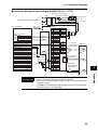
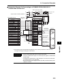
1-4 System Block Diagrams
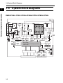
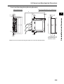
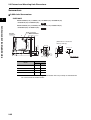
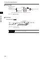
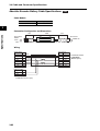
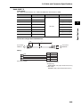
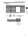
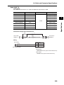
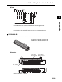
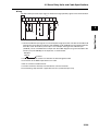
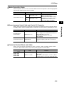
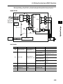
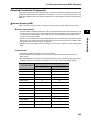
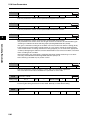
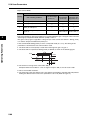
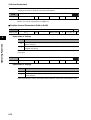
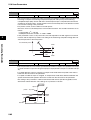
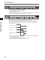
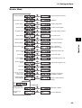
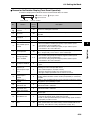
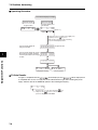
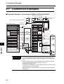
1-4 System Block Diagrams
R88D-GTA5L/-GT01L/-GT02L/-GTA5H/-GT01H/-GT02H/-GT04H
Voltage
detection
SW power
supply
Main circuit
control
E5V
Internal
control
power
supply
Relay
drive
Regenerative
control
Overcurrent
detection
Current
detection
Gate drive
Display/
setting circuits
MPU & ASIC
Position, speed, and torque processor,
PWM control
Encoder
communications
interface
+E5V
Control I/O interface
CN1 control I/O connector
1-5
RS485
RS-232
interface
RS-485
interface
CN3A
connector
CN3B
connector
CN2 encoder signal connector
Features and System Configuration
1
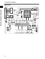
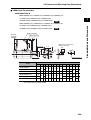
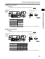
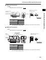
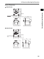
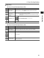
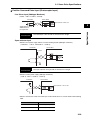
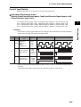
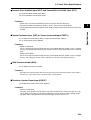
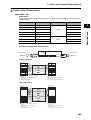
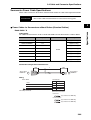
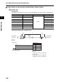
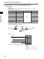
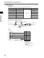
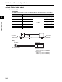
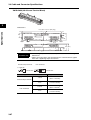
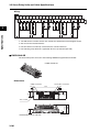
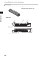
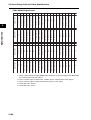
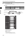
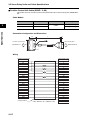
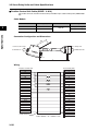
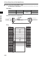
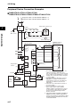
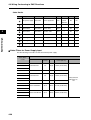
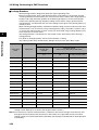
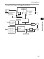
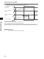
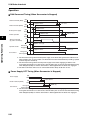
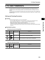
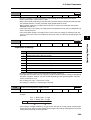
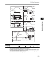
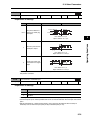
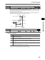
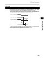
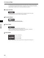
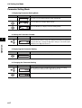
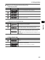
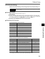
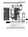
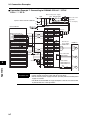
1-4 System Block Diagrams
R88D-GT04L/-GT08H/-GT10H/-GT15H
1
Voltage
detection
E5V
Internal
control
power
supply
Relay
drive
Regenerative
control
Overcurrent
detection
Current
detection
Gate drive
Display/
setting circuits
MPU & ASIC
Position, speed, and torque processor,
PWM control
Encoder
communications
interface
Cooling fan
(except for the
R88D-GT04L/-GT08H)
+E5V
Control I/O interface
CN1 control I/O connector
RS485
RS-232
interface
RS-485
interface
CN3A
connector
CN3B
connector
CN2 encoder signal connector
SW power
supply
Main circuit
control
1-6
Features and System Configuration
Internal regeneration resistor
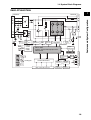
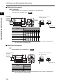
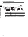
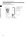
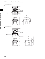
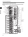
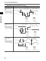
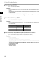
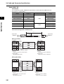
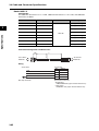
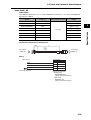
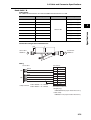
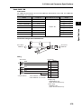
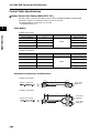
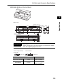
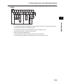
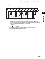
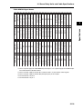
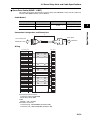
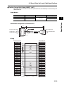
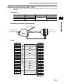
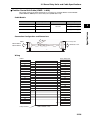
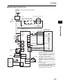
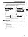
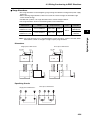
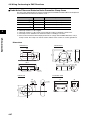
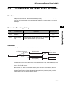
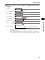
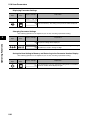
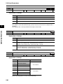
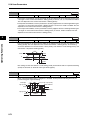
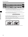
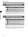
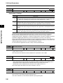
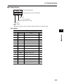
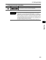
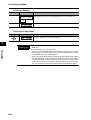
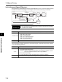
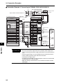
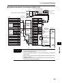
1-4 System Block Diagrams
R88D-GT20H
Terminals
Terminals
Internal regeneration resistor
SW power
supply
Main circuit
control
E5V
Internal
control
power
supply
Relay
drive
Regenerative
control
Voltage
detection
Current
detection
Gate drive
Display/
setting circuits
MPU & ASIC
Position, speed, and torque processor,
PWM control
Encoder
communications
interface
RS485
+E5V
Control I/O interface
Cooling fan
CN1 control I/O connector
1-7
RS-232
interface
RS-485
interface
CN3A
connector
CN3B
connector
CN2 encoder signal connector
Features and System Configuration
1
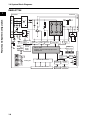
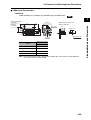
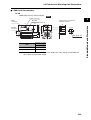
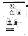
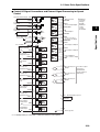
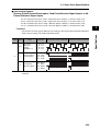
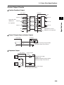
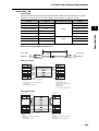
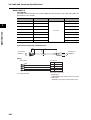
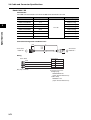
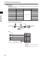
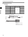
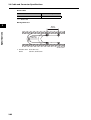
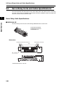
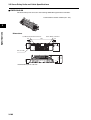
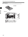
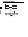
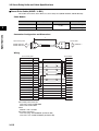
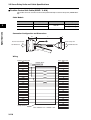
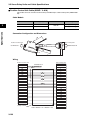
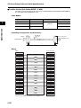
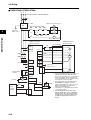
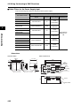
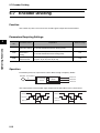
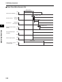
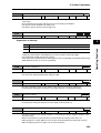
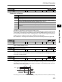
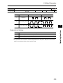
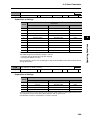
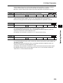
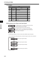
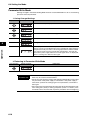
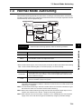
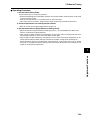
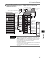
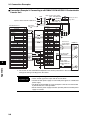
1-4 System Block Diagrams
R88D-GT30H/GT50H
1
Terminals
Internal regeneration resistor
E5V
Internal
control
power
supply
Relay
Gate drive
Regenerative
control
Voltage
detection
Current
detection
Gate drive
Display/
setting circuits
MPU & ASIC
Position, speed, and torque processor,
PWM control
Encoder
communications
interface
Cooling fan
+E5V
Control I/O interface
CN1 control I/O connector
RS485
RS-232
interface
RS-485
interface
CN3A
connector
CN3B
connector
CN2 encoder signal connector
SW power
supply
Main circuit
control
1-8
Features and System Configuration
Terminals
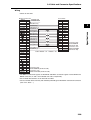
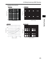
1-4 System Block Diagrams
R88D-GT75H
Features and System Configuration
Terminals
Terminals
SW power
supply
Main circuit
control
E5V
Internal
control
power
supply
Relay
Gate drive
Regenerative
control
Voltage
detection
Current
detection
Gate drive
Display/
setting circuits
MPU & ASIC
Position, speed, and torque processor,
PWM control
Encoder
communications
interface
Cooling fan
1-9
+E5V
Control I/O interface
CN1 control I/O connector
RS485
RS-232
interface
RS-485
interface
CN3A
connector
CN3B
connector
CN2 encoder signal connector
1
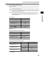
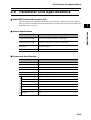
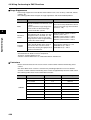
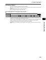
1-5 Applicable Standards
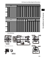
1-5 Applicable Standards
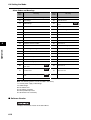
EC Directives
EC Directive
Product
Applicable standards
Comments
Safety requirements for electrical equipment for
EN 50178
measurement, control, or laboratory use
IEC 60034-1/-5
Rotating electrical machines
Limits of radio disturbance and measurement
EN 55011 Class A Group1 methods for industrial, scientific, and medical
radio-frequency equipment
Electromagnetic compatibility (EMC) Immunity
EN 61000-6-2
standard for industrial environments
IEC 61000-4-2
Electrostatic discharge immunity testing
IEC 61000-4-3
Radio frequency radiation field immunity testing
IEC 61000-4-4
Electrical fast transient burst immunity testing
IEC 61000-4-5
Lightning surge immunity testing
IEC 61000-4-6
High-frequency conduction immunity testing
IEC 61000-4-11
Momentary power interruption immunity testing
AC Servo Drive
Low Voltage
Directive
AC Servomotor
EMC Directive
AC Servo Drive and
AC Servomotor
Note To conform to EMC Directives, the Servomotor and Servo Drive must be installed under the conditions
described in Wiring Conforming to EMC Directives on page 4-27.
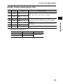
UL and CSA Standards
Standard
UL
standard
CSA
standard
Product
AC Servo Drive
AC Servomotor *1
Applicable standards
File number
UL 508C
E179149
UL1004
E179189
Comments
Power conversion equipment
Electric motor
AC Servomotors*1
CSA22.2 No.100
Motor and generator
E179189
*1 UL approval is pending for Servomotor capacities of 6 to 7.5 kW.
1-10
Features and System Configuration
1
Chapter 2
Standard Models and Dimensions
2-1 Standard Models ................................................ 2-1
Servo Drives .........................................................................2-1
Servomotors..........................................................................2-2
Servo Drive-Servomotor Combinations ................................2-5
Decelerators..........................................................................2-7
Accessories and Cables .......................................................2-14
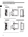
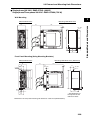
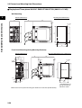
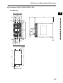
2-2 External and Mounting Hole Dimensions ........... 2-25
Servo Drives .........................................................................2-25
Servomotors..........................................................................2-35
Parameter Unit Dimensions ..................................................2-45
Servomotor and Decelerator Combinations ..........................2-46
Decelerator Dimensions........................................................2-49
External Regeneration Resistor Dimensions ........................2-63
Reactor Dimensions..............................................................2-64
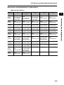
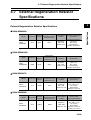
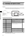
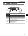
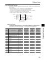
2-1 Standard Models
2-1 Standard Models
2
Standard Models and Dimensions
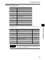
Servo Drives
Specifications
Model
50 W
R88D-GTA5L
100 W
R88D-GT01L
200 W
R88D-GT02L
400 W
R88D-GT04L
Single-phase 100 VAC
50 W
R88D-GT01H
100 W
Single-phase 200 VAC
Single-phase/three-phase 200 VAC
200 W
R88D-GT02H
400 W
R88D-GT04H
750 W
R88D-GT08H
1 kW
R88D-GT10H
900 W
1 kW
R88D-GT15H
1.5 kW
2 kW
R88D-GT20H
2 kW
R88D-GT30H
3 kW
3 kW
Three-phase 200 VAC
4 kW
R88D-GT50H
4.5 kW
5 kW
6 kW
R88D-GT75H
7.5 kW
2-1
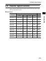
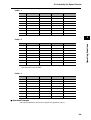
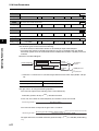
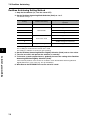
2-1 Standard Models
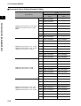
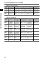
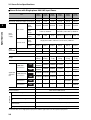
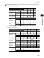
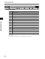
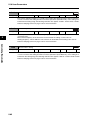
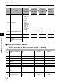
Servomotors
3,000-r/min Servomotors
2
Model
Straight shaft without
key
100 V
Without
brake
With
brake
Straight shaft without
key
Straight shaft with key
and tap
50 W R88M-G05030H
R88M-G05030H-S2
R88M-G05030T
R88M-G05030T-S2
100 W R88M-G10030L
R88M-G10030L-S2
R88M-G10030S
R88M-G10030S-S2
200 W R88M-G20030L
R88M-G20030L-S2
R88M-G20030S
R88M-G20030S-S2
400 W R88M-G40030L
R88M-G40030L-S2
R88M-G40030S
R88M-G40030S-S2
50 W R88M-G05030H
R88M-G05300H-S2
R88M-G05030T
R88M-G05030T-S2
100 W R88M-G10030H
R88M-G10030H-S2
R88M-G10030T
R88M-G10030T-S2
200 W R88M-G20030H
R88M-G20030H-S2
R88M-G20030T
R88M-G20030T-S2
400 W R88M-G40030H
R88M-G40030H-S2
R88M-G40030T
R88M-G40030T-S2
750 W R88M-G75030H
R88M-G75030H-S2
R88M-G75030T
R88M-G75030T-S2
200 V 1 kW
100 V
Straight shaft with key
and tap
With absolute encoder
---
---
R88M-G1K030T
R88M-G1K030T-S2
1.5 kW
---
---
R88M-G1K530T
R88M-G1K530T-S2
2 kW
---
---
R88M-G2K030T
R88M-G2K030T-S2
3 kW
---
---
R88M-G3K030T
R88M-G3K030T-S2
4 kW
---
---
R88M-G4K030T
R88M-G4K030T-S2
5 kW
---
---
R88M-G5K030T
R88M-G5K030T-S2
50 W R88M-G05030H-B
R88M-G05030H-BS2
R88M-G05030T-B
R88M-G05030T-BS2
100 W R88M-G10030L-B
R88M-G10030L-BS2
R88M-G10030S-B
R88M-G10030S-BS2
200 W R88M-G20030L-B
R88M-G20030L-BS2
R88M-G20030S-B
R88M-G20030S-BS2
400 W R88M-G40030L-B
R88M-G40030L-BS2
R88M-G40030S-B
R88M-G40030S-BS2
50 W R88M-G05030H-B
R88M-G05030H-BS2
R88M-G05030T-B
R88M-G05030T-BS2
100 W R88M-G10030H-B
R88M-G10030H-BS2
R88M-G10030T-B
R88M-G10030T-BS2
200 W R88M-G20030H-B
R88M-G20030H-BS2
R88M-G20030T-B
R88M-G20030T-BS2
400 W R88M-G40030H-B
R88M-G40030H-BS2
R88M-G40030T-B
R88M-G40030T-BS2
750 W R88M-G75030H-B
R88M-G75030H-BS2
R88M-G75030T-B
R88M-G75030T-BS2
200 V 1 kW
---
---
R88M-G1K030T-B
R88M-G1K030T-BS2
1.5 kW
---
---
R88M-G1K530T-B
R88M-G1K530T-BS2
2 kW
---
---
R88M-G2K030T-B
R88M-G2K030T-BS2
3 kW
---
---
R88M-G3K030T-B
R88M-G3K030T-BS2
4 kW
---
---
R88M-G4K030T-B
R88M-G4K030T-BS2
5 kW
---
---
R88M-G5K030T-B
R88M-G5K030T-BS2
Note Models with oil seals are also available.
2-2
Standard Models and Dimensions
Specifications
With incremental encoder
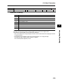
2-1 Standard Models
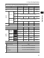
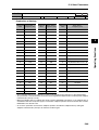
3,000-r/min Flat Servomotors
Model
Specifications
2
Standard Models and Dimensions
With incremental encoder
Straight shaft without
key
Without
brake
With
brake
Straight shaft with key
and tap
With absolute encoder
Straight shaft without
key
100 W R88M-GP10030L
R88M-GP10030L-S2
R88M-GP10030S
R88M-GP10030S-S2
100 V 200 W R88M-GP20030L
R88M-GP20030L-S2
R88M-GP20030S
R88M-GP20030S-S2
400 W R88M-GP40030L
R88M-GP40030L-S2
R88M-GP40030S
R88M-GP40030S-S2
100 W R88M-GP10030H
R88M-GP10030H-S2
R88M-GP10030T
R88M-GP10030T-S2
200 V 200 W R88M-GP20030H
R88M-GP20030H-S2
R88M-GP20030T
R88M-GP20030T-S2
400 W R88M-GP40030H
R88M-GP40030H-S2
R88M-GP40030T
R88M-GP40030T-S2
100 W R88M-GP10030L-B
R88M-GP10030L-BS2 R88M-GP10030S-B
R88M-GP10030S-BS2
100 V 200 W R88M-GP20030L-B
R88M-GP20030L-BS2 R88M-GP20030S-B
R88M-GP20030S-BS2
400 W R88M-GP40030L-B
R88M-GP40030L-BS2 R88M-GP40030S-B
R88M-GP40030S-BS2
100 W R88M-GP10030H-B
R88M-GP10030H-BS2 R88M-GP10030T-B
R88M-GP10030T-BS2
200 V 200 W R88M-GP20030H-B
R88M-GP20030H-BS2 R88M-GP20030T-B
R88M-GP20030T-BS2
400 W R88M-GP40030H-B
R88M-GP40030H-BS2 R88M-GP40030T-B
R88M-GP40030T-BS2
Note Models with oil seals are also available.
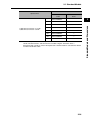
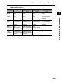
2,000-r/min Servomotors
Model
Specifications
With absolute encoder
Straight shaft without Straight shaft with key and
key
tap
1 kW R88M-G1K020T
R88M-G1K020T-S2
1.5 kW R88M-G1K520T
R88M-G1K520T-S2
2 kW R88M-G2K020T
Without 200 V 3 kW R88M-G3K020T
brake
4 kW R88M-G4K020T
R88M-G2K020T-S2
5 kW R88M-G5K020T
R88M-G5K020T-S2
7.5 kW R88M-G7K515T
R88M-G7K515T-S2
R88M-G3K020T-S2
R88M-G4K020T-S2
1 kW R88M-G1K020T-B
R88M-G1K020T-BS2
1.5 kW R88M-G1K520T-B
R88M-G1K520T-BS2
2 kW R88M-G2K020T-B
With
200 V 3 kW R88M-G3K020T-B
brake
4 kW R88M-G4K020T-B
R88M-G2K020T-BS2
5 kW R88M-G5K020T-B
R88M-G5K020T-BS2
7.5 kW R88M-G7K515T-B
R88M-G7K515T-BS2
R88M-G3K020T-BS2
R88M-G4K020T-BS2
Note 1. Models with oil seals are also available.
Note 2. The rated rotation speed for 7.5-kW Servomotors is 1,500 r/min.
2-3
Straight shaft with key
and tap
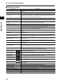
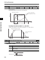
2-1 Standard Models
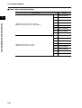
1,000-r/min Servomotors
Straight shaft with key
and tap
Straight shaft without key
900 W R88M-G90010T
R88M-G90010T-S2
2 kW R88M-G2K010T
Without 200 V 3 kW R88M-G3K010T
brake
4.5 kW R88M-G4K510T
R88M-G2K010T-S2
6 kW R88M-G6K010T
R88M-G6K010T-S2
900 W R88M-G90010T-B
R88M-G90010T-BS2
2 kW R88M-G2K010T-B
With
200 V 3 kW R88M-G3K010T-B
brake
4.5 kW R88M-G4K510T-B
R88M-G2K010T-BS2
6 kW R88M-G6K010T-B
R88M-G6K010T-BS2
2
R88M-G3K010T-S2
Standard Models and Dimensions
Specifications
Model
With absolute encoder
R88M-G4K510T-S2
R88M-G3K010T-BS2
R88M-G4K510T-BS2
Note Models with oil seals are also available.
2-4
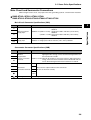
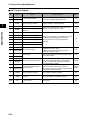
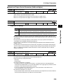
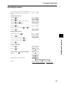
2-1 Standard Models
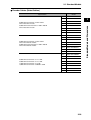
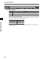
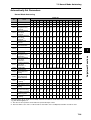
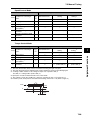
Servo Drive-Servomotor Combinations
The tables in this section show the possible combinations of OMNUC G-Series Servo Drives and
Servomotors. The Servomotors and Servo Drives can only be used in the listed combinations. The
box (-@) at the end of the model number is for options, such as the shaft type, brake and
Decelerators.
2
Standard Models and Dimensions
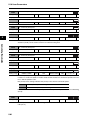
3,000-r/min Servomotors and Servo Drives
Voltage
100 V
Singlephase 200 V
Singlephase/threephase 200 V
Three-phase
200 V
Servomotor
Rated output
With incremental encoder
With absolute encoder
Servo Drive
50 W
R88M-G05030H-@
R88M-G05030T-@
R88D-GTA5L
100 W
R88M-G10030L-@
R88M-G10030S-@
R88D-GT01L
200 W
R88M-G20030L-@
R88M-G20030S-@
R88D-GT02L
400 W
R88M-G40030L-@
R88M-G40030S-@
R88D-GT04L
50 W
R88M-G05030H-@
R88M-G05030T-@
R88D-GT01H
100 W
R88M-G10030H-@
R88M-G10030T-@
R88D-GT01H
200 W
R88M-G20030H-@
R88M-G20030T-@
R88D-GT02H
400 W
R88M-G40030H-@
R88M-G40030T-@
R88D-GT04H
750 W
R88M-G75030H-@
R88M-G75030T-@
R88D-GT08H
1 kW
---
R88M-G1K030T-@
R88D-GT15H
1.5 kW
---
R88M-G1K530T-@
R88D-GT15H
2 kW
---
R88M-G2K030T-@
R88D-GT20H
3 kW
---
R88M-G3K030T-@
R88D-GT30H
4 kW
---
R88M-G4K030T-@
R88D-GT50H
5 kW
---
R88M-G5K030T-@
R88D-GT50H
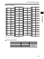
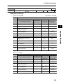
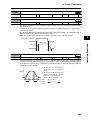
3,000-r/min Flat Servomotors and Servo Drives
Voltage
100 V
Singlephase 200 V
2-5
Servomotor
Rated output
With incremental encoder
With absolute encoder
Servo Drive
100 W
R88M-GP10030L-@
R88M-GP10030S-@
R88D-GT01L
200 W
R88M-GP20030L-@
R88M-GP20030S-@
R88D-GT02L
400 W
R88M-GP40030L-@
R88M-GP40030S-@
R88D-GT04L
100 W
R88M-GP10030H-@
R88M-GP10030T-@
R88D-GT01H
200 W
R88M-GP20030H-@
R88M-GP20030T-@
R88D-GT02H
400 W
R88M-GP40030H-@
R88M-GP40030T-@
R88D-GT04H
2-1 Standard Models
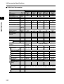
2,000-r/min Servomotors and Servo Drives
Single-phase/
three-phase 200 V
Three-phase
200 V
Servomotor
Rated output
With absolute encoder
Servo Drive
1 kW
R88M-G1K020T-@
R88D-GT10H
1.5 kW
R88M-G1K520T-@
R88D-GT15H
2 kW
R88M-G2K020T-@
R88D-GT20H
3 kW
R88M-G3K020T-@
R88D-GT30H
4 kW
R88M-G4K020T-@
R88D-GT50H
5 kW
R88M-G5K020T-@
R88D-GT50H
7.5 kW
R88M-G7K515T-@
R88D-GT75H
2
Standard Models and Dimensions
Voltage
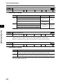
1,000-r/min Servomotors and Servo Drives
Voltage
Single-phase/
three-phase 200 V
Three-phase 200 V
Servomotor
Rated output
With absolute encoder
Servo Drive
900 W
R88M-G90010T-@
R88D-GT15H
2 kW
R88M-G2K010T-@
R88D-GT30H
3 kW
R88M-G3K010T-@
R88D-GT50H
4.5 kW
R88M-G4K510T-@
R88D-GT50H
6 kW
R88M-G6K010T-@
R88D-GT75H
2-6
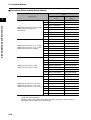
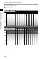
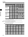
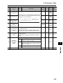
2-1 Standard Models
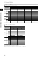
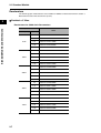
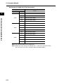
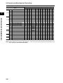
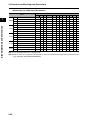
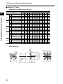
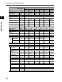
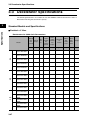
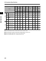
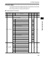
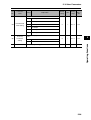
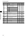
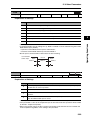
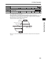
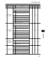
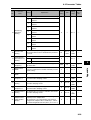
Decelerators
The following types of Decelerators are available for OMNUC G-Series Servomotors. Select a
Decelerator based on the Servomotor capacity.
2
Backlash = 3’ Max.
Decelerators for 3,000-r/min Servomotors
Standard Models and Dimensions
Specifications
Model
Motor capacity
50 W
100 W
200 W
400 W
750 W
2-7
Gear ratio
1/5
R88G-HPG11B05100B@
1/9
R88G-HPG11B09050B@
1/21
R88G-HPG14A21100B@
1/33
R88G-HPG14A33050B@
1/45
R88G-HPG14A45050B@
1/5
R88G-HPG11B05100B@
1/11
R88G-HPG14A11100B@
1/21
R88G-HPG14A21100B@
1/33
R88G-HPG20A33100B@
1/45
R88G-HPG20A45100B@
1/5
R88G-HPG14A05200B@
1/11
R88G-HPG14A11200B@
1/21
R88G-HPG20A21200B@
1/33
R88G-HPG20A33200B@
1/45
R88G-HPG20A45200B@
1/5
R88G-HPG14A05400B@
1/11
R88G-HPG20A11400B@
1/21
R88G-HPG20A21400B@
1/33
R88G-HPG32A33400B@
1/45
R88G-HPG32A45400B@
1/5
R88G-HPG20A05750B@
1/11
R88G-HPG20A11750B@
1/21
R88G-HPG32A21750B@
1/33
R88G-HPG32A33750B@
1/45
R88G-HPG32A45750B@
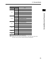
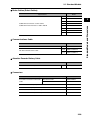
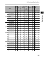
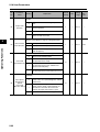
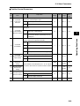
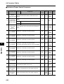
2-1 Standard Models
Specifications
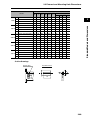
1 kW
1.5 kW
2 kW
3 kW
4 kW
5 kW
Gear ratio
Model
1/5
R88G-HPG32A051K0B@
1/11
R88G-HPG32A111K0B@
1/21
R88G-HPG32A211K0B@
1/33
R88G-HPG32A331K0B@
1/45
R88G-HPG50A451K0B@
1/5
R88G-HPG32A052K0B@
1/11
R88G-HPG32A112K0B@
1/21
R88G-HPG32A211K5B@
1/33
R88G-HPG50A332K0B@
1/45
R88G-HPG50A451K5B@
1/5
R88G-HPG32A052K0B@
1/11
R88G-HPG32A112K0B@
1/21
R88G-HPG50A212K0B@
1/33
R88G-HPG50A332K0B@
1/5
R88G-HPG32A053K0B@
1/11
R88G-HPG50A113K0B@
1/21
R88G-HPG50A213K0B@
1/5
R88G-HPG32A054K0B@
1/11
R88G-HPG50A115K0B@
1/5
R88G-HPG50A055K0B@
1/11
R88G-HPG50A115K0B@
2
Standard Models and Dimensions
Motor
capacity
Note 1. The standard models have a straight shaft.
Note 2. Models with a key and tap are indicated with “J” at the end of the model number
(the suffix shown in the box). (Example: R88G-HPG11B05100BJ)
2-8
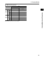
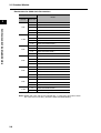
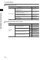
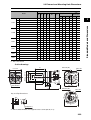
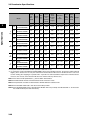
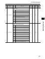
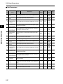
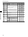
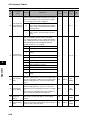
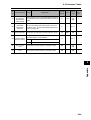
2-1 Standard Models
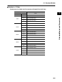
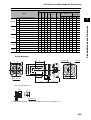
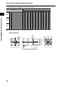
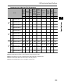
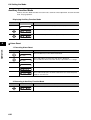
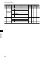
Decelerators for 2,000-r/min Servomotors
Specifications
Motor
capacity
2
Standard Models and Dimensions
1 kW
1.5 kW
2 kW
3 kW
4 kW
5 kW
7.5 kW
Gear ratio
Model
1/5
R88G-HPG32A053K0B@
1/11
R88G-HPG32A112K0SB@
1/21
R88G-HPG32A211K0SB@
1/33
R88G-HPG50A332K0SB@
1/45
R88G-HPG50A451K0SB@
1/5
R88G-HPG32A053K0B@
1/11
R88G-HPG32A112K0SB@
1/21
R88G-HPG50A213K0B@
1/33
R88G-HPG50A332K0SB@
1/5
R88G-HPG32A053K0B@
1/11
R88G-HPG32A112K0SB@
1/21
R88G-HPG50A213K0B@
1/33
R88G-HPG50A332K0SB@
1/5
R88G-HPG32A054K0B@
1/11
R88G-HPG50A115K0B@
1/21
R88G-HPG50A213K0SB@
1/25
R88G-HPG65A253K0SB@
1/5
R88G-HPG50A054K0SB@
1/11
R88G-HPG50A114K0SB@
1/20
R88G-HPG65A204K0SB@
1/25
R88G-HPG65A254K0SB@
1/5
R88G-HPG50A055K0SB@
1/11
R88G-HPG50A115K0SB@
1/20
R88G-HPG65A205K0SB@
1/25
R88G-HPG65A255K0SB@
1/5
R88G-HPG65A057K5SB@
1/12
R88G-HPG65A127K5SB@
Note 1. The standard models have a straight shaft.
Note 2. Models with a key and tap are indicated with “J” at the end of the model number
(the suffix shown in the box). (Example: R88G-HPG32A053K0BJ)
2-9
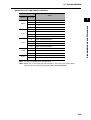
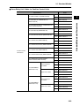
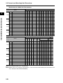
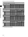
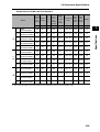
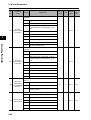
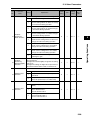
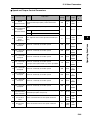
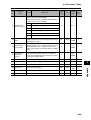
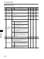
2-1 Standard Models
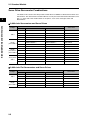
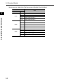
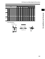
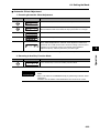
Decelerators for 1,000-r/min Servomotors
Specifications
900 W
2 kW
3 kW
4.5 kW
6 kW
Gear ratio
Model
1/5
R88G-HPG32A05900TB@
1/11
R88G-HPG32A11900TB@
1/21
R88G-HPG50A21900TB@
1/33
R88G-HPG50A33900TB@
1/5
R88G-HPG32A052K0TB@
1/11
R88G-HPG50A112K0TB@
1/21
R88G-HPG50A212K0TB@
1/25
R88G-HPG65A255K0SB@
1/5
R88G-HPG50A055K0SB@
1/11
R88G-HPG50A115K0SB@
1/20
R88G-HPG65A205K0SB@
1/25
R88G-HPG65A255K0SB@
1/5
R88G-HPG50A054K5TB@
1/12
R88G-HPG65A127K5SB@
1/20
R88G-HPG65A204K5TB@
1/5
R88G-HPG65A057K5SB@
1/12
R88G-HPG65A127K5SB@
2
Standard Models and Dimensions
Motor
capacity
Note 1. The standard models have a straight shaft.
Note 2. Models with a key and tap are indicated with “J” at the end of the model number
(the suffix shown in the box). (Example: R88G-HPG32A05900TBJ)
2-10
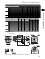
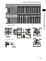
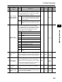
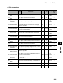
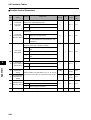
2-1 Standard Models
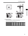
Decelerators for 3,000-r/min Flat Servomotors
Specifications
Model
Motor capacity
2
Standard Models and Dimensions
100 W
200 W
400 W
Gear ratio
1/5
R88G-HPG11B05100PB@
1/11
R88G-HPG14A11100PB@
1/21
R88G-HPG14A21100PB@
1/33
R88G-HPG20A33100PB@
1/45
R88G-HPG20A45100PB@
1/5
R88G-HPG14A05200PB@
1/11
R88G-HPG20A11200PB@
1/21
R88G-HPG20A21200PB@
1/33
R88G-HPG20A33200PB@
1/45
R88G-HPG20A45200PB@
1/5
R88G-HPG20A05400PB@
1/11
R88G-HPG20A11400PB@
1/21
R88G-HPG20A21400PB@
1/33
R88G-HPG32A33400PB@
1/45
R88G-HPG32A45400PB@
Note 1. The standard models have a straight shaft.
Note 2. Models with a key and tap are indicated with “J” at the end of the model number
(the suffix shown in the box). (Example: R88G-HPG11B05100PBJ)
2-11
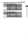
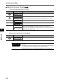
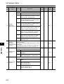
2-1 Standard Models
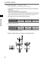
Backlash = 15’ Max.
Decelerators for 3,000-r/min Servomotors (Straight Shaft with Key)
Specifications
Model
2
Gear ratio
1/5
R88G-VRSF05B100CJ
1/9
R88G-VRSF09B100CJ
1/15
R88G-VRSF15B100CJ
1/25
R88G-VRSF25B100CJ
1/5
R88G-VRSF05B100CJ
1/9
R88G-VRSF09B100CJ
1/15
R88G-VRSF15B100CJ
1/25
R88G-VRSF25B100CJ
1/5
R88G-VRSF05B200CJ
1/9
R88G-VRSF09C200CJ
1/15
R88G-VRSF15C200CJ
1/25
R88G-VRSF25C200CJ
1/5
R88G-VRSF05C400CJ
1/9
R88G-VRSF09C400CJ
1/15
R88G-VRSF15C400CJ
1/25
R88G-VRSF25C400CJ
1/5
R88G-VRSF05C750CJ
1/9
R88G-VRSF09D750CJ
1/15
R88G-VRSF15D750CJ
1/25
R88G-VRSF25D750CJ
Standard Models and Dimensions
Motor capacity
50 W
100 W
200 W
400 W
750 W
2-12
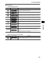
2-1 Standard Models
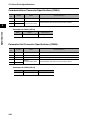
Decelerators for 3,000-r/min Flat Servomotors (Straight Shaft with Key)
Specifications
Model
Motor capacity
2
Gear ratio
1/5
R88G-VRSF05B100PCJ
1/9
R88G-VRSF09B100PCJ
1/15
R88G-VRSF15B100PCJ
1/25
R88G-VRSF25B100PCJ
1/5
R88G-VRSF05B200PCJ
1/9
R88G-VRSF09C200PCJ
1/15
R88G-VRSF15C200PCJ
1/25
R88G-VRSF25C200PCJ
1/5
R88G-VRSF05C400PCJ
1/9
R88G-VRSF09C400PCJ
1/15
R88G-VRSF15C400PCJ
1/25
R88G-VRSF25C400PCJ
Standard Models and Dimensions
100 W
200 W
400 W
2-13
2-1 Standard Models
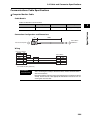
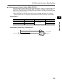
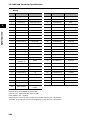
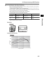
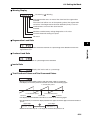
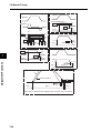
Accessories and Cables
Encoder Cables (Standard Cables)
3,000-r/min Servomotors of 50 to 750 W with an absolute encoder,
3,000-r/min Flat Servomotors of 100 to 400 W with an absolute
encoder
3,000-r/min Servomotors of 50 to 750 W with an incremental
encoder,
3,000-r/min Flat Servomotors of 100 to 400 W with an incremental
encoder
3,000-r/min Servomotors of 1 to 5 kW,
2,000-r/min Servomotors of 1 to 5 kW,
1,500-r/min Servomotors of 7.5 kW,
1,000-r/min Servomotors of 900 W to 6 kW
Model
3m
R88A-CRGA003C
5m
R88A-CRGA005C
10 m
R88A-CRGA010C
15 m
R88A-CRGA015C
20 m
R88A-CRGA020C
30 m
R88A-CRGA030C
40 m
R88A-CRGA040C
50 m
R88A-CRGA050C
3m
R88A-CRGB003C
5m
R88A-CRGB005C
10 m
R88A-CRGB010C
15 m
R88A-CRGB015C
20 m
R88A-CRGB020C
30 m
R88A-CRGB030C
40 m
R88A-CRGB040C
50 m
R88A-CRGB050C
3m
R88A-CRGC003N
5m
R88A-CRGC005N
10 m
R88A-CRGC010N
15 m
R88A-CRGC015N
20 m
R88A-CRGC020N
30 m
R88A-CRGC030N
40 m
R88A-CRGC040N
50 m
R88A-CRGC050N
2
Standard Models and Dimensions
Specifications
2-14
2-1 Standard Models
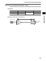
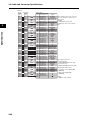
Servomotor Power Cables (Standard Cables)
Model
Specifications
For Servomotor without
brake
Standard Models and Dimensions
2
3,000-r/min Servomotors of 50 to 750 W,
3,000-r/min Flat Servomotors of 100 to
400 W
3,000-r/min Servomotors of 1 to 1.5 kW,
2,000-r/min Servomotors of 1 to 1.5 kW,
1,000-r/min Servomotors of 900 W
3,000-r/min Servomotors of 2 kW,
2,000-r/min Servomotors of 2 kW
3,000-r/min Servomotors of 3 to 5 kW,
2,000-r/min Servomotors of 3 to 5 kW,
1,000-r/min Servomotors of 2 to 4.5 kW
2-15
For Servomotor with
brake
3m
R88A-CAGA003S
---
5m
R88A-CAGA005S
---
10 m
R88A-CAGA010S
---
15 m
R88A-CAGA015S
---
20 m
R88A-CAGA020S
---
30 m
R88A-CAGA030S
---
40 m
R88A-CAGA040S
---
50 m
R88A-CAGA050S
---
3m
R88A-CAGB003S
R88A-CAGB003B
5m
R88A-CAGB005S
R88A-CAGB005B
10 m
R88A-CAGB010S
R88A-CAGB010B
15 m
R88A-CAGB015S
R88A-CAGB015B
20 m
R88A-CAGB020S
R88A-CAGB020B
30 m
R88A-CAGB030S
R88A-CAGB030B
40 m
R88A-CAGB040S
R88A-CAGB040B
50 m
R88A-CAGB050S
R88A-CAGB050B
3m
R88A-CAGC003S
R88A-CAGC003B
5m
R88A-CAGC005S
R88A-CAGC005B
10 m
R88A-CAGC010S
R88A-CAGC010B
15 m
R88A-CAGC015S
R88A-CAGC015B
20 m
R88A-CAGC020S
R88A-CAGC020B
30 m
R88A-CAGC030S
R88A-CAGC030B
40 m
R88A-CAGC040S
R88A-CAGC040B
50 m
R88A-CAGC050S
R88A-CAGC050B
3m
R88A-CAGD003S
R88A-CAGD003B
5m
R88A-CAGD005S
R88A-CAGD005B
10 m
R88A-CAGD010S
R88A-CAGD010B
15 m
R88A-CAGD015S
R88A-CAGD015B
20 m
R88A-CAGD020S
R88A-CAGD020B
30 m
R88A-CAGD030S
R88A-CAGD030B
40 m
R88A-CAGD040S
R88A-CAGD040B
50 m
R88A-CAGD050S
R88A-CAGD050B
2-1 Standard Models
Model
For Servomotor without
brake
3m
1,500-r/min Servomotors of 7.5 kW,
1,000-r/min Servomotors of 6 kW
For Servomotor with
brake
R88A-CAGE003S
---
5m
R88A-CAGE005S
---
10 m
R88A-CAGE010S
---
15 m
R88A-CAGE015S
---
20 m
R88A-CAGE020S
---
30 m
R88A-CAGE030S
---
40 m
R88A-CAGE040S
---
50 m
R88A-CAGE050S
---
2
Note There are separate connectors for power and brakes for 3,000-r/min Servomotors of 50 to
750 W, Flat Servomotors, and Servomotors of 6 kW or higher. Therefore, when a
Servomotor with a brake is used, it will require both a Power Cable for a Servomotor without
a brake and a Brake Cable.
2-16
Standard Models and Dimensions
Specifications
2-1 Standard Models
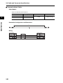
Brake Cables (Standard Cables)
Specifications
Standard Models and Dimensions
2
3,000-r/min Servomotors of 50 to 750 W,
3,000-r/min Flat Servomotors of 100 to 400 W
1,500-r/min Servomotors of 7.5 kW,
1,000-r/min Servomotors of 6 kW
2-17
Model
3m
R88A-CAGA003B
5m
R88A-CAGA005B
10 m
R88A-CAGA010B
15 m
R88A-CAGA015B
20 m
R88A-CAGA020B
30 m
R88A-CAGA030B
40 m
R88A-CAGA040B
50 m
R88A-CAGA050B
3m
R88A-CAGE003B
5m
R88A-CAGE005B
10 m
R88A-CAGE010B
15 m
R88A-CAGE015B
20 m
R88A-CAGE020B
30 m
R88A-CAGE030B
40 m
R88A-CAGE040B
50 m
R88A-CAGE050B
2-1 Standard Models
Encoder Cables (Robot Cables)
3,000-r/min Servomotors of 50 to 750 W
with an absolute encoder,
3,000-r/min Flat Servomotors of 100 to 400 W
with an absolute encoder
3,000-r/min Servomotors of 50 to 750 W
with an incremental encoder,
3,000-r/min Flat Servomotors of 100 to 400 W
with an incremental encoder
3,000-r/min Servomotors of 1 to 5 kW,
2,000-r/min Servomotors of 1 to 5 kW,
1,500-r/min Servomotors of 7.5 kW
1,000-r/min Servomotors of 900 W to 6 kW
Model
3m
R88A-CRGA003CR
5m
R88A-CRGA005CR
10 m
R88A-CRGA010CR
15 m
R88A-CRGA015CR
20 m
R88A-CRGA020CR
30 m
R88A-CRGA030CR
40 m
R88A-CRGA040CR
50 m
R88A-CRGA050CR
3m
R88A-CRGB003CR
5m
R88A-CRGB005CR
10 m
R88A-CRGB010CR
15 m
R88A-CRGB015CR
20 m
R88A-CRGB020CR
30 m
R88A-CRGB030CR
40 m
R88A-CRGB040CR
50 m
R88A-CRGB050CR
3m
R88A-CRGC003NR
5m
R88A-CRGC005NR
10 m
R88A-CRGC010NR
15 m
R88A-CRGC015NR
20 m
R88A-CRGC020NR
30 m
R88A-CRGC030NR
40 m
R88A-CRGC040NR
50 m
R88A-CRGC050NR
2-18
2
Standard Models and Dimensions
Specifications
2-1 Standard Models
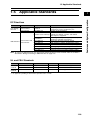
Servomotor Power Cables (Robot Cables)
Model
Specifications
Standard Models and Dimensions
2
3,000-r/min Servomotors of 50 to 750 W,
3,000-r/min Flat Servomotors of
100 to 400 W
3,000-r/min Servomotors of 1 to 1.5 kW,
2,000-r/min Servomotors of 1 to 1.5 kW,
1,000-r/min Servomotors of 900 W
3,000-r/min Servomotors of 2 kW,
2,000-r/min Servomotors of 2 kW
3,000-r/min Servomotors of 3 to 5 kW,
2,000-r/min Servomotors of 3 to 5 kW,
1,000-r/min Servomotors of 2 to 4.5 kW
For Servomotor without
brake
For Servomotor with
brake
3m
R88A-CAGA003SR
---
5m
R88A-CAGA005SR
---
10 m
R88A-CAGA010SR
---
15 m
R88A-CAGA015SR
---
20 m
R88A-CAGA020SR
---
30 m
R88A-CAGA030SR
---
40 m
R88A-CAGA040SR
---
50 m
R88A-CAGA050SR
---
3m
R88A-CAGB003SR
R88A-CAGB003BR
5m
R88A-CAGB005SR
R88A-CAGB005BR
10 m
R88A-CAGB010SR
R88A-CAGB010BR
15 m
R88A-CAGB015SR
R88A-CAGB015BR
20 m
R88A-CAGB020SR
R88A-CAGB020BR
30 m
R88A-CAGB030SR
R88A-CAGB030BR
40 m
R88A-CAGB040SR
R88A-CAGB040BR
50 m
R88A-CAGB050SR
R88A-CAGB050BR
3m
R88A-CAGC003SR
R88A-CAGC003BR
5m
R88A-CAGC005SR
R88A-CAGC005BR
10 m
R88A-CAGC010SR
R88A-CAGC010BR
15 m
R88A-CAGC015SR
R88A-CAGC015BR
20 m
R88A-CAGC020SR
R88A-CAGC020BR
30 m
R88A-CAGC030SR
R88A-CAGC030BR
40 m
R88A-CAGC040SR
R88A-CAGC040BR
50 m
R88A-CAGC050SR
R88A-CAGC050BR
3m
R88A-CAGD003SR
R88A-CAGD003BR
5m
R88A-CAGD005SR
R88A-CAGD005BR
10 m
R88A-CAGD010SR
R88A-CAGD010BR
15 m
R88A-CAGD015SR
R88A-CAGD015BR
20 m
R88A-CAGD020SR
R88A-CAGD020BR
30 m
R88A-CAGD030SR
R88A-CAGD030BR
40 m
R88A-CAGD040SR
R88A-CAGD040BR
50 m
R88A-CAGD050SR
R88A-CAGD050BR
Note There are separate connectors for power and brakes for 3,000-r/min Servomotors of 50 to
750 W and Flat Servomotors.
Therefore, when a Servomotor with a brake is used, it will require a Power Cable for a
Servomotor without a brake and a Brake Cable.
2-19
2-1 Standard Models
Brake Cables (Robot Cables)
3,000-r/min Servomotors of 50 to 750 W,
3,000-r/min Flat Servomotors of 100 to 400 W
Model
3m
R88A-CAGA003BR
5m
R88A-CAGA005BR
10 m
R88A-CAGA010BR
15 m
R88A-CAGA015BR
20 m
R88A-CAGA020BR
30 m
R88A-CAGA030BR
40 m
R88A-CAGA040BR
50 m
R88A-CAGA050BR
Communications Cable
Specifications
RS-232 Communications Cable
Model
2m
R88A-CCG002P2
0.5 m
R88A-CCG0R5P4
1m
R88A-CCG001P4
RS-485 Communications Cable
Absolute Encoder Battery Cable
Specifications
Model
0.3 m
Absolute Encoder Battery Cable
R88A-CRGD0R3C
Connectors
Specifications
Servomotor Connector for Encoder
Cable
Model
Absolute Encoder
R88A-CNG01R
Incremental Encoder
R88A-CNG02R
Control I/O Connector (CN1)
R88A-CNU11C
Encoder Connector (CN2)
R88A-CNW01R
Power Cable Connector (750 W max.)
R88A-CNG01A
Brake Cable Connector (750 W max.)
R88A-CNG01B
2-20
2
Standard Models and Dimensions
Specifications
2-1 Standard Models
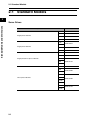
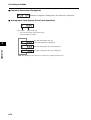
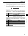
Servo Relay Units (for CN1)
Specifications
Standard Models and Dimensions
2
Servo Relay Units
Model
For CS1W-NC113/-NC133
For CJ1W-NC113/-NC133
For C200HW-NC113
XW2B-20J6-1B
For CS1W-NC213/-NC413/-NC233/-NC433
For CJ1W-NC213/-NC413/-NC233/-NC433
For C200HW-NC213/-NC413
XW2B-40J6-2B
For CJ1M-CPU21/-CPU22/-CPU23
XW2B-20J6-8A
XW2B-40J6-9A
For FQM1-MMA22
For FQM1-MMP22
XW2B-80J7-12A
For CQM1-CPU43-V1
XW2B-20J6-3B
Servo Relay Unit Cables for Servo Drives
Specifications
For Position Control Unit (XW2B-@J6-@B)
For CQM1 (XW2B-20J6-3B)
Model
1m
XW2Z-100J-B25
2m
XW2Z-200J-B25
1m
XW2Z-100J-B31
2m
XW2Z-200J-B31
1m
XW2Z-100J-B27
2m
XW2Z-200J-B27
1m
XW2Z-100J-B26
2m
XW2Z-200J-B26
For CJ1M (XW2B-20J6-8A/XW2B-40J6-9A)
Servo Drive
Cables
For FQM1-MMA22 (XW2B-80J7-12A)
For FQM1-MMP22 (XW2B-80J7-12A)
2-21
2-1 Standard Models
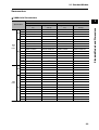
Servo Relay Unit Cables for Position Control Units
Specifications
Model
0.5 m
XW2Z-050J-A3
1m
XW2Z-100J-A3
For CS1W-NC113, C200HW-NC113
(XW2B-20J6-1B)
0.5 m
XW2Z-050J-A6
1m
XW2Z-100J-A6
For CS1W-NC213/-NC413, C200HW-NC213/
-NC413 (XW2B-20J6-2B)
0.5 m
XW2Z-050J-A7
1m
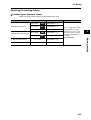
XW2Z-100J-A7
0.5 m
XW2Z-050J-A10
1m
XW2Z-100J-A10
0.5 m
XW2Z-050J-A11
1m
XW2Z-100J-A11
0.5 m
XW2Z-050J-A14
1m
XW2Z-100J-A14
0.5 m
XW2Z-050J-A15
1m
XW2Z-100J-A15
0.5 m
XW2Z-050J-A18
1m
XW2Z-100J-A18
0.5 m
XW2Z-050J-A19
1m
XW2Z-100J-A19
0.5 m
XW2Z-050J-A33
1m
XW2Z-100J-A33
0.5 m
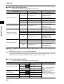
XW2Z-050J-A28
1m
XW2Z-100J-A28
2m
XW2Z-200J-A28
0.5 m
XW2Z-050J-A31
1m
XW2Z-100J-A31
2m
XW2Z-200J-A31
0.5 m
XW2Z-050J-A28
1m
XW2Z-100J-A28
2m
XW2Z-200J-A28
0.5 m
XW2Z-050J-A30
1m
XW2Z-100J-A30
2m
XW2Z-200J-A30
For CQM1-CPU43-V1 (XW2B-20J6-3B)
Standard Models and Dimensions
2
For CS1W-NC133 (XW2B-20J6-1B)
For CS1W-NC233/-NC433 (XW2B-20J6-2B)
For CJ1W-NC113 (XW2B-20J6-1B)
For CJ1W-NC213/-NC413 (XW2B-20J6-2B)
For CJ1W-NC133 (XW2B-20J6-1B)
Position Control
Unit Cables
For CJ1W-NC233/-NC433 (XW2B-20J6-2B)
For CJ1M-CPU21/-CPU22/-CPU23
(XW2B-20J6-8A/XW2B-40J6-9A)
General-purpose
I/O Cables
For FQM1-MMA22
(XW2B-80J7-12A)
Special I/O Cables
General-purpose
I/O Cables
For FQM1-MMP22
(XW2B-80J7-12A)
Special I/O Cables
2-22
2-1 Standard Models
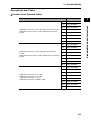
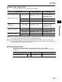
Control Cables
Specifications
2
Model
Standard Models and Dimensions
Motion Control Unit Cables for 1 axis
CS1W-MC221-V1/-MC421-V1
Motion Control Unit Cables for 2 axes
CS1W-MC221-V1/-MC421-V1
1m
R88A-CPG001M1
2m
R88A-CPG002M1
3m
R88A-CPG003M1
5m
R88A-CPG005M1
1m
R88A-CPG001M2
2m
R88A-CPG002M2
3m
R88A-CPG003M2
5m
R88A-CPG005M2
1m
R88A-CPG001S
2m
R88A-CPG002S
1m
XW2Z-100J-B24
2m
XW2Z-200J-B24
General-purpose Control Cables with Connector on One End
Connector-Terminal Block Cables
Connector Terminal Block
M3 screw type
XW2B-50G4
M3.5 screw type
XW2B-50G5
M3 screw type
XW2D-50G6
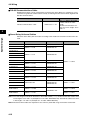
External Regeneration Resistors
Specifications
Model
Regeneration capacity: 20 W, 50 Ω (with 150°C thermal switch)
R88A-RR08050S
Regeneration capacity: 20 W, 100 Ω (with 150°C thermal switch)
R88A-RR080100S
Regeneration capacity: 70 W, 47 Ω (with 170°C thermal switch)
R88A-RR22047S
Regeneration capacity: 180 W, 20 Ω (with 200°C thermal switch)
R88A-RR50020S
Reactors
Specifications
2-23
Model
R88D-GTA5L/-GT01H
3G3AX-DL2002
R88D-GT01L/-GT02H
3G3AX-DL2004
R88D-GT02L/-GT04H
3G3AX-DL2007
R88D-GT04L/-GT08H/-GT10H
3G3AX-DL2015
R88D-GT15H
3G3AX-DL2022
R88D-GT08H/-GT10H/-GT15H
3G3AX-AL2025
R88D-GT20H/-GT30H
3G3AX-AL2055
R88D-GT50H
3G3AX-AL2110
R88D-GT75H
3G3AX-AL2220
2-1 Standard Models
Mounting Brackets (L Brackets for Rack Mounting)
Model
R88D-GTA5L/-GT01L/-GT01H/-GT02H
R88A-TK01G
R88D-GT02L/-GT04H
R88A-TK02G
R88D-GT04L/-GT08H
R88A-TK03G
R88D-GT10H/-GT15H
R88A-TK04G
2
Standard Models and Dimensions
Specifications
Absolute Encoder Backup Battery
Specifications
2,000 mA·h 3.6 V
Model
R88A-BAT01G
2-24
2-2 External and Mounting Hole Dimensions
2-2 External and Mounting Hole
Dimensions
Servo Drives
Single-phase 100 VAC: R88D-GTA5L/-GT01L (50 to 100 W)
Single-phase 200 VAC: R88D-GT01H/-GT02H (50 to 200 W)
Wall Mounting
External Dimensions
40
Mounting Hole Dimensions
70
130
4
Two, M4
AC SERVO DRIVER
UNIT No.
DATA
G
140
SP
6
28±0.5
40
2-25
5
IM
150
Standard Models and Dimensions
2
2-2 External and Mounting Hole Dimensions
Front Panel Mounting (Using Mounting Brackets)
External Dimensions
Mounting Hole Dimensions (Reference)
4
22
7
8
2.6
170±0.5
180
170
150
5.2 dia.
2
Two, M4
Square
hole
(158)*
21
130
5.2
2.6
6
R2.6
(42)*
7
* The dimensions of
the square hole are
reference values.
Dimensions for front panel mounting are references values that provide leeway.
2-26
Standard Models and Dimensions
70
2-2 External and Mounting Hole Dimensions
Single-phase 100 VAC: R88D-GT02L (200 W)
Single-phase 200 VAC: R88D-GT04H (400 W)
Wall Mounting
2
External Dimensions
70
55
Standard Models and Dimensions
Mounting Hole Dimensions
130
4
Two, M4
AC SERVO DRIVER
UNIT No.
DATA
140
G
150
SP
5
150
IM
6
43
55
Front Panel Mounting (Using Mounting Brackets)
External Dimensions
Mounting Hole Dimensions (Reference)
70
55
28
130
4
22
7
8
2.6
Two, M4
Square hole
R2.6
5.2
2.6
(57)*
7
* The dimensions of
the square hole are
reference values.
Dimensions for front panel mounting are references values that provide leeway.
2-27
(158)*
170
180
170
150
5.2 dia.
2-2 External and Mounting Hole Dimensions
Single-phase 100 VAC: R88D-GT04L (400 W)
Single-phase/Three-phase 200 VAC: R88D-GT08H (750 W)
Wall Mounting
2
External Dimensions
Mounting Hole Dimensions
170
4
Two, M4
AC SERVO DRIVER
UNIT No.
DATA
G
5
150
140
SP
150
IM
7.5
50
65
Front Panel Mounting (Using Mounting Brackets)
External Dimensions
170
4
22
20
21
Two, M4
Square hole
6
170
180
170
150
2.6
2.6
R2.6
5.2
(158)*
70
65
40
5.2 dia.
Mounting Hole Dimensions (Reference)
(67)*
20
40
* The dimensions of
the square hole are
reference values.
Dimensions for front panel mounting are references values that provide leeway.
2-28
Standard Models and Dimensions
70
65
2-2 External and Mounting Hole Dimensions
Single-phase/Three-phase 200 VAC: R88D-GT10H/-GT15H (900 W to 1.5 kW)
Wall Mounting
2
External Dimensions
Mounting Hole Dimensions
70
85
170
Standard Models and Dimensions
4
Two, M4
AC SERVO DRIVER
UNIT No.
DATA
150
140
G
7.5
5
SP
150
IM
70
85
Front Panel Mounting (Using Mounting Brackets)
External Dimensions
85
Mounting Hole Dimensions (Reference)
70
170
60
5.2
10
R2.6
170
2.6
11
40
5.2
40
Dimensions for front panel mounting are references values that provide leeway.
2-29
Square hole
6
R2.6
Four, M4
2.6
150
5.2 dia.
4
22
5.2
dia.
(158)*
40
170
180
10
(87)*
* The dimensions of
the square hole are
reference values.
2-2 External and Mounting Hole Dimensions
Three-phase 200 VAC: R88D-GT20H (2 kW)
Wall Mounting
2
External Dimensions
85
70
50
200
3.5
42.5
5.2
5.2
5.2
dia.
R2.6
R2.6
AC SERVO DRIVER
UNIT No.
DATA
5.2
dia.
R2.6
198
G
188
SP
168
IM
R2.6
5.2
3.5
5.2
42.5
17.5
50
Mounting Hole Dimensions
168
188±0.5
Four, M4
17.5
50
85
2-30
Standard Models and Dimensions
17.5
2-2 External and Mounting Hole Dimensions
Front Panel Mounting (Using Mounting Brackets)
External Dimensions
85
17.5
2
70
50
42.5
32
5.2
Standard Models and Dimensions
5.2
5.2
dia.
R2.6
200
2.6
R2.6
AC SERVO DRIVER
UNIT No.
DATA
5.2
dia.
R2.6
198
G
188
SP
168
IM
R2.6
5.2
5.2
42.5
17.5
50
Mounting Hole Dimensions (Reference)
6
Square hole
20.5
188
(176)*
Four, M4
50
(89)*
* The dimensions of
the square hole are
reference values.
Dimensions for front panel mounting are references values that provide leeway.
2-31
2-2 External and Mounting Hole Dimensions
Three-phase 200 VAC: R88D-GT30H/-GT50H (2 to 5 kW)
Wall Mounting
2
External Dimensions
65
5.2
5.2 dia.
R2.6
70
200
3.5
Standard Models and Dimensions
130
100
15
5.2
R2.6
AC SERVO DRIVER
UNIT No.
DATA
5.2
dia.
5.2
65
R2.6
15
250
G
240
SP
220
IM
R2.6
3.5
5.2
100
Mounting Hole Dimensions
Six, M4
240
220
50
15
100
130
2-32
2-2 External and Mounting Hole Dimensions
Front Panel Mounting (Using Mounting Brackets)
External Dimensions
130
100
15
2
65
5.2
5.2 dia.
Standard Models and Dimensions
R2.6
70
200
32.3
5.2
2.6
R2.6
AC SERVO DRIVER
UNIT No.
DATA
5.2
dia.
5.2
65
R2.6
250
G
240
SP
220
IM
R2.6
5.2
15
100
Mounting Hole Dimensions (Reference)
(228)*
6
Square hole
240
Six, M4
50
16
100
(132)*
* The dimensions of
the square hole are
reference values.
Dimensions for front panel mounting are references values that provide leeway.
2-33
2-2 External and Mounting Hole Dimensions
Three-phase 200 VAC: R88D-GT75H (7.5 kW)
Front Panel Mounting (Using Mounting Brackets)
2
External Dimensions
248
90
90
70
90
5.2
5.2
5.2
5.2
5.2
339.3
(4)
45.1
(2.3)
220
235
250
(4)
82.5
5.2
85
Four, 5.2 dia.
Mounting Hole Dimensions (Reference)
4.5
(226)*
Six, M4
38.5
90
235
Square hole
90
* The dimensions of
the square hole are
reference values.
(250)*
Dimensions for front panel mounting are references values that provide leeway.
2-34
Standard Models and Dimensions
37.5
2-2 External and Mounting Hole Dimensions
Servomotors
3,000-r/min Servomotors
50 W/100 W
2
R88M-G05030H(-S2)/-G10030L(-S2)/-G10030H(-S2)/-G05030H-B(S2)
INC
R88M-G05030T(-S2)/-G10030S(-S2)/-G10030T(-S2)/-G05030T-B(S2)
/-G10030S-B(S2)/-G10030T-B(S2)
ABS
Brake connector
Motor connector
Encoder
connector
LL
6
25
3
(Dimensions of shaft end
with key and tap)
40 × 40
3
LN
46
Two, 4.3 dia.
Model
Three, h: 9
1.8
14
12.5
32
30 dia., h: 7
8 dia., h: 6
200
230
Standard Models and Dimensions
/-G10030L-B(S2)/-G10030H-B(S2)
dia
.
M3 (depth: 6)
Dimensions (mm)
LL
LN
R88M-G05030@
72
26.5
R88M-G10030@
92
46.5
R88M-G05030@-B@
102
26.5
R88M-G10030@-B@
122
46.5
Note The standard models have a straight shaft. Models with a key and tap are indicated with
“S2” at the end of the model number.
2-35
2-2 External and Mounting Hole Dimensions
3,000-r/min Servomotors
200 W/400 W/750 W
R88M-G20030L(-S2)/-G40030L(-S2)/-G20030H(-S2)/-G40030H(-S2)
/-G75030H(-S2)/-G20030L-B(S2)/-G40030L-B(S2)
/-G20030H-B(S2)/-G40030H-B(S2)/-G75030H-B(S2)
2
INC
/-G75030T(-S2)/-G20030S-B(S2)/-G40030S-B(S2)
/-G20030T-B(S2)/-G40030T-B(S2)/-G75030T-B(S2)
Brake connector
Motor connector
LR
3
(Dimensions of shaft end
with key and tap)
C×C
Four, Z dia.
QK
b
dia.
t1
D1
h
D2 dia., h: 7
200
G
KL1
LL
S dia., h: 6
Encoder
connector
220
ABS
M(effective depth: L)
Model
Dimensions (mm)
LL
R88M-G20030@
79.5
R88M-G40030@
99
R88M-G75030@
LR S D1 D2 C
30
11
14
11
R88M-G20030@-B@
116
R88M-G40030@-B@
135.5
R88M-G75030@-B@
149.2 35 19 90 70 80
14
Z
70 50 60 6.5 43 4.5
112.2 35 19 90 70 80
30
G KL1
8
53
6
70 50 60 6.5 43 4.5
8
53
6
QK
18
b
h
4h9 4
22.5 5h9 5
22
6h9 6
18
4h9 4
22.5 5h9 5
22
6h9 6
M
t1
L
M4 2.5
8
M5
3
3.5
M4 2.5
M5
3
3.5
10
8
10
Note The standard models have a straight shaft. Models with a key and tap are indicated with
“S2” at the end of the model number.
2-36
Standard Models and Dimensions
R88M-G20030S(-S2)/-G40030S(-S2)/-G20030T(-S2)/-G40030T(-S2)
2-2 External and Mounting Hole Dimensions
3,000-r/min Servomotors
1 kW/1.5 kW/2 kW
R88M-G1K030T(-S2)/-G1K530T(-S2)/-G2K030T(-S2)/-G1K030T-B(S2)
/-G1K530T-B(S2)/-G2K030T-B(S2)
3
45
42
Four, Z dia.
Six, h: 9
6
D2 dia., h: 7
84
G
(Dimensions of shaft end
with key and tap)
C×C
3.5
55
ABS
KL1
LL
19 dia., h: 6
Servomotor
canon plug
Encoder
canon plug
D3
D1
.
dia
dia
.
M5 (depth: 12)
Dimensions (mm)
Model
LL
D1 D2
R88M-G1K030@
175 100 80
R88M-G1K530@
180
R88M-G2K030@
205
R88M-G1K030@-B@
200 100 80
R88M-G1K530@-B@
205
R88M-G2K030@-B@
230
C
D3
90 120
G KL1
7
98 6.6
115 95 100 135 10 103
90 120
7
Z
9
98 6.6
115 95 100 135 10 103
9
Note The standard models have a straight shaft. Models with a key and tap are indicated with
“S2” at the end of the model number.
3,000-r/min Servomotors
3 kW
R88M-G3K030T(-S2)/-G3K030T-B(S2)
9
45
41
Eight, h: 9
130
4
dia
.
111
3
(Dimensions of the shaft end
with key and tap)
120×120
55
12
ABS
162
.
dia
7
LL
22 dia., h: 6
110 dia., h: 7
Servomotor/brake
connector
Encoder
connector
84
Standard Models and Dimensions
2
145
dia.
M5 (depth: 12)
Model
Dimensions (mm)
LL
R88M-G3K030@
217
R88M-G3K030@-B@
242
Note The standard models have a straight shaft. Models with a key and tap are indicated with
“S2” at the end of the model number.
2-37
2-2 External and Mounting Hole Dimensions
3,000-r/min Servomotors
4 kW/5 kW
R88M-G4K030T(-S2)/-G5K030T(-S2)/-G4K030T-B(S2)/-G5K030T-B(S2)
ABS
2
165
.
dia
Eight, h: 9
M8 (depth: 20)
Dimensions (mm)
LL
R88M-G4K030@
240
R88M-G5K030@
280
R88M-G4K030@-B@
265
R88M-G5K030@-B@
305
Note The standard models have a straight shaft. Models with a key and tap are indicated with
“S2” at the end of the model number.
2-38
Standard Models and Dimensions
51
145 dia.
Model
55
4
Four, 9 dia.
118
6
24 dia., h: 6
110 dia., h: 7
12
(Dimensions of shaft end
with key and tap)
130×130
65
7
LL
84
Servomotor/brake
connector
Encoder
connector
2-2 External and Mounting Hole Dimensions
3,000-r/min Flat Servomotors
100 W/200 W/400 W
INC
R88M-GP10030S(-S2)/-GP20030S(-S2)/-GP40030S(-S2)/-GP10030T(-S2)
/-GP20030T(-S2)/-GP40030T(-S2)/-GP10030S-B(S2)/-GP20030S-B(S2)
/-GP40030S-B(S2)/-GP10030T-B(S2)/-GP20030T-B(S2)/-GP40030T-B(S2)
ABS
Encoder
connector
Motor connector
Brake connector
C×C
G F
S dia., h: 6
(Dimensions of shaft end
with key and tap)
Four, Z dia.
QK
D2 dia., h: 7
KL1
(7)
200
(7)
LR
h
D1
b
.
dia
t1
LL
220
Standard Models and Dimensions
2
R88M-GP10030L(-S2)/-GP20030L(-S2)/-GP40030L(-S2)/-GP10030H(-S2)
/-GP20030H(-S2)/-GP40030H(-S2)/-GP10030L-B(S2)/-GP20030L-B(S2)
/-GP40030L-B(S2)/-GP10030H-B(S2)/-GP20030H-B(S2)/-GP40030H-B(S2)
M (depth: L)
Model
Dimensions (mm)
LL
R88M-GP10030L
R88M-GP10030H
60.5
R88M-GP10030S
R88M-GP10030T
87.5
R88M-GP20030L
R88M-GP20030H
67.5
R88M-GP20030S
R88M-GP20030T
94.5
R88M-GP40030L
R88M-GP40030H
82.5
R88M-GP40030S
R88M-GP40030T
109.5
R88M-GP10030L-B@
R88M-GP10030H-B@
84.5
R88M-GP10030S-B@
R88M-GP10030T-B@
111.5
R88M-GP20030L-B@
R88M-GP20030H-B@
100
R88M-GP20030S-B@
R88M-GP20030T-B@
127
R88M-GP40030L-B@
R88M-GP40030H-B@
115
R88M-GP40030S-B@
R88M-GP40030T-B@
142
LR
S
D1 D2
C
F
G KL1
25
8
70
60
3
7
50
Z
h
t1
M
L
43 4.5 12.5 3h9
3
1.8
M3
6
18 4h9
4
2.5
M4
8
22.5 5h9
5
3
M5
10
43 4.5 12.5 3h9
3
1.8
M3
6
18 4h9
4
2.5
M4
8
22.5 5h9
5
3
M5
10
11
30
90
70
80
5
8
8
70
50
60
3
7
11
30
90
14
70
80
5
8
b
53 5.5
14
25
QK
53 5.5
Note The standard models have a straight shaft. Models with a key and tap are indicated with “S2” at the end of
the model number.
2-39
2-2 External and Mounting Hole Dimensions
2,000-r/min Servomotors
1 kW/1.5 kW
Four, 9 dia.
45
41
Eight, h: 9
4
6
7
12
2
(Dimensions of shaft end
with key and tap)
130 × 130
55
22 dia., h: 6
110 dia., h: 7
118
LL
84
Servomotor/brake
connector
Encoder
connector
ABS
165
dia.
145
dia
.
M5 (depth: 12)
Dimensions (mm)
Model
LL
150
R88M-G1K020@
R88M-G1K520@
175
R88M-G1K020@-B@
200
R88M-G1K520@-B@
Note The standard models have a straight shaft. Models with a key and tap are indicated with
“S2” at the end of the model number.
2,000-r/min Servomotors
2 kW/3 kW
R88M-G2K020T(-S2)/-G3K020T(-S2)/-G2K020T-B(S2)/-G3K020T-B(S2)
Four, 9 dia.
LW
QK
Eight, h: 9
7
110 dia., h: 7
4
6
118
12
(Dimensions of shaft end
with key and tap)
130 × 130
LR
S dia., h: 6
LL
84
Servomotor/brake
connector
Encoder
connector
ABS
165
dia.
145
dia
.
M (depth: L)
Model
Dimensions (mm)
LL
LR
S
LW QK
M
L
R88M-G2K020@
200 55
22
45
41 M5 12
R88M-G3K020@
250 65
24
55
51 M8 20
R88M-G2K020@-B@
225 55
22
45
41 M5 12
R88M-G3K020@-B@
275 65
24
55
51 M8 20
Note The standard models have a straight shaft. Models with a key and tap are indicated with
“S2” at the end of the model number.
2-40
Standard Models and Dimensions
R88M-G1K020T(-S2)/-G1K520T(-S2)/-G1K020T-B(S2)/-G1K520T-B(S2)
2-2 External and Mounting Hole Dimensions
2,000-r/min Servomotors
4 kW/5 kW
R88M-G4K020T(-S2)/-G5K020T(-S2)/-G4K020T-B(S2)/-G5K020T-B(S2)
C×C
LR
Four, Z dia.
QK
b
h
D2 dia., h: 7
t1
3.2
84
18
(Dimensions of shaft end
with key and tap)
KL1
LL
S dia.,h: 6
Servomotor/brake
connector
Encoder
connector
Standard Models and Dimensions
2
ABS
D3
dia.
D1
dia
.
M (depth: L)
Model
Dimensions (mm)
LL
LR
S
D1
D2
C
D3 KL1
Z
QK
b
h
t1
M
51
M8 20
R88M-G4K020@
242 65
28 165 130 150 190 128 11
8h9
7
4
R88M-G5K020@
225 70
35 200 114.3 176 233 143 13.5 50 10h9
8
5 M12 25
R88M-G4K020@-B@
267 65
28 165 130 150 190 128 11
8h9
7
4
R88M-G5K020@-B@
250 70
35 200 114.3 176 233 143 13.5 50 10h9
8
5 M12 25
51
M8 20
Note The standard models have a straight shaft. Models with a key and tap are indicated with
“S2” at the end of the model number.
2-41
L
2-2 External and Mounting Hole Dimensions
1,500-r/min Servomotors
7.5 kW
R88M-G7K515T(-S2)/-G7K515T-B(S2)
ABS
Brake connector
96
90
8
233
200
Model
12, h: 9
Four, 13.5 dia.
.
dia
dia
.
M16 (depth:32)
Dimensions (mm)
LL
R88M-G7K515@
340.5
R88M-G7K515@-B@
380.5
Note The standard models have a straight shaft. Models with a key and tap are indicated with
“S2” at the end of the model number.
2-42
Standard Models and Dimensions
176 × 176
84
24 3.2
42 dia., h: 6
Encoder
connector
113
114.3 dia., h: 7
183
LL
2
(Dimensions of shaft end
with key and tap)
Eye-bolt
Nominal diameter: 10
5
Motor
connector
2-2 External and Mounting Hole Dimensions
1,000-r/min Servomotors
900 W/2 kW
R88M-G90010T(-S2)/-G2K010T(-S2)/-G90010T-B(S2)/-G2K010T-B(S2)
2
ABS
Encoder connector
Servomotor/brake connector
LR
(Dimensions of shaft end
with key and tap)
S dia., h: 6
C×C
QK
Four, Z dia.
b
h
D2 dia., h: 7
t1
KL1
G F
84
D3
.
D1
dia
.
dia
M (depth: L)
Model
R88M-G90010@
Dimensions (mm)
LL
LR
175 70
S
D1
D2
C
D3
F
G KL1
Z
QK
b
h
t1
M
L
22 145 110 130 165
6
12 118
9
41
8h9
7
4
M5
12
R88M-G2K010@
182 80
35 200 114.3 176 233 3.2 18 143 13.5 50 10h9
8
5
M12 25
R88M-G90010@-B@
200 70
22 145 110 130 165
8h9
7
4
M5
R88M-G2K010@-B@
207 80
35 200 114.3 176 233 3.2 18 143 13.5 50 10h9
8
5
M12 25
6
12 118
9
41
12
Note The standard models have a straight shaft. Models with a key and tap are indicated with “S2” at the end of
the model number.
1,000-r/min Servomotors
3 kW
R88M-G3K010T(-S2)/-G3K010T-B(S2)
LL
80
Model
50
10, h: 9
5
Four, 13.5 dia.
8
114.3 dia., h: 7
18 3.2
176 × 176
143
Encoder connector
ABS
(Dimensions of shaft end
with key and tap)
35 dia., h: 6
Servomotor/brake
connector
84
Standard Models and Dimensions
LL
233
.
dia
200
dia
.
M12 (depth: 25)
Dimensions (mm)
LL
R88M-G3K010@
222
R88M-G3K010@-B@
271
Note The standard models have a straight shaft. Models with a key and tap are indicated with
“S2” at the end of the model number.
2-43
2-2 External and Mounting Hole Dimensions
1,000-r/min Servomotors
4.5 kW
R88M-G4K510T(-S2)/-G4K510T-B(S2)
176 × 176
90
12, h: 9
5
Four, 13.5 dia.
8
143
24 3.2
42 dia., h: 6
Nominal
diameter: 10
233
.
dia
200
dia
.
M16 (depth: 32)
Dimensions (mm)
Model
LL
R88M-G4K510@
300.5
R88M-G4K510@-B@
337.5
Note The standard models have a straight shaft. Models with a key and tap are indicated with
“S2” at the end of the model number.
1,000-r/min Servomotors
6 kW
R88M-G6K010T(-S2)/-G6K010T-B(S2)
ABS
Brake connector
(Dimensions of shaft end
with key and tap)
Eye-bolt
Nominal diameter: 10
176 × 176
96
90
114.3 dia., h: 7
Model
12, h: 9
Four, 13.5 dia.
233
200
.
5
42 dia., h: 6
Encoder
connector
8
Motor
connector
dia
dia
.
M16 (depth: 32)
Dimensions (mm)
LL
R88M-G6K010@
340.5
R88M-G6K010@-B@
380.5
Note The standard models have a straight shaft. Models with a key and tap are indicated with
“S2” at the end of the model number.
2-44
Standard Models and Dimensions
113
Eye-bolt
84
Encoder connector
LL
2
(Dimensions of shaft end
with key and tap)
114.3 dia., h: 7
Servomotor/brake
connector
ABS
2-2 External and Mounting Hole Dimensions
Parameter Unit Dimensions
R88A-PR02G Hand-held Parameter Unit
2
(62)
M3 (depth: 5)
(114)
Standard Models and Dimensions
(15)
(24)
(15)
(1500)
2-45
Mini DIN 8-pin
MD connector
2-2 External and Mounting Hole Dimensions
Servomotor and Decelerator Combinations
3,000-r/min Servomotors
1/5
1/11
(1/9 for flange size
No.11)
1/21
1/33
1/45
2
R88MG05030@
R88GR88GHPG11B05100B@
HPG11B09050B@
(Also used with
(Gear ratio 1/9)
R88M-G10030@)
R88GHPG14A21100B@ R88GR88G(Also used with
HPG14A33050B@ HPG14A45050B@
R88M-G10030@)
R88MG10030@
R88GR88GR88GR88GR88GHPG11B05100B@ HPG14A11100B@ HPG14A21100B@ HPG20A33100B@ HPG20A45100B@
R88MG20030@
R88GR88GR88GR88GR88GHPG14A05200B@ HPG14A11200B@ HPG20A21200B@ HPG20A33200B@ HPG20A45200B@
R88MG40030@
R88GR88GR88GR88GR88GHPG14A05400B@ HPG20A11400B@ HPG20A21400B@ HPG32A33400B@ HPG32A45400B@
R88MG75030@
R88GR88GR88GR88GR88GHPG20A05750B@ HPG20A11750B@ HPG32A21750B@ HPG32A33750B@ HPG32A45750B@
R88MG1K030T
R88GR88GR88GR88GR88GHPG32A051K0B@ HPG32A111K0B@ HPG32A211K0B@ HPG32A331K0B@ HPG50A451K0B@
R88MG1K530T
R88GHPG32A052K0B@
(Also used with
R88M-G2K030T)
R88MG2K030T
R88GR88GR88GR88G--HPG32A052K0B@ HPG32A112K0B@ HPG50A212K0B@ HPG50A332K0B@
R88MG3K030T
R88GR88GR88G--HPG32A053K0B@ HPG50A113K0B@ HPG50A213K0B@
---
R88MG4K030T
R88GHPG50A115K0B@
R88G--HPG32A054K0B@ (Also used with
R88M-G5K030T)
---
---
R88MG5K030T
R88GR88G--HPG50A055K0B@ HPG50A115K0B@
---
---
R88GHPG32A112K0B@ R88G(Also used with
HPG32A211K5B@
R88M-G2K030T)
R88GHPG50A332K0B@ R88G(Also used with
HPG50A451K5B@
R88M-G2K030T)
2-46
Standard Models and Dimensions
Motor model
2-2 External and Mounting Hole Dimensions
3,000-r/min Flat Servomotors
Motor
model
2
1/5
1/11
1/21
1/33
1/45
R88GR88GR88GR88GR88GR88MGP10030@ HPG11B05100PB@ HPG14A11100PB@ HPG14A21100PB@ HPG20A33100PB@ HPG20A45100PB@
Standard Models and Dimensions
R88MR88GR88GR88GR88GR88GGP20030@ HPG14A05200PB@ HPG20A11200PB@ HPG20A21200PB@ HPG20A33200PB@ HPG20A45200PB@
R88MR88GR88GR88GR88GR88GGP40030@ HPG20A05400PB@ HPG20A11400PB@ HPG20A21400PB@ HPG32A33400PB@ HPG32A45400PB@
2,000-r/min Servomotors
Motor
model
1/5
1/11
(1/12 for flange size
No.65)
1/21
(1/20 for flange size
No.65)
1/33
(1/25 for flange size
No.65)
1/45
R88MG1K020T
R88GHPG32A053K0B@
(Also used with
R88M-G3K030T)
R88GHPG32A112K0SB@ R88G(Also used with
HPG32A211K0SB@
R88M-G2K020T)
R88GHPG50A332K0SB@ R88G(Also used with
HPG50A451K0SB@
R88M-G2K020T)
R88MG1K520T
R88GHPG32A053K0B@
(Also used with
R88M-G3K030T)
R88GHPG32A112K0SB@
(Also used with
R88M-G2K020T)
R88GHPG50A213K0B@
(Also used with
R88M-G3K030T)
R88GHPG50A332K0SB@
--(Also used with
R88M-G2K020T)
R88MG2K020T
R88GHPG32A053K0B@
(Also used with
R88M-G3K030T)
R88GHPG50A213K0B@
R88GHPG32A112K0SB@ (Also used with
R88M-G3K030T)
R88G--HPG50A332K0SB@
R88MG3K020T
R88GHPG32A054K0B@
(Also used with
R88M-G4K030T)
R88GHPG50A115K0B@
(Also used with
R88M-G5K030T)
R88MG4K020T
R88GR88GR88GR88G--HPG50A054K0SB@ HPG50A114K0SB@ HPG65A204K0SB@ HPG65A254K0SB@
R88MG5K020T
R88GR88GR88GR88G--HPG50A055K0SB@ HPG50A115K0SB@ HPG65A205K0SB@ HPG65A255K0SB@
R88MG7K515T
R88GR88G--HPG65A057K5SB@ HPG65A127K5SB@
2-47
R88GR88G--HPG50A213K0SB@ HPG65A253K0SB@
---
---
2-2 External and Mounting Hole Dimensions
1,000-r/min Servomotors
1/5
1/11
(1/12 for flange size
No.65)
1/21
(1/20 for flange size
No.65)
1/33
(1/25 for flange size
No.65)
R88MG90010T
R88GHPG32A05900TB@
R88GHPG32A11900TB@
R88GHPG50A21900TB@
R88GHPG50A33900TB@
R88MG2K010T
R88GHPG32A052K0TB@
R88GHPG50A112K0TB@
R88GHPG50A212K0TB@
R88GHPG65A255K0SB@
(Also used with R88MG5K020T)
R88MG3K010T
R88GHPG50A055K0SB@
(Also used with R88MG5K020T)
R88GHPG50A115K0SB@
(Also used with R88MG5K020T)
R88GHPG65A205K0SB@
(Also used with R88MG5K020T)
R88GHPG65A255K0SB@
(Also used with R88MG5K020T)
R88MG4K510T
R88GHPG50A054K5TB@
R88GHPG65A127K5SB@ R88G(Also used with R88M- HPG65A204K5TB@
G7K515T)
---
R88MG6K010T
R88GHPG65A057K5SB@
(Also used with R88MG7K515T)
R88GHPG65A127K5SB@
--(Also used with R88MG7K515T)
---
2
Standard Models and Dimensions
Motor model
2-48
2-2 External and Mounting Hole Dimensions
Decelerator Dimensions
Backlash = 3’ Max.
Decelerators for 3,000-r/min Servomotors
2
Standard Models and Dimensions
Model
Dimensions (mm)
LM
LR
C1
C2
D1
D2
D3
D4
D5
E
F1
F2
G
1/5 R88G-HPG11B05100B@
1/9 R88G-HPG11B09050B@
50 W 1/21 R88G-HPG14A21100B@
1/33 R88G-HPG14A33050B@
1/45 R88G-HPG14A45050B@
1/5 R88G-HPG11B05100B@
1/11 R88G-HPG14A11100B@
100 W 1/21 R88G-HPG14A21100B@
1/33 R88G-HPG20A33100B@
39.5
39.5
64.0
64.0
64.0
39.5
64.0
64.0
66.5
42
42
58
58
58
42
58
58
80
1/45 R88G-HPG20A45100B@
1/5 R88G-HPG14A05200B@
1/11 R88G-HPG14A11200B@
200 W 1/21 R88G-HPG20A21200B@
66.5
64.0
64.0
71.0
80
58
58
80
40 40×40
40 40×40
60 60×60
60 60×60
60 60×60
40 40×40
60 60×60
60 60×60
90 55 dia.
90 55 dia.
60 60×60
60 60×60
90 89 dia.
46
46
70
70
70
46
70
70
46
46
46
46
46
46
46
46
40.0
40.0
56.0
56.0
56.0
40.0
56.0
56.0
39.5
39.5
55.5
55.5
55.5
39.5
55.5
55.5
29
29
40
40
40
29
40
40
27
27
37
37
37
27
37
37
2.2
2.2
2.5
2.5
2.5
2.2
2.5
2.5
15
15
21
21
21
15
21
21
5
5
8
8
8
5
8
8
105
105
70
70
46
46
70
70
85.0
85.0
56.0
56.0
84.0
84.0
55.5
55.5
59
59
40
40
53
53
37
37
7.5
7.5
2.5
2.5
27
27
21
21
10
10
8
8
1/33 R88G-HPG20A33200B@ 71.0
1/45 R88G-HPG20A45200B@ 71.0
80
80
105
90 89 dia. 105
90 89 dia. 105
70
70
70
85.0 84.0
85.0 84.0
85.0 84.0
59
59
59
53
53
53
7.5
7.5
7.5
27
27
27
10
10
10
Dimensions (mm)
Model
1/5
1/9
50 W 1/21
1/33
1/45
1/5
1/11
100 W 1/21
1/33
1/45
1/5
1/11
200 W 1/21
1/33
1/45
R88G-HPG11B05100B@
R88G-HPG11B09050B@
R88G-HPG14A21100B@
R88G-HPG14A33050B@
R88G-HPG14A45050B@
R88G-HPG11B05100B@
R88G-HPG14A11100B@
R88G-HPG14A21100B@
R88G-HPG20A33100B@
R88G-HPG20A45100B@
R88G-HPG14A05200B@
R88G-HPG14A11200B@
R88G-HPG20A21200B@
R88G-HPG20A33200B@
R88G-HPG20A45200B@
S
T
Z1
Z2
AT*1
8
8
16
16
16
8
16
16
25
25
16
16
25
25
25
20
20
28
28
28
20
28
28
42
42
28
28
42
42
42
3.4
3.4
5.5
5.5
5.5
3.4
5.5
5.5
9.0
9.0
5.5
5.5
9.0
9.0
9.0
M4×9
M4×9
M4×10
M4×10
M4×10
M4×9
M4×10
M4×10
M4×10
M4×10
M4×10
M4×10
M4×10
M4×10
M4×10
M3
M3
M3
M3
M3
M3
M3
M3
M4
M4
M4
M4
M4
M4
M4
Key dimensions
QK
15
15
25
25
25
15
25
25
36
36
25
25
36
36
36
b
3
3
5
5
5
3
5
5
8
8
5
5
8
8
8
h
3
3
5
5
5
3
5
5
7
7
5
5
7
7
7
t1
1.8
1.8
3
3
3
1.8
3
3
4.0
4.0
3
3
4.0
4.0
4.0
Tap
dimensions
M
L
M3
6
M3
6
M4
8
M4
8
M4
8
M3
6
M4
8
M4
8
M6
12
M6
12
M4
8
M4
8
M6
12
M6
12
M6
12
Note 1. The standard models have a straight shaft.
Note 2. Models with a key and tap are indicated with “J” at the end of the model number (the suffix shown in the
box). (Example: R88G-HPG11B05100BJ)
2-49
2-2 External and Mounting Hole Dimensions
Dimensions (mm)
LM
LR
C1
C2
D1
D2
D3
D4
D5
E
F1
F2
G
1/5 R88G-HPG14A05400B@ 64.0
58
60
60×60
70
70
56.0
55.5
40
37
2.5
21
8
1/11 R88G-HPG20A11400B@ 71.0
80
90
89 dia. 105
70
85.0
84.0
59
53
7.5
27
10
400 W 1/21 R88G-HPG20A21400B@ 71.0
80
90
89 dia. 105
70
85.0
84.0
59
53
7.5
27
10
1/33 R88G-HPG32A33400B@ 104.0 133 120 122 dia. 135
70 115.0 114.0 84
98 12.5 35
13
1/45 R88G-HPG32A45400B@ 104.0 133 120 122 dia. 135
70 115.0 114.0 84
98 12.5 35
13
1/5 R88G-HPG20A05750B@ 78.0
80
90
80×80
105
90
85.0
84.0
59
53
7.5
27
10
1/11 R88G-HPG20A11750B@ 78.0
80
90
80×80
105
90
85.0
84.0
59
53
7.5
27
10
750 W 1/21 R88G-HPG32A21750B@ 104.0 133 120 122 dia. 135
90 115.0 114.0 84
98 12.5 35
13
1/33 R88G-HPG32A33750B@ 104.0 133 120 122 dia. 135
90 115.0 114.0 84
98 12.5 35
13
1/45 R88G-HPG32A45750B@ 104.0 133 120 122 dia. 135
90 115.0 114.0 84
98 12.5 35
13
Dimensions (mm)
Model
S
T
Z1
Z2
Tap
dimensions
Key dimensions
AT*1
QK
b
h
t1
M
L
1/5 R88G-HPG14A05400B@
16
28
5.5
M4×10
M4
25
5
5
3
M4
8
1/11 R88G-HPG20A11400B@
25
42
9.0
M4×10
M4
36
8
7
4.0
M6
12
400 W 1/21 R88G-HPG20A21400B@
25
42
9.0
M4×10
M4
36
8
7
4.0
M6
12
1/33 R88G-HPG32A33400B@
40
82
11.0 M4×10
M4
70
12
8
5.0
M10
20
1/45 R88G-HPG32A45400B@
40
82
11.0 M4×10
M4
70
12
8
5.0
M10
20
1/5 R88G-HPG20A05750B@
25
42
9.0
M5×12
M4
36
8
7
4.0
M6
12
1/11 R88G-HPG20A11750B@
25
42
9.0
M5×12
M4
36
8
7
4.0
M6
12
750 W 1/21 R88G-HPG32A21750B@
40
82
11.0 M5×12
M6
70
12
8
5.0
M10
20
1/33 R88G-HPG32A33750B@
40
82
11.0 M5×12
M6
70
12
8
5.0
M10
20
1/45 R88G-HPG32A45750B@
40
82
11.0 M5×12
M6
70
12
8
5.0
M10
20
*1. This is the set bolt.
Outline Drawings
C1 × C1
Set bolt (AT)
E
D2 dia.
D3 dia.,h: 7
D4 dia.
D5 dia.
S dia.,h: 7
D1 dia.
Four, Z2
T
F1
C2 × C2
Four, Z1 dia.
F2
LR
G
LM
Set bolt (AT)
Four, Z2
Key and Tap Dimensions
D2 dia.
QK
t1
h
b
M (depth: L)
C2 dia.
2-50
2
Standard Models and Dimensions
Model
2-2 External and Mounting Hole Dimensions
Model
1/5 R88G-HPG32A051K0B@
1/11 R88G-HPG32A111K0B@
2
1 kW 1/21 R88G-HPG32A211K0B@
1/33 R88G-HPG32A331K0B@
1/45 R88G-HPG50A451K0B@
Standard Models and Dimensions
1/5 R88G-HPG32A052K0B@
1/11 R88G-HPG32A112K0B@
1.5 kW 1/21 R88G-HPG32A211K5B@
E
F1
F2
98 12.5 35
98 12.5 35
98 12.5 35
122
dia.
104 133 120
135 100 115 114 84 98 12.5 35
123 156 170 170 dia. 190 100 165 163 122 103 12.0 53
110 133 120 135 dia. 135 115 115 114 84 98 12.5 35
110 133 120 135 dia. 135 115 115 114 84 98 12.5 35
110 133 120 135 dia. 135 115 115 114 84 98 12.5 35
1/33 R88G-HPG50A332K0B@
123 156 170 170 dia. 190 115 165 163 122 103 12.0 53
1/5 R88G-HPG32A053K0B@
1/21 R88G-HPG50A213K0B@
107 133 120 130×130 135 145 115 114 84 98 12.5 35
123 156 170 170 dia. 190 145 165 163 122 103 12.0 53
123 156 170 170 dia. 190 145 165 163 122 103 12.0 53
1/5 R88G-HPG32A052K0B@
1/11 R88G-HPG32A112K0B@
3 kW 1/11 R88G-HPG50A113K0B@
5 kW
C1
1/21 R88G-HPG50A212K0B@
1/45 R88G-HPG50A451K5B@
4 kW
LR
123 156 170 170 dia. 190 115 165 163 122 103 12.0 53
123 156 170 170 dia. 190 115 165 163 122 103 12.0 53
110 133 120 135 dia. 135 115 115 114 84 98 12.5 35
110 133 120 135 dia. 135 115 115 114 84 98 12.5 35
123 156 170 170 dia. 190 115 165 163 122 103 12.0 53
1/33 R88G-HPG50A332K0B@
2 kW
Dimensions (mm)
C2
D1 D2 D3 D4 D5
104 133 120 122 dia. 135 100 115 114 84
104 133 120 122 dia. 135 100 115 114 84
104 133 120 122 dia. 135 100 115 114 84
LM
1/5 R88G-HPG32A054K0B@
129 133 120 130×130 135 145 115 114
1/11 R88G-HPG50A115K0B@
149 156 170 130×130 190 145 165 163 122 103 12.0 53
1/5 R88G-HPG50A055K0B@
149 156 170 130×130 190 145 165 163 122 103 12.0 53
1/11 R88G-HPG50A115K0B@
149 156 170 130×130 190 145 165 163 122 103 12.0 53
84
98 12.5 35
Note 1. The standard models have a straight shaft.
Note 2. Models with a key and tap are indicated with “J” at the end of the model number (the suffix shown in the
box). (Example: R88G-HPG32A051K0BJ)
2-51
2-2 External and Mounting Hole Dimensions
Dimensions (mm)
S
T
Z1
Z2
AT*1
QK
b
h
t1
Tap
dimensions
M
L
1/5 R88G-HPG32A051K0B@
13
40
82
11
M6×12
M6
70
12
8
5.0
M10
20
1/11 R88G-HPG32A111K0B@
13
40
82
11
M6×12
M6
70
12
8
5.0
M10
20
1 kW 1/21 R88G-HPG32A211K0B@
13
40
82
11
M6×12
M6
70
12
8
5.0
M10
20
1/33 R88G-HPG32A331K0B@
13
40
82
11
M6×12
M6
70
12
8
5.0
M10
20
1/45 R88G-HPG50A451K0B@
16
50
82
14
M6×10
M6
70
14
9
5.5
M10
20
1/5 R88G-HPG32A052K0B@
13
40
82
11
M8×10
M6
70
12
8
5.0
M10
20
Key dimensions
1/11 R88G-HPG32A112K0B@
13
40
82
11
M8×10
M6
70
12
8
5.0
M10
20
1.5 kW 1/21 R88G-HPG32A211K5B@
13
40
82
11
M8×10
M6
70
12
8
5.0
M10
20
1/33 R88G-HPG50A332K0B@
16
50
82
14
M8×10
M6
70
14
9
5.5
M10
20
1/45 R88G-HPG50A451K5B@
16
50
82
14
M8×10
M6
70
14
9
5.5
M10
20
1/5 R88G-HPG32A052K0B@
13
40
82
11
M8×10
M6
70
12
8
5.0
M10
20
1/11 R88G-HPG32A112K0B@
13
40
82
11
M8×10
M6
70
12
8
5.0
M10
20
1/21 R88G-HPG50A212K0B@
16
50
82
14
M8×10
M6
70
14
9
5.5
M10
20
1/33 R88G-HPG50A332K0B@
16
50
82
14
M8×10
M6
70
14
9
5.5
M10
20
1/5 R88G-HPG32A053K0B@
13
40
82
11
M8×18
M6
70
12
8
5.0
M10
20
3 kW 1/11 R88G-HPG50A113K0B@
16
50
82
14
M8×16
M6
70
14
9
5.5
M10
20
1/21 R88G-HPG50A213K0B@
16
50
82
14
M8×16
M6
70
14
9
5.5
M10
20
2 kW
4 kW
5 kW
1/5 R88G-HPG32A054K0B@
13
40
82
11
M8×25
M6
70
12
8
5.0
M10
20
1/11 R88G-HPG50A115K0B@
16
50
82
14
M8×25
M6
70
14
9
5.5
M10
20
1/5 R88G-HPG50A055K0B@
16
50
82
14
M8×25
M6
70
14
9
5.5
M10
20
1/11 R88G-HPG50A115K0B@
16
50
82
14
M8×25
M6
70
14
9
5.5
M10
20
*1. This is the set bolt.
Outline Drawings
E
Set bolt (AT)
Four, Z2
D2 dia.
D4 dia.
D5 dia.
S dia.,h: 7
D1 dia.
D3 dia.,h: 7 *2
C1 × C1
F1
T
Four, Z1 dia.
C2 × C2
F2 G
LR
LM
Set bolt (AT)
Four, Z2
Key and Tap Dimensions
D2 dia.
QK
t1
h
b
M (depth: L)
C2 dia.
*2. With the R88G-HPG50@, the height tolerance is 8 mm (D3 dia., h: 8).
2-52
2
Standard Models and Dimensions
G
Model
2-2 External and Mounting Hole Dimensions
Decelerators for 2,000-r/min Servomotors
Dimensions (mm)
D1 D2 D3 D4
D5
E
1/5 R88G-HPG32A053K0B@
107 133 120 130×130 135 145 115 114
84
98 12.5 35
1/11 R88G-HPG32A112K0SB@
107 133 120 130×130 135 145 115 114
84
98 12.5 35
1 kW 1/21 R88G-HPG32A211K0SB@
107 133 120 130×130 135 145 115 114
84
98 12.5 35
Model
Standard Models and Dimensions
2
1.5 kW
2 kW
3 kW
LM
LR
C1
C2
F1
F2
1/33 R88G-HPG50A332K0SB@
123 156 170 170 dia. 190 145 165 163 122 103 12.0 53
1/45 R88G-HPG50A451K0SB@
123 156 170 170 dia. 190 145 165 163 122 103 12.0 53
1/5 R88G-HPG32A053K0B@
107 133 120 130×130 135 145 115 114
84
98 12.5 35
1/11 R88G-HPG32A112K0SB@
107 133 120 130×130 135 145 115 114
84
98 12.5 35
1/21 R88G-HPG50A213K0B@
123 156 170 170 dia. 190 145 165 163 122 103 12.0 53
1/33 R88G-HPG50A332K0SB@
123 156 170 170 dia. 190 145 165 163 122 103 12.0 53
1/5 R88G-HPG32A054K0B@
129 133 120 130×130 135 145 115 114
1/11 R88G-HPG50A115K0B@
149 156 170 130×130 190 145 165 163 122 103 12.0 53
1/21 R88G-HPG50A213K0SB@
149 156 170 130×130 190 145 165 163 122 103 12.0 53
1/25 R88G-HPG65A253K0SB@
231 222 230 130×130 260 145 220 214 168 165 12.0 57
84
98 12.5 35
Dimensions (mm)
G
S
T
Z1
Z2
AT*1
QK
b
h
Tap
dimensions
t1
M
L
1/5 R88G-HPG32A053K0B@
13
40
82
11
M8×18
M6
70
12
8
5.0 M10
20
Model
Key dimensions
1/11 R88G-HPG32A112K0SB@
13
40
82
11
M8×18
M6
70
12
8
5.0 M10
20
1 kW 1/21 R88G-HPG32A211K0SB@
13
40
82
11
M8×18
M6
70
12
8
5.0 M10
20
1/33 R88G-HPG50A332K0SB@
16
50
82
14
M8×16
M6
70
14
9
5.5 M10
20
1/45 R88G-HPG50A451K0SB@
16
50
82
14
M8×16
M6
70
14
9
5.5 M10
20
1/5 R88G-HPG32A053K0B@
13
40
82
11
M8×18
M6
70
12
8
5.0 M10
20
1/11 R88G-HPG32A112K0SB@
13
40
82
11
M8×18
M6
70
12
8
5.0 M10
20
1/21 R88G-HPG50A213K0B@
16
50
82
14
M8×16
M6
70
14
9
5.5 M10
20
1/33 R88G-HPG50A332K0SB@
16
50
82
14
M8×16
M6
70
14
9
5.5 M10
20
1/5 R88G-HPG32A053K0B@
13
40
82
11
M8×18
M6
70
12
8
5.0 M10
20
1/11 R88G-HPG32A112K0SB@
13
40
82
11
M8×18
M6
70
12
8
5.0 M10
20
1/21 R88G-HPG50A213K0B@
16
50
82
14
M8×16
M6
70
14
9
5.5 M10
20
1/33 R88G-HPG50A332K0SB@
16
50
82
14
M8×16
M6
70
14
9
5.5 M10
20
1/5 R88G-HPG32A054K0B@
13
40
82
11
M8×25
M6
70
12
8
5.0 M10
20
1/11 R88G-HPG50A115K0B@
16
50
82
14
M8×25
M6
70
14
9
5.5 M10
20
1/21 R88G-HPG50A213K0SB@
16
50
82
14
M8×25
M6
70
14
9
5.5 M10
20
1/25 R88G-HPG65A253K0SB@
25
80 130 18
M8×25
M8 110 22
14 9.0 M16
35
1.5 kW
2 kW
3 kW
Note 1. The standard models have a straight shaft.
Note 2. Models with a key and tap are indicated with “J” at the end of the model number (the suffix shown in the
box). (Example: R88G-HPG32A053K0BJ)
2-53
2-2 External and Mounting Hole Dimensions
4 kW
5 kW
LR
C1
Dimensions (mm)
D1 D2 D3 D4
C2
D5
E
F1
F2
1/5 R88G-HPG50A054K0SB@
149
156 170 180×180 190 165 165 163 122 103 12.0 53
1/11 R88G-HPG50A114K0SB@
149
156 170 180×180 190 165 165 163 122 103 12.0 53
1/20 R88G-HPG65A204K0SB@
231
222 230 180×180 260 165 220 214 168 165 12.0 57
1/25 R88G-HPG65A254K0SB@
231
222 230 180×180 260 165 220 214 168 165 12.0 57
1/5 R88G-HPG50A055K0SB@
149
156 170 180×180 190 200 165 163 122 103 12.0 53
1/11 R88G-HPG50A115K0SB@
149
156 170 180×180 190 200 165 163 122 103 12.0 53
1/20 R88G-HPG65A205K0SB@
231
222 230 180×180 260 200 220 214 168 165 12.0 57
231
222 230 180×180 260 200 220 214 168 165 12.0 57
1/25 R88G-HPG65A255K0SB@
7.5 kW
LM
1/5 R88G-HPG65A057K5SB@
184.5 222 230 180×180 260 200 220 214 168 165 12.0 57
1/12 R88G-HPG65A127K5SB@
254.5 222 230 180×180 260 200 220 214 168 165 12.0 57
Dimensions (mm)
Model
4 kW
5 kW
7.5 kW
G
S
T
Z1
AT*1
Z2
Key dimensions
QK
b
h
t1
Tap
dimensions
M
L
1/5 R88G-HPG50A054K0SB@
16
50
82
14
M10×25
M6
70
14
9
5.5 M10
20
1/11 R88G-HPG50A114K0SB@
16
50
82
14
M10×25
M6
70
14
9
5.5 M10
20
1/20 R88G-HPG65A204K0SB@
25
80 130 18
M10×25
M8 110 22
14 9.0 M16
35
1/25 R88G-HPG65A254K0SB@
25
80 130 18
M10×25
M8 110 22
14 9.0 M16
35
1/5 R88G-HPG50A055K0SB@
16
50
82
14
M12×25
M6
70
14
9
5.5 M10
20
1/11 R88G-HPG50A115K0SB@
16
50
82
14
M12×25
M6
70
14
9
5.5 M10
20
1/20 R88G-HPG65A205K0SB@
25
80 130 18
M12×25
M8 110 22
14 9.0 M16
35
1/25 R88G-HPG65A255K0SB@
25
80 130 18
M12×25
M8 110 22
14 9.0 M16
35
1/5 R88G-HPG65A057K5SB@
25
80 130 18
M12×25
M8 110 22
14 9.0 M16
35
1/12 R88G-HPG65A127K5SB@
25
80 130 18
M12×25
M8 110 22
14 9.0 M16
35
*1. This is the set bolt.
Outline Drawings
E
D1 dia.
Set bolt (AT)
Four, Z2
D2 dia.
D4 dia.
D5 dia.
S dia.,h: 7
D3 dia.,h: 7 *2
C1 × C1
F1
T
Four, Z1 dia.
C2 × C2
F2 G
LR
LM
Set bolt (AT)
Four, Z2
Key and Tap Dimensions
D2 dia.
QK
t1
h
b
M (depth: L)
C2 dia.
*2. With the R88G-HPG50@/-HPG65@, the height tolerance is 8 mm (D3 dia., h: 8).
2-54
2
Standard Models and Dimensions
Model
2-2 External and Mounting Hole Dimensions
Decelerators for 1,000-r/min Servomotors
LM
LR
Dimensions (mm)
D1 D2 D3 D4
D5
E
1/5 R88G-HPG32A05900TB@
129
133 120 130×130 135 145 115 114
84
98 12.5 35
1/11 R88G-HPG32A11900TB@
129
133 120 130×130 135 145 115 114
84
98 12.5 35
1/21 R88G-HPG50A21900TB@
149
156 170 130×130 190 145 165 163 122 103 12.0 53
1/33 R88G-HPG50A33900TB@
149
156 170 130×130 190 145 165 163 122 103 12.0 53
Model
Standard Models and Dimensions
2
900 W
2 kW
3 kW
C1
C2
F1
F2
1/5 R88G-HPG32A052K0TB@
129
133 120 180×180 135 200 115 114
1/11 R88G-HPG50A112K0TB@
149
156 170 180×180 190 200 165 163 122 103 12.0 53
1/21 R88G-HPG50A212K0TB@
149
156 170 180×180 190 200 165 163 122 103 12.0 53
1/25 R88G-HPG65A255K0SB@
231
222 230 180×180 260 200 220 214 168 165 12.0 57
1/5 R88G-HPG50A055K0SB@
149
156 170 180×180 190 200 165 163 122 103 12.0 53
1/11 R88G-HPG50A115K0SB@
149
156 170 180×180 190 200 165 163 122 103 12.0 53
1/20 R88G-HPG65A205K0SB@
231
222 230 180×180 260 200 220 214 168 165 12.0 57
1/25 R88G-HPG65A255K0SB@
231
222 230 180×180 260 200 220 214 168 165 12.0 57
1/5 R88G-HPG50A054K5TB@
149
156 170 180×180 190 200 165 163 122 103 12.0 53
84
98 12.5 35
4.5 kW 1/12 R88G-HPG65A127K5SB@
254.5 222 230 180×180 260 200 220 214 168 165 12.0 57
1/20 R88G-HPG65A204K5TB@
254.5 222 230 180×180 260 200 220 214 168 165 12.0 57
1/5 R88G-HPG65A057K5SB@
184.5 222 230 180×180 260 200 220 214 168 165 12.0 57
1/12 R88G-HPG65A127K5SB@
254.5 222 230 180×180 260 200 220 214 168 165 12.0 57
6 kW
Note 1. The standard models have a straight shaft.
Note 2. Models with a key and tap are indicated with “J” at the end of the model number (the suffix shown in the
box). (Example: R88G-HPG32A05900TBJ)
2-55
2-2 External and Mounting Hole Dimensions
Dimensions (mm)
900 W
2 kW
3 kW
G
S
T
Z1
Z2
QK
b
h
Tap
dimensions
t1
M
L
Key dimensions
AT*1
1/5 R88G-HPG32A05900TB@
13
40
82
11
M8×25
M6
70
12
8
5.0 M10
20
1/11 R88G-HPG32A11900TB@
13
40
82
11
M8×25
M6
70
12
8
5.0 M10
20
1/21 R88G-HPG50A21900TB@
16
50
82
14
M8×25
M6
70
14
9
5.5 M10
20
1/33 R88G-HPG50A33900TB@
16
50
82
14
M8×25
M6
70
14
9
5.5 M10
20
1/5 R88G-HPG32A052K0TB@
13
40
82
11 M12×25
M6
70
12
8
5.0 M10
20
1/11 R88G-HPG50A112K0TB@
16
50
82
14 M12×25
M6
70
14
9
5.5 M10
20
1/21 R88G-HPG50A212K0TB@
16
50
82
14 M12×25
M6
70
14
9
5.5 M10
20
1/25 R88G-HPG65A255K0SB@
25
80 130 18 M12×25
M8 110 22
14 9.0 M16
35
1/5 R88G-HPG50A055K0SB@
16
50
82
14 M12×25
M6
70
14
9
5.5 M10
20
1/11 R88G-HPG50A115K0SB@
16
50
82
14 M12×25
M6
70
14
9
5.5 M10
20
1/20 R88G-HPG65A205K0SB@
25
80 130 18 M12×25
M8 110 22
14 9.0 M16
35
1/25 R88G-HPG65A255K0SB@
25
80 130 18 M12×25
M8 110 22
14 9.0 M16
35
1/5 R88G-HPG50A054K5TB@
16
50
5.5 M10
20
4.5 kW 1/12 R88G-HPG65A127K5SB@
25
80 130 18 M12×25
M8 110 22
14 9.0 M16
35
1/20 R88G-HPG65A204K5TB@
25
80 130 18 M12×25
M8 110 22
14 9.0 M16
35
1/5 R88G-HPG65A057K5SB@
25
80 130 18 M12×25
M8 110 22
14 9.0 M16
35
1/12 R88G-HPG65A127K5SB@
25
80 130 18 M12×25
M8 110 22
14 9.0 M16
35
6 kW
82
14 M12×25
M6
70
14
9
*1. This is the set bolt.
Outline Drawings
Set bolt (AT)
E
D3 dia.,h: 7 *2
D4 dia.
D5 dia.
S dia.,h: 7
C1 × C1
D1 dia.
Four, Z2
D2 dia.
F1
T
Four, Z1 dia.
C2 × C2
F2 G
LR
LM
Key and Tap Dimensions
QK
t1
h
b
M (depth: L)
*2. With the R88G-HPG50@/-HPG65@, the height tolerance is 8 mm (D3 dia., h: 8).
2-56
2
Standard Models and Dimensions
Model
2-2 External and Mounting Hole Dimensions
Decelerators for 3,000-r/min Flat Servomotors
Model
LR
C1
C2
D1
D2
1/5 R88G-HPG11B05100PB@ 39.5
42
40
60×60
46
70
D3
D4
D5
E
F1
F2
40.0 39.5
29
27
2.2
15
1/11 R88G-HPG14A11100PB@ 64.0
58
60
60×60
70
70
56.0 55.5
40
37
2.5
21
100 W 1/21 R88G-HPG14A21100PB@ 64.0
58
60
60×60
70
70
56.0 55.5
40
37
2.5
21
1/33 R88G-HPG20A33100PB@ 71.0
80
90
89 dia. 105
70
85.0 84.0
59
53
7.5
27
1/45 R88G-HPG20A45100PB@ 71.0
80
90
89 dia. 105
70
85.0 84.0
59
53
7.5
27
2
Standard Models and Dimensions
Dimensions (mm)
LM
Dimensions (mm)
Model
Tap
dimensions
Key dimensions
G
S
T
Z1
Z2
AT*1
QK
b
h
t1
M
L
1/5 R88G-HPG11B05100PB@
5
8
20
3.4
M4×9
M3
15
3
3
1.8
M3
6
1/11 R88G-HPG14A11100PB@
8
16
28
5.5 M4×10
M3
25
5
5
3.0
M4
8
100 W 1/21 R88G-HPG14A21100PB@
8
16
28
5.5 M4×10
M3
25
5
5
3.0
M4
8
1/33 R88G-HPG20A33100PB@ 10
25
42
9.0 M4×10
M3
36
8
7
4.0
M6
12
1/45 R88G-HPG20A45100PB@ 10
25
42
9.0 M4×10
M3
36
8
7
4.0
M6
12
LM
LR
C1
C2
D1
D2
1/5 R88G-HPG14A05200PB@ 65.0
58
60
80×80
70
90
1/11 R88G-HPG20A11200PB@ 78.0
80
90
80×80
105
200 W 1/21 R88G-HPG20A21200PB@ 78.0
80
90
80×80
1/33 R88G-HPG20A33200PB@ 78.0
80
90
80×80
1/45 R88G-HPG20A45200PB@ 78.0
80
90
80×80
Model
Dimensions (mm)
D3
D4
D5
E
F1
F2
56.0 55.5
40
37
2.5
21
90
85.0 84.0
59
53
7.5
27
105
90
85.0 84.0
59
53
7.5
27
105
90
85.0 84.0
59
53
7.5
27
105
90
85.0 84.0
59
53
7.5
27
Dimensions (mm)
Model
G
S
T
Z1
Z2
AT *1
Tap
dimensions
Key dimensions
QK
b
h
t1
M
L
8
16
28
5.5
M5×12
M4
25
5
5
3.0
M4
8
1/11 R88G-HPG20A11200PB@ 10
25
42
9.0
M5×12
M4
36
8
7
4.0
M6
12
200 W 1/21 R88G-HPG20A21200PB@ 10
25
42
9.0
M5×12
M4
36
8
7
4.0
M6
12
1/33 R88G-HPG20A33200PB@ 10
25
42
9.0
M5×12
M4
36
8
7
4.0
M6
12
1/45 R88G-HPG20A45200PB@ 10
25
42
9.0
M5×12
M4
36
8
7
4.0
M6
12
1/5 R88G-HPG14A05200PB@
Note 1. The standard models have a straight shaft.
Note 2. Models with a key and tap are indicated with “J” at the end of the model number (the suffix shown in the
box). (Example: R88G-HPG11B05100PBJ)
2-57
2-2 External and Mounting Hole Dimensions
Dimensions (mm)
LM
LR
C1
C2
D1
D2
D3
D4
D5
E
F1
F2
1/5 R88G-HPG20A05400PB@ 78.0
80
90
80×80
105
90
85.0
84.0
59
53
7.5
27
1/11 R88G-HPG20A11400PB@ 78.0
80
90
80×80
105
90
85.0
84.0
59
53
7.5
27
400 W 1/21 R88G-HPG20A21400PB@ 78.0
80
90
80×80
105
90
85.0
84.0
59
53
7.5
27
1/33 R88G-HPG32A33400PB@ 104.0 133 120 122 dia. 135
90
115.0 114.0
84
98
12.5
35
1/45 R88G-HPG32A45400PB@ 104.0 133 120 122 dia. 135
90
115.0 114.0
84
98
12.5
35
Dimensions (mm)
Model
Tap
dimensions
Key dimensions
G
S
T
Z1
Z2
AT*1
QK
b
h
t1
M
L
1/5 R88G-HPG20A05400PB@
10
25
42
9.0
M5×12
M4
36
8
7
4.0
M6
12
1/11 R88G-HPG20A11400PB@
10
25
42
9.0
M5×12
M4
36
8
7
4.0
M6
12
400 W 1/21 R88G-HPG20A21400PB@
10
25
42
9.0
M5×12
M4
36
8
7
4.0
M6
12
1/33 R88G-HPG32A33400PB@
13
40
82
11.0 M5×12
M6
70
12
8
5.0
M10
20
1/45 R88G-HPG32A45400PB@
13
40
82
11.0 M5×12
M6
70
12
8
5.0
M10
20
*1 This is the set bolt.
Outline Drawings
C1 × C1
Set bolt (AT)
E
D2 dia.
D3 dia.,h: 7
D4 dia.
D5 dia.
S dia.,h: 7
D1 dia.
Four, Z2
T
F1
C2 × C2
Four, Z1 dia.
F2
LR
G
LM
Set bolt (AT)
Four, Z2
Key and Tap Dimensions
D2 dia.
QK
t1
h
b
M (depth: L)
C2 dia.
2-58
2
Standard Models and Dimensions
Model
2-2 External and Mounting Hole Dimensions
Backlash = 15’ Max.
Decelerators for 3,000-r/min Servomotors
Dimensions (mm)
Model
2
100 W
200 W
400 W
750 W
LR
C1
C2
D1
D2
D3
D4
E3
F
G
1/5 R88G-VRSF05B100CJ 67.5
32
40
52
46
60
50
45
10
3
6
1/9 R88G-VRSF09B100CJ 67.5
32
40
52
46
60
50
45
10
3
6
1/15 R88G-VRSF15B100CJ 78.0
32
40
52
46
60
50
45
10
3
6
1/25 R88G-VRSF25B050CJ 78.0
32
40
52
46
60
50
45
10
3
6
1/5 R88G-VRSF05B100CJ 67.5
32
40
52
46
60
50
45
10
3
6
1/9 R88G-VRSF09B100CJ 67.5
32
40
52
46
60
50
45
10
3
6
1/15 R88G-VRSF15B100CJ 78.0
32
40
52
46
60
50
45
10
3
6
1/25 R88G-VRSF25B100CJ 78.0
32
40
52
46
60
50
45
10
3
6
1/5 R88G-VRSF05B200CJ 72.5
32
60
52
70
60
50
45
10
3
10
1/9 R88G-VRSF09C200CJ 89.5
50
60
78
70
90
70
62
17
3
8
1/15 R88G-VRSF15C200CJ 100.0
50
60
78
70
90
70
62
17
3
8
1/25 R88G-VRSF25C200CJ 100.0
50
60
78
70
90
70
62
17
3
8
1/5 R88G-VRSF05C400CJ 89.5
50
60
78
70
90
70
62
17
3
8
1/9 R88G-VRSF09C400CJ 89.5
50
60
78
70
90
70
62
17
3
8
1/15 R88G-VRSF15C400CJ 100.0
50
60
78
70
90
70
62
17
3
8
1/25 R88G-VRSF25C400CJ 100.0
50
60
78
70
90
70
62
17
3
8
1/5 R88G-VRSF05C750CJ 93.5
50
80
78
90
90
70
62
17
3
10
1/9 R88G-VRSF09D750CJ 97.5
61
80
98
90
115
90
75
18
5
10
1/15 R88G-VRSF15D750CJ 110.0
61
80
98
90
115
90
75
18
5
10
1/25 R88G-VRSF25D750CJ 110.0
61
80
98
90
115
90
75
18
5
10
Note The standard models have a straight shaft with a key.
Outline Drawings
E3
F
Four, Z2 (effective depth: L)
ia.
C1 × C1
G
T
LM
2-59
LR
D3 dia., h: 7
D1 d
D4 dia.
Four, Z1
S dia., h: 6
Standard Models and Dimensions
50 W
LM
D2 d
ia.
C2 × C2
2-2 External and Mounting Hole Dimensions
Dimensions (mm)
100 W
200 W
400 W
750 W
T
Z1
Z2
AT
L
1/5 R88G-VRSF05B100CJ
12
20
M4
M5
M3
1/9 R88G-VRSF09B100CJ
12
20
M4
M5
M3
1/15 R88G-VRSF15B100CJ 12
20
M4
M5
M3
Key dimensions
QK
b
h
t1
12
16
4
4
2.5
12
16
4
4
2.5
12
16
4
4
2.5
1/25 R88G-VRSF25B050CJ 12
20
M4
M5
M3
12
16
4
4
2.5
1/5 R88G-VRSF05B100CJ
12
20
M4
M5
M3
12
16
4
4
2.5
1/9 R88G-VRSF09B100CJ
12
20
M4
M5
M3
12
16
4
4
2.5
1/15 R88G-VRSF15B100CJ 12
20
M4
M5
M3
12
16
4
4
2.5
1/25 R88G-VRSF25B100CJ 12
20
M4
M5
M3
12
16
4
4
2.5
1/5 R88G-VRSF05B200CJ
12
20
M4
M5
M4
12
16
4
4
2.5
1/9 R88G-VRSF09C200CJ 19
30
M4
M6
M4
20
22
6
6
3.5
1/15 R88G-VRSF15C200CJ 19
30
M4
M6
M4
20
22
6
6
3.5
1/25 R88G-VRSF25C200CJ 19
30
M4
M6
M4
20
22
6
6
3.5
1/5 R88G-VRSF05C400CJ 19
30
M4
M6
M4
20
22
6
6
3.5
1/9 R88G-VRSF09C400CJ 19
30
M4
M6
M4
20
22
6
6
3.5
1/15 R88G-VRSF15C400CJ 19
30
M4
M6
M4
20
22
6
6
3.5
1/25 R88G-VRSF25C400CJ 19
30
M4
M6
M4
20
22
6
6
3.5
1/5 R88G-VRSF05C750CJ 19
30
M5
M6
M4
20
22
6
6
3.5
1/9 R88G-VRSF09D750CJ 24
40
M5
M8
M4
20
30
8
7
4
1/15 R88G-VRSF15D750CJ 24
40
M5
M8
M4
20
30
8
7
4
1/25 R88G-VRSF25D750CJ 24
40
M5
M8
M4
20
30
8
7
4
2
Outline Drawings
Set bolt (AT)
Key Dimensions
b
50 W
S
Standard Models and Dimensions
Model
QK
t1
h
2-60
2-2 External and Mounting Hole Dimensions
Decelerators for 3,000-r/min Flat Servomotors
Dimensions (mm)
Model
100 W
200 W
400 W
LR
C1
C2
D1
D2
D3
D4
E3
F
G
1/5 R88G-VRSF05B100PCJ 67.5
32
60
52
70
60
50
45
10
3
8
1/9 R88G-VRSF09B100PCJ 67.5
32
60
52
70
60
50
45
10
3
8
1/15 R88G-VRSF15B100PCJ 78.0
32
60
52
70
60
50
45
10
3
8
1/25 R88G-VRSF25B100PCJ 78.0
32
60
52
70
60
50
45
10
3
8
1/5 R88G-VRSF05B200PCJ 72.5
32
80
52
90
60
50
45
10
3
12
1/9 R88G-VRSF09C200PCJ 89.5
50
80
78
90
90
70
62
17
3
12
1/15 R88G-VRSF15C200PCJ 100.0 50
80
78
90
90
70
62
17
3
12
1/25 R88G-VRSF25C200PCJ 100.0 50
80
78
90
90
70
62
17
3
12
1/5 R88G-VRSF05C400PCJ 89.5
50
80
78
90
90
70
62
17
3
12
1/9 R88G-VRSF09C400PCJ 89.5
50
80
78
90
90
70
62
17
3
12
1/15 R88G-VRSF15C400PCJ 100.0 50
80
78
90
90
70
62
17
3
12
1/25 R88G-VRSF25C400PCJ 100.0 50
80
78
90
90
70
62
17
3
12
Note The standard models have a straight shaft with a key.
Outline Drawings
E3
F
Four, Z2 (effective depth: L)
ia.
D4 dia.
D1 d
D3 dia., h: 7
Four, Z1
S dia., h: 6
Standard Models and Dimensions
2
LM
D2 d
ia.
C2 × C2
C1 × C1
G
T
LM
2-61
LR
2-2 External and Mounting Hole Dimensions
Dimensions (mm)
200 W
400 W
T
Z1
Z2
AT
L
1/5 R88G-VRSF05B100PCJ 12
20
M4
M5
M3
1/9 R88G-VRSF09B100PCJ 12
20
M4
M5
M3
1/15 R88G-VRSF15B100PCJ
12
20
M4
M5
M3
1/25 R88G-VRSF25B100PCJ
Key dimensions
QK
b
h
t1
12
16
4
4
2.5
12
16
4
4
2.5
12
16
4
4
2.5
12
20
M4
M5
M3
12
16
4
4
2.5
1/5 R88G-VRSF05B200PCJ 12
20
M5
M5
M4
12
16
4
4
2.5
1/9 R88G-VRSF09C200PCJ 19
30
M5
M6
M4
20
22
6
6
3.5
1/15 R88G-VRSF15C200PCJ 19
30
M5
M6
M4
20
22
6
6
3.5
1/25 R88G-VRSF25C200PCJ 19
30
M5
M6
M4
20
22
6
6
3.5
1/5 R88G-VRSF05C400PCJ 19
30
M5
M6
M4
20
22
6
6
3.5
1/9 R88G-VRSF09C400PCJ 19
30
M5
M6
M4
20
22
6
6
3.5
1/15 R88G-VRSF15C400PCJ 19
30
M5
M6
M4
20
22
6
6
3.5
1/25 R88G-VRSF25C400PCJ 19
30
M5
M6
M4
20
22
6
6
3.5
2
Outline Drawings
Set bolt (AT)
Key Dimensions
b
100 W
S
Standard Models and Dimensions
Model
QK
t1
h
2-62
2-2 External and Mounting Hole Dimensions
External Regeneration Resistor Dimensions
External Regeneration Resistor
Thermal switch output
43.5
28
4.2
1.5 dia.
(0.3mm2)
Standard Models and Dimensions
3 dia.
(0.75mm2)
R88A-RR08050S/-RR080100S
2
6
t1.2
500
104
20
122
130
Thermal switch output
62
48
4.2
3 dia.
(0.75mm2)
1.5 dia.
(0.3mm2)
R88A-RR22047S
6
t1.2
500
20
200
220
230
25
2-63
43
78
10
360
386
402
40
76
5.2
R88A-RR50020S
2-2 External and Mounting Hole Dimensions
Reactor Dimensions
3G3AX-DL2002
Standard Models and Dimensions
72
90
2
Two, M4
56
66
Four, 5.2 × 8
85
98
Ground terminal
(M4)
72
90
3G3AX-DL2004
Two, M4
56
66
Four, 5.2 × 8
95
98
Ground terminal
(M4)
2-64
2-2 External and Mounting Hole Dimensions
3G3AX-DL2007
72
90
2
Ground terminal
(M4)
56
66
Four, 5.2 × 8
98
105
72
90
3G3AX-DL2015
Two, M4
Ground terminal
(M4)
56
66
Four, 5.2 × 8
98
Standard Models and Dimensions
Two, M4
2-65
115
2-2 External and Mounting Hole Dimensions
80
100
3G3AX-DL2022
2
Ground terminal
(M4)
71
86
Standard Models and Dimensions
Two, M4
Four, 6 × 9
116
105
3G3AX-AL2025/-AL2055
Ground terminal (M5)
Six, M4
terminal screws
Terminal
block
60
40
92
150
Ro R So S To T
Ro R So S To
T
Connection Diagram
Four, 6 dia.
50±1
(Notch)
A
Y±1
C
9.5
Model
Dimensions (mm)
A
C
Y
3G3AX-AL2025
130
82
67
3G3AX-AL2055
140
98
75
2-66
2-2 External and Mounting Hole Dimensions
Standard Models and Dimensions
2
2-67
Chapter 3
Specifications
3-1 Servo Drive Specifications ................................. 3-1
General Specifications ..........................................................3-1
Characteristics ......................................................................3-2
Main Circuit and Servomotor Connections ...........................3-6
Control I/O Connector Specifications (CN1) .........................3-9
Control Input Circuits ............................................................3-17
Control Input Details .............................................................3-20
Control Output Circuits..........................................................3-26
Control Output Details...........................................................3-27
Encoder Connector Specifications (CN2) .............................3-30
Parameter Unit Connector Specifications (CN3B) ................3-31
3-2 Servomotor Specifications ................................. 3-32
General Specifications ..........................................................3-32
Characteristics ......................................................................3-33
Encoder Specifications .........................................................3-46
3-3 Decelerator Specifications ................................. 3-47
Standard Models and Specifications.....................................3-47
3-4 Cable and Connector Specifications .................. 3-57
Encoder Cable Specifications ...............................................3-57
Absolute Encoder Battery Cable Specifications....................3-63
Servomotor Power Cable Specifications...............................3-64
Communications Cable Specifications..................................3-84
Connector Specifications ......................................................3-86
Control Cable Specifications.................................................3-89
3-5 Servo Relay Units and Cable Specifications...... 3-99
Servo Relay Units Specifications ..........................................3-99
Servo Drive-Servo Relay Unit Cable Specifications .............3-112
Position Control Unit-Servo Relay Unit Cable
Specifications........................................................................3-116
3-6 Parameter Unit Specifications.......................... 3-129
3-7 External Regeneration Resistor
Specifications ................................................... 3-130
External Regeneration Resistor Specifications .....................3-130
3-8 Reactor Specifications ..................................... 3-131
3-1 Servo Drive Specifications
3-1 Servo Drive Specifications
Select the Servo Drive matching the Servomotor to be used. (For details, refer to Servo DriveServomotor Combinations on page 2-5.)
The same OMNUC G-Series Servo Drive can be used for either a pulse string input or analog input.
You can change the control mode according to the Controller. (The default setting is for position
control with pulse string commands.)
Specifications
3
General Specifications
Item
Ambient operating temperature
and operating humidity
Ambient storage temperature
and storage humidity
Storage and operating
atmosphere
Vibration resistance
Impact resistance
Insulation resistance
Dielectric strength
Protective structure
EMC
Directive
InternaLowtional
voltage
standards
Directive
UL standards
CSA standards
EC
Directives
Specifications
0 to 55°C, 90% RH max. (with no condensation)
−20 to 65°C, 90% RH max. (with no condensation)
No corrosive gasses
Smaller of either 10 to 60 Hz with double amplitude of 0.1 mm or acceleration of
5.88 m/s2 max. in X, Y, and Z directions.
Acceleration of 19.6 m/s2 max. 2 times each in X, Y, and Z directions
Between power supply/power line terminals and frame ground: 0.5 MΩ. min.
(at 500 VDC)
Between power supply/power line terminals and frame ground: 1,500 VAC for 1 min
at 50/60 Hz
Between each control signal and frame ground: 500 VAC for 1 min
Built into panel (IP10).
EN 55011 class A group 1
EN 61000-6-2, IEC 61000-4-2/-3/-4/-5/-6/-11
EN 50178
UL 508C
CSA 22.2 No.14
Note 1. The above items reflect individual evaluation testing. The results may differ under compound conditions.
Note 2. Never perform withstand-voltage or other megameter tests on the Servo Drive. Doing so may damage the
internal elements.
Note 3. Depending on the operating conditions, some Servo Drive parts will require maintenance. Refer to 8-5
Periodic Maintenance on page 8-21.
Note 4. The service life of the Servo Drive is 28,000 hours at an average ambient temperature of 55°C at 100%
of the rated torque.
3-1
3-1 Servo Drive Specifications
Characteristics
Servo Drives with 100-VAC Input Power
R88D-GTA5L
R88D-GT01L
R88D-GT02L
R88D-GT04L
Continuous output current (rms)
1.3 A
1.8 A
2.4 A
4.9 A
Momentary maximum output current (rms)
3.9 A
5.4 A
7.2 A
14.7 A
0.4 KVA
0.4 KVA
0.5 KVA
0.9 KVA
Power
supply
capacity
Main circuit
Input power
supply
Power
supply
voltage
Rated
current
Control circuit
Power
supply
voltage
Rated
current
Heat
generated
3
Single-phase 100 to 115 VAC (85 to 127 V), 50/60 Hz
1.4 A
2.2 A
3.7 A
Single-phase 100 to 115 VAC (85 to 127 V), 50/60 Hz
0.09 A
0.09 A
0.09 A
Main circuit
10.1 W
14.4 W
18.4 W
41.4 W
Control circuit
4.4 W
4.4 W
4.4 W
4.4 W
Control method
All-digital servo
Inverter method
IGBT-driven PWM method
PWM frequency
12.0 kHz
Approx. 0.8 kg
Approx. 1.1 kg
Approx. 1.5 kg
50 W
100 W
200 W
400 W
INC
G05030H
G10030L
G20030L
G40030L
ABS
G05030T
G10030S
G20030S
G40030S
INC
---
GP10030L
GP20030L
GP40030L
ABS
---
GP10030S
GP20030S
GP40030S
2,000-r/min
Servomotors
ABS
---
---
---
---
1,000-r/min
Servomotors
ABS
---
---
---
---
3,000-r/min
Servomotors
3,000-r/min
Flat Servomotors
Speed control range
Performance
6.0 kHz
Approx. 0.8 kg
Maximum applicable motor capacity
Applicable
Servomotors
6.6 A
0.09 A
Weight
Specifications
Item
1: 5000
Speed variability: Load characteristic
0.01% or less at 0% to 100% (at rated speed)
Speed variability: Voltage characteristic
0% at ±10% of rated voltage (at rated speed)
Speed variability: Temperature
characteristic
Torque control reproducibility
±0.1% or less at 0 to 50°C (at rated speed)
±3% (at 20% to 100% of rated torque)
3-2
3-1 Servo Drive Specifications
Servo Drives with Single-phase 200-VAC Input Power
R88DGT01H
R88DGT02H
R88DGT04H
R88DGT08H
R88DGT10H
R88DGT15H
Continuous output current (rms)
1.16 A
1.6 A
2.7 A
4.0 A
5.9 A
9.8 A
Momentary maximum output current (rms)
3.5 A
5.3 A
7.1 A
14.1 A
21.2 A
28.3 A
0.5 KVA
0.5 KVA
0.9 KVA
1.3 KVA
1.8 KVA
2.3 KVA
Item
Power
supply
capacity
3
Input
power
supply
Power
supply
voltage
Rated
current
Control circuit
Heat
generated
Single-phase 200 to 240 VAC (170
to 264 V), 50/60 Hz
1.3 A
Power
supply
voltage
Rated
current
2.0 A
Single-phase or three-phase 200 to
240 VAC (170 to 264 V), 50/60 Hz
5.0/3.3 *1 A 7.5/4.1 *1 A 11/8.0 *1 A
3.7 A
Single-phase 200 to 240 VAC (170 to 264 V), 50/60 Hz
0.05 A
0.05 A
0.05 A
0.05 A
0.07 A
0.07 A
Main circuit
14.3 W
14.8 W
23.6 W
38.7 W
52.9 W
105.9 W
Control circuit
4.5 W
4.5 W
4.5 W
4.3 W
6.1 W
6.1 W
PWM frequency
12.0 kHz
6.0 kHz
Weight
Approx.
0.8 kg
Approx.
0.8 kg
Approx.
1.1 kg
Approx.
1.5 kg
Approx.
1.7 kg
Approx.
1.7 kg
Maximum applicable motor capacity
100 W
200 W
400 W
750 W
1kW
1.5 kW
3,000-r/min
Servomotors
Applicable
Servomotors
3,000-r/min Flat
Servomotors
INC
G05030H
G20030H G40030H
G10030H
G75030H
---
---
ABS
G05030T
G10030T
G75030T
---
G1K030T
G1K530T
INC
GP10030H GP20030H GP40030H
---
---
---
ABS
GP10030T GP20030T GP40030T
---
---
---
G20030T
G40030T
2,000-r/min
Servomotors
ABS
---
---
---
---
G1K020T
G1K520T
1,000-r/min
Servomotors
ABS
---
---
---
---
---
G90010T
Control method
All-digital servo
Inverter method
IGBT-driven PWM method
Speed control range
Performance
Specifications
Main circuit
1:5000
Speed variability: Load characteristic
0.01% or less at 0% to 100% (at rated speed)
Speed variability: Voltage characteristic
0% at ±10% of rated voltage (at rated speed)
Speed variability: Temperature
characteristic
Torque control reproducibility
±0.1% or less at 0 to 50°C (at rated speed)
±3% (at 20% to 100% of rated torque)
*1. The left value is for single-phase input power and the right value is for three-phase input power.
3-3
3-1 Servo Drive Specifications
Servo Drives with Three-phase 200-VAC Input Power
R88D-GT20H
R88D-GT30H
R88D-GT50H
R88D-GT75H
Continuous output current (rms)
14.3 A
17.4 A
31.0 A
45.4 A
Momentary maximum output current
(rms)
45.3 A
63.6 A
84.8 A
170.0 A
3.3 KVA
4.5 KVA
7.5 KVA
11 KVA
Power
supply
capacity
Main circuit
Input
power
supply
Power
supply
voltage
Rated
current
Control circuit
Power
supply
voltage
Rated
current
Heat
generated
Three-phase 200 to 230 VAC (170 to 253 V), 50/60 Hz
10.2 A
15.2 A
23.7 A
0.1 A
0.12 A
0.12 A
0.14 A
Main circuit
112.3 W
219.6 W
391.7 W
376.2 W
Control circuit
10.7 W
13.3 W
13.3 W
13.8 W
6.0 kHz
Weight
Approx. 3.2 kg
Approx. 6.0 kg
Approx. 6.0 kg
Approx. 16.4 kg
2 kW
3 kW
5 kW
7.5 kW
INC
---
---
---
---
ABS
G2K030T
G3K030T
G4K030T
G5K030T
---
INC
---
---
---
---
ABS
---
---
---
---
2,000-r/min
Servomotors
ABS
G2K020T
G3K020T
G4K020T
G5K020T
G7K515T
1,000-r/min
Servomotors
ABS
---
G2K010T
G3K010T
G4K510T
G6K010T
Maximum applicable motor capacity
3,000-r/min
Servomotors
3,000-r/min
Flat Servomotors
Control method
All-digital servo
Inverter method
IGBT-driven PWM method
Speed control range
Performance
35.0 A
Single-phase 200 to 230 VAC (170 to 253 V), 50/60 Hz
PWM frequency
Applicable
Servomotors
3
Specifications
Item
1:5000
Speed variability: Load characteristic
0.01% or less at 0% to 100% (at rated speed)
Speed variability: Voltage characteristic
0% at ±10% of rated voltage (at rated speed)
Speed variability: Temperature
characteristic
Torque control reproducibility
±0.1% or less at 0 to 50°C (at rated speed)
±3% (at 20% to 100% of rated torque)
3-4
3-1 Servo Drive Specifications
Protective Functions
Error detection
Specifications
3
Description
Control power supply undervoltage
The voltage between P and N in the control voltage converter has dropped below the specified value.
Overvoltage
The voltage between P and N in the converter has exceeded the specified value.
Undervoltage
The main power supply between L1−L3 was interrupted for longer than the time set in the
Momentary Hold Time (Pn6D) when the Undervoltage Alarm Selection (Pn65) was set to 1.
Alternatively, the voltage between P and N in the main power supply converter dropped below the specified value while the Servo Drive was ON.
Overcurrent
The current flowing to the converter exceeded the specified value.
Overheating
The temperature of the Servo Drive radiator or power elements exceeded the specified value.
Overload
The torque command value exceeded the level set in the Overload Detection Level Setting
(Pn72), resulting in an overload due to the time characteristics.
Regeneration overload
The regenerative energy exceeded the capacity of the regeneration resistor.
Encoder communications error
The disconnection detection function was activated because communications between the
encoder and Servo Drive were interrupted for a specified number of times.
Encoder communications data error
There was an error in the communications data from the encoder. (The encoder is connected, but there is an error in the communications data.)
Deviation counter overflow
The number of position deviation pulses exceeded the Deviation Counter Overflow Level
(Pn70).
Overspeed
The rotation speed of the Servomotor exceeded the setting of the Overspeed Detection Level
Setting (Pn73).
Command pulse multiplying error
The settings of the gear ratio (Pn48 to Pn4B: Electronic Gear Ratio Numerator 1, Electronic
Gear Ratio Numerator 2, Electronic Gear Ratio Numerator Exponent and Electronic Gear
Ratio Denominator) are not appropriate.
Overrun limit error
The allowable range of movement set in the Overrun Limit Setting (Pn26) was exceeded by
the Servomotor.
EEPROM parameter error
The data in the parameter storage area was corrupted when the data was read from EEPROM at power-ON.
EEPROM check code error
The EEPROM write verification data was corrupted when the data was read from EEPROM
at power-ON.
Drive prohibit input
Both the forward and reverse drive prohibit inputs were open when the Drive Prohibit Input
Selection (Pn04) was set to 0 or either the forward or reverse drive prohibit input was open
when the Drive Prohibit Input Selection (Pn04) was set to 2.
Excessive analog input
A voltage exceeding the Speed Command/ Torque Command Input Overflow Level Setting
(Pn71) was applied to the Speed Command Input (REF: CN1 pin 14).
Absolute encoder
system down error
ABS
The power supply and battery to the absolute encoder went down and the capacitor voltage
dropped below the specified value.
Absolute encoder
counter overflow error
ABS
The multiturn counter for the absolute encoder has exceeded the specified value.
Absolute encoder
overspeed error
ABS
The Servomotor speed exceeded the specified value when the power to the absolute encoder was interrupted and power was supplied only from the battery.
Absolute encoder
one-turn counter error
ABS
An error was detected in the one-turn counter for the absolute encoder.
Absolute encoder
multi-turn counter error
ABS
An error was detected in the multiturn counter for the absolute encoder.
Absolute encoder status
error
ABS
The number of rotations of the encoder exceeded the specified value when the power supply
was turned ON.
Encoder phase Z error
A phase Z pulse was not detected regularly for the serial encoder.
Encoder PS signal error
A logic error in the PS signal was detected for the serial encoder.
PCL input exceeded
A voltage exceeding ±10 V was applied to the Forward Torque Limit Input (PCL: CN1 pin 16).
NCL input exceeded
A voltage exceeding ±10 V was applied to the Reverse Torque Limit Input (NCL: CN1 pin 18).
Motor automatic recognition error
The Servomotor and Servo Drive do not match.
CPU error
The Servo Drive or Servomotor failed.
Encoder error
The Servo Drive or Servomotor failed.
3-5
3-1 Servo Drive Specifications
Main Circuit and Servomotor Connections
When wiring the main circuit, use proper wire sizes, grounding systems, and anti-noise measures.
R88D-GTA5L/-GT01L/-GT02L/-GT04L
R88D-GT01H/-GT02H/-GT04H/-GT08H/-GT10H/-GT15H
Main Circuit Connector Specifications (CNA)
Symbol
Name
Function
3
Main circuit power
supply input
Single-phase 100 to 115 VAC (85 to 127 V),
50/60 Hz
R88D-GT@H (50 W to 1.5 kW): Single-phase 200 to 240 VAC (170 to 264 V),
50/60 Hz
(750 W to 1.5 kW): Three-phase 200 to 240 VAC (170 to 264 V),
50/60 Hz
L2
Control circuit power
supply input
R88D-GT@L: Single-phase 100 to 115 VAC (85 to 127 V) 50/60 Hz
R88D-GT@H: Single-phase 200 to 240 VAC (170 to 264 V) 50/60 Hz
L3
L1C
L2C
Servomotor Connector Specifications (CNB)
Symbol
Name
Function
External
Regeneration
Resistor connection
terminals
50 W to 400 W: These terminals normally do not need to be connected. If there is
high regenerative energy, connect an External Regeneration Resistor between B1 and B2.
750 W to 1.5 kW: Normally B2 and B3 are connected. If there is high regenerative
energy, remove the short-circuit bar between B2 and B3 and connect an External Regeneration Resistor between B1 and B2.
B1
B2
B3
U
Red
V
W
White
Servomotor
connection terminals
Blue
These are the output terminals to the Servomotor.
Be sure to wire them correctly.
Green/
Yellow
Frame ground
This is the ground terminal. Ground to a 100 Ω or less.
3-6
Specifications
R88D-GT@L (50 W to 400 W):
L1
3-1 Servo Drive Specifications
R88D-GT20H/-GT30H/-GT50H
Main Circuit Terminal Block Specifications
Symbol
Name
Function
L1
L2
3
R88D-GT@H (2 to 5 kW): Three-phase 200 to 230 VAC (170 to 253 V), 50/60Hz
Control circuit
power supply input
R88D-GT@H: Single-phase 200 to 230 VAC (170 to 253V), 50/60 Hz
External
Regeneration
Resistor connection
terminals
2 to 5 kW: Normally B2 and B3 are connected. If there is high regenerative energy,
remove the short-circuit bar between B2 and B3 and connect an External
Regeneration Resistor between B1 and B2.
L3
L1C
L2C
Specifications
Main circuit power
supply input
B1
B2
B3
U
V
W
Red
Servomotor
connection terminals
White
Blue
These are the output terminals to the Servomotor.
Be sure to wire them correctly.
Green/
Yellow
Frame ground
3-7
This is the ground terminal. Ground to 100 Ω or less.
3-1 Servo Drive Specifications
R88D-GT75H
Main Circuit Terminal Block Specifications (TB1)
Symbol
Name
Function
L1
Main circuit power
supply input
L2
R88D-GT75H (6 to 7.5 kW): Three-phase 200 to 230 VAC (170 to 253 V),
50/60Hz
L3
External
Regeneration
Resistor connection
terminals
B2
U
3
6 kW, 7.5 kW: A regeneration resistor is not built in.
Connect an External Regeneration Resistor between B1 and B2,
if necessary.
Specifications
B1
Red
V
Servomotor
connection terminals
W
White
Blue
These are the output terminals to the Servomotor.
Be sure to wire them correctly.
Green/
Yellow
Frame ground
This is the ground terminal. Ground to 100 Ω or less.
Main Circuit Terminal Block Specifications (TB2)
Symbol
Name
NC
---
L1C
L2C
Function
Do not connect.
Control circuit
power supply input
R88D-GT75H: Single-phase 200 to 230 VAC (170 to 253 V), 50/60Hz
Frame ground
This is the ground terminal. Ground to 100 Ω or less.
NC
EX1
EX2
---
Do not connect.
EX3
NC
FN(+)
FN(−)
Fan Stop Output
Outputs a warning signal when the fan inside the Servo Drive stops.
(30 VDC, 50 mA max.)
3-8
3-1 Servo Drive Specifications
Control I/O Connector Specifications (CN1)
Control I/O Signal Connections and External Signal Processing for Position
Control
Reverse
pulse
3
500 kpps max.
Brake Interlock
Specifications
Forward
pulse
Servo Ready Output
Reverse
pulse
Maximum
operating
voltage:
30 VDC
Maximum
output
current:
50 mA DC
Alarm Output
2 Mpps max.
Forward
pulse
Positioning
Completed Output
General-purpose Output 1
12 to 24 VDC
RUN Command
Input
General-purpose Output 2
Vibration Filter
Switch
Phase-Z Output
(open collector output)
Gain Switch
Input
Encoder Phase-A Line driver output
Output
Conforms to
EIA RS-422A
(Load resistance:
Encoder Phase-B
120 Ω min.)
Output
Electronic Gear
Switch Input
Deviation Counter
Reset Input
Encoder Phase-Z
Output
Alarm Reset
Input
100 Ω 20 SEN
1 µF
Sensor ON
4.7 kΩ
13 SENGND
Control Mode
Switch Input
42 BAT
Pulse Prohibit
Input
Backup Battery Input *1
43 BATCOM
Forward Torque Limit Input
Reverse Drive
Prohibit Input
Reverse Torque Limit Input
Forward Drive
Prohibit Input
Frame ground
*1. If a backup battery is connected, a cable with a battery is not required.
3-9
3-1 Servo Drive Specifications
Control I/O Signal Connections and External Signal Processing for Speed
Control
Speed Command Input REF 14
11 BKIR
Brake Interlock
AGND 15
Forward Torque
Limit Input
PCL 16
AGND 17
Reverse Torque
Limit Input
NCL 18
10 BKIRCOM
35 READY
Servo Ready Output
34 READYCOM
37 /ALM
Maximum
operating
voltage:
30 VDC
Maximum
output
current:
50 mA DC
3
Alarm Output
SEN 20
Sensor ON Input
SENGND 13
Specifications
36 ALMCOM
39 TGON
Servomotor Rotation
Speed Detection Output
38 TGONCOM
12 OUTM1
12 to 24 VDC
General-purpose Output 1
7
RUN Command
Input
RUN 29
40 OUTM2
General-purpose Output 2
41 COM
Zero Speed
Designation Input
VZERO 26
19 Z
Phase-Z Output
(open collector output)
25 ZCOM
Gain Switch
Input
GSEL 27
21
Internally Set
Speed Selection 3
VSEL3 28
Encoder Phase-A
Output
22
49
Internally Set
Speed Selection 2
VSEL2 30
Encoder Phase-B
Output
48
23
Alarm Reset
Input
Line driver output
Conforms to
EIA RS-422A
(Load resistance:
120 Ω min.)
Encoder Phase-Z
Output
24
RESET 31
Control Mode
Switch Input
TVSEL 32
Internally Set
Speed Selection 1
VSEL1 33
42 BAT
Backup Battery Input *1
43 BATCOM
Reverse Drive
Prohibit Input
NOT 8
Forward Drive
Prohibit Input
POT 9
50 FG
Frame ground
*1. If a backup battery is connected, a cable with a battery is not required.
3-10
3-1 Servo Drive Specifications
Control I/O Signal Connections and External Signal Processing for Torque
Control
Torque Command
Input or
Speed Limit
TREF1/VLIM 14
Input
11 BKIR
Brake Interlock
10 BKIRCOM
AGND 15
3
Torque Command
Input
Y
35 READY
TREF2 16
Servo Ready Output
34 READYCOM
AGND 17
Specifications
37 /ALM
Alarm Output
SEN 20 100 Ω
Sensor ON
SENGND 13
4.7 kΩ
Maximum
operating
voltage:
30 VDC
Maximum
output
current:
50 mA DC
36 ALMCOM
1µF
39 TGON
Servomotor Rotation
Speed Detection Output
38 TGONCOM
12 OUTM1
12 to 24 VDC
General-purpose Output 1
7
RUN Command
Input
RUN 29
40 OUTM2
General-purpose Output 2
41 COM
Zero Speed
Designation Input
VZERO 26
19 Z
Phase-Z Output
(open collector output)
25 ZCOM
Gain Switch
Input
GSEL 27
21
Encoder Phase-A
Output
22
Alarm Reset
Input
RESET 31
49
Encoder Phase-B
Output
48
Control Mode
Switch Input
TVSEL 32
Encoder Phase-Z
Output
24
Reverse Drive
Prohibit Input
NOT 8
Forward Drive
Prohibit Input
23
42 BAT
Backup Battery Input *1
43 BATCOM
POT 9
50 FG
Frame ground
*1. If a backup battery is connected, a cable with a battery is not required.
3-11
Line driver output
Conforms to
EIA RS-422A
(Load resistance:
120 Ω min.)
3-1 Servo Drive Specifications
Control I/O Signals
CN1 Control Inputs
Symbol
1
+24VCW
24-V Open-collector Input
for Command Pulse
2
+24VCC
W
24-V Open-collector Input
for Command Pulse
3
4
Name
+CW/
Reverse Pulses Input/
PULS/FA Feed Pulses Input,
or 90° Phase Difference
−CW/
PULS/FA Pulse Input (Phase A)
5
+CCW/
SIGN/FB
6
−CCW/
SIGN/FB
7
+24VIN
8
9
Forward Pulse Input/
Direction Signal,
or 90° Phase Difference
Pulse Input (Phase B)
Function/Interface
Control
mode
Input terminals for position command pulses.
These are selected by setting the Command Pulse Input
Selection (Pn40) to 0.
Line-Driver input:
Maximum response frequency: 500 kpps
Open-collector input:
Position
Maximum response frequency: 200 kpps
Any of the following can be selected by using the Pn42 setting: reverse and forward pulses (CW/CCW), feed pulse
and direction signal (PULS/SIGN), 90° phase difference
(phase A/B) signals (FA/FB).
12 to 24-VDC Power
Supply Input
Power supply input terminal (+12 to 24 VDC) for sequence
inputs.
All
NOT
Reverse Drive Prohibit
Input
Reverse rotation overtravel input.
OFF: Prohibited, ON: Permitted
All
POT
Forward Drive Prohibit
Input
Forward rotation overtravel input.
OFF: Prohibited, ON: Permitted
All
REF
Speed Command Input
Analog input terminal for speed commands. *1
Speed
TREF1
Torque Command Input
Analog input terminal for torque command when Torque
Command/Speed Limit Selection (Pn5B) is set to 0. *1
Torque
VLIM
Speed Limit Input
Analog input terminal for speed limit when Torque Command/Speed Limit Selection (Pn5B) is set to 1. *1
Torque
AGND
Analog Input Ground
Analog input ground.
All
Forward Torque Limit Input
Analog input terminal for forward torque limit. *1
Position,
speed
TREF2
Torque Command Input
Analog input terminal for torque command by setting the
Control Mode Selection (Pn02) and Torque Command/
Speed Limit Selection (Pn5B). *1
Torque
17
AGND
Analog Input Ground
Analog input ground.
All
18
NCL
20
SEN
14
15
PCL
16
Reverse Torque Limit Input Analog input terminal for reverse torque limit. *1
Sensor ON Input
13
SENGND
Position,
speed
ON: Absolute encoder's multi-turn amount and initial incremental pulses are sent.
All
Required signal when using an absolute encoder.
3-12
3
Specifications
Pin
No.
3-1 Servo Drive Specifications
Pin
No.
Symbol
Name
Control
mode
Zero Speed Designation
Input
When the Zero Speed Designation/Speed Command Direction Switch (Pn06) is set to 0, Zero Speed Designation
Input is disabled.
When the Zero Speed Designation/Speed Command Direction Switch (Pn06) is set to 1, Zero Speed Designation
Input is enabled.
OFF: Speed Command is regarded as 0.
ON: Normal operation.
Speed Command Rotation
Direction Switch
When the Zero Speed Designation/Speed Command Direction Switch (Pn06) is set to 0, Speed Command Direction Switch input is disabled.
When the Zero Speed Designation/Speed Command DiSpeed
rection Switch (Pn06) is set to 2, it will determine the direction of the speed command.
OFF: Forward rotation
ON: Reverse rotation
Vibration Filter Switch
Vibration filter switch input when the Vibration Filter Selection (Pn24) is set to 1.
Position
OFF: Vibration filter 1 (Pn2B, Pn2C) enabled.
ON: Vibration filter 2 (Pn2D, Pn2E) enabled.
Gain Switch
Gain switch input when the Torque Limit Selection (Pn03)
is set to 0 to 2.
If the Gain Switching Input Operating Mode Selection
(Pn30) is set to 0:
OFF: PI (Proportional/Integral) operation
ON: P (Proportional) operation
When the Gain Switching Input Operating Mode Selection
(Pn30) is set to 1, switches between Gain 1 and Gain 2.
The selected Gain will differ depending on the settings for
Pn31 and Pn36.
All
TLSEL
Torque Limit Switch
Torque limit switch input when the Torque Limit Selection
(Pn03) is set to 3.
OFF: No. 1 Torque Limit (Pn5E) enabled.
ON: No. 2 Torque Limit (Pn5F) enabled.
All
GESEL
Electronic Gear Switch
Electronic gear switch input. *2
OFF: Electronic Gear Ratio Numerator 1 (Pn48)
ON: Electronic Gear Ratio Numerator 2 (Pn49)
Position
VSEL3
Internally Set Speed
Selection 3
Internally set speed selection 3.
ON: Internally set speed selection 3 is input.
Speed
RUN Command
ON: Servo ON (Starts power to Servomotor.) *3
All
ECRST
Deviation Counter Reset
Input
Deviation counter reset input. *4
ON: The deviation counter is reset (i.e., cleared).
Position
VSEL2
Internally Set Speed
Selection 2
Internally set speed selection 2.
ON: Internally set speed selection 2 is input.
Speed
31
RESET
Alarm Reset Input
ON: Servo alarm status is reset. *5
Must be ON for 120 ms min.
All
32
TVSEL
Control Mode Switch Input
The control mode can be switched when the Control Mode
Selection (Pn02) is set to 3 to 5.
All
IPG
Pulse Prohibit Input
Pulse prohibit input (IPG) when the Command Pulse Prohibited Input (Pn43) is set to 0.
OFF: The command pulse is ignored.
Position
VSEL1
Internally Set Speed
Selection 1
Internally set speed selection 1.
ON: Internally set speed selection 1 is input.
Speed
VZERO
3
Specifications
Function/Interface
26
PNSEL
DFSEL
GSEL
27
28
29
RUN
Speed,
torque
30
33
3-13
3-1 Servo Drive Specifications
Symbol
42
BAT
43
BATGND
44
+CWLD
45
−CWLD
46
+CCWLD
47
−CCWLD
Name
Backup Battery
Input
Function/Interface
ABS
Reverse Pulse
(input for line driver only)
Forward Pulse
(input for line driver only)
Backup battery connector terminals when the absolute
encoder power is interrupted.
When a backup battery is connected to this terminal,
the battery case is not required.
Control
mode
All
Position command pulse input when the Command
Pulse Input Selection (Pn40) is set to 1.
Line-driver input:
Maximum response frequency: 2 Mpps
Position
Any of the following can be selected by using the Pn42
setting: reverse and forward pulses (CW/CCW), feed
pulse and direction signal (PULS/SIGN), 90° phase difference (phase A/B) signals (FA/FB).
*1. Do not apply a voltage that exceeds ±10 V.
*2. Do not input a command pulse within 10 ms before and after switching.
*3. Dynamic brake operation and deviation counter clear can be selected using the Stop Selection with Servo OFF
(Pn69).
*4. Must be ON for 2 ms min.
*5. The deviation counter is cleared when the alarm is reset. Some alarms cannot be reset with this input.
3-14
3
Specifications
Pin
No.
3-1 Servo Drive Specifications
CN1 Control Outputs
Specifications
3
Pin
No.
Symbol
10
BKIRCOM
Name
Outputs holding brake timing signals.
Releases the holding brake when ON.
All
General-purpose Output 1
Used according to the setting of the Generalpurpose Output 1 Selection (Pn0A).
All
Outputs the encoder phase-Z signal (1 pulse/
revolution). Open-collector output.
All
Outputs encoder pulses according to the Encoder Dividing Rate Setting (Pn44 and Pn45).
This is the line-driver output (equivalent to
RS-422).
All
Servo Ready Output
Output signal to indicate that power can be
supplied to the Servo Drive.
ON if no errors are found after the power is
supplied to the main circuit.
All
Alarm Output
The output is OFF when an alarm is generated
for the Servo Drive.
All
BKIR
12
OUTM1
19
Z
Phase-Z Output (open collector)
25
ZCOM
Phase-Z Output (open collector)
common
21
+A
Encoder Phase-A + Output
22
−A
Encoder Phase-A − Output
48
−B
Encoder Phase-B − Output
49
+B
Encoder Phase-B + Output
23
+Z
Encoder Phase-Z + Output
24
−Z
Encoder Phase-Z − Output
35
READY
34
READYCOM
37
/ALM
ALMCOM
39
INP
Positioning Completed Output
38
INPCOM
39
TGON
38
TGONCOM
40
OUTM2
41
COM
Shell
FG
3-15
Control
mode
Brake Interlock Output
11
36
Function/Interface
Servomotor Rotation Speed
Detection Output
General-purpose Output 2
Positioning completed output.
ON: The accumulated pulses in the deviation
counter are within the setting for Positioning
Completion Range (Pn60).
Servomotor rotation speed detection output.
ON: The number of Servomotor rotations
exceeds the value set for Rotation Speed for Motor Rotation Detection (Pn62).
Used according to the setting of the General-purpose Output 2 Selection (Pn09).
Position
Speed,
torque
All
General-purpose Output
Common
Ground common for sequence outputs.
All
Frame Ground
Connected to the ground terminal inside the
Servo Drive.
All
3-1 Servo Drive Specifications
CN1 Pin Arrangement
4
6
+24VCCW
24-V Opencollector Input
for Command
Pulse
3
Reverse Pulses Input/
Feed Pulses Input, or
90° Phase Difference
Pulse Input (Phase A)
5
Forward Pulses/
−CCW/
Direction Signal, or
−SIGN/−FB 90° Phase Difference
Pulse Input (Phase B)
−CW/
-PULS/-FA
7
8
10
12
NOT
BKIRCOM
Brake
Interlock
Output
OUTM1
Generalpurpose
Output 1
Reverse
Torque Limit
Input
+24VIN
12 to 24-VDC
Power Supply
Input
POT
Forward Drive
Prohibit Input
BKIR
Brake
Interlock
Output
SENGND
Ground
Common
9
11
22
24
SEN
−A
13
−Z
Encoder
Phase-Z
Output
RUN
Command
RESET
Alarm Reset
Input
READY
/ALM
39 INP/TGON
17
AGND
Sensor Input
Ground
41
AGND
Z
Sensor ON
Input
Encoder
Phase-A
Output
35
Phase-Z
Output (open
collector)
45
21
+A
+Z
23
COM
Sensor Input
Ground
43
Encoder
Phase-A
+ Output
Encoder
Phase-Z
+ Output
47
BATGN D
−CWLD
−CCWLD
+B
49
25
ZCOM
Gain Switch/
Torque Limit
Switch
RUN
37
19
20
27 GSEL/TLSEL
31
REF/TREF1/
Input/Torque
Command Input/
VLIM
NCL
26
33 IPG/VSEL1
Speed Limit Input
15
Forward Torque
Limit
Input/
16 PCL/TREF2
Torque
Command Input
18
24-V Opencollector Input
for Command
Pulse
Reverse Pulses Input/
+CW/
Feed Pulses Input, or
+PULS/+FA 90° Phase Difference
Pulse Input (Phase A)
29
Forward Pulses/
+CCW/
Direction Signal, or
+SIGN/+FB 90° Phase Difference
Pulse Input (Phase B)
Reverse Drive
Prohibit Input
Speed Command
14
+24VCW
Phase-Z Output
(open collector)
Common
Pulse Prohibit
Input/Internally
Set Speed
Selection 1
VZERO/DF
SEL/PNSEL
Electronic Gear
Switch/
Internally Set
Speed Selection 3
Deviation Counter
Reset/Internally
30 ECRST/VSEL2
Set Speed
Selection 2
28
32
GESEL/
VSEL3
TVSEL
34 READYCO M
Servo Ready
Output
Generalpurpose Output
Common
Absolute
Encoder
Backup Battery
Input
Reverse Pulse
(input for line
driver only)
Forward Pulse
(input for line
driver only)
Encoder
Phase-B
+ Output
Servo Ready
Output
ALMCOM
Alarm Output
38
INPCOM/
TGONCOM
Positioning Completed
Output/Servomotor
Rotation Speed Detection
Output Common
40
OUTM2
Generalpurpose
Output 2
42
BAT
Absolute
Encoder
Backup Battery
Input
44
+CWLD
Reverse Pulse
(input for line
driver only)
46
+CCWLD
Forward Pulse
(input for line
driver only)
48
−B
Encoder
Phase-B
− Output
50
*
Note Do not connect anything to unused pins (*).
CN1 Connectors (50 Pins)
Name
Model
Servo Drive Connector
52986-3679
Cable Plug
10150-3000PE
Cable Case (Shell Kit)
10350-52A0-008
3
Control Mode
Switch Input
36
Alarm Output
Positioning Completed
Output/Servomotor
Rotation Speed
Detection Output
Zero Speed Designation
Input/Vibration Filter
Switch/Speed Command
Rotation Direction Switch
Manufacturer
Molex Japan
Sumitomo 3M
3-16
Specifications
2
1
3-1 Servo Drive Specifications
Control Input Circuits
Speed Command/Torque Command Input
REF/TREF1/VLIM 14
3
–
+
15 AGND
Specifications
+3.3 V
–
+
PCL/TREF2 16
17 AGND
ADC
2
+3.3 V
–
+
NCL 18
Precautions
for Correct Use
ADC
1
The maximum allowable input voltage is ±10 V for each input. The VR must
be 2 kΩ with B characteristics and 1/2 W minimum. R must be 200 Ω and
1/2 W minimum.
Position Command Pulse Input (Line Receiver Input)
• When connecting with a line driver and a line receiver, up to 2 Mpps will be available.
(+CWLD:44, −CWLD:45, +CCWLD:46, −CCWLD:47)
Controller
Servo Drive
3 kΩ
4.3 kΩ
110 Ω
Applicable line driver:
GND
AM26LS31A
or the equivalent
Precautions
for Correct Use
3-17
3 kΩ
AGND 15,17
4.3 kΩ
Applicable line driver:
AM26LS32A
or the equivalent
The shielded twisted-pair cable should not exceed 20 m in length.
3-1 Servo Drive Specifications
Position Command Pulse Input (Photocoupler Input)
Line Driver Input (500 kpps Maximum)
(+CW:3, −CW:4, +CCW:5, −CCW:6)
Controller
Servo Drive
Input current: 9 mA, 3 V
3
Precautions
for Correct Use
Specifications
Applicable line driver:
AM26LS31A or
the equivalent
The twisted-pair cable should not exceed 10 m in length.
Open-collector Input
• External 24-V power supply without a current-limiting resistor (200 kpps maximum)
(+24VCW: 1, −CW: 4, +24VCCW: 2, −CCW: 6)
Controller
Servo Drive
Vcc 24 V
Precautions
for Correct Use
The open-collector wiring should not exceed 2 m in length.
• External control power supply (200 kpps maximum)
(+CW: 3, −CW: 4, +CCW: 5, −CCW: 6)
Controller
Vcc
Servo Drive
R
Input current: 7 to 15 mA
• Select a resistance R value so that the input current will be from 7 to 15 mA. Refer to the following
table.
VCC
R
24 V
2 kΩ (1/2 W)
12 V
1 kΩ (1/2 W)
3-18
3-1 Servo Drive Specifications
Sequence Input
External power supply:
12 VDC ±5% to
24 VDC ±5%
Power supply capacity:
50 mA min. (per Unit)
+24VIN 7
Photocoupler input
RUN
Minimum ON time:
40 ms
To other input circuit ground commons
3
29
To other input circuits
Specifications
Signal Levels ON level: 10 V min.
OFF level: 3 V max.
Sensor Input
Sensor ON Input
ABS
Servo Drive
SEN 20
When at high level:
4.7 k
Approx. 1 mA
SENGND 13
7406 or the equivalent
0V
Signal Levels High level: 4 V min.
Low level: 0.8 V max.
Precautions
for Correct Use
3-19
A PNP transistor is recommended.
Input voltage:
5 VDC - 1 mA
3-1 Servo Drive Specifications
Control Input Details
Details on the input pins for the CN1 connector are described here.
High-speed Photocoupler Inputs:
Reverse Pulse/Forward Pulse Inputs, Feed Pulse/Direction Signal Inputs, or 90°
Phase Difference Signal Input
Pin 3: +Reverse Pulse Input (+CW), +Feed Pulse Input (+PULS), or +Phase A Input (+FA)
Pin 4: −Reverse Pulse Input (−CW), −Feed Pulse Input (−PULS), or −Phase A Input (−FA)
Pin 5: +Forward Pulse Input (+CCW), +Direction Signal (+SIGN), or +Phase B Input (+FB)
Pin 6: −Forward Pulse Input (−CCW), −Direction Signal (−SIGN), or −Phase B Input (−FB)
Functions
• The functions of these signals depend on the settings of the Command Pulse Rotation Direction
Switch (Pn41) and the Command Pulse Mode (Pn42).
Pn41
Pn42
setting setting
0/2
0
1
3
Command pulse
mode
Input pins
90° phase
difference
signals
(multiplier: 4)
3: +FA
4: −FA
5: +FB
6: −FB
Reverse pulses/
forward pulses
3: +CW
4: −CW
5: +CCW
6: −CCW
Feed pulses/
direction signal
3: +PULS
4: −PULS
5: +SIGN
6: −SIGN
Servomotor forward command
Servomotor reverse command
L
L
H
L
• If the Command Pulse Rotation Direction Switch (Pn41) is set to 1, the rotation direction will be
reversed.
• If the photocoupler LED is turned ON, each signal will go high as shown above.
3-20
Specifications
3
3-1 Servo Drive Specifications
Command Pulse Timing for Photocoupler Inputs
Command pulse mode
Timing
Forward command
Feed pulses/direction
signal
Reverse command
Direction signal
3
Maximum Input Frequency
Line driver: 500 kpps
Open collector: 200 kpps
t1 t2
t2 t1 t2
Feed pulses
t1
τ
t1
Specifications
T
t1 ≤ 0.5 µs
t1 ≤ 0.1 µs
t2 > 2.5 µs
t2 > 1.0 µs
τ ≥ 2.5 µs
τ ≥ 1.0 µs
T ≥ 5.0 µs
T ≥ 2.0 µs
(τ/T) × 100 ≤ 50 (%)
(τ/T) × 100 ≤ 50 (%)
Reverse command
Forward command
Forward pulses/reverse
pulses
Reverse pulses
Maximum Input Frequency
Line driver: 500 kpps
Open collector: 200 kpps
t2
Forward pulses
t1
t1
τ
T
t1 ≤ 0.5 µs
t1 ≤ 0.1 µs
t2 > 2.5 µs
t2 > 1.0 µs
τ ≥ 2.5 µs
τ ≥ 1.0 µs
T ≥ 5.0 µs
T ≥ 2.0 µs
(τ/T) × 100 ≤ 50 (%)
(τ/T) × 100 ≤ 50 (%)
Forward command
90° phase difference
signals
Reverse command
Phase-A pulses
Maximum Input Frequency
Line driver: 500 kpps
Open collector: 200 kpps
t1
t1
Phase-B pulses
τ
T
3-21
t1 ≤ 0.5 µs
t1 ≤ 0.1 µs
τ ≥ 10 µs
τ ≥ 4.0 µs
T ≥ 20 µs
T ≥ 8.0 µs
(τ/T) × 100 ≤ 50 (%)
(τ/T) × 100 ≤ 50 (%)
3-1 Servo Drive Specifications
Line-receiver Inputs:
Reverse Pulse/Forward Pulse Inputs, Feed Pulse/Direction Signal Inputs, or 90°
Phase Difference Signal Inputs
Pin 44: +Reverse Pulse Input (+CW), +Feed Pulse Input (+PULS), or +Phase A Input (+FA)
Pin 45: −Reverse Pulse Input (−CW), −Feed Pulse Input (−PULS), or −Phase A Input (−FA)
Pin 46: +Forward Pulse Input (+CCW), +Direction Signal (+SIGN), or +Phase B Input (+FB)
Pin 47: −Forward Pulse Input (−CCW), −Direction Signal (−SIGN), or −Phase B Input (−FB)
3
Functions
Pn41
Pn42
setting setting
0/2
0
1
3
Command pulse
mode
90° phase
difference
signals
(multiplier: 4)
Reverse pulse/
forward pulses
Feed pulses/
direction signal
Input pins
Servomotor forward command
Servomotor reverse command
44: +FA
45: −FA
46: +FB
47: −FB
44: +CW
45: −CW
46: +CCW
47: −CCW
44: +PULS
45: −PULS
46: +SIGN
47: −SIGN
L
L
H
L
• If the Command Pulse Rotation Direction Switch (Pn41) is set to 1, the rotation direction will be
reversed.
3-22
Specifications
• The functions of these signals depend on the settings of the Command Pulse Rotation Direction
Switch (Pn41) and the Command Pulse Mode (Pn42).
3-1 Servo Drive Specifications
Command Pulse Timing for Line-receiver Inputs
Command pulse mode
Timing
Forward command
Feed pulses/direction
signal
Reverse command
Direction signal
Maximum Input Frequency
Line driver: 2 Mpps
3
t1 t2
t2 t1 t2
Feed pulses
t1
τ
t1
Specifications
T
t1 ≤ 20 ns
t2 > 500 ns
τ ≥ 250 ns
T ≥ 500 ns
(τ/T) × 100 ≤ 50 (%)
Reverse command
Forward command
Forward pulses/reverse
pulses
Reverse pulses
Maximum Input Frequency
Line driver: 2 Mpps
t2
Forward pulses
t1
t1
τ
T
t1 ≤ 20 ns
t2 > 500 ns
τ ≥ 250 ns
T ≥ 500 ns
(τ/T) × 100 ≤ 50 (%)
Forward command
90° phase difference
signals
Phase-A pulses
Maximum Input Frequency
Line driver: 2 Mpps
t1
t1
Phase-B pulses
τ
T
t1 ≤ 20 ns
τ ≥ 4.0 ns
T ≥ 8.0 ns
(τ/T) × 100 ≤ 50 (%)
3-23
Reverse command
3-1 Servo Drive Specifications
Reverse Drive Prohibit Input (NOT) and Forward Drive Prohibit Input (POT)
Pin 8: Reverse Drive Prohibit Input (NOT)
Pin 9: Forward Drive Prohibit Input (POT)
Functions
• These inputs are used to prohibit driving in the forward and reverse directions.
3
• If the Drive Prohibit Input Selection (Pn04) is set to 1, both inputs will be disabled.
Specifications
• The Stop Selection for Drive Prohibition Input (Pn66) changes the operation when these inputs are
enabled.
Speed Command Input (REF) or Torque Command Input (TREF1)
Pin 14: Speed Command Input (REF) or Torque Command Input (TREF1)
Pin 15: Analog Input Ground (AGND)
Functions
• Speed Control Mode
Pin 14 is the Speed Command Input when the Control Mode Selection (Pn02) is set to 1 (Speed
Control). Use the Speed Command Scale (Pn50) to set the rotation speed scale for the command
input.
• Torque Control Mode
Pin 14 is the Torque Command Input when the Control Mode Selection (Pn02) is set to 2 (Torque
Control). The input gain, polarity, offset, and filters can be set for the torque command.
RUN Command Input (RUN)
Pin 29: RUN Command Input (RUN)
Functions
• This input turns ON the power drive circuit for the main circuit of the Servo Drive. If this signal is
not input (i.e., servo-OFF status), the Servomotor cannot operate.
Deviation Counter Reset Input (ECRST)
Pin 30: Deviation Counter Reset Input (ECRST)
Functions
• Position Control Mode
The value of the deviation counter will be reset when the deviation counter reset input turns ON.
The condition for resetting is selected in the Deviation Counter Reset Condition Setting (Pn4E).
The pulse width of the Deviation Counter Reset Signal must be at least 1 ms.
3-24
3-1 Servo Drive Specifications
Alarm Reset Input (RESET)
Pin 31: Alarm Reset Input (RESET)
Functions
• Pin 31 is the external reset signal for Servo Drive alarms. (The alarms are reset when this signal
is input.)
• The alarm status is reset when RESET is connected to the 24-V power supply ground for +24VIN
for 120 ms or longer.
• The deviation counter is also reset when alarms are reset.
• Eliminate the cause of the alarm before resuming operation. To prevent danger, turn OFF the RUN
Command Input first, then input the alarm reset signal.
Specifications
3
Control Mode Switch Input (TVSEL)
Pin 32: Control Mode Switch Input (TVSEL)
Functions
• If the Control Mode Selection (Pn02) is set to 3, 4, or 5, the control mode can be switched as given
in the following table.
Pn02 setting
Mode 1
Mode 2
3
Position control
Speed control
4
Position control
Torque control
5
Speed control
Torque control
Pulse Prohibit Input (IPG) and Internally Set Speed Selection 1 (VSEL1)
Pin 33: Pulse Prohibit Input (IPG) / Internally Set Speed Selection 1 (VSEL1)
Functions
• Position Control Mode
Pin 33 is the Pulse Prohibit Input.
When the input is OFF, inputting command pulses will be disabled.
The Pulse Prohibit Input can be disabled by setting the Command Pulse Prohibited Input (Pn43).
• Speed Control Mode
Pin 33 is the Internally Set Speed Selection 1 (VSEL1).
This input can be used together with the ECRST/VSEL2 and GESEL/VSEL3 inputs to select any
of eight internally set speeds.
• Torque Control Mode
This input is disabled.
3-25
3-1 Servo Drive Specifications
Control Output Circuits
Position Feedback Output
Servo Drive
Controller
R = 120 to 180 Ω
5V
21
Phase A
22
Phase A
R
Phase B
R
Phase Z
3
Phase B
49
the equivalent
23
Phase Z
24
0V
0V
GND
25 ZCOM
0 V Applicable line receiver
Shell FG
FG AM26C32 or the equivalent
FG
Phase-Z Output (Open-collector Output)
Servo Drive
Controller
19 Z
Maximum operating voltage: 30 VDC
25 ZCOM
Maximum output current: 50 mA
0V
Sequence Output
Servo Drive
To other output
circuits
X
Di
External power supply
24 VDC ±1 V
Maximum operating voltage: 30 VDC
Maximum output current: 50 mA
X
Di
Di: Diode for preventing surge voltage
(Use high-speed diodes.)
3-26
Specifications
48
Output line driver
AM26C31 or
R
3-1 Servo Drive Specifications
Control Output Details
Control Output Sequence
Control power supply
(L1C, L2C)
ON
OFF
Approx. 100 to 300 ms
ON
3
Internal control power supply
OFF
Approx. 2 s
ON
MPU initialization completed
Specifications
OFF
0 ms min.
Main circuit power supply
(L1, L2, L3)
Servo Ready Output
(READY)
Alarm Output
(ALM)
Positioning Completed
Output (INP)
ON
OFF
ON
Approx. 10 ms after the main circuit power is
turned ON after initialization is completed.
OFF
ON
OFF
ON
OFF
0 ms min.
RUN Command Input
(RUN)
ON
OFF
Approx. 2 ms
Dynamic brake
ON
OFF
Approx. 40 ms
Servomotor
power supply
OFF
Approx. 2 ms
Brake Interlock Output
(BKIR)
ON
OFF
100 ms min.
Servomotor position, speed,
or torque input
3-27
Pn6A
ON
ON
OFF
1 to 5 ms
3-1 Servo Drive Specifications
Encoder Outputs (Phases A, B, and Z)
Pin 21: +A, 22: −A, 48: −B, 49: +B, 23: +Z, 24: −Z
Functions
• Pin 21 outputs the phase-A, phase-B, and phase-Z encoder signals for the Servomotor.
• The encoder outputs conform to the RS-422 communication method.
• The dividing ratio is set in the Encoder Divider Numerator Setting (Pn44) and the Encoder Divider
Denominator Setting (Pn45).
3
• The ground for the output circuit line driver is connected to the signal ground (GND). It is not
isolated.
• The maximum output frequency is 4 Mpps (after multiplying by 4). The output frequency equals
the Servomotor encoder resolution × (Pn44/Pn45) × 4 × Servomotor rotation speed (r/min) ÷ 60
• The output phases are shown below. (They are the same for both incremental and absolute
encoders.)
Phase A
Phase A
Phase B
Phase B
Phase Z
Phase Z
Synched
Not synched
• If the Servomotor encoder resolution × (Pn44/ • In cases except for the one on the left, phases
Pn45) is a multiple of 4, phases Z and A are
A and Z are not synchronized.
synchronized.
3-28
Specifications
• The logical relation of phase B to the phase-A pulse is set in the Encoder Output Direction Switch
(Pn46).
3-1 Servo Drive Specifications
Brake Interlock Output (BKIR)
Pin 11: Brake Interlock Output (BKIR)
Functions
• Pin 11 outputs an external brake timing signal according to the settings of the Brake Timing When
Stopped (Pn6A) and Brake Timing During Operation (Pn6B).
Specifications
3
Servo Ready Output (READY)
Pin 35: Servo Ready Output (READY)
Functions
• This output signal indicates that the Servo Drive is turned ON and ready to start operation.
• This output will turn ON if no errors occur after the main circuit power supply is turned ON.
Alarm Output (/ALM)
Pin 37: Alarm Output (/ALM)
Functions
• The alarm output is turned OFF when the Servo Drive detects an error.
• This output is OFF at power-ON, but turns ON when the Servo Drive’s initial processing has been
completed.
Positioning Completed Output (INP) or Servomotor Rotation Speed Detection
Output (TGON)
Pin 39: Positioning Completed Output (INP) or Servomotor Rotation Speed Detection Output
(TGON)
Functions
• Position Control Mode
The INP signal turns ON when the number of accumulated pulses in the deviation counter is less
than the Positioning Completion Range (Pn60). The output condition is set in the Positioning
Completion Condition Setting (Pn63).
• Speed Control or Torque Control Mode
The TGON signal turns ON when the speed of the Servomotor exceeds the setting of the Rotation
Speed for Motor Rotation Detection (Pn62).
3-29
3-1 Servo Drive Specifications
Encoder Connector Specifications (CN2)
Pin
No.
Symbol
1
E5V
Encoder power supply
+5 V
2
E0V
Encoder power supply
GND
3
BAT+
Battery +
4
BAT−
Battery −
5
PS+
6
PS−
Encoder +phase S input Line-driver input (corresponding with the EIA RS-485 communicaEncoder −phaseS input tions method)
Shell
FG
Shield ground
Name
Function/Interface
Power supply output for the encoder 5.2 V, 180 mA
Cable shield ground
Connectors for CN2 (6 Pins)
Name
Model
Servo Drive Connector
53460-0629
Cable Connector
55100-0670
Manufacturer
Molex Japan Co.
3-30
3
Specifications
Backup power supply output for the absolute encoder.
3.6 V, 100 µA for operation during power interruption, 265 µA for
power interruption timer, and 3.6 µA when power is supplied to
Servo Drive
3-1 Servo Drive Specifications
Communications Connector Specifications (CN3A)
Pin
No.
Symbol
4
GND
7
B+
8
A−
Name
Function/Interface
Ground
---
RS-485
communications data
Communications data interface between Servo Drives
3
Specifications
Connector for CN3A (8 Pins)
Name
Model
Connector MD-S8000-10
Manufacturer
J.S.T. Mfg. Co.
Parameter Unit Connector Specifications (CN3B)
Pin
No.
Symbol
3
TXD
RS-232 send data
Send data output to the Parameter Unit or personal computer
4
GND
Ground
---
5
RXD
RS-232 receive data
Receive data input from the Parameter Unit or personal computer
7
B+
Communications data interface between Servo Drives
8
A−
RS-485
communications data
Name
Function/Interface
Connector for CN3B (8 Pins)
Name
Connector
3-31
Model
MD-S8000-10
Manufacturer
J.S.T. Mfg. Co.
3-2 Servomotor Specifications
3-2 Servomotor Specifications
General Specifications
3,000-r/min Flat
Servomotors
3,000-r/min Servomotors
Item
1 to 5 kW
100 to 400 W
900 W to 5 kW
6 to 7.5 kW
Ambient operating
temperature and humidity
0 to 40°C, 85% RH max. (with no condensation)
Ambient storage
temperature and humidity
−20 to 65°C, 85% RH
max. (with no condensation)
Storage and operating
atmosphere
No corrosive gases
Vibration resistance *1
10 to 2,500 Hz and
acceleration of
49 m/s2 max. in the
X, Y, and Z directions
10 to 2,500 Hz and
acceleration of
24.5 m/s2 max. in the
X, Y, and Z directions
10 to 2,500 Hz and
acceleration of
49 m/s2 max. in the
X, Y, and Z directions
10 to 2,500 Hz and acceleration of 24.5 m/s2 max. in the X,
Y, and Z directions
Impact resistance
Acceleration of
98 m/s2 max. 3 times
each in the X, Y, and
Z directions
Acceleration of
98 m/s2 max. 3 times
each in the X, Y, and
Z directions
Acceleration of
98 m/s2 max. 3 times
each in the X, Y, and
Z directions
Acceleration of 98 m/s2 max.
2 times vertically
Insulation resistance
20 MΩ min. at 500 VDC between the power terminals and FG terminal
Dielectric strength
1,500 VAC (50 or 60 Hz) for 1 minute between the power terminals and FG terminal
Operating position
All directions
Insulation grade
Type B
Structure
Totally enclosed, self-cooling
Protective structure
IP65 (excluding the output shaft rotating section and lead wire ends)
Vibration grade
V-15
Mounting method
Flange-mounting
International standards
50 to 750 W
1,000-r/min Servomotors
2,000-r/min Servomotors
EN 55011 Class A Group 1
EC
Directives
EMC
Directive
Low-voltage
Directive
−20 to 80°C, 85% RH max. (with no condensation)
Type F
Type B
Type F
EN 61000-6-2, IEC 61000-4-2/-3/-4/-5/-6/-11
IEC 60034-1/-5
UL standards
UL 1004
CSA standards
CSA 22.2 No.100
UL:
pending*2
*1. The amplitude may be amplified by mechanical resonance. Do not exceed 80% of the specified value for extended periods of time.
*2. UL application pending for Servomotor sizes from 6 to 7.5 kW.
Note 1. Do not use the cable when it is laying in oil or water.
Note 2. Do not expose the cable outlet or connections to stress due to bending or the weight of the cable itself.
3-32
3
Specifications
The following OMNUC G-Series AC Servomotors are available.
• 3,000-r/min Servomotors
• 3,000-r/min Flat Servomotors
• 2,000-r/min Servomotors
• 1,000-r/min Servomotors
There are various options available on the Servomotors, such as models with brakes or different
shaft types. Select a Servomotor based on the mechanical system’s load conditions and the
installation environment.
3-2 Servomotor Specifications
Characteristics
3,000-r/min Servomotors
Model (R88M-)
Item
Unit
Specifications
G20030L
G40030L
G05030T
G10030S
G20030S
G40030S
W
50
100
200
400
N·m
0.16
0.32
0.64
1.3
Rated rotation speed
Max. momentary rotation
speed
Max. momentary torque
r/min
3000
r/min
5000
*1
Rated current *1
Max. momentary current
*1
Rotor inertia
Applicable load inertia
Torque constant
*1
N·m
0.45
0.93
1.78
3.6
A (rms)
1.1
1.7
2.5
4.6
A (rms)
3.4
5.1
7.6
13.9
kg·m2
(GD2/4)
2.5 × 10⁻⁶
5.1 × 10⁻⁶
1.4 × 10⁻⁵
2.6 × 10⁻⁵
30 times the rotor inertia max. *2
--N·m/A
0.14
0.19
0.26
0.28
Power rate *1
Mechanical time
constant
Electrical time constant
kW/s
10.4
20.1
30.3
62.5
ms
1.56
1.11
0.72
0.55
ms
0.7
0.8
2.5
2.9
Allowable radial load *3
N
68
68
245
245
Allowable thrust load *3
N
58
58
98
98
kg
Approx. 0.3
Approx. 0.5
Approx. 0.8
Approx. 1.2
Approx. 0.5
Approx. 0.7
Approx. 1.3
Approx. 1.7
Weight
Without brake
With brake
kg
Radiation shield dimensions
(material)
Applicable Servo Drives (R88D-)
kg·m2
(GD2/4)
Brake specifications
Brake inertia
Excitation voltage *4
Power consumption
(at 20°C)
Current consumption (at 20°C)
Static friction torque
Attraction time
*5
Release time *5
Backlash
Allowable work per
braking
Allowable total work
Allowable angular
acceleration
3-33
G10030L
Rated torque *1
Rated output
3
*1
100 VAC
G05030H
100 × 80 × t10 (AI)
130 × 120 × t12 (AI)
GTA5L
GT01L
GT02L
GT04L
2 × 10⁻⁷
2 × 10⁻⁷
1.8 × 10⁻⁶
1.8 × 10⁻⁶
24 VDC ±5%
V
W
7
7
9
9
A
0.3
0.3
0.36
0.36
N·m
0.29 min.
0.29 min.
1.27 min.
1.27 min.
ms
35 max.
35 max.
50 max.
50 max.
ms
20 max.
20 max.
15 max.
15 max.
1° (reference value)
J
39.2
39.2
137
137
J
4.9 × 10³
4.9 × 10³
44.1 × 10³
44.1 × 10³
rad/s2
30,000 max.
(Speed of 2,800 r/min or more must not be changed in less than 10 ms)
Brake life
---
10,000,000 operations
Rating
---
Continuous
Insulation grade
---
Type B
3-2 Servomotor Specifications
Item
Unit
Rated output t
*1
200 VAC
G05030H
G10030H
G20030H
G40030H
G75030H
G05030T
G10030T
G20030T
G40030T
G75030T
W
50
100
200
400
750
Rated torque *1
N·m
0.16
0.32
0.64
1.3
2.4
Rated rotation speed
Max. momentary rotation
speed
Max. momentary torque
r/min
r/min
*1
Rotor inertia
Power rate
*1
0.90
1.78
3.67
7.05
A (rms)
1.1
1.1
1.6
2.6
4
A (rms)
3.4
3.4
4.9
7.9
12.1
kg·m2
(GD2/4)
2.5 × 10⁻⁶
5.1 × 10⁻⁶
1.4 × 10⁻⁵
2.6 × 10⁻⁵
8.7 × 10⁻⁵
Allowable radial load
Allowable thrust load
*3
Weight
20 times the
rotor inertia
max. *2
30 times the rotor inertia max. *2
--N·m/A
0.14
0.19
0.41
0.51
0.64
kW/s
10.4
20.1
30.3
62.5
66
ms
1.56
1.1
0.71
0.52
0.45
ms
0.7
0.79
2.6
3
4.6
N
68
68
245
245
392
Mechanical time
constant
Electrical time constant
*3
4500
0.45
Applicable load inertia
Torque constant *1
5000
N·m
*1
Rated current *1
Max. momentary current
3000
N
58
58
98
98
147
Without brake
kg
Approx. 0.3
Approx. 0.5
Approx. 0.8
Approx. 1.2
Approx. 2.3
With brake
kg
Approx. 0.5
Approx. 0.7
Approx. 1.3
Approx. 1.7
Radiation shield dimensions
(material)
100 × 80 × t10 (AI)
130 × 120 × t12 (AI)
Approx. 3.1
170 × 160 ×
t12 (AI)
Applicable Servo Drives (R88D-)
GT01H
GT01H
GT02H
GT04H
GT08H
kg·m2
(GD2/4)
2 × 10⁻⁷
2 × 10⁻⁷
1.8 × 10⁻⁶
1.8 × 10⁻⁶
7.5 × 10⁻⁶
Brake specifications
Brake inertia
Excitation voltage *4
Power consumption
(at 20°C)
Current consumption (at 20°C)
Static friction torque
Attraction time
*5
Release time *5
Backlash
Allowable work per
braking
Allowable total work
Allowable angular
acceleration
24 VDC ±5%
V
W
7
7
9
9
10
A
0.3
0.3
0.36
0.36
0.42
N·m
0.29min.
0.29 min.
1.27 min.
1.27 min.
2.45 min.
ms
35 max.
35 max.
50 max.
50 max.
70 max.
ms
20 max.
20 max.
15 max.
15 max.
20 max.
1° (reference value)
J
39.2
39.2
137
137
196
J
4.9 × 10³
4.9 × 10³
44.1 × 10³
44.1 × 10³
147 × 103
rad/s2
30,000 max.
(Speed of 2,800 r/min or more must not be changed in less than 10 ms)
Brake life
---
10,000,000 operations
Rating
---
Continuous
Insulation grade
---
Type B
3-34
3
Specifications
Model (R88M-)
3-2 Servomotor Specifications
200 VAC
Model (R88M-)
Item
3
G1K530T
G2K030T
G3K030T
G4K030T
G5K030T
Rated output *1
W
1000
1500
2000
3000
4000
5000
Rated torque *1
N·m
3.18
4.77
6.36
9.54
12.6
15.8
Rated rotation speed
Max. momentary rotation
speed
Max. momentary torque
r/min
Rated current *1
Max. momentary current
*1
5000
4500
N·m
9.1
12.8
18.4
27.0
36.3
45.1
A (rms)
7.2
9.4
13
18.6
24.7
28.5
A (rms)
21.4
28.5
40
57.1
75
85.7
kg·m2
1.69 × 10⁻⁴ 2.59 × 10⁻⁴ 3.46 × 10⁻⁴ 6.77 × 10⁻⁴ 1.27 × 10⁻³ 1.78 × 10⁻³
(GD2/4)
Rotor inertia
Applicable load inertia
Torque constant
3000
r/min
*1
Specifications
G1K030T
Unit
*1
Power rate *1
15 times the rotor inertia max. *2
--N·m/A
0.44
0.51
0.48
0.51
0.51
0.57
kW/s
60
88
117
134
125
140
ms
0.78
0.54
0.53
0.46
0.51
0.46
Mechanical time
constant
Electrical time constant
ms
6.7
10
10.8
20
20
20
Allowable radial load *3
N
392
490
490
490
784
784
Allowable thrust load *3
N
147
196
196
196
343
343
Without brake
kg
Approx. 4.5 Approx. 5.1 Approx. 6.5 Approx. 9.3
Approx.
12.9
Approx.
17.3
With brake
kg
Approx. 5.1 Approx. 6.5 Approx. 7.9 Approx. 11
Approx.
14.8
Approx.
19.2
Weight
170 × 160 × 320 × 300 × 320 × 300 ×
t12 (AI)
t30 (AI)
t20 (AI)
Radiation shield dimensions
(material)
Applicable Servo Drives (R88D-)
Brake specifications
Brake inertia
Excitation voltage *4
Power consumption
(at 20°C)
Current consumption (at 20°C)
Static friction torque
Attraction time
*5
Release time *5
Backlash
Allowable work per
braking
Allowable total work
Allowable angular
acceleration
3-35
GT15H
GT15H
GT20H
380 × 350 × t30 (AI)
GT30H
GT50H
GT50H
kg·m2
(GD2/4)
2.5 × 10⁻⁵ 3.3 × 10⁻⁵ 3.3 × 10⁻⁵ 3.3 × 10⁻⁵ 1.35 × 10⁻⁴ 1.35 × 10⁻⁴
V
24 VDC ±10%
W
18
19
19
19
22
22
A
0.74
0.81
0.81
0.81
0.9
0.9
N·m
4.9 min.
7.8 min.
7.8 min.
11.8 min.
16.1 min.
16.1 min.
ms
50 max.
50 max.
50 max.
80 max.
110 max.
110 max.
ms
15 max.
15 max.
15 max.
15 max.
50 max.
50 max.
1° (reference value)
J
392
392
392
392
1470
1470
J
2.0 × 10⁵
4.9 × 10⁵
4.9 × 10⁵
4.9 × 10⁵
2.2 × 10⁶
2.2 × 10⁶
rad/s2
10,000 max.
(Speed of 900 r/min or more must not be changed in less than 10 ms)
Brake life
---
10,000,000 operations
Rating
---
Continuous
Insulation grade
---
Type F
3-2 Servomotor Specifications
*1. These are the values when the Servomotor is combined with a Servo Drive at room temperature (20°C, 65%).
The maximum momentary torque indicates the standard value.
*2. Applicable Load Inertia:
• The operable load inertia ratio (load inertia/rotor inertia) depends on the mechanical configuration and
its rigidity. For a machine with high rigidity, operation is possible even with high load inertia. Select an
appropriate motor and confirm that operation is possible.
• If the dynamic brake is activated frequently with high load inertia, the dynamic brake resistor may
burn. Do not repeatedly turn the Servomotor ON and OFF while the dynamic brake is enabled.
*3. The allowable radial and thrust loads are the values determined for a service life of 20,000 hours at normal
operating temperatures. The allowable radial loads are applied as shown in the following diagram.
3
Thrust load
Center of shaft (LR/2)
*4. This is an OFF brake. (It is reset when excitation voltage is applied).
*5. The operation time is the value (reference value) measured with a surge suppressor (CR50500 manufactured by Okaya Electric Industries Co., Ltd.).
Torque-Rotational Speed Characteristics for 3,000-r/min Servomotors
• 3,000-r/min Servomotors with 100-VAC Power Input
The following graphs show the characteristics with a 3-m standard cable and a 100-VAC input.
R88M-G05030H/T (50 W)
R88M-G10030L/S (100 W)
(N·m)
(N·m)
0.5
R88M-G20030L/S (200 W)
0.48
0.48
0
0.83 (3600)
1.0 0.83
0.75
2.0 1.78
Repetitive usage
Repetitive usage
0.25 0.16
0.16
0.5 0.32
0.1
Continuous usage
(N·m)
1000 2000 3000 4000 5000
(r/min)
Continuous usage
0
1.0
0.32
0.28
1000 2000 3000 4000 5000
(r/min)
0
1.78 (3500)
Repetitive usage
0.64
0.64
Continuous usage
0.9
0.6
1000 2000 3000 4000 5000
(r/min)
R88M-G40030L/S (400 W)
(N·m)
4.0 3.6
3.6 (3000)
Repetitive usage
2.0 1.3
1.3
Continuous usage
0
1.3
0.6
1000 2000 3000 4000 5000
(r/min)
3-36
Specifications
Radial load
3-2 Servomotor Specifications
• 3,000-r/min Servomotors with 200-VAC Power Input
The following graphs show the characteristics with a 3-m standard cable and a 200-VAC input.
R88M-G05030H/T (50 W)
R88M-G10030H/T (100 W)
(N·m)
0.5
3
0.45
0.1
R88M-G40030H/T (400 W)
Continuous usage
2.0 1.78
0.28
R88M-G75030H/T (750 W)
Repetitive usage
2.0 1.3
1.3
Continuous usage
Continuous usage
0.78
0
1000 2000 3000 4000 5000
(r/min)
R88M-G1K530T (1.5 kW)
12.9 (3500)
0
0
(N·m)
30 27.0
18.4 (3600)
1000 2000 3000 4000 5000
(r/min)
R88M-G4K030T (4 kW)
1000 2000 3000 4000 5000
(r/min)
R88M-G5K030T (5 kW)
(N·m)
(N·m)
40 36.3
50 45.1
37.9
Continuous usage
47.6
Repetitive usage
25 15.8
15.8
Repetitive usage
20 12.6
12.6
10.0
1000 2000 3000 4000 5000
(r/min)
Continuous usage
Continuous usage
0
15.0
Continuous usage
0
27.0 (3400)
Repetitive usage
15 9.54
9.54
6.0
3.8
1000 2000 3000 4000 5000
(r/min)
R88M-G3K030T (3 kW)
Repetitive usage
10 6.36
6.36
Continuous usage
4.8
Continuous usage
1.0
1000 2000 3000 4000 5000
(r/min)
20 18.4
Repetitive usage
7.5 4.77
4.77
9.1 (4000)
Repetitive usage
5 3.18
3.18
4.0
(N·m)
15 12.9
0.38
1000 2000 3000 4000 5000
(r/min)
10 9.1
R88M-G2K030T (2 kW)
(N·m)
0.64
Continuous usage
R88M-G1K030T (1 kW)
7.05 (3600)
Repetitive usage
4.0 2.4
2.4
1.7
1.5
(N·m)
8.0 7.05
3.6 (3800)
0.64
0
(N·m)
4.0 3.6
1.78 (4500)
Repetitive usage
1.0
1000 2000 3000 4000 5000
(r/min)
0
(N·m)
3-37
0.93
Repetitive usage
0.5 0.32
0.32
1000 2000 3000 4000 5000
(r/min)
0
Specifications
1.0 0.93
0.45
Continuous usage
0
(N·m)
(N·m)
Repetitive usage
0.25 0.16
0.16
0
R88M-G20030H/T (200 W)
1000 2000 3000 4000 5000
(r/min)
0
5.5
1000 2000 3000 4000 5000
(r/min)
3-2 Servomotor Specifications
Precautions
for Correct Use
Use the following Servomotors in the ranges shown in the graphs below.
Using outside of these ranges may cause the Servomotor to generate heat,
which could result in encoder malfunction.
R88M-G05030H/T
50 W (Without Oil Seal)
R88M-G05030H/T
50 W (With Oil Seal)
Rated Torque (%)
With brake Rated Torque (%)
100%
95%
R88M-G10030H/T
100 W (Without Oil Seal)
Without brake
100%
With brake
Rated Torque (%)
With brake 100%
95%
3
0
10
20
30
40
Ambient
temperature
R88M-G10030H/T
100 W (With Oil Seal)
10
20
30
40
R88M-G20030H/T
200 W (With Oil Seal)
Without brake
Rated Torque (%)
0
100%
Without brake
Rated Torque (%)
20
30
40
20
30
With brake
100%
90%
0
10
20
30
40
Ambient
temperature
R88M-G1K530T (1.5 kW)
0
10
20
30
With brake
100%
Rated Torque (%)
0
10
20
30
40
100%
R88M-G3K030T (3 kW)
0
10
20
30
With brake
100%
0
90%
85%
10
20
30
40
40
85%
70%
Ambient
temperature
R88M-G4K030T (4 kW)
Ambient
temperature
0
10
20
30
40
Ambient
temperature
R88M-G5K030T (5 kW)
Without brake
Without brake
Rated Torque (%)
With brake
100%
85%
Ambient
temperature
Ambient
temperature
Without brake
Rated Torque (%)
With brake
75%
40
R88M-G2K030T (2 kW)
Without brake
Rated Torque (%)
40
80%
70%
Ambient
temperature
R88M-G40030H/T
400 W (With Oil Seal)
10
Rated Torque (%)
With brake
75%
70%
10
0
Ambient
temperature
R88M-G40030H/T
400 W (Without Oil Seal)
With brake 100%
0
Ambient
temperature
Rated Torque (%)
With brake
100%
0
90%
85%
10
20
30
40
Ambient
temperature
Rated Torque (%)
With brake
100%
70%
0
10
20
30
40
Ambient
temperature
3-38
Specifications
70%
60%
3-2 Servomotor Specifications
3,000-r/min Flat Servomotors
Model (R88M-)
Item
3
Unit
Specifications
200 VAC
GP10030L GP20030L GP40030L GP10030H GP20030H G40030H
GP10030S GP20030S GP40030S GP10030T GP20030T G40030T
Rated output *1
W
100
200
400
100
200
400
Rated torque *1
N·m
0.32
0.64
1.3
0.32
0.64
1.3
Rated rotation speed
Max. momentary rotation
speed
Max. momentary torque
r/min
Rated current *1
Max. momentary current
*1
Rotor inertia
Torque constant
Power rate
*1
3000
5000
4500
5000
N·m
0.84
1.8
3.6
0.86
1.8
3.65
A (rms)
1.6
2.5
4.4
1
1.6
2.5
A (rms)
4.9
7.5
13.3
3.1
4.9
7.5
kg·m2
(GD2/4)
1.0 × 10⁻⁵
3.5 × 10⁻⁵
6.5 × 10⁻⁵
1.0 × 10⁻⁵
3.5 × 10⁻⁵
6.4 × 10⁻⁵
Applicable load inertia
*1
3000
r/min
*1
20 times the rotor inertia max.*2
--N·m/A
0.21
0.27
0.3
0.34
0.42
0.54
kW/s
10.2
11.7
26.0
10.2
11.5
25.5
ms
0.87
0.75
0.55
1.05
0.81
0.59
2.9
5.6
6.6
Mechanical time
constant
Electrical time constant
ms
3.4
6.7
6.7
*3
N
68
245
245
68
245
245
Allowable thrust load *3
N
58
98
98
58
98
98
Allowable radial load
Weight
Without brake
kg
With brake
kg
Applicable Servo Drives (R88D-)
kg·m2
(GD2/4)
Brake specifications
Brake inertia
Excitation voltage *4
Power consumption
(at 20°C)
Current consumption (at 20°C)
Static friction torque
Attraction time
*5
Release time *5
Backlash
Allowable work per
braking
Allowable total work
Allowable angular
acceleration
Approx. 0.7 Approx. 1.3 Approx. 1.8 Approx. 0.7 Approx. 1.3 Approx. 1.8
Approx. 0.9 Approx. 2 Approx. 2.5 Approx. 0.9 Approx. 2 Approx. 2.5
130 × 120 ×
t10 (AI)
Radiation shield dimensions
(material)
3-39
100 VAC
170 × 160 × t12 (AI)
130 × 120 ×
t10 (AI)
170 × 160 × t12 (AI)
GT01L
GT02L
GT04L
GT01H
GT02H
GT04H
3 × 10⁻⁶
9 × 10⁻⁶
9 × 10⁻⁶
3 × 10⁻⁶
9 × 10⁻⁶
9 × 10⁻⁶
24 VDC ±10%
V
24 VDC ±10%
W
7
10
10
7
10
10
A
0.29
0.41
0.41
0.29
0.41
0.41
N·m
0.29 min.
1.27 min.
1.27 min.
0.29 min.
1.27 min.
1.27 min.
ms
50 max.
60 max.
60 max.
50 max.
60 max.
60 max.
ms
15 max.
15 max.
15 max.
15 max.
15 max.
15 max.
1° (reference value)
1° (reference value)
J
137
196
196
137
196
196
J
44.1 × 10³
147 × 103
147 × 103
44.1 × 10³
147 × 103
147 × 103
rad/s2
10,000 max.
(Speed of 900 r/min or more must not be changed in less than 10 ms)
Brake life
---
10,000,000 operations
Rating
---
Continuous
Continuous
Insulation grade
---
Type B
Type B
3-2 Servomotor Specifications
*1. These are the values when the Servomotor is combined with a Servo Drive at room temperature (20°C, 65%).
The maximum momentary torque indicates the standard value.
*2. Applicable Load Inertia:
• The operable load inertia ratio (load inertia/rotor inertia) depends on the mechanical configuration and its
rigidity. For a machine with high rigidity, operation is possible even with high load inertia. Select an appropriate motor and confirm that operation is possible.
• If the dynamic brake is activated frequently with high load inertia, the dynamic brake resistor may burn. Do
not repeatedly turn the Servomotor ON and OFF while the dynamic brake is enabled.
*3. The allowable radial and thrust loads are the values determined for a service life of 20,000 hours at normal
operating temperatures. The allowable radial loads are applied as shown in the following diagram.
3
Thrust load
Center of shaft (LR/2)
*4. This is an OFF brake. (It is reset when excitation voltage is applied).
*5. The operation time is the value (reference value) measured with a surge suppressor (CR50500 manufactured by Okaya Electric Industries Co., Ltd.).
Torque-Rotational Speed Characteristics for 3,000-r/min Flat Servomotors
• 3,000-r/min Flat Servomotors with 100-VAC Power Input
The following graphs show the characteristics with a 3-m standard cable and a 100-VAC input.
R88M-GP10030L/S (100 W)
R88M-GP20030L/S (200 W)
(N·m)
(N·m)
(N·m)
1.0 0.84
2.0 1.8
0.84 (3500)
0.32
Repetitive usage
1.0 0.64
0.64
Continuous usage
0.19
Continuous usage
1000 2000 3000 4000 5000
(r/min)
0
4.0 3.6
1.8 (3400)
Repetitive usage
0.5 0.32
0.32
0
R88M-GP40030L/S (400 W)
2.0 1.3
0.38
1000 2000 3000 4000 5000
(r/min)
0
3.6 (3300)
Repetitive usage
1.3
1.5
Continuous usage
0.78
1000 2000 3000 4000 4500
(r/min)
• 3,000-r/min Flat Servomotors with 200-VAC Power Input
The following graphs show the characteristics with a 3-m standard cable and a 200-VAC input.
R88M-GP10030H/T (100 W)
R88M-GP20030H/T (200 W)
(N·m)
(N·m)
1.0 0.86
0.86
Continuous usage
(N·m)
1.8 (4500)
2.0 1.8
Repetitive usage
1.0 0.64
0.64
Repetitive usage
0.5 0.32
0.32
0
R88M-GP40030H/T (400 W)
Continuous usage
0.19
1000 2000 3000 4000 5000
(r/min)
0
4.0 3.65
3.65 (3600)
Repetitive usage
2.0 1.3
1.3
0.38
1000 2000 3000 4000 5000
(r/min)
Continuous usage
0
2.0
0.78
1000 2000 3000 4000 5000
(r/min)
3-40
Specifications
Radial load
3-2 Servomotor Specifications
2,000-r/min Servomotors
Model (R88M-)
Unit
G1K020T
G1K520T
G2K020T
G3K020T
G4K020T
W
1000
1500
2000
3000
4000
5000
N·m
4.8
7.15
9.54
14.3
18.8
23.8
Item
Rated output *1
Rated torque
3
*1
Rated rotation speed
Max. momentary rotation
speed
Max. momentary torque
7500
48
2000
1500
r/min
3000
2000
N·m
13.5
19.6
26.5
41.2
54.9
70.6
111
5.6
9.4
12.3
17.8
23.4
28
46.6
17.1
28.5
37.1
54.2
71.4
85.7
117.8
kg·m2
6.17 × 10⁻⁴ 1.12 × 10⁻³ 1.52 × 10⁻³ 2.23 × 10⁻³ 4.25 × 10⁻³ 6.07 × 10⁻³ 9.9 × 10⁻³
(GD2/4)
Rotor inertia
Applicable load inertia
Torque constant *1
Power rate
G5K020T G7K515T
r/min
A (rms)
Rated current *1
Max. momentary current
A (rms)
*1
*1
10 times the rotor inertia max. *2
--N·m/A
0.88
0.76
0.78
0.81
0.81
0.85
1.03
kW/s
37.3
45.8
60
91.6
83.2
93.5
230
ms
0.7
0.81
0.75
0.72
1
0.9
0.71
Mechanical time
constant
Electrical time constant
ms
18
19
21
20
24
32
34
Allowable radial load
*3
N
490
490
490
784
784
784
1176
Allowable thrust load
*3
N
196
196
343
490
Without brake
kg
Approx. 6.8 Approx. 8.5
With brake
kg
Approx. 8.7
Weight
Radiation shield dimensions
(material)
Attraction time *5
*5
Backlash
Allowable work per
braking
Allowable total work
Allowable angular
acceleration
343
343
Approx.
14.6
Approx.
18.8
Approx.
12.5
Approx.
16.5
Approx.
21.3
380 × 350 ×
t30 (AI)
GT15H
GT20H
Approx.
Approx. 25
41
Approx.
28.5
Approx.
45
470 × 440 × t30 (AI)
GT30H
1.35 × 10⁻⁴
(GD2/4)
Excitation voltage *4
Power consumption
(at 20°C)
Current consumption
(at 20°C)
Static friction torque
Release time
GT10H
kg·m2
Brake inertia
Approx.
10.1
196
Approx.
10.6
275 × 260 × t15 (AI)
Applicable Servo Drives (R88D-)
Brake specifications
Specifications
*1
200 VAC
GT50H
GT50H
GT75H
4.25 × 10⁻⁴ 4.7 × 10⁻⁴ 4.7 × 10⁻⁴
24 VDC ±10%
V
W
14
19
19
22
26
31
34
A
0.59
0.79
0.79
0.9
1.1
1.3
1.4
N·m
4.9 min.
13.7 min.
13.7 min.
16.1 min.
21.5 min.
24.5 min. 58.8 min.
ms
80 max.
100 max.
100 max.
110 max.
90 max.
80 max.
150 max.
ms
70 max.
50 max.
50 max.
50 max.
35 min.
25 min.
50 max.
1372
1372
1° (reference value)
J
588
1176
1176
1170
1078
J
7.8 × 10⁵
1.5 × 10⁶
1.5 × 10⁶
2.2 × 10⁶
2.5 × 10⁶
2.9 × 10⁶ 2.9 × 10⁶
rad/s2
10,000 max.
(Speed of 900 r/min or more must not be changed in less than 10 ms)
Brake life
---
10,000,000 operations
Rating
---
Continuous
Insulation grade
---
Type F
3-41
3-2 Servomotor Specifications
*1. These are the values when the Servomotor is combined with a Servo Drive at room temperature (20°C, 65%).
The maximum momentary torque indicates the standard value.
*2. Applicable Load Inertia:
• The operable load inertia ratio (load inertia/rotor inertia) depends on the mechanical configuration and its
rigidity. For a machine with high rigidity, operation is possible even with high load inertia. Select an appropriate motor and confirm that operation is possible.
• If the dynamic brake is activated frequently with high load inertia, the dynamic brake resistor may burn. Do
not repeatedly turn the Servomotor ON and OFF while the dynamic brake is enabled.
*3. The allowable radial and thrust loads are the values determined for a service life of 20,000 hours at normal
operating temperatures. The allowable radial loads are applied as shown in the following diagram.
3
Thrust load
Center of shaft (LR/2)
*4. This is an OFF brake. (It is reset when excitation voltage is applied).
*5. The operation time is the value (reference value) measured with a surge suppressor (CR50500 manufactured by Okaya Electric Industries Co., Ltd.).
Torque-Rotational Speed Characteristics for 2,000-r/min Servomotors
• 2,000-r/min Servomotors with 200-VAC Power Input
The following graphs show the characteristics with a 3-m standard cable and a 200-VAC input.
R88M-G1K020T (1 kW)
R88M-G1K520T (1.5 kW)
R88M-G2K020T (2 kW)
(N·m)
(N·m)
13.5 (2200)
15 13.5
5 4.8
Repetitive usage
0
1000
10 7.15
5.5
3.2
4.8
Continuous usage
R88M-G3K020T (3 kW)
7.15
Continuous usage
3000 (r/min)
2000
0
1000
2000
4.7
3000 (r/min)
Repetitive usage
25 14.3
14.3
70
1000
3000 (r/min)
70.6 (2000)
23.8
Continuous usage
3000 (r/min)
2000
70.6
35 23.8
14.3
9.5
Continuous usage
0
2000
Repetitive usage
Repetitive usage
Continuous usage
1000
(N·m)
54.9 (2000)
41.2 (2200)
0
13.2
6.3
R88M-G5K020T (5 kW)
(N·m)
50 41.2
Repetitive usage
15 9.54
9.54
Continuous usage
14.3
R88M-G4K020T (4 kW)
(N·m)
26.5 (2200)
30 26.5
20
Repetitive usage
10
(N·m)
18.5 (2200)
18.5
(r/min)
0
1000
2000
23.0
15.8
3000 (r/min)
R88M-G7K520T (7.5 kW)
(N·m)
100
111
111
100
Repetitive usage
50
0
48
48
Continuous usage
1000
1500
36
2000 (r/min)
3-42
Specifications
Radial load
3-2 Servomotor Specifications
1,000-r/min Servomotors
Model (R88M-)
Item
Rated output *1
Rated torque
*1
Rated rotation speed
Max. momentary rotation
speed
Max. momentary torque
3
Specifications
*1
Rotor inertia
Power rate
Allowable thrust load
*3
Weight
G3K010T
G4K510T
G6K010T
W
900
2000
3000
4500
6000
N·m
8.62
19.1
28.4
42.9
57.2
r/min
1000
r/min
2000
60
101
130
A (rms)
7.6
18.5
24
33
47
A (rms)
17.1
44
57.1
84.2
121.4
kg·m2
(GD2/4)
1.12 × 10⁻³
3.55 × 10⁻³
5.57 × 10⁻³
8.09 × 10⁻³
9.9 × 10⁻³
N·m/A
1.13
1
1.1
1.3
1.22
kW/s
66.3
103
145
228
331
ms
0.88
0.97
0.74
0.7
0.65
ms
20
25
30
31
46.2
N
686
1176
1470
1470
1764
N
196
490
490
490
588
Without brake
kg
Approx. 8.5
Approx. 17.5
Approx. 25
Approx. 34
Approx. 41
With brake
kg
Approx. 10
Approx. 21
275 × 260 ×
t15 (AI)
Radiation shield dimensions
(material)
Applicable Servo Drives (R88D-)
kg·m2
(GD2/4)
Brake specifications
Brake inertia
Excitation voltage *4
Power consumption
(at 20°C)
Current consumption
(at 20°C)
Static friction torque
Attraction time
*5
Release time *5
Backlash
Allowable work per
braking
Allowable total work
Allowable angular
acceleration
3-43
10 times the rotor inertia max. *2
---
Mechanical time
constant
Electrical time constant
Allowable radial load
G2K010T
41.5
*1
*3
G90010T
18.4
Applicable load inertia
Torque constant *1
Unit
N·m
*1
Rated current *1
Max. momentary current
200 VAC
Approx. 28.5 Approx. 39.5
Approx. 45
470 × 440 × t30 (AI)
GT15H
GT30H
GT50H
GT50H
GT75H
1.35 × 10⁻⁴
4.7 × 10⁻⁴
4.7 × 10⁻⁴
4.7 × 10⁻⁴
4.7 × 10⁻⁴
24 VDC ±10%
V
W
19
31
34
34
34
A
0.79
1.3
1.4
1.4
1.4
N·m
13.7 min.
24.5 min.
58.8 min.
58.8 min.
58.8 min.
ms
100 max.
80 max.
150 max.
150 max.
150 max.
ms
50 max.
25 max.
50 max.
50 max.
50 max.
1° (reference value)
J
1176
1372
1372
1372
1372
J
1.6 × 10⁶
2.9 × 10⁶
2.9 × 10⁶
2.9 × 10⁶
2.9 × 10⁶
rad/s2
10,000 max.
(Speed of 900 r/min or more must not be changed in less than 10 ms)
Brake life
---
10,000,000 operations
Rating
---
Continuous
Insulation grade
---
Type F
3-2 Servomotor Specifications
*1. These are the values when the Servomotor is combined with a Servo Drive at room temperature (20°C, 65%).
The maximum momentary torque indicates the standard value.
*2. Applicable Load Inertia:
• The operable load inertia ratio (load inertia/rotor inertia) depends on the mechanical configuration and its
rigidity. For a machine with high rigidity, operation is possible even with high load inertia. Select an appropriate motor and confirm that operation is possible.
• If the dynamic brake is activated frequently with high load inertia, the dynamic brake resistor may burn. Do
not repeatedly turn the Servomotor ON and OFF while the dynamic brake is enabled.
*3. The allowable radial and thrust loads are the values determined for a service life of 20,000 hours at normal
operating temperatures. The allowable radial loads are applied as shown in the following diagram.
3
Thrust load
Center of shaft (LR/2)
*4. This is an OFF brake. (It is reset when excitation voltage is applied).
*5. The operation time is the value (reference value) measured with a surge suppressor (CR50500 manufactured by Okaya Electric Industries Co., Ltd.).
Torque-Rotational Speed Characteristics for 1,000-r/min Servomotors
• 1,000-r/min Servomotors with 200-VAC Power Input
The following graphs show the characteristics with a 3-m standard cable and a 200-VAC input.
R88M-G90010T (100 W)
(N·m)
20 18.4
R88M-G2K010T (2 kW)
18.4 (1600)
(N·m)
50 41.5
Repetitive usage
10 8.62
10.0
Continuous usage
4.31
1000
25 19.1
0
1000
(N·m)
100
Repetitive usage
9.5
38
28.4
Continuous usage
0
1000
14.2
2000 (r/min)
130 (1500)
42.9
1000
Repetitive usage
57.2
40
Continuous usage
0
Repetitive usage
35 28.4
2000 (r/min)
60 (1350)
101 (1300)
100
50 42.9
70 60
R88M-G6K010T (6 kW)
130
(N·m)
(N·m)
34.9
19.1
Continuous usage
2000 (r/min)
R88M-G4K510T (4.5 kW)
101
41.5 (1600)
Repetitive usage
8.62
0
R88M-G3K010T (3 kW)
Continuous usage
21.5
2000 (r/min)
71
57.2
50
0
1000
28.6
2000 (r/min)
3-44
Specifications
Radial load
3-2 Servomotor Specifications
Precautions
for Correct Use
Use the following Servomotors in the ranges shown in the graphs below.
Using outside of these ranges may cause the Servomotor to generate heat,
which could result in encoder malfunction.
R88M-G4K510
4.5 kW (Without Oil Seal)
3
R88M-G6K010T
6 kW (With Oil Seal)
With brake
100%
Specifications
85%
70%
0
10
20
Without brake
Without brake
Rated Torque (%)
30
40
Rated Torque (%)
With brake
100%
90%
85%
Ambient
temperature
0
10
20
30
40
Ambient
temperature
Temperature Characteristics of the Servomotor and Mechanical System
• OMNUC G-Series AC Servomotors use rare earth magnets (neodymium-iron magnets).
The temperature coefficient for these magnets is approximately −0.13%/°C. As the temperature
drops, the Servomotor's maximum momentary torque increases, and as the temperature rises, the
Servomotor's maximum momentary torque decreases.
• The maximum momentary torque rises by 4% at a normal temperature of 20°C compared to a
temperature of −10°C. Conversely, the maximum momentary torque decreases about 8% when
the magnet warms up to 80°C from the normal temperature.
• Generally, when the temperature drops in a mechanical system, the friction torque and the load
torque increase. For that reason, overloading may occur at low temperatures. In particular, in
systems that use a Decelerator, the load torque at low temperatures may be nearly twice as much
as the load torque at normal temperatures. Check whether overloading may occur at low
temperature startup. Also check to see whether abnormal Servomotor overheating or alarms occur
at high temperatures.
• An increase in load friction torque seemingly increases load inertia. Therefore, even if the Servo
Drive gains are adjusted at a normal temperature, the Servomotor may not operate properly at low
temperatures. Check to see whether there is optimal operation even at low temperatures.
3-45
3-2 Servomotor Specifications
Encoder Specifications
Incremental Encoders
Item
Specifications
Encoder system
Optical encoder
No. of output pulses
Phases A and B: 2,500 pulses/rotation, Phase Z: 1 pulse/rotation
3
Power supply current
180 mA (max.)
Output signals
+S, −S
Output interface
RS-485 compliance
Specifications
Power supply voltage 5 VDC ±5%
Absolute Encoders
Item
Specifications
Optical encoder
Encoder system
17 bits
No. of output pulses
Phases A and B: 32,768 pulses/rotation, Phase Z: 1 pulse/rotation
Maximum rotations
−32,768 to +32,767 rotations or 0 to 65,534 rotations
Power supply
voltage
5 VDC ±5%
Power supply current 110 mA (max.)
Applicable battery
voltage
3.6 VDC
Current consumption
of battery
265 µA for a maximum of 5 s right after power interruption
100 µA for operation during power interruption
3.6 µA when power is supplied to Servo Drive
Output signals
+S, −S
Output interface
RS-485 compliance
3-46
3-3 Decelerator Specifications
3-3 Decelerator Specifications
The following Decelerators are available for use with OMNUC G-Series Servomotors. Select a
Decelerator matching the Servomotor capacity.
3
Standard Models and Specifications
Specifications
Backlash = 3’ Max.
Decelerators for 3,000-r/min Servomotors
Model
Rated
rota- Rated
tion torque
speed
MaxiMaximum
Effimum
momencienmomentary
cy
tary
rotation
torque
speed
Decelerator
inertia
Allowable
radial
load
Allowable
thrust
load
Weight
r/min
N·m
%
r/min
N·m
kg·m2
N
N
kg
1/5
R88GHPG11B05100B@
600
0.50
63
1000
1.42
5.00 × 10⁻⁷
135
538
0.29
1/9
R88GHPG11B09050B@
333
1.12
78
555
3.16
3.00 × 10⁻⁷
161
642
0.29
1/21
R88GHPG14A21100B@
143
2.18
65
238
6.13
5.00 × 10⁻⁶
340
1358
1.04
1/33
R88GHPG14A33050B@
91
3.73
71
151
10.5
4.40 × 10⁻⁶
389
1555
1.04
1/45
R88GHPG14A45050B@
67
5.09
71
111
14.3
4.40 × 10⁻⁶
427
1707
1.04
1/5
R88GHPG11B05100B@
600
1.28
80
1000
3.6
5.00 × 10⁻⁷
135
538
0.29
1/11
R88GHPG14A11100B@
273
2.63
75
454
7.39
6.00 × 10⁻⁶
280
1119
1.04
100
R88G1/21
W
HPG14A21100B@
143
5.40
80
238
15.2
5.00 × 10⁻⁶
340
1358
1.04
1/33
R88GHPG20A33100B@
91
6.91
65
151
19.4
6.50 × 10⁻⁵
916
3226
2.4
1/45
R88GHPG20A45100B@
67
9.42
65
111
26.5
6.50 × 10⁻⁵
1006
3541
2.4
1/5
R88GHPG14A05200B@
600
2.49
78
1000
6.93
2.07 × 10⁻⁵
221
883
1.02
1/11
R88GHPG14A11200B@
273
6.01
85
454
16.7
1.93 × 10⁻⁵
280
1119
1.09
R88G200
1/21
HPG20A21200B@
W
143
10.2
76
238
28.5
4.90 × 10⁻⁵
800
2817
2.9
1/33
R88GHPG20A33200B@
91
17.0
81
151
47.4
4.50 × 10⁻⁵
916
3226
2.9
1/45
R88GHPG20A45200B@
67
23.2
81
111
64.6
4.50 × 10⁻⁵
1006
3541
2.9
50
W
3-47
3-3 Decelerator Specifications
MaxiMaxiAllowmum
Effimum
Decelerator able
momencienmomeninertia
radial
tary
cy
tary
load
rotation
torque
speed
Allowable
thrust
load
Weight
r/min
N·m
%
r/min
N·m
kg·m2
N
N
kg
1/5
R88GHPG14A05400B@
600
5.66
87
1000
16.0
(15.7)
2.07 × 10⁻⁵
221
883
1.09
1/11
R88GHPG20A11400B@
273
11.73
82
454
33.1
(32.5)
5.70 × 10⁻⁵
659
2320
2.9
400
R88G1/21
W
HPG20A21400B@
143
23.56
86
238
66.5
(65.2)
4.90 × 10⁻⁵
800
2547
2.9
1/33
R88GHPG32A33400B@
91
34.79
81
151
98.2
(96.3)
6.20 × 10⁻⁵
1565
6240
7.5
1/45
R88GHPG32A45400B@
67
47.44
81
111
133.9
(131.4)
6.10 × 10⁻⁵
1718
6848
7.5
1/5
R88GHPG20A05750B@
600
9.94
83
1000
29.2
6.80 × 10⁻⁵
520
1832
2.9
1/11
R88GHPG20A11750B@
273
23.23
88
454
68.1
6.00 × 10⁻⁵
659
2320
3.1
750
R88G1/21
W
HPG32A21750B@
143
42.34
84
238
124.3
3.00 × 10⁻⁴
1367
5448
7.8
1/33
R88GHPG32A33750B@
91
69.70
88
151
204.7
2.70 × 10⁻⁴
1565
6240
7.8
1/45
R88GHPG32A45750B@
67
95.04
88
111
279.2
2.70 × 10⁻⁴
1718
6848
7.8
1/5
R88GHPG32A051K0B@
600
11.5
72
1000
32.9
3.90 × 10⁻⁴
889
3542
7.3
1/11
R88GHPG32A111K0B@
273
28.9
83
454
82.6
3.40 × 10⁻⁴
1126
4488
7.8
1/21
R88GHPG32A211K0B@
143
58.1
87
238
166.1
3.00 × 10⁻⁴
1367
5488
7.8
1/33
R88GHPG32A331K0B@
91
94.3
90
151
270.0
2.80 × 10⁻⁴
1565
6240
7.8
1/45
R88GHPG50A451K0B@
67
124.2
87
100*1
355.4
4.70 × 10⁻⁴
4538
15694
19.0
1/5
R88GHPG32A052K0B@
600
19.1
80
1000
51.3
3.90 × 10⁻⁴
889
3542
7.4
1/11
R88GHPG32A112K0B@
273
45.7
87
454
122.5
3.40 × 10⁻⁴
1126
4488
7.9
1/21
R88GHPG32A211K5B@
143
90.1
90
238
241.9
3.00 × 10⁻⁴
1367
5448
7.9
1/33
R88GHPG50A332K0B@
91
141.5
90
136*1
379.7
4.80 × 10⁻⁴
4135
14300
19.0
1/45
R88GHPG50A451K5B@
67
192.9
90
100*1
517.8
4.70 × 10⁻⁴
4538
15694
19.0
1
kW
1.5
kW
3-48
3
Specifications
Model
Rated
rota- Rated
tion torque
speed
3-3 Decelerator Specifications
Model
Specifications
3
2
kW
3
kW
4
kW
5
kW
MaxiMaxiRated
mum
Effimum
rota- Rated
momencienmomention torque
tary
cy
tary
rotation
speed
torque
speed
Decelerator
inertia
Allowable
radial
load
Allowable
thrust
load
Weight
r/min
N·m
%
r/min
N·m
kg·m2
N
N
kg
1/5
R88GHPG32A052K0B@
600
26.7
84
1000
77.4
3.90 × 10⁻⁴
889
3542
7.4
1/11
R88GHPG32A112K0B@
273
62.4
89
454
180.7
3.40 × 10⁻⁴
1126
4488
7.9
1/21
R88GHPG50A212K0B@
143
118.9
89
214*1
343.9
5.80 × 10⁻⁴
3611
12486
19.0
1/33
R88GHPG50A332K0B@
91
191.8
91
136*1
555.0
4.80 × 10⁻⁴
4135
14300
19.0
1/5
R88GHPG32A053K0B@
600
42.0
88
1000
118.9
3.80 × 10⁻⁴
889
3542
7.3
1/11
R88GHPG50A113K0B@
273
92.3
88
409*1
261.4
7.70 × 10⁻⁴
2974
10285
19.0
1/21
R88GHPG50A213K0B@
143
183.0
91
214*1
517.7
5.80 × 10⁻⁴
3611
12486
19.0
1/5
R88GHPG32A054K0B@
600
53.9
90
900*1
163.4
3.80 × 10⁻⁴
889
3542
7.9
1/11
R88GHPG50A115K0B@
273
124.6
90
409*1
359.0
8.80 × 10⁻⁴
2974
10285
19.1
1/5
R88GHPG50A055K0B@
600
69.3
88
900*1
197.8
1.20 × 10⁻³
2347
8118
17.7
1/11
R88GHPG50A115K0B@
273
158.4
91
409*1
451.9
8.80 × 10⁻⁴
2974
10285
19.1
*1. Keep the maximum Servomotor rotation speed at 4,500 r/min or less.
*2. If a cold start is used for the R88G-HPG11B05100B(J) when using a 50-W Servomotor, the efficiency will be reduced
slightly. (The is because the viscosity of the lubricant in the Decelerator will increase if the Decelerator is cold, such
as when starting after stopping for a period of time. If operation is continued until the temperature of the Decelerator
increases, the viscosity of the lubricant will decrease and the efficiency will increase.)
Note 1. The values inside parentheses ( ) are for 100-V Servomotors.
Note 2. The Decelerator inertia is the Servomotor shaft conversion value.
Note 3. The protective structure for Servomotors with Decelerators satisfies IP44.
Note 4. The allowable radial load is the value at the LR/2 position.
Note 5. The standard models have a straight shaft. Models with a key and tap are indicated with “J” at the end of
the model number (the suffix in the box).
3-49
3-3 Decelerator Specifications
Decelerators for 2,000-r/min Servomotors
1
kW
1.5
kW
2
kW
MaxiMaxiAllowmum
Effimum
Decelerator able
momencienmomeninertia
radial
tary
cy
tary
load
rotation
torque
speed
Allowable
Weight
thrust
load
r/min
N·m
%
r/min
N·m
kg·m2
N
N
kg
1/5
R88GHPG32A053K0B@
400
20.4
85
600
57.4
3.80 × 10⁻⁴
889
3542
7.3
1/11
R88GHPG32A112K0SB@
182
47.3
90
273
133.1
3.40 × 10⁻⁴
1126
4488
7.8
1/21
R88GHPG32A211K0SB@
95
92.3
92
143
259.7
2.90 × 10⁻⁴
1367
5448
7.8
1/33
R88GHPG50A332K0SB@
60
144.9
92
91
407.6
4.70 × 10⁻⁴
4135
14300
19.0
1/45
R88GHPG50A451K0SB@
44
197.7
92
67
555.9
4.70 × 10⁻⁴
4538
15694
19.0
1/5
R88GHPG32A053K0B@
400
31.7
89
600
86.8
3.80 × 10⁻⁴
889
3542
7.3
1/11
R88GHPG32A112K0SB@
182
72.1
92
273
197.7
3.40 × 10⁻⁴
1126
4488
7.8
1/21
R88GHPG50A213K0B@
95
137.5
92
143
377.0
5.80 × 10⁻⁴
3611
12486
19.0
1/33
R88GHPG50A332K0SB@
60
219.4
93
91
601.5
4.70 × 10⁻⁴
4135
14300
19.0
1/5
R88GHPG32A053K0B@
400
43.2
91
600
119.9
3.80 × 10⁻⁴
889
3542
7.3
1/11
R88GHPG32A112K0SB@
182
97.4
93
273
270.5
3.40 × 10⁻⁴
1126
4488
7.8
1/21
R88GHPG50A213K0B@
95
185.6
93
143
515.9
5.80 × 10⁻⁴
3611
12486
19.0
1/33
R88GHPG50A332K0SB@
60
270.0*1
93
91
815.0
4.70 × 10⁻⁴
4135
14300
19.0
*1. This is the allowable rated output torque for the decelerator only. Do not exceed this value.
3-50
3
Specifications
Model
Rated
rota- Rated
tion
torque
speed
3-3 Decelerator Specifications
Model
Specifications
3
3
kW
4
kW
5
kW
7.5
kW
MaxiRated
Allowmum Maximum
rota- Rated Effi- momen- momen- Decelerator able
tion torque ciency
tary
inertia
radial
tary
speed
load
rotation torque
speed
Allowable
Weight
thrust
load
r/min
N·m
%
r/min
N·m
kg·m2
N
N
kg
1/5
R88GHPG32A054K0B@
400
66.0
92
600
190.1
3.80 × 10⁻⁴
889
3542
7.9
1/11
R88GHPG50A115K0B@
182
145.2
92
273
418.3
8.80 × 10⁻⁴
2974
10285
19.1
1/21
R88GHPG50A213K0SB@
95
260.0*1
93
143
806.4
6.90 × 10⁻⁴
3611
12486
19.1
1/25
R88GHPG65A253K0SB@
80
322.9
90
120
930.1
3.00 × 10⁻³
7846
28654
52.0
1/5
R88GHPG50A054K0SB@
400
85.8
91
600
250.3
1.20 × 10⁻³
2347
8118
18.6
1/11
R88GHPG50A114K0SB@
182
192.7
93
273
562.8
8.70 × 10⁻⁴
2974
10285
20.1
1/20
R88GHPG65A204K0SB@
100
342.2
91
150
999.2
3.28 × 10⁻³
7338
26799
52.0
1/25
R88GHPG65A254K0SB@
80
430.9
92
120
1258.6
3.24 × 10⁻³
7846
28654
52.0
1/5
R88GHPG50A055K0SB@
400
109.8
92
600
325.5
1.10 × 10⁻³
2347
8118
22.0
1/11
R88GHPG50A115K0SB@
182
200.0*1
93
273
723.8
8.40 × 10⁻⁴
2974
10285
23.5
1/20
R88GHPG65A205K0SB@
100
438.2
92
150
1300.5
2.85 × 10⁻³
7338
26799
55.4
1/25
R88GHPG65A255K0SB@
80
550.9
93
120
1634.4
2.81 × 10⁻³
7846
28654
55.4
1/5
R88GHPG65A057K5SB@
300
221.1
92
400
511.2
2.07 × 10⁻²
4841
17681
48.0
1/12
R88GHPG65A127K5SB@
125
540.8
94
166
1250.7
2.02 × 10⁻²
6295
22991
52.0
*1. This is the allowable rated output torque for the decelerator only. Do not exceed this value.
Note 1. The Decelerator inertia is the Servomotor shaft conversion value.
Note 2. The protective structure for Servomotors with Decelerators satisfies IP44.
Note 3. The allowable radial load is the value at the LR/2 position.
Note 4. The standard models have a straight shaft. Models with a key and tap are indicated with “J” at the end of
the model number (the suffix in the box).
3-51
3-3 Decelerator Specifications
Decelerators for 1,000-r/min Servomotors
900
W
2
kW
3
kW
4.5
kW
6
kW
Allowable
Weight
thrust
load
r/min
N·m
%
r/min
N·m
kg·m2
N
N
kg
1/5
R88GHPG32A05900TB@
200
39.9
93
400
85.2
3.80 × 10⁻⁴
889
3542
7.9
1/11
R88GHPG32A11900TB@
90
89.0
94
182
190.1
3.40 × 10⁻⁴
1126
4488
8.4
1/21
R88GHPG50A21900TB@
47
169.8
94
95
362.4
7.00 × 10⁻⁴
3611
12486
19.1
1/33
R88GHPG50A33900TB@
30
268.5
94
60
573.2
5.90 × 10⁻⁴
4135
14300
19.1
1/5
R88GHPG32A052K0TB@
200
90.2
95
400
196.1
4.90 × 10⁻⁴
889
3542
8.9
1/11
R88GHPG50A112K0TB@
90
198.4
94
182
430.9
8.40 × 10⁻⁴
2974
10285
20.1
1/21
R88GHPG50A212K0TB@
47
320.0*1
95
95
786.8
6.50 × 10⁻⁴
3611
12486
20.1
1/25
R88GHPG65A255K0SB@
40
446.7
94
80
971.1
2.81 × 10⁻³
7846
28654
55.4
1/5
R88GHPG50A055K0SB@
200
133.9
94
400
282.9
1.10 × 10⁻³
2347
8118
22.0
1/11
R88GHPG50A115K0SB@
90
246.0*1
95
182
684.0
8.40 × 10⁻³
2974
10285
23.5
1/20
R88GHPG65A205K0SB@
50
534.7
94
100
1129.2
2.85 × 10⁻³
7338
26799
55.4
1/25
R88GHPG65A255K0SB@
40
669.9
94
80
1411.5
2.81 × 10⁻³
7846
28654
55.4
1/5
R88GHPG50A054K5TB@
200
203.5
95
400
479.2
1.20 × 10⁻³
2347
8118
22.0
1/12
R88GHPG65A127K5SB@
83
485.6
94
166
1142.9
2.02 × 10⁻²
6295
22991
52.0
1/20
R88GHPG65A204K5TB@
50
813.1
95
100
1915.0
1.92 × 10⁻²
7338
26799
52.0
1/5
R88GHPG65A057K5SB@
200
268.1
94
400
609.7
2.07 × 10⁻²
4841
17681
48.0
1/12
R88GHPG65A127K5SB@
83
650.3
95
166
1477.3
2.02 × 10⁻²
6295
22991
52.0
*1. This is the allowable rated output torque for the decelerator only. Do not exceed this value.
Note 1. The Decelerator inertia is the Servomotor shaft conversion value.
Note 2. The protective structure for Servomotors with Decelerators satisfies IP44.
Note 3. The allowable radial load is the value at the LR/2 position.
Note 4. The standard models have a straight shaft. Models with a key and tap are indicated with “J” at the end of
the model number (the suffix in the box).
3-52
3
Specifications
Model
MaxiMaxiRated
Allowmum
mum
rota- Rated Effi- momenDecelerator able
momention torque ciency
inertia
radial
tary
tary
speed
load
rotation
torque
speed
3-3 Decelerator Specifications
Decelerators for 3,000-r/min Flat Servomotors
Model
Specifications
3
Rated
rota- Rated
tion
torque
speed
MaxiMaximum
Effimum
momencienmomentary
cy
tary
rotation
torque
speed
Decelerator
inertia
Allow- Allowable
able
Weight
radial thrust
load
load
r/min
N·m
%
r/min
N·m
kg·m2
N
N
kg
1/5
R88GHPG11B05100PB@
600
1.28
80
1000
3.44
(3.36)
5.00 × 10⁻⁷
135
538
0.34
1/11
R88GHPG14A11100PB@
273
2.63
75
454
7.06
(6.89)
6.00 × 10⁻⁶
280
1119
1.04
100
R88G1/21
W
HPG14A21100PB@
143
5.40
80
238
14.5
(14.2)
5.00 × 10⁻⁶
340
1358
1.04
1/33
R88GHPG20A33100PB@
91
6.91
65
151
18.6
(18.1)
4.50 × 10⁻⁵
916
3226
2.9
1/45
R88GHPG20A45100PB@
67
9.42
65
111
25.3
(24.7)
4.50 × 10⁻⁵
1006
3541
2.9
1/5
R88GHPG14A05200PB@
600
2.49
78
1000
7.01
2.07 × 10⁻⁵
221
883
0.99
1/11
R88GHPG20A11200PB@
273
4.75
68
454
13.4
5.80 × 10⁻⁵
659
2320
3.1
200
R88G1/21
W
HPG20A21200PB@
143
10.2
76
238
28.8
4.90 × 10⁻⁵
800
2817
3.1
1/33
R88GHPG20A33200PB@
91
17.0
81
151
47.9
4.50 × 10⁻⁵
916
3226
3.1
1/45
R88GHPG20A45200PB@
67
23.2
81
111
65.4
4.50 × 10⁻⁵
1006
3541
3.1
1/5
R88GHPG20A05400PB@
600
4.67
72
1000
(900)
13.1
(12.9)
7.10 × 10⁻⁵
520
1832
3.1
1/11
R88GHPG20A11400PB@
273
11.7
82
454
(409)
32.9
(32.4)
5.80 × 10⁻⁵
659
2320
3.1
R88G400
1/21
HPG20A21400PB@
W
143
23.5
86
238
(214)
66.2
(65.2)
4.90 × 10⁻⁵
800
2817
3.1
1/33
R88GHPG32A33400PB@
91
34.7
81
151
(136)
97.6
(96.2)
2.80 × 10⁻⁴
1565
6240
7.8
1/45
R88GHPG32A45400PB@
67
47.4
81
111
(100)
133.0
(131.2)
2.80 × 10⁻⁴
1718
6848
7.8
Note 1. The values inside parentheses ( ) are for 100-V Servomotors.
Note 2. The Decelerator inertia is the Servomotor shaft conversion value.
Note 3. The protective structure for Servomotors with Decelerators satisfies IP44.
Note 4. The allowable radial load is the value at the LR/2 position.
Note 5. The standard models have a straight shaft. Models with a key and tap are indicated with “J” at the end of
the model number (the suffix in the box).
3-53
3-3 Decelerator Specifications
Backlash = 15’ Max.
Decelerators for 3,000-r/min Servomotors
MaxiMaximum
Effimum
mocienmomentary
cy
mentary
rotation
torque
speed
Decelerator
inertia
Allowable
radial
load
Allowable
thrust
load
Weight
3
r/min
N·m
%
r/min
N·m
kg·m2
N
N
kg
1/5
R88GVRSF05B100CJ
600
0.52
65
1000
1.46
4.00 × 10⁻⁶
392
196
0.55
1/9
R88GVRSF09B100CJ
333
0.93
65
556
2.63
3.50 × 10⁻⁶
441
220
0.55
1/15
R88GVRSF15B100CJ
200
1.67
70
333
4.73
3.50 × 10⁻⁶
588
294
0.70
1/25
R88GVRSF25B100CJ
120
2.78
70
200
7.88
3.25 × 10⁻⁶
686
343
0.70
1/5
R88GVRSF05B100CJ
600
1.19
75
1000
3.38
4.00 × 10⁻⁶
392
196
0.55
1/9
R88GVRSF09B100CJ
333
2.29
80
556
6.48
3.50 × 10⁻⁶
441
220
0.55
1/15
R88GVRSF15B100CJ
200
3.81
80
333
10.8
3.50 × 10⁻⁶
588
294
0.70
1/25
R88GVRSF25B100CJ
120
6.36
80
200
18.0
3.25 × 10⁻⁶
686
343
0.70
1/5
R88GVRSF05B200CJ
600
2.70
85
1000
7.57
1.18 × 10⁻⁵
392
196
0.72
1/9
R88GVRSF09C200CJ
333
3.77
66
556
10.6
2.75 × 10⁻⁵
931
465
1.70
1/15
R88GVRSF15C200CJ
200
6.29
66
333
17.6
3.00 × 10⁻⁵
1176
588
2.10
1/25
R88GVRSF25C200CJ
120
11.1
70
200
31.2
2.88 × 10⁻⁵
1323
661
2.10
50
W
100
W
200
W
3-54
Specifications
Model
Rated
rota- Rated
tion
torque
speed
3-3 Decelerator Specifications
Model
Specifications
3
Rated
rota- Rated
tion
torque
speed
MaxiMaximum
Effimum
mocienmomentary
cy
mentary
rotation
torque
speed
Decelerator
inertia
r/min
N·m
%
r/min
N·m
kg·m2
N
N
kg
1/5
R88GVRSF05C400CJ
600
5.40
85
1000
15.6
(15.3)
3.63 × 10⁻⁵
784
392
1.70
1/9
R88GVRSF09C400CJ
333
9.50
83
556
27.4
(26.8)
2.75 × 10⁻⁵
931
465
1.70
1/15
R88GVRSF15C400CJ
200
15.8
83
333
45.7
(44.8)
3.00 × 10⁻⁵
1176
588
2.10
1/25
R88GVRSF25C400CJ
120
26.4
83
200
76.1
(74.7)
2.88 × 10⁻⁵
1323
661
2.10
1/5
R88GVRSF05C750CJ
600
10.7
90
1000
31.7
7.13 × 10⁻⁵
784
392
2.10
1/9
R88GVRSF09D750CJ
333
18.2
85
556
53.9
6.50 × 10⁻⁵
1176
588
3.40
1/15
R88GVRSF15D750CJ
200
30.4
85
333
89.9
7.00 × 10⁻⁵
1372
686
3.80
1/25
R88GVRSF25D750CJ
120
50.7
85
200
149.8
6.80 × 10⁻⁵
1617
808
3.80
400
W
750
W
Note 1. The values inside parentheses ( ) are for 100-V Servomotors.
Note 2. The Decelerator inertia is the Servomotor shaft conversion value.
Note 3. The protective structure for Servomotors with Decelerators satisfies IP44.
Note 4. The allowable radial load is the value at the LR/2 position.
Note 5. The standard models have a straight shaft with a key.
3-55
Allow- Allowable
able
Weight
radial thrust
load
load
3-3 Decelerator Specifications
Decelerators for 3,000-r/min Flat Servomotors
Decelerator
inertia
Allow- Allowable
able
Weight
radial thrust
load
load
r/min
N·m
%
r/min
N·m
kg·m2
N
N
kg
1/5
R88GVRSF05B100PCJ
600
1.19
75
1000
3.15
4.00 × 10⁻⁶
392
196
0.72
1/9
R88GVRSF09B100PCJ
333
2.29
80
556
6.048
3.50 × 10⁻⁶
441
220
0.72
1/15
R88GVRSF15B100PCJ
200
3.81
80
333
10.08
3.50 × 10⁻⁶
588
294
0.87
1/25
R88GVRSF25B100PCJ
120
6.36
80
200
16.8
3.25 × 10⁻⁶
686
343
0.87
1/5
R88GVRSF05B200PCJ
600
2.70
85
1000
7.65
1.18 × 10⁻⁵
392
196
0.85
1/9
R88GVRSF09C200PCJ
333
3.77
66
556
10.692
2.75 × 10⁻⁵
931
465
1.80
1/15
R88GVRSF15C200PCJ
200
6.29
66
333
17.82
3.00 × 10⁻⁵
1176
588
2.20
1/25
R88GVRSF25C200PCJ
120
11.1
70
200
31.5
2.88 × 10⁻⁵
1323
661
2.20
1/5
R88GVRSF05C400PCJ
600
5.40
85
1000
(900)
15.5
(15.3)
3.63 × 10⁻⁵
784
392
1.80
1/9
R88GVRSF09C400PCJ
333
9.50
83
556
(500)
27.3
(26.9)
2.75 × 10⁻⁵
931
465
1.80
1/15
R88GVRSF15C400PCJ
200
15.8
83
333
(300)
45.4
(44.8)
3.00 × 10⁻⁵
1176
588
2.20
1/25
R88GVRSF25C400PCJ
120
26.4
83
200
(180)
75.7
(74.7)
2.88 × 10⁻⁵
1323
661
2.20
100
W
200
W
400
W
Note 1. The values inside parentheses ( ) are for 100-V Servomotors.
Note 2. The Decelerator inertia is the Servomotor shaft conversion value.
Note 3. The protective structure for Servomotors with Decelerators satisfies IP44.
Note 4. The allowable radial load is the value at the LR/2 position.
Note 5. The standard models have a straight shaft with a key.
3-56
3
Specifications
Model
MaxiMaxiRated
mum
Effimum
rota- Rated
momencienmomention torque
tary
cy
tary
speed
rotation
torque
speed
3-4 Cable and Connector Specifications
3-4 Cable and Connector Specifications
Encoder Cable Specifications
These cables are used to connect the encoder between a Servo Drive and Servomotor. Select the
Encoder Cable matching the Servomotor.
3
Specifications
Encoder Cables (Standard Cables)
R88A-CRGA@C
Cable Models
For absolute encoders: 3,000-r/min Servomotors of 50 to 750 W and 3,000-r/min Flat Servomotors
of 100 to 400 W
Model
Length (L)
Outer diameter of sheath
R88A-CRGA003C
3m
Approx. 0.2 kg
R88A-CRGA005C
5m
Approx. 0.3 kg
R88A-CRGA010C
10 m
R88A-CRGA015C
15 m
Approx. 0.9 kg
R88A-CRGA020C
20 m
Approx. 1.2 kg
R88A-CRGA030C
30 m
Approx. 2.4 kg
R88A-CRGA040C
40 m
R88A-CRGA050C
50 m
6.5 dia.
6.8 dia.
Weight
Approx. 0.6 kg
Approx. 3.2 kg
Approx. 4.0 kg
Connection Configuration and Dimensions
Servo Drive
R88D-G@
(6.5/6.8 dia.)
L
Servomotor
R88M-G@
Wiring
Servo Drive
Servomotor
No.
Signal No.
Signal
Red
7
E5V
1
E5V
Black
8
E0V
2
E0V
Orange
1
BAT
3
BAT
Orange/White
2
4
Blue
4
S
5
S
Blue/White
5
6
Shell
3
FG
FG
Cable:
Servo Drive Connector AWG22 × 2C + AWG24×2P UL20276 (3 to 20 m) Servomotor Connector
AWG16 × 2C + AWG26×2P UL20276 (30 to 50 m)
Connector:
Connector:
3 to 20 m: Crimp-type I/O Connector (Molex Japan)
(Tyco Electronics AMP KK)
Connector pins:
30 to 50 m: 55100-0670 (Molex Japan)
(Tyco Electronics AMP KK)
Connector pins:
(Tyco Electronics AMP KK)
50639-8028 (Molex Japan)
for AWG16
3-57
3-4 Cable and Connector Specifications
R88A-CRGB@C
Cable Models
For incremental encoders: 3,000-r/min Servomotors of 50 to 750 W and 3,000-r/min Flat
Servomotors of 100 to 400 W
Length (L)
Outer diameter of sheath
R88A-CRGB003C
3m
Approx. 0.2 kg
R88A-CRGB005C
5m
Approx. 0.3 kg
R88A-CRGB010C
10 m
R88A-CRGB015C
15 m
Approx. 0.9 kg
R88A-CRGB020C
20 m
Approx. 1.2 kg
R88A-CRGB030C
30 m
Approx. 2.4 kg
R88A-CRGB040C
40 m
R88A-CRGB050C
50 m
6.5 dia.
6.8 dia.
Weight
Approx. 0.6 kg
Approx. 3.2 kg
Approx. 4.0 kg
Connection Configuration and Dimensions
Servo Drive
R88D-G@
(6.5/6.8 dia.)
L
Servomotor
R88M-G@
Wiring
Servo Drive
Signal
E5V
E0V
S
Servomotor
No.
No.
Signal
Red
1
4
E5V
Black
2
5
E0V
Blue
5
2
S
Blue/White
6
3
Shell
FG
6
FG
Cable
Servo Drive Connector AWG22 × 2C + AWG24×2P UL20276 (3 to 20 m) Servomotor Connector
AWG16 × 2C + AWG26×2P UL20276 (30 to 50 m)
Connector:
Connector:
172161-1 (Tyco Electronics AMP KK)
3 to 20 m: Crimp-type I/O Connector (Molex Japan)
Connector pins:
30 to 50 m: 55100-0670 (Molex Japan)
170365-1 (Tyco Electronics AMP KK)
Connector pins:
171639-1 (Tyco Electronics AMP KK)
50639-8028 (Molex Japan)
for AWG16
3-58
3
Specifications
Model
3-4 Cable and Connector Specifications
R88A-CRGC@N
Cable Models
For both absolute encoders and incremental encoders: 3,000-r/min Servomotors of 1 to 5 kW,
2,000-r/min Servomotors of 1 to 5 kW, 1,500-r/min Servomotors of 7.5 kW, and 1,000-r/min
Servomotors of 900 W to 6 kW
Specifications
3
Model
Length (L)
Outer diameter of sheath
R88A-CRGC003N
3m
Approx. 0.3 kg
R88A-CRGC005N
5m
Approx. 0.4 kg
R88A-CRGC010N
10 m
R88A-CRGC015N
15 m
Approx. 1.0 kg
R88A-CRGC020N
20 m
Approx. 1.5 kg
R88A-CRGC030N
30 m
Approx. 2.5 kg
R88A-CRGC040N
40 m
R88A-CRGC050N
50 m
6.5 dia.
6.8 dia.
Weight
Approx. 0.7 kg
Approx. 3.3 kg
Approx. 4.1 kg
Connection Configuration and Dimensions
(6.5/6.8 dia.)
L
Servo Drive
R88D-G@
Servomotor
R88M-G@
Wiring
Servo Drive
Signal
E5V
E0V
BAT
S
FG
No.
1
2
3
4
5
6
Shell
Red
Black
Orange
Orange/White
Blue
Blue/White
Servomotor
Signal
No.
H
E5V
G
E0V
T
BAT
S
K
S
L
J
FG
Cable:
Servo Drive Connector AWG22 × 2C + AWG24×2P UL20276 (3 to 20 m) Servomotor Connector
AWG16 × 2C + AWG26×2P UL20276 (30 to 50 m)
Connector:
Straight plug:
3 to 20 m: Crimp-type I/O Connector (Molex Japan)
N/MS3106B20-29S
30 to 50 m: 55100-0670 (Molex Japan)
(Japan Aviation Electronics)
Connector pins:
Cable clamp:
50639-8028 (Molex Japan)
N/MS3057-12A
(Japan Aviation Electronics)
3-59
3-4 Cable and Connector Specifications
Encoder Cables (Robot Cables)
R88A-CRGA@CR
Cable Models
For absolute encoders: 3,000-r/min Servomotors of 50 to 750 W and 3,000-r/min Flat Servomotors
of 100 to 400 W
Model
Length (L)
R88A-CRGA003CR
3m
Approx. 0.2 kg
R88A-CRGA005CR
5m
Approx. 0.4 kg
R88A-CRGA010CR
10 m
R88A-CRGA015CR
15 m
Approx. 1.1 kg
R88A-CRGA020CR
20 m
Approx. 1.5 kg
R88A-CRGA030CR
30 m
Approx. 2.8 kg
R88A-CRGA040CR
40 m
R88A-CRGA050CR
50 m
7.5 dia.
8.2 dia.
Weight
Approx. 0.8 kg
Approx. 3.7 kg
Approx. 4.6 kg
Connection Configuration and Dimensions
(7.5/
8.2
dia.)
L
Servo Drive
Servomotor
R88D-G@
R88M-G@
Wiring (3 to 20 m)
Servo Drive
Signal
No.
E5V
1
E0V
BAT+
BAT−
S+
S−
FG
2
3
4
5
6
Shell
Blue/Red
Blue/Black
Pink
/Red
Pink/Black
Green/Red
Green/Black
Orange/Red
Orange/Black
Cable:
Servo Drive Connector AWG24×4P UL20276
Connector:
Crimp-type I/O Connector (Molex Japan)
Connector pins:
50639-8028 (Molex Japan)
Servomotor
No. Signal
7
E5V
8
1
2
4
5
3
E0V
BAT+
BAT−
S+
S−
FG
Servomotor Connector
Connector:
172161-1(Tyco Electronics AMP KK)
Connector pins:
170365-1(Tyco Electronics AMP KK)
Wiring (30 to 50 m)
Servo Drive
No.
Signal
E5V
1
E0V
BAT+
BAT−
S+
S−
FG
2
3
4
5
6
Shell
Blue
White
Yellow
Brown
Green
Black
Red
Grey
Purple
Orange
Blue
Brown
Cable
Servo Drive Connector AWG25 × 6P UL2517
Connector:
Crimp-type I/O Connector (Molex Japan)
Connector pins:
50639-8028 (Molex Japan)
Servomotor
No.
Signal
7
E5V
8
1
2
4
5
3
3
E0V
BAT+
BAT−
S+
S−
FG
Servomotor Connector
Connector:
172161−1 (Tyco Electronics AMP KK)
Connector pins:
170365−1 (Tyco Electronics AMP KK)
3-60
Specifications
Outer diameter of sheath
3-4 Cable and Connector Specifications
R88A-CRGB@CR
Cable Models
For incremental encoders: 3,000-r/min Servomotors of 50 to 750 W and 3,000-r/min Flat
Servomotors of 100 to 400 W
Specifications
3
Model
Length (L)
Outer diameter of sheath
Weight
R88A-CRGB003CR
3m
Approx. 0.2 kg
R88A-CRGB005CR
5m
Approx. 0.4 kg
R88A-CRGB010CR
10 m
R88A-CRGB015CR
15 m
Approx. 1.1 kg
R88A-CRGB020CR
20 m
Approx. 1.5 kg
R88A-CRGB030CR
30 m
Approx. 2.8 kg
R88A-CRGB040CR
40 m
R88A-CRGB050CR
50 m
Approx. 0.8 kg
7.5 dia.
Approx. 3.7 kg
8.2 dia.
Approx. 4.6 kg
Connection Configuration and Dimensions
(7.5/
8.2
dia.)
L
Servo Drive
Servomotor
R88M-G@
R88D-G@
Wiring (3 to 20 m)
Servo Drive
No.
Signal
E5V
1
E0V
S+
S−
FG
2
5
6
Shell
Servomotor
No. Signal
4
E5V
Blue/Red
Blue/Black
Pink
/Red
Pink/Black
5
2
3
6
Orange/Red
Orange/Black
Cable:
Servo Drive Connector AWG24×4P UL20276
Connector:
Crimp-type I/O Connector (Molex Japan)
Connector pins:
50639-8028 (Molex Japan)
E0V
S+
S−
FG
Servomotor Connector
Connector:
172160-1(Tyco Electronics AMP KK)
Connector pins:
170365-1(Tyco Electronics AMP KK)
Wiring (30 to 50 m)
Servo Drive
Signal
No.
E5V
1
E0V
S+
S−
FG
2
5
6
Shell
Blue
White
Yellow
Brown
Green
Black
Red
Grey
Blue
Brown
Cable
Servo Drive Connector AWG25 × 6P UL2517
Connector:
Crimp-type I/O Connector (Molex Japan)
Connector pins:
50639-8028 (Molex Japan)
3-61
Servomotor
Signal
No.
4
E5V
5
2
3
6
E0V
S+
S−
FG
Servomotor Connector
Connector:
172160−1 (Tyco Electronics AMP KK)
Connector pins:
170365−1 (Tyco Electronics AMP KK)
3-4 Cable and Connector Specifications
R88A-CRGC@NR
Cable Models
For both absolute encoders and incremental encoders: 3,000-r/min Servomotors of 1 to 5 kW,
2,000-r/min Servomotors of 1 to 5 kW, 1,000-r/min Servomotors of 900 W to 4.5 kW
Length (L)
Outer diameter of sheath
R88A-CRGC003NR
3m
Approx. 0.4 kg
R88A-CRGC005NR
5m
Approx. 0.5 kg
R88A-CRGC010NR
10 m
R88A-CRGC015NR
15 m
Approx. 1.3 kg
R88A-CRGC020NR
20 m
Approx. 1.6 kg
R88A-CRGC030NR
30 m
Approx. 2.9 kg
R88A-CRGC040NR
40 m
R88A-CRGC050NR
50 m
7.5 dia.
8.2 dia.
Weight
Approx. 0.9 kg
Approx. 3.8 kg
Approx. 4.7 kg
Connection Configuration and Dimensions
(7.5/
8.2
dia.)
L
Servo Drive
Servomotor
R88D-G@
R88M-G@
Wiring (3 to 20 m)
Servo Drive
No.
Signal
E5V
1
E0V
BAT+
BAT−
S+
S−
FG
2
3
4
5
6
Shell
Servomotor
No. Signal
H
E5V
Blue/Red
Blue/Black
Pink
/Red
Pink/Black
G
T
S
K
L
J
Green/Red
Green/Black
Orange/Red
Orange/Black
Cable:
Servo Drive Connector AWG24×4P UL20276
Connector:
Crimp-type I/O Connector (Molex Japan)
Connector pins:
50639-8028 (Molex Japan)
E0V
BAT+
BAT−
S+
S−
FG
Servomotor Connector
Straight plug:
N/MS3106B20-29S
(Japan Aviation Electronics)
Cable clamp:
N/MS3057-12A
(Japan Aviation Electronics)
Wiring (30 to 50 m)
Servo Drive
No.
Signal
E5V
1
E0V
BAT+
BAT−
S+
S−
FG
2
3
4
5
6
Blue
White
Yellow
Brown
Green
Black
Red
Grey
Purple
Orange
Blue
Brown
Cable
Servo Drive Connector AWG25 × 6P UL2517
Connector:
Crimp-type I/O Connector (Molex Japan)
Connector pins:
50639-8028 (Molex Japan)
Servomotor
No.
Signal
H
E5V
G
T
S
K
L
J
E0V
BAT+
BAT−
S+
S−
FG
Servomotor Connector
Connector:
N/MS3106B20-29S (Japan Aviation Electronics)
Connector pins:
N/MS3057-12A (Japan Aviation Electronics)
3-62
3
Specifications
Model
3-4 Cable and Connector Specifications
Absolute Encoder Battery Cable Specifications
ABS
Cable Models
Model
Length (L)
R88A-CRGD0R3C
0.3 m
3
Connection Configuration and Dimensions
300
43.5
18.8
Servomotor
18.8
Specifications
43.5
Servo Drive
R88D−
GN@−
ML2
t=12
Battery holder
R88M−G@
t=12
Wiring
Servo Drive
No.
Signal
E5V
E0V
BAT +
BAT−
S+
S−
FG
1
2
3
4
5
6
Red
Black
Orange
Orange/White
Blue
Blue/White
Shell
Battery holder
Signal
No.
1
BAT +
BAT−
2
Connector plug:
55100-0670 (Molex Japan)
3-63
Servomotor
Signal
No.
1
2
3
4
5
6
Shell
E5V
E0V
BAT +
BAT−
S+
S−
FG
Connector socket:
54280-0609
(Molex Japan)
3-4 Cable and Connector Specifications
Servomotor Power Cable Specifications
These cables connect the Servo Drive and Servomotor. Select the cable matching the Servomotor.
Precautions
for Correct Use
Use a robot cable if the Servomotor is to be used on moving parts.
3
Power Cables for Servomotors without Brakes (Standard Cables)
Cable Models
For 3,000-r/min Servomotors of 50 to 750 W and 3,000-r/min Flat Servomotors of 100 to 400 W
Model
Length (L)
Outer diameter of sheath
Weight
R88A-CAGA003S
3m
Approx. 0.2 kg
R88A-CAGA005S
5m
Approx. 0.3 kg
R88A-CAGA010S
10 m
Approx. 0.6 kg
R88A-CAGA015S
15 m
Approx. 0.9 kg
6.2 dia.
R88A-CAGA020S
20 m
Approx. 1.2 kg
R88A-CAGA030S
30 m
Approx. 1.8 kg
R88A-CAGA040S
40 m
Approx. 2.4 kg
R88A-CAGA050S
50 m
Approx. 3.0 kg
Connection Configuration and Dimensions
(50)
(6.2 dia.)
Servo Drive
R88D-G@
(50)
L
Servomotor
R88M-G@
Wiring
Servo Drive
Red
White
Blue
Green/Yellow
Cable: AWG20 × 4C UL2464
M4 crimp terminals
Servomotor
Signal
No.
1
2
3
4
Phase U
Phase V
Phase W
FG
Servomotor Connector
Connector:
(Tyco Electronics AMP KK)
Connector pins:
(Tyco Electronics AMP KK)
(Tyco Electronics AMP KK)
3-64
Specifications
R88A-CAGA@S
3-4 Cable and Connector Specifications
R88A-CAGB@S
Cable Models
For 3,000-r/min Servomotors of 1 to 1.5 kW, 2,000-r/min Servomotors of 1 to 1.5 kW, and 1,000-r/min
Servomotors of 900 W
3
Model
Length (L)
Outer diameter of sheath
Weight
R88A-CAGB003S
3m
Approx. 0.7 kg
R88A-CAGB005S
5m
Approx. 1.0 kg
R88A-CAGB010S
10 m
Approx. 2.0 kg
R88A-CAGB015S
15 m
Approx. 2.9 kg
Specifications
10.4 dia.
R88A-CAGB020S
20 m
Approx. 3.8 kg
R88A-CAGB030S
30 m
Approx. 5.6 kg
R88A-CAGB040S
40 m
Approx. 7.4 kg
R88A-CAGB050S
50 m
Approx. 9.2 kg
Connection Configuration and Dimensions
(70)
Servo Drive
R88D-G@
37.3 dia.
(10.4 dia.)
L
Servomotor
R88M-G@
Wiring
Servo Drive
Red
White
Blue
Green/Yellow
Cable: AWG14 × 4C UL2463
M4 crimp terminals
3-65
Servomotor
Signal
No.
A
Phase U
B
Phase V
C
Phase W
D
FG
Servomotor Connector
Straight plug:
N/MS3106B20-4S (Japan Aviation Electronics)
Cable clamp:
N/MS3057-12A (Japan Aviation Electronics)
3-4 Cable and Connector Specifications
R88A-CAGC@S
Cable Models
For 3,000-r/min Servomotors of 2 kW and 2,000-r/min Servomotors of 2 kW
Model
Length (L)
Outer diameter of sheath
Weight
R88A-CAGC003S
3m
Approx. 0.7 kg
R88A-CAGC005S
5m
Approx. 1.0 kg
R88A-CAGC010S
10 m
Approx. 2.0 kg
R88A-CAGC015S
15 m
3
Approx. 2.9 kg
R88A-CAGC020S
20 m
Approx. 3.8 kg
R88A-CAGC030S
30 m
Approx. 5.6 kg
R88A-CAGC040S
40 m
Approx. 7.4 kg
R88A-CAGC050S
50 m
Approx. 9.2 kg
Connection Configuration and Dimensions
(70)
Servo Drive
R88D-G@
37.3 dia.
(10.4 dia.)
L
Servomotor
R88M-G@
Wiring
Servo Drive
Red
White
Blue
Green/Yellow
Cable: AWG14 × 4C UL2463
M5 crimp terminals
Servomotor
Signal
No.
Phase U
A
Phase V
B
Phase W
C
FG
D
Servomotor Connector
Straight plug:
N/MS3106B20-4S (Japan Aviation Electronics)
Cable clamp:
N/MS3057-12A (Japan Aviation Electronics)
3-66
Specifications
10.4 dia.
3-4 Cable and Connector Specifications
R88A-CAGD@S
Cable Models
For 3,000-r/min Servomotors of 3 to 5 kW, 2,000-r/min Servomotors of 3 to 5 kW, and 1,000-r/min
Servomotors of 2 to 4.5 kW
3
Model
Length (L)
Outer diameter of sheath
Weight
R88A-CAGD003S
3m
Approx. 1.3 kg
R88A-CAGD005S
5m
Approx. 2.1 kg
R88A-CAGD010S
10 m
Approx. 4.0 kg
R88A-CAGD015S
15 m
Approx. 6.0 kg
Specifications
14.7 dia.
R88A-CAGD020S
20 m
Approx. 8.0 kg
R88A-CAGD030S
30 m
Approx. 11.9 kg
R88A-CAGD040S
40 m
Approx. 15.8 kg
R88A-CAGD050S
50 m
Approx. 19.7 kg
Connection Configuration and Dimensions
(70)
(14.7 dia.)
Servomotor
40.5 dia.
Servo Drive
L
R88D-G@
R88M-G@
Wiring
Servo Drive
Red
White
Blue
Green/Yellow
Cable: AWG10 × 4C UL2463
M5 crimp terminals
3-67
Servomotor
Signal
No.
A
B
C
D
Phase U
Phase V
Phase W
FG
Servomotor Connector
Straight plug:
N/MS3106B22-22S (Japan Aviation Electronics)
Cable clamp:
N/MS3057-12A (Japan Aviation Electronics)
3-4 Cable and Connector Specifications
R88A-CAGE@S
Cable Models
For 1,500-r/min Servomotors of 7.5 kW and 1,000-r/min Servomotors of 6 kW
Model
Length (L)
Outer diameter of sheath
Weight
R88A-CAGE003S
3m
Approx. 4.0 kg
R88A-CAGE005S
5m
Approx. 6.5 kg
R88A-CAGE010S
10 m
Approx. 12.6 kg
R88A-CAGE015S
15 m
3
Approx. 18.8 kg
R88A-CAGE020S
20 m
Approx. 24.9 kg
R88A-CAGE030S
30 m
Approx. 37.2 kg
R88A-CAGE040S
40 m
Approx. 49.5 kg
R88A-CAGE050S
50 m
Approx. 61.8 kg
Connection Configuration and Dimensions
(70)
Servo Drive
56.4 dia.
(28.5 dia.)
L
R88D-G@
Wiring
Servo Drive
Red
White
Blue
Green/Yellow
Cable: AWG6 × 4C UL62
M5 crimp terminals
Servomotor
R88M-G@
Servomotor
Signal
No.
A
Phase U
B
Phase V
C
Phase W
D
FG
Servomotor Connector
Straight plug:
N/MS3106B32-17S (Japan Aviation Electronics)
Cable clamp:
N/MS3057-20A (Japan Aviation Electronics)
3-68
Specifications
28.5 dia.
3-4 Cable and Connector Specifications
Power Cables for Servomotors without Brakes (Robot Cables)
R88A-CAGA@SR
Cable Models
For 3,000-r/min Servomotors of 50 to 750 W and 3,000-r/min Flat Servomotors of 100 to 400 W
Specifications
3
Model
Length (L)
Outer diameter of sheath
Weight
R88A-CAGA003SR
3m
Approx. 0.2 kg
R88A-CAGA005SR
5m
Approx. 0.3 kg
R88A-CAGA010SR
10 m
Approx. 0.7 kg
R88A-CAGA015SR
15 m
R88A-CAGA020SR
20 m
R88A-CAGA030SR
30 m
Approx. 1.9 kg
R88A-CAGA040SR
40 m
Approx. 2.6 kg
R88A-CAGA050SR
50 m
Approx. 3.2 kg
Approx. 1.0 kg
6.9 dia.
Approx. 1.3 kg
Connection Configuration and Dimensions
(50)
(6.9
dia.)
Servo Drive
(50)
L
Servomotor
R88D-G@
R88M-G@
Wiring
Servo Drive
Red
White
Black
Green/Yellow
Cable: AWG20×4C UL2464
M4 crimp terminals
Servomotor
Signal
No.
1
Phase U
2
Phase V
3
Phase W
4
FG
Servomotor Connector
Connector:
172159-1(Tyco Electronics AMP KK)
Connector pins:
170362-1(Tyco Electronics AMP KK)
170366-1(Tyco Electronics AMP KK)
3-69
3-4 Cable and Connector Specifications
R88A-CAGB@SR
Cable Models
For 3,000-r/min Servomotors of 1 to 1.5 kW, 2,000-r/min Servomotors of 1 to 1.5 kW, and 1,000-r/min
Servomotors of 900 W
Model
Length (L)
Outer diameter of sheath
Weight
R88A-CAGB003SR
3m
Approx. 0.8 kg
R88A-CAGB005SR
5m
Approx. 1.3 kg
R88A-CAGB010SR
10 m
Approx. 2.4 kg
R88A-CAGB015SR
15 m
R88A-CAGB020SR
20 m
R88A-CAGB030SR
30 m
Approx. 6.9 kg
R88A-CAGB040SR
40 m
Approx. 9.2 kg
R88A-CAGB050SR
50 m
Approx. 11.4 kg
Approx. 3.5 kg
12.7 dia.
37.3
dia.
(12.7
dia.)
Servo Drive
L
R88D−G@
Servomotor
R88M−G@
Wiring
Servo Drive
Red
White
Blue
Green/Yellow
Cable: AWG14×4C UL2501
M4 crimp terminals
Servomotor
No.
Signal
A
Phase U
B
Phase V
C
Phase W
D
FG
Servomotor Connector
Straight plug:
N/MS3106B20-4S
(Japan Aviation Electronics)
Cable clamp:
N/MS3057-12A
(Japan Aviation Electronics)
3-70
Specifications
Approx. 4.6 kg
Connection Configuration and Dimensions
(70)
3
3-4 Cable and Connector Specifications
R88A-CAGC@SR
Cable Models
For 3,000-r/min Servomotors of 2 kW and 2,000-r/min Servomotors of 2 kW
Specifications
3
Model
Length (L)
Outer diameter of sheath
Weight
R88A-CAGC003SR
3m
Approx. 0.8 kg
R88A-CAGC005SR
5m
Approx. 1.3 kg
R88A-CAGC010SR
10 m
Approx. 2.4 kg
R88A-CAGC015SR
15 m
R88A-CAGC020SR
20 m
R88A-CAGC030SR
30 m
Approx. 6.9 kg
R88A-CAGC040SR
40 m
Approx. 9.2 kg
R88A-CAGC050SR
50 m
Approx. 11.4 kg
Approx. 3.5 kg
12.7 dia.
Approx. 4.6 kg
Connection Configuration and Dimensions
(70)
(12.7
dia.)
Servomotor
37.3
dia.
Servo Drive
L
R88D−G@
R88M−G@
Wiring
Servo Drive
Red
White
Blue
Green/Yellow
Cable: AWG14×4C UL2501
M5 crimp terminals
3-71
Servomotor
No.
Signal
A
Phase U
B
Phase V
C
Phase W
D
FG
Servomotor Connector
Straight plug:
N/MS3106B20-4S
(Japan Aviation Electronics)
Cable clamp:
N/MS3057-12A
(Japan Aviation Electronics)
3-4 Cable and Connector Specifications
R88A-CAGD@SR
Cable Models
For 3,000-r/min Servomotors of 3 to 5 kW, 2,000-r/min Servomotors of 3 to 5 kW, and 1,000-r/min
Servomotors of 2 to 4.5 kW
Model
Length (L)
Outer diameter of sheath
Weight
R88A-CAGD003SR
3m
Approx. 1.4 kg
R88A-CAGD005SR
5m
Approx. 2.2 kg
R88A-CAGD010SR
10 m
Approx. 4.2 kg
R88A-CAGD015SR
15 m
R88A-CAGD020SR
20 m
R88A-CAGD030SR
30 m
Approx. 12.4 kg
R88A-CAGD040SR
40 m
Approx. 16.5 kg
R88A-CAGD050SR
50 m
Approx. 20.5 kg
Approx. 6.3 kg
15.6 dia.
(15.6
dia.)
L
Servomotor
40.5
dia.
Servo Drive
R88D-G@
R88M-G@
Wiring
Servo Drive
Red
White
Blue
Green/Yellow
M5 crimp terminals
Servomotor
Signal
No.
A
Phase U
B
Phase V
C
Phase W
D
FG
Cable: AWG10×4C UL2501
Servomotor Connector
Straight plug:
N/MS3106B22-22S
(Japan Aviation Electronics)
Cable clamp:
N/MS3057-12A
(Japan Aviation Electronics)
3-72
Specifications
Approx. 8.3 kg
Connection Configuration and Dimensions
(70)
3
3-4 Cable and Connector Specifications
Power Cables for Servomotors with Brakes (Standard Cables)
R88A-CAGB@B
Cable Models
For 3,000-r/min Servomotors of 1 to 1.5 kW, 2,000-r/min Servomotors of 1 to 1.5 kW, and
1,000-r/min Servomotors of 900 W
Specifications
3
Model
Length (L)
Outer diameter of sheath
Weight
R88A-CAGB003B
3m
Approx. 0.8 kg
R88A-CAGB005B
5m
Approx. 1.3 kg
R88A-CAGB010B
10 m
Approx. 2.4 kg
R88A-CAGB015B
15 m
Approx. 3.5 kg
10.4/5.4 dia.
R88A-CAGB020B
20 m
Approx. 4.6 kg
R88A-CAGB030B
30 m
Approx. 6.8 kg
R88A-CAGB040B
40 m
Approx. 9.1 kg
R88A-CAGB050B
50 m
Approx. 11.3 kg
Connection Configuration and Dimensions
(70)
(10.4 dia.)
L
Servomotor
R88M-G@
(5.4 d
ia.)
Servo Drive
R88D-G@
L
(70)
Wiring
Servo Drive
Servomotor
Signal
No.
Black
Brown
Red
White
Blue
Green/Yellow
M4 crimp terminals
Cable: AWG20 × 2C UL2464
Cable: AWG14 × 4C UL2463
G
H
A
F
I
B
E
D
C
Brake
Brake
NC
Phase U
Phase V
Phase W
Ground
Ground
NC
Servomotor Connector
Straight plug:
N/MS3106B20-18S (Japan Aviation Electronics)
Cable clamp:
N/MS3057-12A (Japan Aviation Electronics)
3-73
3-4 Cable and Connector Specifications
R88A-CAGC@B
Cable Models
For 3,000-r/min Servomotors of 2 kW and 2,000-r/min Servomotors of 2 kW
Model
Length (L)
Outer diameter of sheath
Weight
R88A-CAGC003B
3m
Approx. 0.8 kg
R88A-CAGC005B
5m
Approx. 1.3 kg
R88A-CAGC010B
10 m
Approx. 2.4 kg
R88A-CAGC015B
15 m
3
Approx. 3.5 kg
R88A-CAGC020B
20 m
Approx. 4.6 kg
R88A-CAGC030B
30 m
Approx. 6.8 kg
R88A-CAGC040B
40 m
Approx. 9.1 kg
R88A-CAGC050B
50 m
Approx. 11.3 kg
Connection Configuration and Dimensions
(70)
(5.4 d
ia.)
Servo Drive
R88D-G@
37.3 dia.
(10.4 dia.)
L
Servomotor
R88M-G@
L
70)
(
Wiring
Servo Drive
M4
M5
Black
Brown
Red
White
Blue
Green/Yellow
Crimp terminals
Cable: AWG20 × 2C UL2464
Cable: AWG14 × 4C UL2463
Servomotor
Signal
No.
G
Brake
H
Brake
A
NC
Phase
U
F
Phase V
I
Phase W
B
E
Ground
D
Ground
C
NC
Servomotor Connector
Straight plug:
N/MS3106B20-18S (Japan Aviation Electronics)
Cable clamp:
N/MS3057-12A (Japan Aviation Electronics)
3-74
Specifications
10.4/5.4 dia.
3-4 Cable and Connector Specifications
R88A-CAGD@B
Cable Models
For 3,000-r/min Servomotors of 3 to 5 kW, 2,000-r/min Servomotors of 3 to 5 kW, and 1,000-r/min
Servomotors of 2 to 4.5 kW
3
Model
Length (L)
Outer diameter of sheath
Weight
R88A-CAGD003B
3m
Approx. 1.5 kg
R88A-CAGD005B
5m
Approx. 2.4 kg
R88A-CAGD010B
10 m
Approx. 4.5 kg
R88A-CAGD015B
15 m
Approx. 6.7 kg
Specifications
14.7/5.4 dia.
R88A-CAGD020B
20 m
Approx. 8.8 kg
R88A-CAGD030B
30 m
Approx. 13.1 kg
R88A-CAGD040B
40 m
Approx. 17.4 kg
R88A-CAGD050B
50 m
Approx. 21.8 kg
Connection Configuration and Dimensions
(70)
(5.4 d
ia.)
Servo Drive
R88D-G@
43.7 dia.
(14.7 dia.)
L
Servomotor
R88M-G@
L
)
(70
Wiring
Servo Drive
M4
M5
Black
Brown
Red
White
Blue
Green/Yellow
Crimp terminals Cable: AWG20 × 2C UL2464
Cable: AWG10 × 4C UL2463
Servomotor
Signal
No.
A
B
C
D
E
F
G
H
I
Brake
Brake
NC
Phase U
Phase V
Phase W
Ground
Ground
NC
Servomotor Connector
Straight plug:
N/MS3106B24-11S (Japan Aviation Electronics)
Cable clamp:
N/MS3057-16A (Japan Aviation Electronics)
3-75
3-4 Cable and Connector Specifications
Power Cables for Servomotors with Brakes (Robot Cables)
R88A-CAGB@BR
Cable Models
For 3,000-r/min Servomotors of 1 to 1.5 kW, 2,000-r/min Servomotors of 1 to 1.5 kW,
and 1,000-r/min Servomotors of 900 W
Length (L)
Outer diameter of sheath
R88A-CAGB003BR
3m
Approx. 0.9 kg
R88A-CAGB005BR
5m
Approx. 1.5 kg
R88A-CAGB010BR
10 m
Approx. 2.8 kg
R88A-CAGB015BR
15 m
R88A-CAGB020BR
20 m
R88A-CAGB030BR
30 m
Approx. 8.2 kg
R88A-CAGB040BR
40 m
Approx. 10.9 kg
R88A-CAGB050BR
50 m
Approx. 13.6 kg
12.7/6.1 dia.
Weight
Approx. 4.2 kg
Approx. 5.5 kg
Connection Configuration and Dimensions
(70)
(12.7
dia.)
L
Servo Drive
Servomotor
R88D-G@
(6.a1.)
di
R88M-G@
L
(70)
Wiring
Servo Drive
Black
White
Red
White
Blue
Green/Yellow
M4 crimp terminals
Cable: AWG20 × 2C UL2464
Cable: AWG14 × 4C UL2501
Servomotor
Signal
No.
G
Brake
H
Brake
NC
A
F
Phase U
I
Phase V
B
Phase W
E
Ground
D
Ground
C
NC
Servomotor Connector
Straight plug:
N/MS3106B20-18S
(Japan Aviation Electronics)
Cable clamp:
N/MS3057-12A
(Japan Aviation Electronics)
3-76
3
Specifications
Model
3-4 Cable and Connector Specifications
R88A-CAGC@BR
Cable Models
For 3,000-r/min Servomotors of 2 kW and 2,000-r/min Servomotors of 2 kW
Specifications
3
Model
Length (L)
Outer diameter of sheath
Weight
R88A-CAGC003BR
3m
Approx. 0.9 kg
R88A-CAGC005BR
5m
Approx. 1.5 kg
R88A-CAGC010BR
10 m
Approx. 2.8 kg
R88A-CAGC015BR
15 m
R88A-CAGC020BR
20 m
R88A-CAGC030BR
30 m
Approx. 8.2 kg
R88A-CAGC040BR
40 m
Approx. 10.9 kg
R88A-CAGC050BR
50 m
Approx. 13.6 kg
Approx. 4.2 kg
12.7/6.1 dia.
Approx. 5.5 kg
Connection Configuration and Dimensions
(70)
(12.7
dia.)
L
Servomotor
37.3
dia.
Servo Drive
(6.a1.)
di
R88D-G@
R88M-G@
L
)
(70
Wiring
Servo Drive
M4
M5
Black
White
Red
White
Blue
Green/Yellow
Crimp terminals
3-77
Cable: AWG20 × 2C UL2464
Cable: AWG14 × 4C UL2501
Servomotor
No.
Signal
G
Brake
H
Brake
A
NC
F
Phase U
I
Phase V
B
Phase W
E
Ground
D
Ground
C
NC
Servomotor Connector
Straight plug:
N/MS3106B20-18S
(Japan Aviation Electronics)
Cable clamp:
N/MS3057-12A
(Japan Aviation Electronics)
3-4 Cable and Connector Specifications
R88A-CAGD@BR
Cable Models
For 3,000-r/min Servomotors of 3 to 5 kW, 2,000-r/min Servomotors of 3 to 5 kW, and 1,000-r/min
Servomotors of 2 to 4.5 kW
Model
Length (L)
Outer diameter of sheath
R88A-CAGD003BR
3m
Approx. 1.6 kg
R88A-CAGD005BR
5m
Approx. 2.5 kg
R88A-CAGD010BR
10 m
Approx. 4.7 kg
R88A-CAGD015BR
15 m
R88A-CAGD020BR
20 m
R88A-CAGD030BR
30 m
Approx. 13.7 kg
R88A-CAGD040BR
40 m
Approx. 18.2 kg
R88A-CAGD050BR
50 m
Approx. 22.7 kg
Approx. 7.0 kg
Approx. 9.2 kg
Connection Configuration and Dimensions
(70)
(15.6
dia.)
L
Servomotor
43.7
dia.
Servo Drive
(6.a1.)
di
R88D-G@
R88M-G@
L
)
(70
Wiring
Servo Drive
M4
M5
Black
White
Red
White
Blue
Green/Yellow
Crimp terminals
Cable: AWG20 × 2C UL2464
Cable: AWG10 × 4C UL2501
3
Servomotor
Signal
No.
A
Brake
B
Brake
C
NC
D
Phase U
E
Phase V
F
Phase W
G
Ground
H
Ground
I
NC
Servomotor Connector
Straight plug:
N/MS3106B24-11S
(Japan Aviation Electronics)
Cable clamp:
N/MS3057-16A
(Japan Aviation Electronics)
3-78
Specifications
15.6/6.1 dia.
Weight
3-4 Cable and Connector Specifications
Brake Cables (Standard Cables)
R88A-CAGA@B
Cable Models
For 3,000-r/min Servomotors of 50 to 750 W and 3,000-r/min Flat Servomotors of 100 to 400 W
Specifications
3
Model
Length (L)
Outer diameter of sheath
Weight
R88A-CAGA003B
3m
Approx. 0.1 kg
R88A-CAGA005B
5m
Approx. 0.2 kg
R88A-CAGA010B
10 m
Approx. 0.4 kg
R88A-CAGA015B
15 m
Approx. 0.6 kg
5.4 dia.
R88A-CAGA020B
20 m
Approx. 0.8 kg
R88A-CAGA030B
30 m
Approx. 1.2 kg
R88A-CAGA040B
40 m
Approx. 1.6 kg
R88A-CAGA050B
50 m
Approx. 2.1 kg
Connection Configuration and Dimensions
(50)
(50)
(5.4 dia.)
L
Servo Drive
Servomotor
R88D-G@
R88M-G@
Wiring
Servo Drive
Black
Brown
M4 crimp terminals Cable: AWG20 × 2C UL2464
Servomotor
Signal
No.
A
Brake
B
Brake
Servomotor Connector
Connector:
172157-1 (Tyco Electronics AMP KK)
Connector pins:
170362-1 (Tyco Electronics AMP KK)
170366-1 (Tyco Electronics AMP KK)
3-79
3-4 Cable and Connector Specifications
R88A-CAGE@B
Cable Models
For 1,500-r/min Servomotors of 7.5 kW and 1,000-r/min Servomotors of 6 kW
Model
Length (L)
Outer diameter of sheath
Weight
R88A-CAGE003B
3m
Approx. 0.2 kg
R88A-CAGE005B
5m
Approx. 0.3 kg
R88A-CAGE010B
10 m
Approx. 0.5 kg
R88A-CAGE015B
15 m
3
Approx. 0.7 kg
R88A-CAGE020B
20 m
Approx. 0.9 kg
R88A-CAGE030B
30 m
Approx. 1.3 kg
R88A-CAGE040B
40 m
Approx. 1.7 kg
R88A-CAGE050B
50 m
Approx. 2.1 kg
Connection Configuration and Dimensions
(70)
(5.4 dia.)
Servo Drive
R88D-G@
L
Servomotor
R88M-G@
Wiring
Servo Drive
Black
Brown
Cable: AWG20 × 2C UL2464
M4 crimp terminals
Servomotor
Signal
No.
A
Brake
B
Brake
Servomotor Connector
Straight plug:
N/MS3106B14S-2S (Japan Aviation Electronics)
Cable clamp:
N/MS3057-6A (Japan Aviation Electronics)
3-80
Specifications
5.4 dia.
3-4 Cable and Connector Specifications
Brake Cables (Robot Cables)
R88A-CAGA@BR
Cable Models
For 3,000-r/min Servomotors of 50 to 750 W and 3,000-r/min Flat Servomotors of 100 to 400 W
Specifications
3
Model
Length (L)
Outer diameter of sheath
Weight
R88A-CAGA003BR
3m
Approx. 0.1 kg
R88A-CAGA005BR
5m
Approx. 0.2 kg
R88A-CAGA010BR
10 m
Approx. 0.4 kg
R88A-CAGA015BR
15 m
R88A-CAGA020BR
20 m
R88A-CAGA030BR
30 m
Approx. 1.3 kg
R88A-CAGA040BR
40 m
Approx. 1.8 kg
R88A-CAGA050BR
50 m
Approx. 2.2 kg
Approx. 0.7 kg
6.1 dia.
Approx. 0.9 kg
Connection Configuration and Dimensions
(50)
(50)
(6.1
dia.)
L
Servo Drive
Servomotor
R88D-G@
R88M-G@
Wiring
Servo Drive
Black
White
M4 crimp terminals
Cable: AWG20 × 2C UL2464
Servomotor
No.
Signal
A
Brake
B
Brake
Servomotor Connector
Connector:
172157-1 (Tyco Electronics AMP KK)
Connector pins:
170362-1 (Tyco Electronics AMP KK)
170366-1 (Tyco Electronics AMP KK)
3-81
3-4 Cable and Connector Specifications
Resistant to Bending of Robot Cables
Use Robot Cable that can withstand at least 20 million bends to the minimum bending radius (R)
given below or larger.
Note 1. The service life data for resistant to bending is based on test data. Use it for reference only,
and provide sufficient allowance.
Note 2. This value is the number of bends when electricity is conducted through the conductors that
will not result in cracking or damage to an extent that would affect the functionality of the
sheath. Broken shield strands may occur.
Encoder Cables
Model
Minimum bending radius (R)
R88A-CAGA@@@CR
45 mm
R88A-CAGA■■■CR*1
50 mm
R88A-CAGB@@@CR
45 mm
R88A-CAGB■■■CR*1
50 mm
R88A-CAGC@@@CR
45 mm
R88A-CAGC■■■CR*1
50 mm
@@@: 003 to 020
■■■: 030 to 050
Power Cables for Servomotors without Brakes
Model
Minimum bending radius (R)
R88A-CAGA@@@SR
45 mm
R88A-CAGB@@@SR
90 mm
R88A-CAGC@@@SR
90 mm
R88A-CAGD@@@SR
100 mm
@@@: 003 to 050
Power Cables for Servomotors with Brakes
Model
3
Specifications
Note 3. If a bending radius smaller than the minimum bending radius is used, it may result in
mechanical damage or ground fault damage due to insulation breakdown. If it is necessary
to use a bending radius smaller than the minimum bending radius, consult with your
OMRON representative.
Minimum bending radius (R)
Power cable
90 mm
Brake Cables
45 mm
Power cable
90 mm
Brake Cables
45 mm
Power cable
100 mm
Brake Cables
45 mm
R88A-CAGB@@@BR
R88A-CAGC@@@BR
R88A-CAGD@@@BR
@@@: 003 to 050
3-82
3-4 Cable and Connector Specifications
Brake Cables
Model
Minimum bending radius (R)
R88A-CAGA@@@BR
45 mm
@@@: 003 to 050
Moving Bend Test
3
Specifications
Stroke:
750 mm
Bending
radius (R)
30 times/min
*1. Encoder cable: 30 to 50 m only
Stroke:
550 mm, 50 times/min
3-83
3-4 Cable and Connector Specifications
Communications Cable Specifications
Computer Monitor Cable
Cable Models
Cables for RS-232 Communications
Model
Length (L)
Outer diameter of sheath
Weight
R88A-CCG002P2
2m
4.2 dia.
Approx. 0.1 kg
Connection Configuration and Dimensions
38
2000
Servo Drive
R88D-G@
Personal computer
Wiring
Personal computer
No.
Signal
RTS
7
CTS
8
RXD
2
GND
5
TXD
3
FG
Shell
Servo Drive
Signal
No.
3
4
5
Shell
TXD
GND
RXD
FG
Cable: AWG28 × 3C UL20276
PC Connector
17JE-13090-02 (D8A) (DDK Ltd.)
Precautions
for Correct Use
• Communications with the Host Device
After confirming the startup of the Servo Drive, initiate communications
with the host device.
Note that irregular signals may be received from the host interface during
startup. For this reason, take appropriate initialization measures such as
clearing the receive buffer.
3-84
Specifications
3
3-4 Cable and Connector Specifications
Communications Cables
Cable Models
Cables for RS-485 Communications
Specifications
3
Model
Length (L)
R88A-CCG0R5P4
0.5 m
R88A-CCG001P4
1m
Outer diameter of sheath
Weight
4.2 dia.
Approx. 0.1 kg
Connection Configuration and Dimensions
L
Wiring
Servo Drive
Signal
No.
GND
RS485
RS485
FG
Servo Drive
Signal
No.
4
7
8
Shell
4
7
8
Shell
Cable: AWG28 × 3C UL20276
3-85
GND
RS485
RS485
FG
3-4 Cable and Connector Specifications
Connector Specifications
Control I/O Connector (R88A-CNU11C)
This connector connects to the control I/O connector (CN1) on the Servo Drive.
Use this connector when preparing a control cable yourself.
Dimensions
39
Specifications
52.4
3
Connector plug:
10150-3000PE (Sumitomo 3M)
Connector case:
10350-52A0-008 (Sumitomo 3M)
t = 18
Encoder Connectors
These connectors are used for encoder cables.
Use them when preparing an encoder cable yourself.
Dimensions
R88A-CNW01R (for Servo Drive’s CN2 Connector)
This connector is a soldering type.
Use the following cable.
• Applicable wire: AWG16 max.
• Insulating cover outer diameter: 2.1 mm dia. max.
• Outer diameter of sheath: 6.7 dia. ±0.5 mm
18.8
43.5
Connector plug:
55100-0670 (Molex Japan Co.)
t = 12
3-86
3-4 Cable and Connector Specifications
ABS
R88A-CNG01R (for Servomotor Connector)
Use the following cable.
• Applicable wire: AWG22 max.
• Outer diameter of sheath: 1.75mm dia. max.
(2.28)
23.7±0.4
(4)
16±0.4
Panel Mounting Hole
19.1
14.55
4.2
8.4
(8.8)
*1
2.8
3.35
2.8
Specifications
8.4
4.2
14±0.15
3
4.6
1.6
5.35
14.55
14±0.15
Connector housing:
172161-1 (Tyco Electronics AMP KK)
Contact socket:
170365-1 (Tyco Electronics AMP KK)
*1. Applicable panel thickness:
0.8 to 2.0 mm
INC
• Applicable wire: AWG22 max.
• Outer diameter of sheath: 1.75 mm dia. max.
(2.28)
23.7±0.4
19.1
14.55
14±0.15
4.2
2.8
8.4
(4)
11.8±0.4
Panel Mounting Hole
3.35
R88A-CNG02R (for Servomotor Connector)
Use the following cable.
4.2
2.8
9.8±0.15
Connector housing:
172160-1 (Tyco Electronics AMP KK)
Contact socket:
170365-1 (Tyco Electronics AMP KK)
3-87
*1
(8.8)
2.5
1.6
5.35
10.35
*1. Applicable panel thickness:
0.8 to 2.0 mm
3-4 Cable and Connector Specifications
Power Cable Connector (R88A-CNG01A)
This connector is used for power cables.
Use it when preparing a power cable yourself.
14.9
3
4.2
2.5
(8.8)
2.8
1.6
9.8±0.15
Connector housing:
172159-1 (Tyco Electronics AMP KK)
Contact socket:
170366-1 (Tyco Electronics AMP KK)
Specifications
2.8
4.2
9.8±0.15 (4)
(2.28)
23.7±0.4
10.35
11.8±0.4
3.35
Panel Mounting Hole
5.35
10.35
Applicable panel thickness:
0.8 to 2.0 mm
Brake Cable Connector (R88A-CNG01B)
This connector is used for brake cables.
Use it when preparing a brake cable yourself.
3.35
2.8
10.7
(2.28)
23.7±0.4
6.15
(4)
5.6±0.15
Panel Mounting Hole
4.2
2.8
9.8±0.15
Connector housing:
172157-1 (Tyco Electronics AMP KK)
Contact socket:
170366-1 (Tyco Electronics AMP KK)
(8.8)
2.5
1.6
5.35
10.35
Applicable panel thickness:
0.8 to 2.0 mm
3-88
3-4 Cable and Connector Specifications
Control Cable Specifications
Motion Control Unit Cables (R88A-CPG@M@)
Use this cable to connect to the Motion Control Units in OMRON SYSMAC Programmable
Controllers. Cables are available for either one axis or two axes.
The following Motion Control Units can be used.
CS1W-MC221/421(-V1)
3
Cable Models
Specifications
• Cables for One Axis
Model
Length (L)
R88A-CPG001M1
1m
R88A-CPG002M1
2m
Outer diameter of sheath
Weight
Approx. 0.2 kg
Approx. 0.3 kg
8.3 dia.
R88A-CPG003M1
3m
Approx. 0.4 kg
R88A-CPG005M1
5m
Approx. 0.6 kg
• Cables for Two Axes
Model
Length (L)
R88A-CPG001M2
1m
R88A-CPG002M2
2m
Outer diameter of sheath
Weight
Approx. 0.3 kg
Approx. 0.5 kg
8.3 dia.
R88A-CPG003M2
3m
Approx. 0.7 kg
R88A-CPG005M2
5m
Approx. 1.0 kg
Connection Configuration and Dimensions
• Cables for One Axis
39
43.5
Motion Control Unit
L
52.4
39
Servo Drive
R88D- G@
t = 18
t = 18
• Cables for Two Axes
39
43.5
Motion Control Unit
Servo Drive
R88D- G@
Servo Drive
R88D- G@
t = 18
t = 18
t = 18
3-89
52.4
L
52.4
39
3-4 Cable and Connector Specifications
Wiring
• Cables for One Axis
+F24V
FDC GND
YALM
YRUN
YALMRS
YSGND
YSOUT
YOUT
YAGND
Orange/Black (1)
19
Gray/Black (1)
20
21
Cable: AWG26 × 5P + AWG26 × 6C
22
23
26
27
28
29
30
31
32
33 Connector plug:
34 10136-3000PE (Sumitomo 3M)
35 Connector case:
36 10336-52A0-008 (Sumitomo 3M)
Servo Drive
No. Signal
37
/ALM
RUN
29
31 RESET
13 SENGND
SEN
20
25
ZCOM
+A
21
22
+B
49
48
+Z
23
24
14 REF/TREF1/VLIM
15
AGND
FG
Shell
7
+24VIN
36 ALMCOM
3
*
*
Connector plug:
10150-3000PE
(Sumitomo 3M)
Connector case:
10350-52A0-008
(Sumitomo 3M)
• The Motion Control Unit signals are the DRVX and DRVY connector signals. For the DRVZ and
DRVU connectors, X and Y are indicated as Z and U, respectively.
• Pins marked with asterisks are for absolute encoders.
• Connect 24 VDC to the two lines (red and black) extending from the Motion Control Unit connector
(red: +24 V, black: −).
3-90
Specifications
Motion Control Unit
AWG20 Red
Signal No.
AWG20 Black
1
+24V
2
DCGND
White/Black (1)
3
XALM
Pink/Black (1)
4
XRUN
Yellow/Black (1)
XALMRS 5
Gray/Black (1)
8
XSGND
Gray/Red (1)
9
XSOUT
Orange/Black (2)
10
White/Red (1)
11
White/Black (1)
12
Yellow/Red (1)
13
Yellow/Black (1)
14
Pink/Red (1)
15
Pink/Black (1)
16
Orange/Red (1)
17
XOUT
Orange/Black (1)
XAGND 18
3-4 Cable and Connector Specifications
• Cables for Two Axes
Motion Control Unit
AWG20 Red
Signal No.
AWG20 Black
1
+24V
2
DCGND
White/Black (1)
3
XALM
Pink/Black (1)
4
XRUN
Yellow/Black (1)
XALMRS 5
Gray/Black (1)
8
XSGND
Gray/Red (1)
9
XSOUT
Orange/Black (2)
10
White/Red (1)
11
White/Black (1)
12
Yellow/Red (1)
13
Yellow/Black (1)
14
Pink/Red (1)
15
Pink/Black (1)
16
Orange/Red (1)
17
XOUT
Orange/Black (1)
XAGND 18
Servo Drive
No. Signal
37
/ALM
RUN
29
31 RESET
13 SENGND
SEN
20
ZCOM
25
+A
21
22
+B
49
48
23
+Z
24
14 REF/TREF1/VLIM
15
AGND
FG
Shell
Orange/Black (1)
7
19
+F24V
+24VIN
Gray/Black (1)
36 ALMCOM
FDC GND 20
Cable: AWG26 × 5P + AWG26 × 6C
Specifications
3
YALM
YRUN
YALMRS
YSGND
YSOUT
YOUT
YAGND
21
22
23
26
27
28
29
30
31
32
33
34
35
36
White/Black (1)
Pink/Black (1)
Yellow/Black (1)
Gray/Black (1)
Gray/Red (1)
Orange/Black (2)
White/Red (1)
White/Black (1)
Yellow/Red (1)
Yellow/Black (1)
Pink/Red (1)
Pink/Black (1)
Orange/Red (1)
Orange/Black (1)
Cable: AWG26 × 5P + AWG26 × 6C
Connector plug:
10136-3000PE (Sumitomo 3M)
Connector case:
10336-52A0-008 (Sumitomo 3M)
No. Signal
7
+24VIN
36 ALMCOM
37
/ALM
RUN
29
31 RESET
13 SENGND
SEN
20
ZCOM
25
+A
21
22
+B
49
48
+Z
23
24
14 REF/TREF1/VLIM
15
AGND
FG
Shell
*
*
Connector plug:
10150-3000PE
(Sumitomo 3M)
Connector case:
10350-52A0-008
(Sumitomo 3M)
*
*
Connector plug:
10150-3000PE
(Sumitomo 3M)
Connector case:
10350-52A0-008
(Sumitomo 3M)
• The Motion Control Unit signals are the DRVX and DRVY connector signals. For the DRVZ and
DRVU connectors, X and Y are indicated as Z and U, respectively.
• Pins marked with asterisks are for absolute encoders.
• Connect 24 VDC to the two lines (red and black) extending from the Motion Control Unit connector
(red: +24 V, black: −).
3-91
3-4 Cable and Connector Specifications
General-purpose Control Cables (R88A-CPG@S)
A General-purpose Control Cable connects to the Servo Drive's control I/O connector (CN1). The
connector for the controller is not provided. When connecting to a Position Control Unit which
doesn’t have a specified cable or connecting to another company’s controller, prepare wiring suited
for the controller to be connected.
• When connecting to a controller which doesn’t have a specified cable, either use a Generalpurpose Control Cable or a Connector Terminal Block Cable and a Connector Terminal Block.
Cable Models
3
Length (L)
R88A-CPG001S
1m
Outer diameter of sheath
Weight
Approx. 0.3 kg
12.8 dia.
R88A-CPG002S
2m
Approx. 0.6 kg
Connection Configuration and Dimensions
39
52.4
L
Controller
Servo Drive
R88D-G@
t = 18
3-92
Specifications
Model
3-4 Cable and Connector Specifications
Wiring
Specifications
3
No.
Wire/mark color
Signal
No.
Wire/mark color
Signal
1
Orange/Red (1)
+24VCW
27
Pink/Black (3)
GSEL/TLSEL
2
Orange/Black (1)
+24VCCW
28
White/Black (3)
GESEL/VSEL3
3
Gray/Red (1)
+CW/+PULS/+FA
29
Yellow/Red (3)
RUN
4
Gray/Black (1)
−CW/−PULS/−FA
30
Pink/Red (3)
ECRST/VSEL2
5
White/Red (1)
+CCW/+SIGN/+FB
31
Yellow/Black (3)
RESET
6
White/Black (1)
−CCW/−SIGN/−FB
32
Gray/Black (4)
TVSEL
7
Yellow/Red (1)
+24VIN
33
Orange/Red (4)
IPG/VSEL1
8
Pink/Red (1)
NOT
34
White/Red (4)
READYCOM
9
Pink/Black (1)
POT
35
White/Black (4)
READY
10
Orange/Red (2)
BKIRCOM
36
Yellow/Red (4)
ALMCOM
11
Orange/Black (2)
BKIR
37
Yellow/Black (4)
/ALM
12
Yellow/Black (1)
OUTM1
38
Pink/Red (4)
INPCOM/TGONCOM
13
Gray/Black (2)
GND
39
Pink/Black (4)
INP/TGON
14
White/Red (2)
REF/TREF1/VLIM
40
Gray/Red (4)
OUTM2
15
White/Black (2)
AGND
41
Orange/Black (4)
COM
16
Yellow/Red (2)
PCL/TREF2
42
Gray/Red (5)
BAT
17
Yellow/Black (2),
Pink/Black (2)
AGND
43
Gray/Black (5)
BATGND
18
Pink/Red (2)
NCL
44
White/Red (5)
+CWLD
19
Orange/Red (5)
Z
45
White/Black (5)
−CWLD
20
Gray/Red (2)
SEN
46
Yellow/Red (5)
+CCWLD
21
Orange/Red (3)
+A
47
Yellow/Black (5)
−CCWLD
22
Orange/Black (3)
−A
48
Pink/Black (5)
−B
23
Gray/Red (3)
+Z
49
Pink/Red (5)
+B
24
Gray/Black (3)
−Z
50
---
---
25
Orange/Black (5)
ZCOM
Shell
---
FG
26
White /Red (3)
VZERO/DFSEL/
PNSEL
Connector plug: 10150-3000PE (Sumitomo 3M)
Connector case: 10350-52A0-008 (Sumitomo 3M)
Cable: AWG24 × 25P UL20276
• Wires with the same wire color and the same number of marks form a twisted pair.
Example: An orange/red (1) wire and orange/black (1) wire form are a twisted pair.
3-93
3-4 Cable and Connector Specifications
Connector Terminal Block Cables (XW2Z-@J-B24)
This Cable is for the connector terminal block of the Servo Drive's control I/O connector (CN1). All
of the pins in the control I/O connector (CN1) can be converted to terminals on the terminal block.
Cable Models
Length (L)
XW2Z-100J-B24
1m
Outer diameter of sheath
Weight
Approx. 0.2 kg
11.2 dia.
XW2Z-200J-B24
2m
Approx. 0.4 kg
Connection Configuration and Dimensions
16.1
L
39
68.1
52.4
Connector terminal
block
t = 6.1
Servo Drive
R88D-G@
t = 18
3-94
3
Specifications
Model
3-4 Cable and Connector Specifications
Specifications
3
3-95
Terminal
block
Connector
No.
No.
1
2
3
4
5
6
7
8
9
10
11
13
20
14
15
16
17
18
12
19
25
21
22
23
24
26
27
28
29
30
31
32
33
34
35
36
37
38
39
40
41
42
43
44
45
46
47
48
49
50
1
2
3
4
5
6
7
8
9
10
11
13
20
14
15
16
17
18
12
19
25
21
22
23
24
26
27
28
29
30
31
32
33
34
35
36
37
38
39
40
41
42
43
44
45
46
47
48
49
50
Servo Drive
No. Wire/mark color
1
2
3
4
5
6
7
8
9
10
11
13
20
14
15
16
17
18
12
19
25
21
22
23
24
26
27
28
29
30
31
32
33
34
35
36
37
38
39
40
41
42
43
44
45
46
47
48
49
50
Shell
Blue/Red (1)
Blue/Black (1)
Pink/Red (1)
Pink/Black (1)
Green/Red (1)
Green/Black (1)
Orange/Red (1)
Gray/Red (1)
Gray/Black (1)
Blue/Red (2)
Blue/Black (2)
Pink/Red (2)
Pink/Black (2)
Green/Red (2)
Green/Black (2)
Orange/Red (2)
Orange/Black (2)
Gray/Red (2)
Gray/Black (2)
Blue/Red (3)
Blue/Black (3)
Pink/Red (3)
Pink/Black (3)
Green/Red (3)
Green/Black (3)
Orange/Red (3)
Orange/Black (3)
Gray/Red (3)
Gray/Black (3)
Blue/Red (4)
Blue/Black (4)
Pink/Red (4)
Pink/Black (4)
Green/Red (4)
Green/Black (4)
Orange/Red (4)
Orange/Black (4)
Gray/Red (4)
Gray/Black (4)
Blue/Red (5)
Blue/Black (5)
Pink/Red (5)
Pink/Black (5)
Green/Red (5)
Green/Black (5)
Orange/Red (5)
Orange/Black (5)
Gray/Red (5)
Gray/Black (5)
Orange/Black (1)
Signal
+24VCW
+24VCCW
+CW/+PULS/+FA
CW/ PULS/−FA
+CCW/+SIGN/+FB
CCW/ SIGN/−FB
+24VIN
NOT
POT
BKIRCOM
BKIR
SENGND
SEN
REF/TREF1/VLIM
AGND
PCL/TRE
/TREF2
F
AGND
NCL
OUTM1
Z
ZCOM
+A
A
+Z
Z
VZERO/DFSEL/PNSEL
GSEL/TLSEL
GESEL/VSEL3
RUN
ECRST/VSEL2
RESET
TVSEL
IPG/VSEL1
READYCOM
READY
ALMCOM
/ALM
INPCOM/TGONCOM
INP/TGON
OUTM2
COM
BAT
BATGND
+CWLD
CWLD
+CCWLD
CCWLD
B
+B
FG
Wires with the same wire color and
the same number of marks form a
twisted pair.
Example:
A yellow/black (1) wire and
pink/black (1) wire form a twisted
pair.
Servo Drive Connector
Connector plug:
10150-3000PE (Sumitomo 3M)
Connector case:
10350-52A0-008 (Sumitomo 3M)
Terminal Block Connector
Connector socket: XG4M-5030
(OMRON)
Strain relief: XG4T-5004
(OMRON)
Cable
AWG28 × 25P UL2464
3-4 Cable and Connector Specifications
Connector-Terminal Block Conversion Unit
The Connector-Terminal Block Conversion Unit can be used along with a Connector Terminal Block
Cable (XW2Z-@J-B24) to convert the Servo Drive's control I/O connector (CN1) to a terminal block.
XW2B-50G4 (M3 screw terminal block)
Specifications
3
• Dimensions
Flat cable connector (MIL plug)
157.5
3.5
3.5
15.5
29.5
45
Two,
3.5 dia.
5.08
Terminal block
38.1
20.5
Precautions
for Correct Use
(45.3)
• Use 0.30 to 1.25 mm2 wire (AWG22 to AWG16).
• The wire inlet is 1.8 mm (height) × 2.5 mm (width).
• Strip the insulation from the end of the wire for 6 mm as shown below.
6 mm
3-96
3-4 Cable and Connector Specifications
XW2B-50G5 (M3.5 Screw Terminal Block)
3
• Dimensions
Flat cable connector (MIL plug)
Specifications
3.5
3.5
247.5
15.5
29.5
45
Two,
3.5 dia.
7
8.5
7.3
Terminal
block
7
43.5 (45.3)
20.5
Precautions
for Correct Use
• When using crimp terminals, use crimp terminals with the following
dimensions.
• When connecting wires and crimp terminals to a terminal block, tighten
them with a tightening torque of 0.59 N·m.
Round Crimp Terminals
Fork Terminals
3.7-mm dia.
6.8 mm max.
3.7 mm
Applicable Crimp Terminals
6.8 mm max.
Applicable Wires
1.25-3
AWG22-16
(0.3 to 1.25 mm2)
2-3.5
AWG16-14
(1.25 to 2.0 mm2)
1.25Y-3
AWG22-16
(0.3 to 1.25 mm2)
2-3.5
AWG16-14
(1.25 to 2.0 mm2)
Round Crimp Terminals
Fork Terminals
3-97
3-4 Cable and Connector Specifications
XW2D-50G6 (M3 Screw Terminal Block)
A1 A
2
A3 A
4 A
5 A6
B1 B
A7
2 B3
A8 A
9 A1
B4 B
0
5 B
6 B7
B8 B
9 B1
3
0
Specifications
• Dimensions
XG4A MIL Connector
Two, 4.5 dia.
184
144
(39.1)
17.6
6 40
7
DIN Track lock
39
7
(4.5)
5.8
1.2
M3
7
Precautions
for Correct Use
• When using crimp terminals, use crimp terminals with the following
dimensions.
• When connecting wires and crimp terminals to a terminal block, tighten
them with a tightening torque of 0.7 N·m.
Round Crimp Terminals
Fork Terminals
3.2-mm dia.
5.8 mm max.
3.2 mm 5.8 mm max.
Applicable Crimp Terminals
Applicable Wires
Round Crimp Terminals
1.25-3
AWG22-16
(0.3 to 1.25 mm2)
Fork Terminals
1.25Y-3
AWG22-16
(0.3 to 1.25 mm2)
3-98
3-5 Servo Relay Units and Cable Specifications
3-5
Servo Relay Units and Cable Specifications
This section provides the specifications for the Servo Relay Units and Cables used for connecting
to Position Control Units for OMRON Programmable Controllers (SYSMAC). Select the models that
match the Position Control Unit to be used.
Servo Relay Units Specifications
XW2B-20J6-1B
This Servo Relay Unit connects to the following OMRON Position Control Units.
13
14
15
17
19
9
8
7
6
18
5
4
16
3
2
1
0
12
11
10
• CJ1W-NC113/-NC133
• CS1W-NC113/-NC133
• C200HW-NC113
Dimensions
Position Control Unit connector
Servo Drive connector
135
3.5
7
10
19
0
9
45
29.5
15.5
3.5
7
• Terminal Block pitch: 7.62 mm.
3-99
2
(46)
44.3
Two, 3.5 dia.
20.5
Specifications
3
3-5 Servo Relay Units and Cable Specifications
Wiring
Emer10 +24 V gency
stop
0
Origin
CCW proxRUN
limit imity
CW
limit
ALM
BKIR 19
Common Common Common External
interrupt Common Common RESET ALMCOM
0V
X1
X1
FG
9
XB
(*1)
3
Specifications
24 VDC
24 VDC
*1. The XB contacts are used to turn ON/OFF the electromagnetic brake.
*2. Do not connect unused terminals.
*3. The 0 V terminal is internally connected to the common terminals.
*4. The following crimp terminal is applicable: R1.25-3 (round with open end).
XW2B-40J6-2B
This Servo Relay Unit connects to the following OMRON Position Control Units.
27
26
25
19
18
39
17
38
16
37
15
36
14
35
13
34
12
33
11
32
10
31
9
30
8
29
7
28
6
5
4
3
2
24
23
1
0
22
21
20
• CJ1W-NC213/-NC233/-NC413/-NC433
• CS1W-NC213/-NC233/-NC413/-NC433
• C200HW-NC213/-NC413
Dimensions
Position Control Unit connector
180
3.5
7
20
39
0
19
45
15.5
29.5
3.5
7
X-axis Servo
Y-axis Servo
Drive connector Drive connector
(46)
44.3
2
20.5
Two, 3.5 dia.
• Terminal Block pitch: 7.62 mm
3-100
3-5 Servo Relay Units and Cable Specifications
Wiring
20 +24 V
X-axis X-axis X-axis X-axis
X-axis X-axis
CCW origin
ALM BKIR
proximity RUN
limit
X-axis
X-axis X-axis
Common Common Common external Common Common
RESET ALMCOM
interrupt
X/Y-axis
emergency CW
stop
limit
0 0V
X1
X1
Y-axis Y-axis Y-axis Y-axis
Y-axis Y-axis
CW
CCW origin
ALM BKIR
proximity RUN
limit
limit
Y-axis
Y-axis Y-axis
Common Common external Common Common
RESET ALMCOM
interrupt
XB
Y1
Y1
(*1)
3
FG
YB
(*1)
24 VDC
Specifications
39
24 VDC
24 VDC
*1. The XB contacts and YB contacts are used to turn ON/OFF the electromagnetic brake.
*2. Do not connect unused terminals.
*3. The 0 V terminal is internally connected to the common terminals.
*4. The following crimp terminal is applicable: R1.25-3 (round with open end).
XW2B-20J6-3B
This Servo Relay Unit connects to the following OMRON Programmable Controller.
13
14
16
17
19
18
9
8
7
6
5
4
3
15
2
1
0
12
11
10
• CQM1-CPU43-V1
Dimensions
CQM1 connector
135
3.5
7
10
19
0
9
45
29.5
15.5
3.5
7
Servo Drive connector
• Terminal Block pitch: 7.62 mm.
3-101
(46)
44.3
2
20.5
Two, 3.5 dia.
19
3-5 Servo Relay Units and Cable Specifications
Wiring
0V
CCW
CW
RUN
INP
CCW Common Common
X1
(*1)
ECRST
(*1)
ALM
Z
(*2)
BKIR 19
RESET ALMCOM
X1
FG
9
XB
(*3)
3
24 VDC
24 VDC
*1. If this signal is input, the output pulse from the CQM1 will be input to the high-speed counter.
*2. Input this output signal to a CQM1 Input Unit.
*3. The XB contacts are used to turn ON/OFF the electromagnetic brake.
*4. The phase-Z output is an open-collector output.
*5. Do not connect unused terminals.
*6. The 0 V terminal is internally connected to the common terminals.
*7. The following crimp terminal is applicable: R1.25-3 (round with open end).
3-102
Specifications
0
CW
CQM1 Input Unit
10 +24 V
3-5 Servo Relay Units and Cable Specifications
XW2B-20J6-8A
This Servo Relay Unit connects to the following OMRON Programmable Controllers.
13
14
16
17
19
18
8
7
6
5
4
3
15
2
1
0
12
11
10
• CJ1M-CPU21/-CPU22/-CPU23 (for 1 axis)
9
Dimensions
CJ1M-CPU21/22/23 connector
Servo Drive connector
135
3.5
7
10
19
0
9
45
29.5
15.5
3.5
7
• Terminal Block pitch: 7.62 mm.
3-103
2
(46)
42.8
Two, 3.5 dia.
20.5
Specifications
3
3-5 Servo Relay Units and Cable Specifications
Wiring
The Servo Drive phase-Z output signal is wired to the origin proximity signal in this Terminal Block.
(*3)
0
IN6
0V
IN7
IN8
Common Common Common
IN9
MING ALM
BKIR 19
Common Common RESET ALMCOM
X1
X1
FG
9
XB
3
(*2)
CW limit (*1)
(CIO 2960.06)
CCW limit (*1)
(CIO 2960.07)
24 VDC
24 VDC
*1. CW and CCW limit input signals can also be input through Input Units. The bits for the CW/CCW
limit inputs in the CJ1M are as follows: CW: A540.08, CCW: A540.09 for pulse output 0 and CW:
A541.08, CCW: A541.09 for pulse output 1. For example, the flag for the CW limit input
(A540.08) can be controlled with an output from the ladder diagram using a bit allocated to the
actual input (CIO 2960.06) on the Input Unit, as shown below.
Example:
2960.06
A540.08
*2. The XB contacts are used to turn ON/OFF the electromagnetic brake.
*3. Connection to the MING input terminal is invalid.
*4. Do not connect unused terminals.
*5. The 0 V terminal is internally connected to the common terminals.
*6. The following crimp terminal is applicable: R1.25-3 (round with open end).
3-104
Specifications
10 +24 V
Origin
proximity RUN
3-5 Servo Relay Units and Cable Specifications
XW2B-40J6-9A
This Servo Relay Unit connects to the following OMRON Programmable Controllers.
26
27
Dimensions
CJ1M-CPU21/22/23 connector
X-axis Servo
Y-axis Servo
Drive connector Drive connector
180
3.5
7
20
39
0
19
45
15.5
29.5
3.5
7
• Terminal Block pitch: 7.62 mm.
3-105
2
(46)
42.8
Two, 3.5 dia.
20.5
Specifications
19
18
39
17
38
16
37
15
36
14
35
13
34
12
33
11
3
32
10
31
9
30
8
29
7
28
6
5
4
3
25
2
24
23
1
0
22
21
20
• CJ1M-CPU21/-CPU22/-CPU23 (for 2 axes)
3-5 Servo Relay Units and Cable Specifications
Wiring
The Servo Drive phase-Z output signal is wired to the origin proximity signal in this Terminal Block.
(*3)
0
0V
IN6
IN7
X-axis
X-axis
origin
RUN
proximity
(*3)
X-axis X-axis X-axis
MING ALM BKIR
Common Common Common Common Common Common
IN8
X-axis X-axis
RESET ALMCOM
X1
X1
IN9
Y-axis
Y-axis
origin
proximity RUN
Y-axis Y-axis Y-axis
MING ALM BKIR
Common Common Common Common Common
XB
Y1
Y-axis Y-axis
RESET ALMCOM
Y1
FG
X-axis
CCW limit
(CIO
2960.07)
(*1)
24 VDC
Y-axis
CW limit
(CIO
2960.08)
(*1)
19
3
YB
(*2)
X-axis
CW limit
(CIO
2960.06)
(*1)
39
(*2)
Y-axis
CCW limit
(CIO
2960.09)
(*1)
24 VDC
24 VDC
*1. CW and CCW limit input signals can also be input through Input Units. The bits for the CW/CCW
limit inputs in the CJ1M are as follows: CW: A540.08, CCW: A540.09 for pulse output 0 and CW:
A541.08, CCW: A541.09 for pulse output 1. For example, the flag for the CW limit input
(A540.08) can be controlled with an output from the ladder diagram using a bit allocated to the
actual input (CIO 2960.06) on the Input Unit, as shown below.
Example:
2960.06
A540.08
*2. The XB and YB contacts are used to turn ON/OFF the electromagnetic brake.
*3. Connection to the MING input terminal is invalid.
*4. Do not connect unused terminals.
*5. The 0 V terminal is internally connected to the common terminals.
*6. The following crimp terminal is applicable: R1.25-3 (round with open end).
3-106
Specifications
20 +24 V
3-5 Servo Relay Units and Cable Specifications
XW2B-80J7-12A
This Servo Relay Unit connects to the following OMRON Programmable Controllers.
• FQM1-MMA22
• FQM1-MMP22
Specifications
3
Dimensions
Signal selection switch
160
4.5 dia.
Servo Drive
phase B
selection
switch
100 90
Controller general-purpose I/O
Y-axis Servo Drive
Controller special I/O
41.7
15.9
3-107
X-axis Servo Drive
30.7
3-5 Servo Relay Units and Cable Specifications
System Configuration Example for the FQM1
FQM1-MMP22
Motion Control Module
FQM1
Flexible Motion Controller
CM002
PA202
RDY
RUN
ERR
PRPHL
COMM1
COMM2
PERIPHERAL
MMP22
RDY
RUN
ERR
ON
12
FLEXIBLE
MOTION
CONTROLLER
POWER
1
OFF
IN
OUT
0
1
2
3
4
5
6
7
8
9
10
11
2
L1
AC100
-240V
INPUT
0
1
2
3
4
5
6
7
MMA22
A1
B1
A2
B2
1
RDY
RUN
ERR
IN
2
A1
B1
A2
B2
OUT
0
1
2
3
4
5
6
7
8
9
10
11
0
1
2
3
4
5
6
7
1
2
L2/N
26
25
26
CN1
PORT
3
25
CN2
CN2
CN1
CN1
NC
RS422
39
40
2
39
1
40
XW2Z-@J-A28
General-purpose I/O Connecting Cable
2
1
39
Specifications
NC
40
XW2Z-@ J-A30
Special I/O Connecting Cable
XW2B-80J7-12A
Servo Relay Unit
XW2Z-@J-B26
Servo Relay Unit Cables
AC SERVO DRIVE
UNIT No.
R88D-GT@
OMNUC G-Series
Servo Drives
AC SERVO DRIVE
UNIT No.
DATA
IM
SP
DATA
G
IM
SP
G
R88M-G@
OMNUC G-Series Servomotors
Terminal Block Connection
• The terminal block signal names are different depending on the Controller to be connected.
• A total of 80 terminals are provided (terminal numbers 0 to 79).
• Signal names and standard connections are listed in the following table.
60
79
0
1
2
3
4
5
6
7
8
9
0
1
2
3
4
5
6
7
8
9
0
1
2
3
4
5
6
7
8
9
0
1
2
3
4
5
6
7
8
9
0
1
2
3
4
5
6
7
8
9
0
1
2
3
4
5
6
7
8
9
0
1
2
3
4
5
6
7
8
9
0
1
2
3
4
5
6
7
8
9
Upper terminal block
Lower terminal block
0
19
3-108
3-109
*4. Connected to 0 V at pin 0.
*5. Connected to 0 V at pin 1.
IN10
IN11
10
11
12
IN10 Common (0 V)*4
IN11 Common (0 V)*4
−
OUT3
−
−
Servo #1 phase-Z LD+
Voltage input (+)
Servo #1 ALM
Servo #1 BKIR
IN4
IN5
IN6
IN7
−
Servo #1 RUN
Servo #1 RESET
Servo #1 ECRST
Servo #1 GSEL/TLSEL
−
−
72
73
74
75
*3. Use as a power supply for IN0 to IN3 (interrupt inputs) or latch inputs.
76
13
14
15
16
17 18
19
−
OUT2
30
OUT1
29
OUT0
28
−
27
IN7 Common (0 V)*4
26
IN6 Common (0 V)*4
IN5 Common (0 V)*4
25
FG
IN9
9
IN9 Common (0 V)*4
IN4 Common (0 V)*4
24
71
FG
IN8
8
IN8 Common (0 V)*4
Common (0 V)*4
Servo #1 phase-B LD+
70
−
Servo #2 BKIR
7
Common (0 V)*4
Servo #1 READY
Servo #1 phase-A LD+
69
Servo #2 GSEL/TLSEL
Servo #2 ALM
6
Servo #2 READY
Voltage input (−)
Latch signal 2 input
68
OUT7
−
5
−
Servo #1 phase-Z LD−
Latch signal 1 input
67
Servo #2 ECRST
IN3
4
IN3 Common (0 V)*5
Servo #1 phase-B LD−
22 23
66
OUT6
IN2
3
IN2 Common (0 V)*5
Servo #1 phase-A LD−
21
65
Servo #2 RESET
IN1
2
IN1 Common (0 V)*5
Latch signal 2 common (0 V)*5
No. 20
64
OUT5
IN0
1
IN0 Common (0 V)*5
Latch signal 1 common (0 V)*5
5 V (*1)
Signal name
62 63
Servo #2 RUN
+24 V *3
0
0V
0V
3
61
OUT4
+24 V *2
No.
0V
Signal name
No. 60
−
Signal name
Signal name
Specifications
3-5 Servo Relay Units and Cable Specifications
FQM1-MMA22 Signal Names
77 78
79
No. 40
41
42 43
44
45
46
47
48
49
50
51
52
53
54
55
56
57 58
59
31
32
33
34
35
36
37 38
39
*1. Use as a power supply for FQM1-MMA22 pulse outputs, or as a power supply for the SEN output
for an Absolute Encoder Servo Drive.
*2. Use as a power supply for IN4 to IN11, OUT0 to OUT7, or Servo Drive control signals.
Signal name
+24 V *2
+24 V *3
IN0
IN1
IN2
IN3
No.
0
1
2
3
4
5
0V
0V
IN0 Common (0 V)*5
IN1 Common (0 V)*5
IN2 Common (0 V)*5
IN3 Common (0 V)*5
−
−
FG
14
15
16
17 18
19
FG
−
−
69
70
71
72
73
74
75
76
77 78
79
Signal name
Latch signal 1 input
Latch signal 2 input
Servo #1 phase-A LD+
Servo #1 ALM
Servo #1 BKIR
IN4
IN5
IN6
IN7
−
Servo #1 RUN
Servo #1 RESET
−
41
42 43
47
48
49
54
55
Servo #1 phase-B LD+
Servo #1 phase-Z LD+
−
Servo #1 GSEL/TLSEL
57 58
59
−
Servo #1 ECRST
56
31
32
33
34
35
36
37 38
39
*1. Use as a power supply for FQM1-MMP22 pulse outputs, or as a power supply for the SEN output
for an Absolute Encoder Servo Drive.
*2. Use as a power supply for IN4 to IN11, OUT0 to OUT7, or Servo Drive control signals.
*3. Use as a power supply for IN0 to IN3 (interrupt inputs) or latch inputs.
*4. Connected to 0 V at pin 0.
*5. Connected to 0 V at pin 1.
3-110
Specifications
OUT3
68
53
−
Servo #2 GSEL/TLSEL
13
OUT7
30
OUT2
29
OUT1
28
OUT0
27
−
26
Servo #2 ECRST
12
−
25
IN7 Common (0 V)*4
67
52
OUT6
IN11
11
IN11 Common (0 V)*4
24
IN6 Common (0 V)*4
66
51
Servo #2 RESET
IN10
10
IN10 Common (0 V)*4
IN5 Common (0 V)*4
65
50
OUT5
IN9
9
IN9 Common (0 V)*4
IN4 Common (0 V)*4
64
46
Servo #2 RUN
IN8
8
IN8 Common (0 V)*4
Common (0 V)*4
62 63
45
OUT4
Servo #2 BKIR
7
Common (0 V)*4
Servo #1 INP
61
5 V (*1)
No. 60
44
−
Servo #2 ALM
6
Servo #2 INP
Servo #1 phase-A LD−
22 23
−
Latch signal 2 common (0 V)*5
21
Servo #1 phase-Z LD−
Latch signal 1 common (0 V)*5
No. 20
Servo #1 phase-B LD−
0V
Signal name
No. 40
−
Signal name
3-5 Servo Relay Units and Cable Specifications
FQM1-MMP22 Signal Names
3
3-5 Servo Relay Units and Cable Specifications
Wiring Example
Servo Drive signals
3
FQM1 signals
#1
#2
RUN
74
34
54
OUT0
14
OUT4
ECRST
76
36
56
OUT2
16
OUT6
INP
47
7
69
IN4
29
IN8
For Servo Drive #1 For Servo Drive #2
/ALM
67
27
70
IN5
30
IN9
BKIR
68
28
71
IN6
31
IN10
Specifications
Terminal block No. 20
+24 V
XB
60 61 62 63 64 65 66 67 68 69 70 71 72 73 74 75 76 77 78 79
40 41 42 43 44 45 46 47 48 49 50 51 52 53 54 55 56 57 58 59
20 21 22 23 24 25 26 27 28 29 30 31 32 33 34 35 36 37 38 39
0
3-111
1
2
3
4
5
6
7
8
9 10 11 12 13 14 15 16 17 18 19
3-5 Servo Relay Units and Cable Specifications
Servo Drive-Servo Relay Unit Cable Specifications
Servo Drive Cable (XW2Z-@J-B25)
This Cable connects the Servo Drive to a Servo Relay Unit (XW2B-20J6-1B/-3B, XW2B-40J6-2B).
Cable Models
Model
Length (L)
XW2Z-100J-B25
1m
XW2Z-200J-B25
2m
Outer diameter of sheath
Weight
Approx. 0.1 kg
3
8.1 dia.
Connection Configuration and Dimensions
L
52.4
Servo Drive
30
Servo Relay Unit
XW2B-20J6-1B
XW2B-40J6-2B
XW2B-20J6-3B
R88D-GT@
Wiring
Servo Relay Unit
Wire/mark color
Blue/Red (1)
Blue/Black (1)
Pink/Red (1)
Pink/Black (1)
Green/Red (1)
Green/Black (1)
Orange/Red (1)
−
Orange/Black (1)
Gray/Red (1)
Gray/Black (1)
Blue/Red (2)
Blue/Black (2)
−
Pink/Red (2)
Pink/Black (2)
Green/Red (2)
Green/Black (2)
Orange/Red (2)
Not specified
Servo Drive
No.
1
2
3
4
5
6
7
8
9
10
11
12
13
14
15
16
17
18
19
20
No.
7
38
5
6
3
4
30
10
23
24
39
29
27
31
11
37
36
Shell
Servo Relay Unit Connector
Connector socket: XG4M-2030
Strain relief: XG4T-2004
Cable
AWG28 × 10P UL2464
Servo Drive Connector
Connector plug: 10150-3000PE (Sumitomo 3M)
Connector case: 10350-52A0-008 (Sumitomo 3M)
3-112
Specifications
Approx. 0.2 kg
3-5 Servo Relay Units and Cable Specifications
Servo Drive Cable (XW2Z-@J-B26)
This Cable connects the Servo Drive to a Servo Relay Unit (XW2B-80J7-12A). Use this Cable only
with the FQM1-MMP22 Motion Control Module.
Cable Models
Length (L)
XW2Z-100J-B26
1m
Outer diameter of sheath
Weight
Approx. 0.1 kg
9.1 dia.
XW2Z-200J-B26
2m
Approx. 0.2 kg
Connection Configuration and Dimensions
L
Servo Drive
XW2B-80J7-12A
52.4
Servo Relay Unit
48
Specifications
3
Model
Wiring
Servo Relay Unit
Wire/mark color
Blue/Red (1)
Blue/Black (1)
Pink/Red (1)
Pink/Black (1)
Green/Red (1)
Green/Black (1)
Orange/Red (1)
Orange/Black (1)
Gray/Red (1)
Gray/Black (1)
Blue/Red (2)
Blue/Black (2)
−
−
Pink/Red (2)
Pink/Black (2)
Green/Red (2)
−
Orange/Red (2)
Orange/Black (2)
Gray/Red (2)
Gray/Black (2)
Blue/Red (3)
Blue/Black (3)
Pink/Red (3)
−
−
−
−
Not specified
No.
1
2
3
4
5
6
7
8
9
10
11
12
13
14
15
16
17
18
19
20
21
22
23
24
25
26
27
28
29
30
Servo Drive
No.
7
38
5
6
3
4
30
23
24
39
29
31
11
37
36
13
20
21
22
49
48
27
34
10
Shell
Servo Relay Unit Connector
Connector socket: XG4M-3030
Strain relief: XG4T-3004
Cable
AWG28 × 13P UL2464
Servo Drive Connector
Connector plug: 10150-3000PE (Sumitomo 3M)
Connector case: 10350-52A0-008 (Sumitomo 3M)
3-113
R88D-GT@
3-5 Servo Relay Units and Cable Specifications
Servo Drive Cable (XW2Z-@J-B27)
This Cable connects the Servo Drive to a Servo Relay Unit (XW2B-80J7-12A). Use this Cable only
with the FQM1-MMA22 Motion Control Module.
Cable Models
Length (L)
XW2Z-100J-B27
1m
Outer diameter of sheath
Weight
Approx. 0.1 kg
9.1 dia.
XW2Z-200J-B27
2m
Approx. 0.2 kg
Connection Configuration and Dimensions
L
Servo Drive
48
XW2B-80J7-12A
52.4
Servo Relay Unit
R88D-GT@
Wiring
Servo Relay Unit
Wire/mark color
Blue/Red (1)
Blue/Black (1)
Pink/Red (1)
Pink/Black (1)
−
−
−
−
Green/Red (1)
Green/Black (1)
Orange/Red (1)
Orange/Black (1)
Gray/Red (1)
Gray/Black (1)
Blue/Red (2)
Blue/Black (2)
Pink/Red (2)
−
Green/Red (2)
Green/Black (2)
Orange/Red (2)
Orange/Black (2)
Gray/Red (2)
Gray/Black (2)
Blue/Red (3)
−
−
−
−
Not specified
Servo Drive
No.
1
2
3
4
5
6
7
8
9
10
11
12
13
14
15
16
17
18
19
20
21
22
23
24
25
26
27
28
29
30
No.
7
38
14
15
23
24
35
29
16
17
31
11
37
36
13
20
21
22
49
48
27
34
10
Shell
Servo Relay Unit Connector
Connector socket: XG4M-3030
Strain relief: XG4T-3004
Cable
AWG28 × 13P UL2464
Servo Drive Connector
Connector plug: 10150-3000PE (Sumitomo 3M)
Connector case: 10350-52A0-008 (Sumitomo 3M)
3-114
3
Specifications
Model
3-5 Servo Relay Units and Cable Specifications
Servo Drive Cable (XW2Z-@J-B31)
This Cable connects the Servo Drive to a Servo Relay Unit (XW2B-20J6-8A, XW2B-40J6-9A).
Cable Models
Model
Length (L)
XW2Z-100J-B31
1m
Outer diameter of sheath
Weight
Approx. 0.1 kg
8.1 dia.
XW2Z-200J-B31
2m
Approx. 0.2 kg
Connection Configuration and Dimensions
L
Servo Drive
XW2B-20J6-8A
XW2B-40J6-9A
52.4
Servo Relay Unit
30
Specifications
3
Wiring
Servo Relay Unit
Wire/mark color
Blue/Red (1)
Blue/Black (1)
Pink/Red (1)
Pink/Black (1)
Green/Red (1)
Green/Black (1)
Orange/Red (1)
−
−
Gray/Red (1)
Gray/Black (1)
Blue/Red (2)
Blue/Black (2)
Orange/Black (1)
Pink/Red (2)
Pink/Black (2)
Green/Red (2)
Green/Black (2)
Orange/Red (2)
Not specified
Servo Drive
No.
1
2
3
4
5
6
7
8
9
10
11
12
13
14
15
16
17
18
19
20
Servo Relay Unit Connector
Connector socket: XG4M-2030
Strain relief: XG4T-2004
Cable
AWG28 × 10P UL2464
Servo Drive Connector
Connector plug: 10150-3000PE (Sumitomo 3M)
Connector case: 10350-52A0-008 (Sumitomo 3M)
3-115
No.
7
38
5
6
3
4
30
10
23
24
39
29
27
31
11
37
36
Shell
R88D-GT@
3-5 Servo Relay Units and Cable Specifications
Position Control Unit-Servo Relay Unit Cable Specifications
Position Control Unit Cable (XW2Z-@J-A3)
This Cable connects a Programmable Controller (CQM1-CPU43-V1) to a Servo Relay Unit (XW2B20J6-3B).
Cable Models
Model
Length (L)
XW2Z-050J-A3
50 cm
Outer diameter of sheath
3
Weight
Approx. 0.1 kg
XW2Z-100J-A3
1m
Approx. 0.1 kg
Connection Configuration and Dimensions
39
L
6
CQM1
CQM1-CPU43-V1
25
32.2
Servo Relay Unit
XW2B-20J6-3B
t = 15
Wiring
CQM1
No.
15
12
13
14
1
3
4
5
6
Hood cover
Cable: AWG28 × 4P + AWG28 × 4C
Servo Relay Unit
No.
1
2
3
4
5
6
7
8
9
10
11
12
13
14
15
16
3-116
Specifications
7.5 dia.
3-5 Servo Relay Units and Cable Specifications
Position Control Unit Cable (XW2Z-@J-A6)
This Cable connects a Position Control Unit (CS1W-NC113) to a Servo Relay Unit (XW2B-20J61B).
Cable Models
Length (L)
XW2Z-050J-A6
50 cm
Outer diameter of sheath
Weight
Approx. 0.1 kg
8.0 dia.
XW2Z-100J-A6
1m
Approx. 0.1 kg
Connection Configuration and Dimensions
47
L
6
Servo Relay Unit
38
Position Control Unit
83
Specifications
3
Model
CS1W-NC113
XW2B-20J6-1B
t = 11
Wiring
Position Control Unit
No.
A1
A2
A8
A6
A10
A16
A14
A24
A12
A21
A23
A22
A19
A20
Crimp terminal
Cable: AWG28 × 4P + AWG28 × 10C
3-117
Servo Relay Unit
No.
1
2
3
4
5
6
7
8
9
10
11
12
13
14
15
16
17
18
19
20
21
22
23
24
25
26
3-5 Servo Relay Units and Cable Specifications
Position Control Unit Cable (XW2Z-@J-A7)
This Cable connects a Position Control Unit (C1W-NC213 or CS1W-NC413) to a Servo Relay Unit
(XW2B-40J6-2B).
Cable Models
Length (L)
XW2Z-050J-A7
50 cm
Outer diameter of sheath
Weight
Approx. 0.1 kg
10.0 dia.
XW2Z-100J-A7
1m
Approx. 0.2 kg
Connection Configuration and Dimensions
47
L
6
Position Control Unit
48
Servo Relay Unit
83
CS1W-NC213
CS1W-NC413
XW2B-40J6-2B
t = 11
Wiring
Position Control Unit
No.
A1/B1
A2/B2
A8
A6
A10
A16
A14
A24/B24
A19
A21
A12
A23
A22
A20/B20
B8
B6
B10
B16
B14
B23
B22
B21
B19
B12
Crimp terminal
Cable: AWG28 × 6P + AWG28 × 16C
Servo Relay Unit
No.
1
2
3
4
5
6
7
8
9
10
11
12
13
14
15
16
17
18
19
20
21
22
23
24
25
26
27
28
29
30
31
32
33
34
3-118
3
Specifications
Model
3-5 Servo Relay Units and Cable Specifications
Position Control Unit Cable (XW2Z-@J-A10)
This Cable connects a Position Control Unit (CS1W-NC133) to a Servo Relay Unit (XW2B-20J61B).
Cable Models
Length (L)
XW2Z-050J-A10
50 cm
Outer diameter of sheath
Weight
Approx. 0.1 kg
10.0 dia.
XW2Z-100J-A10
1m
Approx. 0.2 kg
Connection Configuration and Dimensions
47
L
6
Servo Relay Unit
CS1W-NC133
48
Position Control Unit
83
Specifications
3
Model
t = 11
1000
Wiring
Position Control Unit
No.
A3
A4
A1
A2
A7
A8
A5
A6
AWG20, black
AWG20, red
A10
A16
A14
A24
A12
A21
A23
A22
A19
A20
Crimp terminal
Cable: AWG28 × 4P + AWG28 × 10C
3-119
Servo Relay Unit
No.
1
2
3
4
5
6
7
8
9
10
11
12
13
14
15
16
17
18
19
20
21
22
23
24
25
26
XW2B-20J6-1B
3-5 Servo Relay Units and Cable Specifications
Position Control Unit Cable (XW2Z-@J-A11)
This Cable connects a Position Control Unit (CS1W-NC233/433) to a Servo Relay Unit (XW2B40J6-2B).
Cable Models
Length (L)
XW2Z-050J-A11
50 cm
Outer diameter of sheath
Weight
Approx. 0.1 kg
10.0 dia.
XW2Z-100J-A11
1m
Approx. 0.2 kg
Connection Configuration and Dimensions
47
L
6
83
CS1W-NC233
CS1W-NC433
Servo Relay Unit
48
Position Control Unit
t = 11
XW2B-40J6-2B
1000
Wiring
Position Control Unit
No.
A3/B3
A4/B4
A1/B1
A2/B2
A7
A8
A5
A6
AWG20, black
AWG20, red
A10
A16
A14
A24/B24
A19
A21
A12
A23
A22
A20/B20
B7
B8
B5
B6
B10
B16
B14
B23
B22
B21
B19
B12
Crimp terminal
Cable: AWG28 × 6P + AWG28 × 16C
Servo Relay Unit
No.
1
2
3
4
5
6
7
8
9
10
11
12
13
14
15
16
17
18
19
20
21
22
23
24
25
26
27
28
29
30
31
32
33
34
3-120
3
Specifications
Model
3-5 Servo Relay Units and Cable Specifications
Position Control Unit Cable (XW2Z-@J-A14)
This Cable connects a Position Control Unit (CJ1W-NC113) to a Servo Relay Unit (XW2B-20J61B).
Cable Models
Length (L)
XW2Z-050J-A14
50 cm
Outer diameter of sheath
Weight
Approx. 0.1 kg
10.0 dia.
XW2Z-100J-A14
1m
Approx. 0.2 kg
Connection Configuration and Dimensions
0
50
Position Control Unit
Servo Relay Unit
38
Specifications
3
Model
CJ1W-NC113
t = 11
L
6
Wiring
Position Control Unit
No.
A1
A2
A8
A6
A9
A14
A12
A20
A11
A17
A19
A18
A15
A16
Crimp terminal
Cable: AWG28 × 4P + AWG28 × 10C
3-121
Servo Relay Unit
No.
1
2
3
4
5
6
7
8
9
10
11
12
13
14
15
16
17
18
19
20
21
22
23
24
25
26
XW2B-20J6-1B
3-5 Servo Relay Units and Cable Specifications
Position Control Unit Cable (XW2Z-@J-A15)
This Cable connects a Position Control Unit (CJ1W-NC213/NC413) to a Servo Relay Unit (XW2B40J6-2B).
Cable Models
Length (L)
XW2Z-050J-A15
50 cm
Outer diameter of sheath
Weight
Approx. 0.1 kg
10.0 dia.
XW2Z-100J-A15
1m
Approx. 0.2 kg
Connection Configuration and Dimensions
0
50
Position Control Unit
Servo Relay Unit
48
CJ1W-NC213
CJ1W-NC413
XW2B-40J6-2B
t = 11
L
6
Wiring
Position Control Unit
No.
A1/ B1
A2/ B2
A8
A6
A9
A14
A12
A20/ B20
A15
A17
A11
A19
A18
A16/ B16
B8
B6
B9
B14
B12
B19
B18
B17
B15
B11
Crimp terminal
Cable: AWG28 × 8P + AWG28 × 16C
Servo Relay Unit
No.
1
2
3
4
5
6
7
8
9
10
11
12
13
14
15
16
17
18
19
20
21
22
23
24
25
26
27
28
29
30
31
32
33
34
3-122
3
Specifications
Model
3-5 Servo Relay Units and Cable Specifications
Position Control Unit Cable (XW2Z-@J-A18)
This Cable connects a Position Control Unit (CJ1W-NC133) to a Servo Relay Unit (XW2B-20J61B).
Cable Models
Length (L)
XW2Z-050J-A18
50 cm
Outer diameter of sheath
Weight
Approx. 0.1 kg
10.0 dia.
XW2Z-100J-A18
1m
Approx. 0.2 kg
Connection Configuration and Dimensions
0
50
Position Control Unit
Servo Relay Unit
38
Specifications
3
Model
CJ1W-NC133
1000
t = 11
L
6
Wiring
Position Control Unit
No.
A3
A4
A1
A2
A7
A8
A5
A6
AWG20, black
AWG20, red
A9
A14
A12
A20
A11
A17
A19
A18
A15
A16
Crimp terminal
Cable: AWG28 × 4P + AWG28 × 10C
3-123
Servo Relay Unit
No.
1
2
3
4
5
6
7
8
9
10
11
12
13
14
15
16
17
18
19
20
21
22
23
24
25
26
XW2B-20J6-1B
3-5 Servo Relay Units and Cable Specifications
Position Control Unit Cable (XW2Z-@J-A19)
This Cable connects a Position Control Unit (CJ1W-NC233/NC433) to a Servo Relay Unit (XW2B40J6-2B).
Cable Models
Length (L)
XW2Z-050J-A19
50 cm
Outer diameter of sheath
Weight
Approx. 0.1 kg
10.0 dia.
XW2Z-100J-A19
1m
Approx. 0.2 kg
Connection Configuration and Dimensions
0
50
Position Control Unit
Servo Relay Unit
48
CJ1W-NC233
CJ1W-NC433
XW2B-40J6-2B
1000
t = 11
L
6
Wiring
Position Control Unit
No.
A3/ B3
A4/ B4
A1/ B1
A2/ B2
A7
A8
A5
A6
AWG20, black
AWG20, red
A9
A14
A12
A20/ B20
A15
A17
A11
A19
A18
A16/ B16
B7
B8
B5
B6
B9
B14
B12
B19
B18
B17
B15
B11
Crimp terminal
Cable: AWG28 × 8P + AWG28 × 16C
Servo Relay Unit
No.
1
2
3
4
5
6
7
8
9
10
11
12
13
14
15
16
17
18
19
20
21
22
23
24
25
26
27
28
29
30
31
32
33
34
3-124
3
Specifications
Model
3-5 Servo Relay Units and Cable Specifications
Position Control Unit Cable (XW2Z-@J-A33)
This Cable connects a Programmable Controller (CJ1M-CPU21/CPU22/CPU23) to a Servo Relay
Unit (XW2B-20J6-8A or XW2B-40J6-9A).
Cable Models
Length (L)
XW2Z-050J-A33
50 cm
Outer diameter of sheath
Weight
Approx. 0.1 kg
10.0 dia.
XW2Z-100J-A33
1m
Approx. 0.2 kg
Connection Configuration and Dimensions
0
50
6
L
Servo Relay Unit
43
CJ1M-CPU22/23
56
CJ1M
CJ1M-CPU21
CJ1M-CPU22
CJ1M-CPU23
20J6-8A/40J6-9A
Specifications
3
Model
6
Wiring
CJ1M
Servo Relay Unit
No.
1
2
3
4
5
6
7
8
11
12
13
14
15
16
17
18
19
20
21
22
23
24
25
26
27
28
29
30
No.
37
39
40
32
31
35
5
17
6
23
24
34
33
36
9
11
18
12
29
30
2
8
13
14
19
20
25
26
Crimp terminal
3-125
Cable: AWG28 × 6P + AWG28 × 14C
XW2B-20J6-8A
XW2B-40J6-9A
3-5 Servo Relay Units and Cable Specifications
Position Control Unit Cable (XW2Z-@J-A28)
This Cable connects the general-purpose I/O connector of a Flexible Motion Control Module
(FQM1-MMP22/-MMA22) to a Servo Relay Unit (XW2B-80J7-12A).
Cable Models
Length (L)
XW2Z-050J-A28
50 cm
XW2Z-100J-A28
1m
XW2Z-200J-A28
2m
Outer diameter of sheath
Weight
Approx. 0.1 kg
10.0 dia.
Approx. 0.2 kg
Approx. 0.3 kg
Connection Configuration and Dimensions
0
50
FQM1
17
L
48
FQM1-MMA22
38
Servo Relay Unit
80J7-12A
FQM1-MMP22
FQM1-MMA22
XW2B-80J7-12A
17
Wiring
FQM1
Servo Relay Unit
No.
1
2
3
4
5
6
7
8
9
10
11
12
13
14
15
16
17
18
19
20
21
22
23
24
No.
1
2
3
4
5
6
7
8
9
10
11
12
13
14
15
16
17
18
19
20
21
22
23
24
25
26
Crimp terminal
3
33
34
Cable: AWG28 × 24C
3-126
Specifications
Model
3-5 Servo Relay Units and Cable Specifications
Position Control Unit Cable (XW2Z-@J-A30)
This Cable connects the special I/O connector of a Flexible Motion Control Module (FQM1-MMP22)
to a Servo Relay Unit (XW2B-80J7-12A).
Cable Models
Length (L)
XW2Z-050J-A30
50 cm
XW2Z-100J-A30
1m
XW2Z-200J-A30
2m
Outer diameter of sheath
Weight
Approx. 0.1 kg
10.0 dia.
Approx. 0.2 kg
Approx. 0.3 kg
Connection Configuration and Dimensions
Servo Relay Unit
FQM1-MMP22
48
FQM1-MMP22
0
17
L
17
Wiring
FQM1
Servo Relay Unit
No.
1
2
3
4
5
6
7
8
9
10
11
12
13
14
15
16
No.
3
5
9
11
15
17
19
21
23
13
25
27
29
31
33
35
4
6
10
12
16
18
20
22
24
14
26
28
30
32
34
36
Crimp terminal
3-127
21
22
23
24
25
26
27
28
29
30
31
32
33
34
35
36
40
Cable: AWG28 × 14P + AWG28 × 4C
56
50
FQM1
80J7-12A
Specifications
3
Model
XW2B-80J7-12A
3-5 Servo Relay Units and Cable Specifications
Position Control Unit Cable (XW2Z-@J-A31)
This Cable connects the special I/O connector of a Flexible Motion Control Module (FQM1-MMA22)
to a Servo Relay Unit (XW2B-80J7-12A).
Cable Models
Length (L)
XW2Z-050J-A31
50 cm
XW2Z-100J-A31
1m
XW2Z-200J-A31
2m
Outer diameter of sheath
Weight
Approx. 0.1 kg
10.0 dia.
Approx. 0.2 kg
Approx. 0.3 kg
Connection Configuration and Dimensions
0
50
17
L
55
FQM1-MMA22
Servo Relay Unit
80J7-12A
FQM1-MMA22
55
FQM1
XW2B-80J7-12A
17
Wiring
FQM1
Servo Relay Unit
No.
1
2
3
4
5
6
7
8
9
11
12
15
16
17
18
No.
3
5
9
11
15
17
19
21
23
25
27
37
39
33
35
4
6
10
12
16
18
20
22
24
38
40
34
Crimp terminal
3
21
22
23
24
25
26
27
28
29
35
36
37
40
Cable: AWG28 × 18P
3-128
Specifications
Model
3-6 Parameter Unit Specifications
3-6 Parameter Unit Specifications
R88A-PR02G Hand-held Parameter Unit
The Parameter Unit is required to operate the Servo Drive from a distance away from the Servo
Drive, or to operate and monitor the Servo Drive from a control panel. The cable connected to the
Parameter Unit is 1.5 m long.
Item
Specifications
General Specifications
Specifications
Ambient operating
temperature and humidity
0 to 55°C, 90% RH max. (with no condensation)
Ambient storage
temperature and humidity
−20 to 80°C, 90% RH max. (with no condensation)
Operating and storage
atmosphere
No corrosive gases
Vibration resistance
5.9 m/s2 max.
Performance Specifications
Item
Specifications
Hand-held
Cable length
1.5 m
Connectors
Mini DIN 8-pin MD connector
Display
7-segment LED
Dimensions
62 (W) × 114 (H) × 15 (D) mm
Weight
Approx. 0.1 kg (including cable)
Communications specifications
Type
Standard
RS-232
Communications method Asynchronous (ASYNC)
Baud rate
9,600 bps
Start bits
1 bit
Data
8 bits
Parity
None
Stop bits
1 bit
3
3-129
3-7 External Regeneration Resistor Specifications
3-7 External Regeneration Resistor
Specifications
R88A-RR08050S
Model
R88ARR08050S
Resistance
50 Ω
Regeneration
Nominal
absorption for 120°C
capacity
temperature rise
80 W
20 W
Heat radiation
condition
Thermal switch output
specifications
Aluminum
250 × 250,
Thickness: 3.0
Operating temperature:
150°C±5%,
NC contact,
Rated output:
30 VDC, 50 mA max.
Heat radiation
condition
Thermal switch output
specifications
Aluminum
250 × 250,
Thickness: 3.0
Operating temperature:
150°C ±5%,
NC contact,
Rated output:
30 VDC, 50 mA max.
Heat radiation
condition
Thermal switch output
specifications
Aluminum
350 × 350,
Thickness: 3.0
Operating temperature: 170°C ±7%,
NC contact,
Rated output:
250 VAC, 0.2 A max.
Heat radiation
condition
Thermal switch
output specifications
Aluminum,
600 × 600,
Thickness: 3.0
Operating temperature: 200°C ±7°C,
NC contact
Rated output:
250 VAC, 0.2 A max.
24 VDC, 0.2 A max.
R88A-RR080100S
Model
R88ARR080100S
Resistance
100 Ω
Regeneration
Nominal
absorption for 120°C
capacity
temperature rise
80 W
20 W
R88A-RR22047S
Model
R88ARR22047S
Resistance
47 Ω
Regeneration
Nominal
absorption for 120°C
capacity
temperature rise
220 W
70 W
R88A-RR50020S
Model
R88ARR50020S
Resistance
20 Ω
Regeneration
Nominal
absorption for 120°C
capacity
temperature rise
500 W
180 W
3-130
Specifications
3
External Regeneration Resistor Specifications
3-8 Reactor Specifications
3-8 Reactor Specifications
Connect a Reactor to the Servo Drive as a harmonic current control measure. Select a model
matching the Servo Drive to be used.
Specifications
Servo Drive
Model
Rated
current
Inductance
Weight
Reactor
type
R88D-GTA5L
R88D-GT01H
3G3AX-DL2002
1.6 A
21.4 mH
Approx.
0.8 kg
Singlephase
R88D-GT01L
R88D-GT02H
3G3AX-DL2004
3.2 A
10.7 mH
Approx.
1.0 kg
Singlephase
R88D-GT02L
R88D-GT04H
3G3AX-DL2007
6.1 A
6.75 mH
Approx.
1.3 kg
Singlephase
R88D-GT04L
R88D-GT08H
R88D-GT10H
3G3AX-DL2015
9.3 A
3.51 mH
Approx.
1.6 kg
Singlephase
R88D-GT15H
3G3AX-DL2022
13.8 A
2.51 mH
Approx.
2.1 kg
Singlephase
R88D-GT08H
R88D-GT10H
R88D-GT15H
3G3AX-AL2025
10.0 A
2.8 mH
Approx.
2.8 kg
Threephase
R88D-GT20H
R88D-GT30H
3G3AX-AL2055
20.0 A
0.88 mH
Approx.
4.0 kg
Threephase
R88D-GT50H
3G3AX-AL2110
34.0 A
0.35 mH
Approx.
5.0 kg
Threephase
R88D-GT75H
3G3AX-AL2220
67.0 A
0.18 mH
Approx.
10.0 kg
Threephase
3-131
Specifications
3
Reactor
Chapter 4
System Design
4-1 Installation Conditions ........................................ 4-1
Servo Drives .........................................................................4-1
Servomotors..........................................................................4-3
Decelerators..........................................................................4-7
4-2 Wiring ................................................................. 4-11
Connecting Cables................................................................4-11
Selecting Connecting Cables................................................4-12
Peripheral Device Connection Examples..............................4-17
Main Circuit and Servomotor Connections ...........................4-21
4-3 Wiring Conforming to EMC Directives................ 4-27
Wiring Method.......................................................................4-27
Selecting Connection Components.......................................4-32
4-4 Regenerative Energy Absorption ....................... 4-45
Calculating the Regenerative Energy ...................................4-45
Servo Drive Regenerative Energy Absorption Capacity .......4-48
Absorbing Regenerative Energy with an External
Regeneration Resistor ..........................................................4-49
Connecting an External Regeneration Resistor ....................4-49
4-1 Installation Conditions
4-1 Installation Conditions
Servo Drives
Space around Drives
• Install Servo Drives according to the dimensions shown in the following illustration to ensure
proper heat dispersion and convection inside the panel. If the Servo Drives are installed side by
side, install a fan for air circulation to prevent uneven temperatures from developing inside the
panel.
System Design
4
Fan
Servo
Drive
Servo
Drive
W
40 mm min.
100 mm min.
Fan
Servo
Drive
W
W = 10 mm min.
Air
Side
panel
100 mm min.
Air
Mounting Direction
• Mount the Servo Drives in a direction (perpendicular) so that the model number can be seen
properly.
Operating Environment
• The environment in which Servo Drives are operated must meet the following conditions. Servo
Drives may malfunction if operated under any other conditions.
Ambient operating temperature: 0 to 55°C (Take into account temperature rises in the individual
Servo Drives themselves.)
Ambient operating humidity: 90% RH max. (with no condensation)
Atmosphere: No corrosive gases.
Altitude: 1,000 m max.
Ambient Temperature Control
• Servo Drives should be operated in environments in which there is minimal temperature rise to
maintain a high level of reliability.
• Temperature rise in any Unit installed in a closed space, such as a control box, will cause the
Servo Drive’s ambient temperature to rise. Use a fan or air conditioner to prevent the Servo Drive's
ambient temperature from exceeding 55°C.
• Servo Drive surface temperatures may rise to as much as 30°C above the ambient temperature.
Use heat-resistant materials for wiring, and keep its distance from any devices or wiring that are
sensitive to heat.
• The service life of a Servo Drive is largely determined by the temperature around the internal
electrolytic capacitors. The service life of an electrolytic capacitor is affected by a drop in
electrostatic capacity and an increase in internal resistance, which can result in overvoltage
alarms, malfunctioning due to noise, and damage to individual elements.
4-1
4-1 Installation Conditions
• If a Servo Drive is always operated at the ambient temperature of 55°C and with 100% of the rated
torque and rated rotation speed, its service life is expected to be approximately 28,000 hours
(excluding the axial-flow fan). A drop of 10°C in the ambient temperature will double the expected
service life.
Keeping Foreign Objects Out of Units
• Place a cover over the Units or take other preventative measures to prevent foreign objects, such
as drill filings, from getting into the Units during installation. Be sure to remove the cover after
installation is complete. If the cover is left on during operation, Servo Drive’s heat dissipation is
blocked, which may result in malfunction.
• Take measures during installation and operation to prevent foreign objects such as metal particles,
oil, machining oil, dust, or water from getting inside of Servo Drives.
System Design
4
4-2
4-1 Installation Conditions
Servomotors
Operating Environment
• The environment in which the Servomotor is operated must meet the following conditions.
Operating the Servomotor outside of the following ranges may result in malfunction of the
Servomotor.
Ambient operating temperature: 0 to 40°C (See note.)
Ambient operating humidity: 85% RH max. (with no condensation)
Atmosphere: No corrosive gases.
Note The ambient temperature is the temperature at a point 5 cm from the Servomotor.
Impact and Load
• The Servomotor is resistant to impacts of up
to 98 m/s2. Do not apply heavy impacts or
loads during transport, installation, or
removal.
System Design
4
• When transporting, hold the Servomotor
body itself, and do not hold the encoder,
cable, or connector areas. Doing so may
damage the Servomotor.
• Always use a pulley remover to remove
pulleys, couplings, or other objects from the
shaft.
• Secure cables so that there is no impact or
load placed on the cable connector areas.
Connecting to Mechanical Systems
• The axial loads for Servomotors are
specified in Characteristics on page 3-33.
If an axial load greater than that specified is
applied to a Servomotor, it will reduce the
service life of the motor bearings and may
break the motor shaft.
Servomotor shaft
• When connecting to a load, use couplings
center line
that can sufficiently absorb mechanical
eccentricity and declination.
• For spur gears, an extremely large radial
load may be applied depending on the gear
precision. Use spur gears with a high degree
of precision (for example, JIS class 2: normal
Backlash
line pitch error of 6 µm max. for a pitch circle
diameter of 50 mm).
• If the gear precision is not adequate, allow
backlash to ensure that no radial load is
placed on the motor shaft.
• Bevel gears will cause a load to be applied in
the thrust direction depending on the
structural precision, the gear precision, and
temperature changes. Provide appropriate
backlash or take other measures to ensure
Make
that a thrust load larger than the specified
movable.
level is not applied.
• Do not put rubber packing on the flange
surface. If the flange is mounted with rubber
packing, the motor flange may crack under the tightening force.
4-3
Ball screw center line
Do not offset center lines.
Structure in which
the distance between
shafts adjustable.
Bevel gear
4-1 Installation Conditions
• When connecting to a V-belt or timing belt, consult the manufacturer for belt selection and tension.
• A radial load twice the belt tension will be placed on the motor shaft. Do not allow a radial load
exceeding specifications to be placed on the motor shaft. If an excessive radial load is applied, the
motor shaft and bearings may be damaged.
• Set up a movable pulley between the motor shaft and the load shaft so that the belt tension can
be adjusted.
Pulley
Tension adjustment
(Make adjustable.)
4
Belt
Water and Drip Resistance
• The protective structure for the Servomotors is as follows:
IP65 (except for through-shaft parts and cable outlets)
Countermeasures against Oil
When using the Servo Motor in an environment in which the shaft through-hole is exposed to oil
spray, use a Servomotor with an oil seal. The operating conditions for a Servomotor with an oil seal
are as follows:
Keep the oil level below the lip of the oil seal.
Set up good lubricating conditions so that any oil spray falls on the oil seal.
If the Servomotor is used with the shaft pointing upwards, be careful to not allow oil to accumulate
at the lip of the oil seal.
Radiator Plate Installation Conditions
When the Servomotor is installed in a small space, the Servomotor temperature may rise unless
sufficient surface area is provided to allow heat dissipation from the Servomotor mounting surface.
Take measures such as inserting a radiator plate between the Servomotor mounting surface and
the flange. If radiator plates are not inserted, the motor may be damaged by increased
temperatures. For radiator plate specifications, refer to 3-2 Servomotor Specifications.
Servomotor heating will depend on the material of the mounting surface and on the installation
environment. Be sure to check the Servomotor temperature under actual operating conditions.
The Servomotor temperature may rise sharply if the Servomotor is installed in an environment
such as near a heat source. Take the following countermeasures as required by the installation
environment.
Reduce the load ratio.
Modify the Servomotor's heat dissipation conditions.
Forcibly cool the Servomotor by installing a cooling fan.
Radiator plate
4-4
System Design
Tension
4-1 Installation Conditions
Oil Seal
The Servomotor oil seal dimensions are given below. The expected service life of an oil seal is
approximately 5,000 hours. The actual life depends on the application conditions and environment.
Oil seal installation and replacement are treated as repair work. For inquiries, consult your OMRON
representative.
System Design
4
Motor model
Shaft diameter (mm)
Outer diameter (mm)
Width (mm)
R88M-G05030@
8.9
17
4
R88M-G10030@
8.9
17
4
R88M-G20030@
14
28
4
R88M-G40030@
14
28
4
R88M-G75030@
19.8
30
4
R88M-GP10030@
8.9
22
4
R88M-GP20030@
14
28
4
R88M-GP40030@
14
28
4
R88M-G1K030@
20
35
7
R88M-G1K530@
20
35
7
R88M-G2K030@
20
35
7
R88M-G3K030@
24
38
7
R88M-G4K030@
24
38
7
R88M-G5K030@
24
38
7
R88M-G1K020@
24
38
7
R88M-G1K520@
24
38
7
R88M-G2K020@
24
38
7
R88M-G3K020@
24
38
7
R88M-G4K020@
30
45
7
R88M-G5K020@
40
58
7
R88M-G7K515@
45
62
9
R88M-G90010@
24
38
7
R88M-G2K010@
40
58
7
R88M-G3K010@
40
58
7
R88M-G4K510@
45
62
9
R88M-G6K010@
45
62
9
When using the Servomotor in an environment where the Servomotor shaft will be exposed to oil,
select a Servomotor with an oil seal.
Precautions
Keep the oil level below the oil seal.
If there is no oil at all on the oil seal, the oil seal, which is made of rubber, will be glazed. Use the
Servomotor in an environment with a suitable amount of oil.
Install the Servomotor so that oil does not accumulate around the oil seal.
4-5
4-1 Installation Conditions
Other Precautions
• Take measures to protect the shaft from corrosion.
The shafts are coated with anti-corrosion oil when shipped, but anti-corrosion oil or grease should
also be applied when connecting the shaft to a load.
WARNING
Do not apply commercial power directly to the Servomotor.
Doing so may result in fire.
4
System Design
Do not dismantle or repair the product.
Doing so may result in electric shock or injury.
4-6
4-1 Installation Conditions
Decelerators
Installing Decelerators
Installing an R88G-HPG@@@ (Backlash = 3’ Max.)
Use the following procedure to install the Decelerator on the Servomotor.
1. Turn the input joint and align the head of the bolt that secures the shaft with the
rubber cap.
2. Apply sealant to the installation surface on the Servomotor (recommended sealant:
Loctite 515).
3. Gently insert the Servomotor into the Decelerator.
4
System Design
As shown in the figures on the next page, stand the Decelerator upright and slide the Servomotor
shaft into the input shaft joint while making sure it does not fall over. If the Decelerator cannot be
stood upright, tighten each bolt evenly little by little to ensure that the Servomotor is not inserted at
a tilt.
4. Bolt together the Servomotor and the Decelerator flanges.
Bolt Tightening Torque for Aluminum
Allen head bolt size
M4
M5
M6
M8
M10
M12
Tightening torque (N·m)
3.2
6.3
10.7
26.1
51.5
89.9
5. Tighten the input joint bolt.
Bolt Tightening Torque for Duralumin
Allen head bolt size
M4
M5
M6
M8
M10
M12
Tightening torque (N·m)
2.0
4.5
15.3
37.2
73.5
128
Note Always use the torque given in the table above. The Servomotor may slip or other problems
may occur if the specified torque level is not satisfied.
The R88G-HPG11@ uses two set screws for the connecting section.
Allen head bolt size
M3
Tightening torque (N·m)
0.69
6. Mount the supplied rubber cap to complete the installation procedure.
(For the R88G-HPG11@, mount two screws with gaskets.)
4-7
4-1 Installation Conditions
D
A
C
B
4
System Design
F
E
Installing the Decelerator
When installing the R88G-HPG@@@, first make sure that the mounting surface is flat and that there
are no burrs on the tap sections, and then bolt on the mounting flanges.
Mounting Flange Bolt Tightening Torque for Aluminum
R88G-HPG
11
14
20
32
50
65
Number of bolts
4
4
4
4
4
4
Bolt size
M3
M5
M8
M10
M12
M16
Mounting PCD (mm)
46
70
105
135
190
260
Tightening torque (N·m)
1.4
6.3
26.1
51.5
103
255
4-8
4-1 Installation Conditions
Installing an R88G-VRSF@@@ (Backlash = 15’ Max.)
Use the following procedure to install the Decelerator to the Servomotor.
1. Turn the input joint and align the head of the bolt that secures the shaft with the
rubber cap.
Make sure the set bolts are loose.
2. Gently insert the Servomotor into the Decelerator.
As shown in the figures below, stand the Decelerator upright and slide the Servomotor shaft into the
input shaft joint while making sure it does not fall over. If the Decelerator cannot be stood upright,
tighten each bolt evenly little by little to ensure that the Servomotor is not inserted at a tilt.
4
3. Bolt together the Servomotor and the Decelerator flanges.
System Design
Bolt Tightening Torque
Allen head bolt size
M4
M5
M6
Tightening torque (N·m)
3.0
5.8
9.8
4. Tighten the input joint bolt.
Bolt Tightening Torque for Duralumin
Allen head bolt size
M3
M4
M5
Tightening torque (N·m)
1.5
4.5
7.1
Note Always use the torque given in the table above. Sliding or other problems may occur if the
specified torque level is not satisfied.
5. Mount the supplied rubber cap to complete the installation procedure.
C
E
D
A
4-9
B
4-1 Installation Conditions
Installing the Decelerator
When installing the R88G-VRSF@@@, first make sure that the mounting surface is flat and that
there are no burrs on the tap sections, and then bolt on the mounting flanges.
Mounting Flange Bolt Tightening Torque for Aluminum
B frame
C frame
D frame
4
4
4
Bolt size
M5
M6
M8
Mounting PCD (mm)
60
90
115
Tightening torque (N·m)
5.8
9.8
19.6
Number of bolts
4
Using Another Company's Decelerator (Reference Information)
If the system configuration requires another company's decelerator to be used in combination with
an OMNUC G-Series Servomotor, select the decelerator so that the load on the motor shaft (i.e.,
both the radial and thrust loads) is within the allowable range.
(Refer to Characteristics on page 3-33 for details on the allowable loads for the motors.)
Also, select the decelerator so that the allowable input rotation speed and allowable input torque of
the decelerator are not exceeded.
4-10
System Design
R88G-VRSF
4-2 Wiring
4-2 Wiring
Connecting Cables
This section shows the types of connecting cables used in an OMNUC G-Series servo system. A
wide selection of cables are available when configuring a servo system with an OMRON SYSMAC
Motion Control Unit or Position Unit, which makes wiring easy.
4
System Configuration
Motion Control Unit
1
Motion Control Unit Cable
For 1 axis
For 2 axes
Position Control Unit
Servo Relay Unit Cable
Servo Drive
Servo Drive
Cable
Position Control
Unit Cable
Terminal block
0
1
2
3
4
CN2
(Encoder Connector)
7
6
5
17
16
15
14
13
12
11
10
Position Control Unit
with a pulse-string output
2
CN1
(Control I/O Connector)
981198
System Design
Controller
Servo Relay Unit
CPU Units with Pulse-string
Outputs
5
6
Power Cable
Encoder Cable
1
Other Controllers
3 Connector Terminal Block and Cable
Connector
Terminal
Block
4
4-11
Power Cable
(Robot Cables)
1
7
Encoder Cable
(Robot Cables)
Cable for Connector
Terminal Block
CPU Units with Pulse-string
Outputs
Flexible Motion Controllers
7
1 Use a robot cable when the cable must be flexible.
General-purpose Control Cable and Control
I/O Connector
Servomotor
4-2 Wiring
Selecting Connecting Cables
Encoder Cables (Standard Cables)
Select an Encoder Cable matching the Servomotor to be used.
3,000-r/min Servomotors
Encoder Cable
50 to 750 W
ABS
R88A-CRGA@@@C
50 to 750 W
INC
R88A-CRGB@@@C
1 to 5 kW
R88A-CRGC@@@N
100 to 400 W
ABS
R88A-CRGA@@@C
100 to 400 W
INC
R88A-CRGB@@@C
3,000-r/min Flat Servomotors
2,000-r/min Servomotors
(1,500-r/min Servomotors)
1,000-r/min Servomotors
1 to 7.5 kW
R88A-CRGC@@@N
900 W to 6 kW
R88A-CRGC@@@N
Comments
The @@@ digits in the model
number indicate the cable
length (3 m, 5 m, 10 m, 15 m,
20 m, 30 m, 40 m, or 50 m).
Example model number for a
3-m cable:
R88A-CRGA003C
4-12
4
System Design
Servomotor type
4-2 Wiring
Power Cables (Standard Cables)
Select a Power Cable matching the Servomotor to be used.
Power Cables for Servomotors
Without Brakes
Power Cables for Servomotors
With Brakes
50 to 750 W
R88A-CAGA@@@S
R88A-CAGA@@@S
(For Power Connector)
R88A-CAGA@@@B
(For Brake Connector)
1 to 1.5 kW
R88A-CAGB@@@S
R88A-CAGB@@@B
2 kW
R88A-CAGC@@@S
R88A-CAGC@@@B
3 to 5 kW
R88A-CAGD@@@S
R88A-CAGD@@@B
100 to 400 W
R88A-CAGA@@@S
R88A-CAGA@@@S
(For Power Connector)
R88A-CAGA@@@B
(For Brake Connector)
1 to 1.5 kW
R88A-CAGB@@@S
R88A-CAGB@@@B
2 kW
R88A-CAGC@@@S
R88A-CAGC@@@B
3 to 5kW
R88A-CAGD@@@S
R88A-CAGD@@@B
7.5 kW
R88A-CAGE@@@S
R88A-CAGE@@@S
(For Power Connector)
R88A-CAGE@@@B
(For Brake Connector)
900 W
R88A-CAGB@@@S
R88A-CAGB@@@B
2 to 4.5 kW
R88A-CAGD@@@S
R88A-CAGD@@@B
R88A-CAGE@@@S
R88A-CAGE@@@S
(For Power Connector)
R88A-CAGE@@@B
(For Brake Connector)
Servomotor type
3,000-r/min Servomotors
4
System Design
3,000-r/min Flat Servomotors
2,000-r/min Servomotors
(1,500-r/min Servomotors)
1,000-r/min Servomotors
6 kW
Note 1. The @@@ digits in the model number indicate the cable length (3 m, 5 m, 10 m, 15 m, 20 m, 30 m, 40 m,
or 50 m).
Example model number for a 3-m cable: R88A-CAGA003S
Note 2. For 50 to 750 W (3,000-r/min) Servomotors, Flat Servomotors, and 6-kW and higher Servomotors, there
are separate connectors for power and brakes. Therefore, when a Servomotor with a brake is used, it will
require both a Power Cable for a Servomotor without a brake and a Brake Cable.
Encoder Cables (Robot Cables)
Use a robot cable when the encoder cable must be flexible.
Servomotor type
3,000-r/min Servomotors
Encoder Cable
50 to 750 W
ABS
R88A-CRGA@@@CR
50 to 750 W
INC
R88A-CRGB@@@CR
1 to 5 kW
3,000-r/min
Flat Servomotors
R88A-CRGC@@@NR
100 to 400 W
ABS
R88A-CRGA@@@CR
100 to 400 W
INC
R88A-CRGB@@@CR
2,000-r/min Servomotors
1 to 5 kW
R88A-CRGC@@@NR
1,000-r/min Servomotors
900 W to 4.5 kW
R88A-CRGC@@@NR
4-13
Comments
The @@@ digits in the model
number indicate the cable
length.
(3 m, 5 m, 10 m, 15 m, 20 m,
30 m, 40 m, or 50 m).
Example model number for a 3m cable: R88A-CRGA003CR
4-2 Wiring
Power Cables (Robot Cables)
Use a robot cable when the power cable must be flexible.
3,000-r/min Servomotors
3,000-r/min
Flat Servomotors
50 to 750 W
R88A-CAGA@@@SR
R88A-CAGA@@@SR
(For Power Connector)
R88A-CAGA@@@BR
(For Brake Connector)
1 to 1.5 kW
R88A-CAGB@@@SR
R88A-CAGB@@@BR
2 kW
R88A-CAGC@@@SR
R88A-CAGC@@@BR
3 to 5 kW
R88A-CAGD@@@SR
R88A-CAGD@@@BR
100 to 400 W
R88A-CAGA@@@SR
R88A-CAGA@@@SR
(For Power Connector)
R88A-CAGA@@@BR
(For Brake Connector)
1 to 1.5 kW
R88A-CAGB@@@SR
R88A-CAGB@@@BR
2 kW
R88A-CAGC@@@SR
R88A-CAGC@@@BR
3 to 5 kW
R88A-CAGD@@@SR
R88A-CAGD@@@BR
900 W
R88A-CAGB@@@SR
R88A-CAGB@@@BR
2 to 4.5 kW
R88A-CAGD@@@SR
R88A-CAGD@@@BR
2,000-r/min Servomotors
1,000-r/min Servomotors
Power Cables for Servomotors
with Brakes
4
System Design
Power Cables for Servomotors without Brakes
Servomotor type
Note 1.The @@@ digits in the model number indicate the cable length (3 m, 5 m, 10 m, 15 m, 20 m, 30 m, 40 m,
or 50 m). Example model number for a 3-m cable: R88A-CAGA003SR
Note 2. For 50 to 750 W (3,000-r/min) Servomotors and Flat Servomotors, there are separate connectors for
power and brakes. Therefore, when a Servomotor with a brake is used, it will require both a Power Cable
for a Servomotor without a brake and a Brake Cable.
Computer Monitor Cable
A Computer Monitor Cable and the Computer Monitor Software for Servo Drives
(CX-Drive) are required to set Servo Drive parameters and perform monitoring with a personal
computer.
Name/specifications
Computer Monitor Cable
Model
2m
R88A-CCG002P2
Remarks
Only a 2-meter cable is available.
4-14
4-2 Wiring
RS-485 Communications Cable
Multiple Servo Drives can be connected by connecting one Servo Drive to a computer or a host
controller using RS-232 communications and by connecting the other Servo Drives together with
RS-485 communications.
Name/specifications
RS-485 Communications Cable
Model
Remarks
R88A-CCG@@@P4
The @@@ digits in the model
number indicate the cable
length.
RS-485 Communications Cables come in two lengths: 0.5 m
and 1 m.
4
System Design
Servo Relay Units and Cables
Select the Servo Relay Unit and Cable according to the model of the Position Control Unit to be
used.
Position Control Unit
CQM1-CPU43-V1
CS1W-NC113
C200HW-NC113
Position Control Unit Cable
Servo Relay Unit
XW2Z-@@@J-A3
XW2B-20J6-3B
XW2Z-@@@J-A6
XW2B-20J6-1B
XW2Z-@@@J-A7
XW2B-40J6-2B
XW2Z-@@@J-A10
XW2B-20J6-1B
XW2Z-@@@J-A11
XW2B-40J6-2B
XW2Z-@@@J-A14
XW2B-20J6-1B
XW2Z-@@@J-A15
XW2B-40J6-2B
XW2Z-@@@J-A18
XW2B-20J6-1B
XW2Z-@@@J-A19
XW2B-40J6-2B
XW2Z-100J-A33
XW2B-20J6-8A
XW2B-40J6-9A
Servo Drive Cable
CS1W-NC213
CS1W-NC413
C200HW-NC213
C200HW-NC413
CS1W-NC133
CS1W-NC233
CS1W-NC433
CJ1W-NC113
CJ1W-NC213
CJ1W-NC413
CJ1W-NC133
CJ1W-NC233
CJ1W-NC433
XW2Z-@@@J-B25
CJ1M-CPU21
CJ1M-CPU22
XW2Z-@@@J-B31
CJ1M-CPU23
FQM1-MMP22
FQM1-MMA22
XW2Z-@@@J-A28
XW2Z-@@@J-A30
XW2Z-@@@J-A28
XW2Z-@@@J-A31
XW2Z-@@@J-B26
XW2B-80J7-12A
XW2Z-@@@J-B27
Note 1. The cable length is indicated in the boxes of the model number (@@@). Position Control Unit cables come
in two lengths: 0.5 m and 1 m (example for 0.5-m cable: XW2Z-050J-A3). Servo Drive Cables also come
in two lengths: 1 m and 2 m (example for 1-m cable: XW2Z-100J-B25).
Note 2. Two Servo Drive Cables are required if 2-axis control is performed using one Position Control Unit.
4-15
4-2 Wiring
Motion Control Unit Cable
There are special cables for 1-axis and 2-axis Motion Control Unit operation. Select the appropriate
cable for the number of axes to be connected.
Motion Control Unit
Cable
Remarks
For 1
axis
R88A-CPG@@@M1
For 2
axes
R88A-CPG@@@M2
CS1W-MC221/421(-V1)
The @@@ digits in the model number
indicate the cable length.
Motion Control Unit Cables come in
four lengths: 1 m, 2 m, 3 m, and 5 m.
Example model number for 2-m
1-axis cable: R88A-CPG002M1
4
These cables and connector are used when connecting to Controllers for which no specific cable is
available, and the cable for the Servo Drive’s control I/O connector (CN1) is prepared by the user.
Name
Model
Remarks
General-purpose
Control Cable
R88A-CPG@@@S
A cable for the control I/O connector (CN1)
The @@@ digits in the model number indicate the
cable length (either 1 m or 2 m).
Example model number for 1-m cable:
R88A-CPG001S
Control I/O Connector
R88A-CNU11C
This is the connector for connecting to the Control
I/O Connector (CN1). (This item is a connector
only.)
Connector-Terminal Blocks and Cables
These are for connecting to Controllers for which no specific cable is available, and are used to
convert the Servo Drive's control I/O Connector (CN1) signals to a terminal block.
Connector Terminal
Block
XW2B-50G4
XW2B-50G5
XW2D-50G6
Cable
XW2Z-@@@J-B24
Remarks
The @@@ digits in the model number indicate the
cable length.
There are two cable lengths: 1 m and 2 m. Example model number for 2-m cable: XW2Z-200J-B24
4-16
System Design
General-purpose Control Cable and Control I/O Connector
4-2 Wiring
Peripheral Device Connection Examples
R88D-GTA5L/-GT01L/-GT02L/-GT04L
R88D-GT01H/-GT02H/-GT04H/-GT08H/-GT10H/-GT15H
R
T Single-phase 100 to 115 VAC, 50/60 Hz: R88D-GT@@L
Single-phase 200 to 240 VAC, 50/60 Hz: R88D-GT@@H
NFB
1
4
2
NF
E
System Design
3
4
Main-circuit contactor (*1)
Noise filter
(*1) Main-circuit power supply
OFF
ON 1MC 2MC
2MC
1MC
(Ground to
100 Ω or less.)
Surge killer (*1)
1MC
X
2MC
X
PL
Servo error display
OMNUC G-Series
AC Servo Drive
Power Cable
CNA
XB
OMNUC G-Series
AC Servomotor
(*3)
L1C
B
L2C
CNB
1MC
24 VDC
U
V
2MC
M
CNA
W
L1
Reactor
L3
CNB
B1
Regeneration
resistor
(*5)
(*4)
CN2
(Ground to
100 Ω or less.)
B3
Encoder Cable
B2
E
CN1
X
24 VDC
*1. Recommended products are listed in 4-3
37 /ALM
36 ALMCOM
CN1
X
User
control
device
BKIR 11
CN1
BKIRCOM 10
XB
(*2)
24 VDC
*2.
*3.
Control Cable
*4.
*5.
4-17
Wiring Conforming to EMC Directives.
Also, to ensure safety (i.e., to ensure that the
power supply can be shut OFF) for contactor
welding, we recommend using two magnetic
contactors (MC).
Recommended relay: MY Relay (24 V), by
OMRON. For example, the MY2 Relay's
rated inductive load is 2 A at 24 VDC and
applicable to all G-Series Servomotors
with brakes.
The brake is not affected by the polarity of
the power supply.
Connect B2-B3 for the models with a
built-in regeneration resistor (GT04L,
GT08H, GT10H, and GT15H).If the amount
of regeneration is large,disconnect B2-B3
and connect an External Regeneration
Resistor to B1-B2.
The models GTA5L to GT02L and GT01H to
GT04H do not have a built-in regeneration
resistor. If the amount of regeneration is large,
an External Regeneration Resistor must be
connected to B1-B2.
4-2 Wiring
R88D-GT08H/-GT10H/-GT15H
R S T
Three-phase 200 to 240 VAC, 50/60 Hz
NFB
1
2
3
NF
E
4
5
6
Main-circuit contactor (*1)
Noise filter
(*1)
2MC
Main-circuit power supply
OFF
ON 1MC 2MC
1MC
(Ground to
100 Ω or less.)
4
Surge killer (*1)
1MC
X
2MC
X
System Design
PL
Servo error display
OMNUC G-Series
AC Servo Drive
CNA
XB
Power Cable
(*3)
L1C
OMNUC G-Series
AC Servomotor
B
CNB
L2C
U
1MC
24 VDC
V
2MC
M
CNA
W
L1
Reactor
L2
L3
CN2
CNB
B1
(*4)
Regeneration
resistor
Encoder Cable
*1. Recommended products are listed in 4-3
CN1
X
37 /ALM
36 ALMCOM
CN1
X
BKIR 11
User
control
device
CN1
Control Cable
E
B3
B2
24 VDC
(Ground to
100 Ω or less.)
BKIRCOM 10
Wiring Conforming to EMC Directives.
Also, to ensure safety (i.e., to ensure that
the power supply can be shut OFF) for
contactor welding, we recommend using
two magnetic contactors (MC).
24 VDC
*2. Recommended relay: MY Relay (24 V), by
OMRON. For example, the MY2 Relay's
rated inductive load is 2 A at 24 VDC and
XB
applicable to all G-Series Servomotors with
(*2)
brakes.
*3. The brake is not affected by the polarity of
the power supply.
*4. Connect B2-B3 for the models with a built-in
regeneration resistor (GT08H to GT15H). If
the amount of regeneration is large,
disconnect B2-B3 and connect an External
Regeneration Resistor to B1-B2.
4-18
4-2 Wiring
R88D-GT20H/-GT30H/-GT50H
R S T
Three-phase 200 to 230 VAC 50/60 Hz
NFB
1
2
3
NF
E
4
5
6
Main-circuit contactor (*1)
Noise filter
(*1)
2MC
Main-circuit power supply
OFF
ON 1MC 2MC
1MC
4
(Ground to
100 Ω or less.)
Surge killer (*1)
1MC
X
2MC
X
System Design
PL
Servo error display
OMNUC G-Series
AC Servo Drive
TB1
OMNUC G-Series
AC Servomotor
XB
Power Cable
(*3)
L1C
B
TB1
L2C
U
1MC
V
24 VDC
M
2MC
W
TB1
L1
Reactor
L2
CN2
L3
B1
(*4)
Regeneration
resistor
Encoder Cable
*1. Recommended products are listed in 4-3
CN1
X
37 /ALM
36 ALMCOM
CN1
X
BKIR 11
User
control
device
CN1
Control Cable
4-19
E
B3
B2
24 VDC
(Ground to
100 Ω or less.)
BKIRCOM 10
Wiring Conforming to EMC Directives.
Also, to ensure safety (i.e., to ensure that
the power supply can be shut OFF) for
contactor welding, we recommend using
two magnetic contactors (MC).
*2. Recommended relay: MY Relay (24 V),
by OMRON. For example, the MY2
24 VDC
Relay's rated inductive load is 2 A at 24
XB
VDC and applicable to all G-Series
Servomotors with brakes.
(*2)
*3. The brake is not affected by the polarity
of the power supply.
*4. Connect B2-B3 for the models with a
built-in regeneration resistor (GT20H to
GT50H). If the amount of regeneration
is large, disconnect B2-B3 and connect
an External Regeneration Resistor to
B1-B2.
4-2 Wiring
R88D-GT75H
R S T
Three-phase 200 to 230 VAC 50/60 Hz
NFB
1
2
3
NF
E
4
5
6
Main-circuit contactor (*1)
Noise filter
(*1)
2MC
Main-circuit power supply
OFF
ON 1MC 2MC
1MC
(Ground to
100 Ω or less.)
4
Surge killer (*1)
1MC
X
2MC
X
System Design
PL
Servo error display
OMNUC G-Series
AC Servo Drive
TB2
XB
Power Cable
(*3)
L1C
OMNUC G-Series
AC Servomotor
B
TB1
L2C
24 VDC
U
1MC
V
M
W
2MC
TB1
Reactor
L1
L2
CN2
(Ground to
100 Ω or less.)
L3
Regeneration
resistor
(*4)
Encoder Cable
B1
B2
TB2
FN (+)
CN1
X
FN( − )
37 /ALM
24 VDC
36 ALMCOM
CN1
X
BKIR 11
User
control
device
CN1
Control Cable
BKIRCOM 10
E
*1. Recommended products are listed in 4-3
Wiring Conforming to EMC Directives.
Also, to ensure safety (i.e., to ensure that
FAN Stop
the power supply can be shut OFF) for
contactor welding, we recommend using
two magnetic contactors (MC).
*2. Recommended relay: MY Relay (24 V), by
OMRON. For example, the MY2 Relay's
24 VDC
rated inductive load is 2 A at 24 VDC and
XB
applicable to all G-Series Servomotors with
(*2)
brakes.
*3. The brake is not affected by the polarity of
the power supply.
*4. The model GT75H does not have a built-in
regeneration resistor. If the amount of
regeneration is large, an External
Regeneration Resistor must be connected to
B1-B2.
4-20
4-2 Wiring
Main Circuit and Servomotor Connections
When wiring the main circuit, use proper wire sizes, grounding systems, and anti-noise measures.
R88D-GTA5L/-GT01L/-GT02L/-GT04L
R88D-GT01H/-GT02H/-GT04H/-GT08H/-GT10H/-GT15H
Main Circuit Connector Specifications (CNA)
Symbol
Name
R88D-GT@L (50 W to 400 W):
L1
4
L2
Main circuits power
supply input
System Design
L2C
R88D-GT@H (50 W to 1.5 kW):
R88D-GT@H (750 W to 1.5 kW):
L3
L1C
Description
Control circuit power
supply input
Single-phase 100 to 115 VAC (85 to 127 V),
50/60 Hz
Single-phase 200 to 240 VAC (170 to 264 V),
50/60 Hz
Three-phase 200 to 240 VAC (170 to 264 V),
50/60 Hz
R88D-GT@L: Single-phase 100 to 115 VAC (85 to 127 V), 50/60 Hz
R88D-GT@H: Single-phase 200 to 240 VAC (170 to 264 V), 50/60 Hz
Servomotor Connector Specifications (CNB)
Symbol
Name
Description
External
Regeneration
Resistor connection
terminals
50 W to 400 W: These terminals normally do not need to be connected. If there is
high regenerative energy, connect an External Regeneration Resistor between B1 and B2.
750 W to 1.5 kW:Normally B2 and B3 are connected. If there is high regenerative energy, remove the short-circuit bar between B2 and B3 and connect
an External Regeneration Resistor between B1 and B2.
B1
B2
B3
U
V
W
Red
White
Servomotor
connection terminals Blue
These are the output terminals to the Servomotor.
Be sure to wire them correctly.
Green/
Yellow
Frame ground
4-21
This is the ground terminal. Ground to a 100 Ω or less.
4-2 Wiring
R88D-GT20H/-GT30H/-GT50H
Main Circuit Terminal Block Specifications
Symbol
Name
Function
L1
L2
Main circuit power
supply input
R88D-GT@H (2 to 5 kW): Three-phase 200 to 230 VAC (170 to 253 V), 50/60Hz
Control circuit power
supply input
R88D-GT@H: Single-phase 200 to 230 VAC (170 to 253 V), 50/60 Hz
External
Regeneration
Resistor connection
terminals
2 to 5 kW: Normally B2 and B3 are connected. If there is high regenerative energy,
remove the short-circuit bar between B2 and B3 and connect an External Regeneration Resistor between B1 and B2.
L3
L2C
B1
B2
B3
U
V
W
Red
Servomotor
connection terminals
White
Blue
These are the output terminals to the Servomotor.
Be sure to wire them correctly.
Green/
Yellow
Frame ground
4
System Design
L1C
This is the ground terminal. Ground to 100 Ω or less.
4-22
4-2 Wiring
R88D-GT75H
Main Circuit Terminal Block Specifications (TB1)
Symbol
Name
Function
L1
Main circuit power
supply input
L2
R88D-GT75H (6 to 7.5 kW):
Three-phase 200 to 230 VAC (170 to 253 V),
50/60Hz
L3
B1
External
Regeneration
Resistor connection
terminals
B2
4
U
Red
V
System Design
6 kW, 7.5 kW: A regeneration resistor is not built in.
Connect an External Regeneration Resistor between B1 and B2,
if necessary.
Servomotor
connection terminals
W
White
Blue
These are the output terminals to the Servomotor.
Be sure to wire them correctly.
Green/
Yellow
Frame ground
This is the ground terminal. Ground to 100 Ω or less.
Main Circuit Terminal Block Specifications (TB2)
Symbol
Name
NC
---
L1C
Control circuit power
supply input
R88D-GT75H: Single-phase 200 to 230 VAC (170 to 253 V), 50/60Hz
Frame ground
This is the ground terminal. Ground to 100 Ω or less.
L2C
Function
Do not connect.
NC
EX1
EX2
---
Do not connect.
EX3
NC
FN(+)
FN(−)
4-23
Fan Stop Output
Outputs a warning signal when the fan inside the Servo Drive stops.
(30 VDC, 50 mA max).
4-2 Wiring
Terminal Block Wire Sizes
100-VAC Input: R88D-GT@@L
Model (R88D-)
GTA5L
GT01L
GT02L
GT04L
kVA
0.4
0.4
0.5
0.9
1.4
2.2
3.7
6.6
Unit
Power supply capacity
Main circuit power
supply input
(L1 and L3, or
L1, L2, and L3) *1
Rated current
A
Wire size
---
Control circuit
power supply input
(L1C and L2C)
Rated current
A
Wire size
---
Servomotor
connection
terminals (U, V, W,
and GR) *2
Rated current
A
Wire size
---
AWG18
Wire size
---
AWG14
Screw size
---
M4
N⋅m
1.2
Frame ground
(GR)
Torque
AWG18
0.09
AWG16
0.09
0.09
4
0.09
AWG18
1.2
1.7
2.5
4.6
System Design
Item
200-VAC Input: R88D-GT@@H
Model (R88D-)
GT01H
GT02H
GT04H
GT08H
GT10H
kVA
0.5
0.5
0.9
1.3
1.8
Rated current
A
1.3
2.0
3.7
Wire size
---
Screw size
---
---
---
---
---
---
N⋅m
---
---
---
---
---
Rated current
A
0.05
0.05
0.05
0.05
0.07
Wire size
---
Screw size
---
---
---
---
---
---
N⋅m
---
---
---
---
---
Rated current
A
1.2
1.6
2.6
4.0
5.8
Wire size
---
Screw size
---
---
---
---
---
---
N⋅m
---
---
---
---
---
Item
Unit
Power supply capacity
Main circuit power
supply input
(L1 and L3, or
L1, L2, and L3) *1
Torque
Control circuit
power supply input
(L1C and L2C)
Torque
Servomotor
connection
terminals (U, V, W,
and GR) *2
Torque
Wire size
Frame ground (GR) Screw size
Torque
5.0/3.3 *1 7.5/4.1 *1
AWG18
AWG16
AWG18
AWG18
AWG16
---
AWG14
---
M4
N⋅m
1.2
4-24
4-2 Wiring
Model (R88D-)
GT15H
GT20H
GT30H
GT50H
GT75H
kVA
2.3
3.3
4.5
7.5
11
Rated current
A
11.0/8.0 *1
10.2
15.2
23.7
35.0
Wire size
---
Screw size
---
---
M5
N⋅m
---
2.0
Rated current
A
0.07
Wire size
---
Screw size
---
---
M5
N⋅m
---
2.0
Rated current
A
9.4
Wire size
---
Screw size
---
---
M5
N⋅m
---
2.0
Wire size
---
AWG14
Screw size
---
M4
M5
N⋅m
1.2
2.0
Item
Unit
Power supply capacity
Main circuit power
supply input
(L1 and L3, or
L1, L2, and L3) *1
Torque
4
System Design
Control circuit
power supply input
(L1C and L2C)
Torque
Servomotor
connection
terminals (U, V, W,
and GR) *2
Torque
Frame ground
(GR)
Torque
AWG12 AWG10
AWG14
0.1
0.12
AWG8
0.12
0.14
18.6
33.0
47.0
AWG12
AWG8
AWG6
AWG18
13.4
AWG14
AWG12
AWG8
*1. The left value is for single-phase input power, and the right value is for three-phase input power.
*2. Use the same wire sizes for B1 and B2.
*3. Connect an OMRON Servomotor Power Cable to the Servomotor connection terminals.
Wire Sizes and Allowable Current (Reference)
The following table shows the allowable current when there are three power supply wires.
Use a current below these specified values.
600-V Heat-resistant Vinyl Wire (HIV)
Nominal
cross-sectional area
(mm2)
Configuration (wires/
mm2)
Conductive
resistance
(Ω/km)
20
0.5
19/0.18
---
0.75
18
AWG size
4-25
Allowable current (A) for ambient temperature
30°C
40°C
50°C
39.5
6.6
5.6
4.5
30/0.18
26.0
8.8
7.0
5.5
0.9
37/0.18
24.4
9.0
7.7
6.0
16
1.25
50/0.18
15.6
12.0
11.0
8.5
14
2.0
7/0.6
9.53
23
20
16
12
3.5
7/0.8
5.41
33
29
24
10
5.5
7/1.0
3.47
43
38
31
8
8.0
7/1.2
2.41
55
49
40
6
14.0
7/1.6
1.35
79
70
57
4-2 Wiring
Terminal Block Wiring Procedure
Connector-type Terminal Blocks are used for Servo Drives of 1.5 kW or less (R88D-GTA5L to
GT15H). The procedure for wiring these Terminal Blocks is explained below.
Connector-type
Terminal Block
4
System Design
(Example: R88D-GT01H)
1. Remove the Terminal Block from the Servo Drive before wiring.
The Servo Drive will be damaged if the wiring is done with the Terminal Block in place.
2. Strip off 8 to 9 mm of the covering from the end of each wire.
Refer to Terminal Block Wire Sizes on page 4-24 for applicable wire sizes.
8 to 9 mm
3. Open the wire insertion slots in the Terminal Block
There are two ways to open the wire insertion slots, as follows:
• Pry the slot open using the lever that comes with the Servo Drive (as in Fig. A).
• Insert a flat-blade screwdriver (end width: 3.0 to 3.5 mm) into the opening for the screwdriver, and
press down firmly to open the slot (as in Fig. B).
Fig. A
Fig. B
4. With the slot held open, insert the end of the wire.
After inserting the wire, let the slot close by releasing the pressure from the lever or the screwdriver.
5. Mount the Terminal Block to the Servo Drive.
After all of the terminals have been wired, return the Terminal Block to its original position on the
Servo Drive.
4-26
4-3 Wiring Conforming to EMC Directives
4-3
Wiring Conforming to EMC Directives
Conformance to the EMC Directives (EN 55011 Class A Group 1 (EMI) and EN 61000-6-2 (EMS))
can be ensured by wiring under the conditions described below. These conditions are for
conformance of OMNUC G-Series products to the EMC Directives.
EMC-related performance of these products, however, depends on the configuration, wiring, and
other conditions of the equipment in which the products are installed. The EMC conformance of the
system as a whole must be confirmed by the customer.
The following are the requirements for EMC Directive conformance.
• The Servo Drive must be installed in a metal case (control panel). (The Servomotor does not,
however, have to be covered with a metal plate.)
• Noise filters and surge absorbers must be installed on power supply lines.
• Shielded cables must be used for all I/O signal lines and encoder lines. (Use tin-plated, mild steel
wires for the shielding.)
• All cables, I/O wiring, and power lines connected to the Servo Drive must have clamp filters
installed.
• The shields of all cables must be directly connected to a ground plate.
System Design
4
Wiring Method
R88D-GTA5L/-GT01L/-GT02L/-GT04L/-GT01H/-GT02H/-GT04H/-GT08H/-GT10H/
-GT15H/-GT20H/-GT30H/-GT50H
Single-phase: 100 VAC
Three-phase: 200 VAC
B
A
FC
L1
NF
SV
CNA
FC
U
V
CNB
W
L2
L3
L1C
SG
FC
L2C
F
D
CN2
FC
E
C
CN1
G
SM
Single-phase:
100 VAC
H
TB Controller
*1. For models with a single-phase power supply input (R88D-GTA5L/-GT01L/-GT02L/-GT04L/GT01H/-GT02H/-GT04H/-GT08H), the main circuit power supply input terminals are L1 and L3.
• Ground the motor's frame to the machine ground when the motor is on a movable shaft.
• Use a ground plate for the frame ground for each Unit, as shown in the above diagrams, and
ground to a single point.
• Use ground lines with a minimum thickness of 3.5 mm2, and arrange the wiring so that the ground
lines are as short as possible.
4-27
4-3 Wiring Conforming to EMC Directives
• No-fuse breakers, surge absorbers, and noise filters should be positioned near the input terminal
block (ground plate), and I/O lines should be separated and wired at the shortest distance.
R88D-GT75H
FC
SV
L1
NF
L2
U
CNA
CNB
L3
Three-phase:
200 VAC
V
4
W
L1C
SG
FC
L2C
System Design
FC
FC
CN1
CN2
Single-phase:
100 VAC
SM
TB Controller
Unit Details
Symbol
SG
NF
Name
Surge absorber
Noise filter
Manufacturer
Okaya Electric
Industries Co., Ltd.
Model
Remarks
RAV781BWZ-4
Single-phase 100 VAC
RAV781BXZ-4
Three-phase 200 VAC
SPU-EK5-ER-6
Single-phase
100/200 VAC (5 A)
3SUP-HQ10-ER-6
Three-phase 200 VAC
(10 A)
3SUP-HU30-ER-6
Three-phase 200 VAC
(30 A)
3SUP-HL50-ER-6B
Three-phase 200 VAC
(50 A)
Okaya Electric
Industries Co., Ltd.
SV
Servo Drive
OMRON Corp.
---
*1
SM
Servomotor
OMRON Corp.
---
*1
FC
Clamp core
TDK
TB
Controller
ZACT305-1330
---
---
--Switch box
*1. A specified combination of Servo Drive and Servomotor must be used.
4-28
4-3 Wiring Conforming to EMC Directives
Cable Details
Symbol
System Design
4
Supplies from
Connects to
Cable name
Length Remarks Shielded Ferrite
AC power supply Noise filter
Power supply line
2m
Threephase
200 VAC
No
No
Noise filter
Servo Drive
Power supply line
2m
---
No
Yes
Servo Drive
Servomotor
Power cable
20 m
---
Yes
Yes
Servo Drive
Servomotor
Encoder cable
20 m
---
No
Yes
Switch box
Servo Drive
I/O cable
2m
---
No
Yes
Frame ground
Noise filter
Frame ground line
1.5 m
---
No
No
Frame ground
Noise filter
Frame ground line
1.5 m
---
No
No
AC power supply Switch box
Power supply line
1.5 m
---
No
No
Noise Filters for Power Supply Input
Use the following noise filters for the Servo Drive power supply
Noise Filter
Servo Drive
model
Rated
current
Phases
Maximum leakage
current (60 Hz)
SUP-EK5-ER-6
5A
Single
1.0 mA (at 250 VAC)
3SUP-HQ10-ER-6
10 A
Three
3.5 mA (at 500 VAC)
SUP-EK5-ER-6
5A
Single
1.0 mA (at 250 VAC)
Model
Manufacturer
R88D-GTA5L
R88D-GT01L
R88D-GT02L
R88D-GT04L
R88D-GT01H
R88D-GT02H
R88D-GT04H
R88D-GT08H
3SUP-HQ10-ER-6
10 A
Three
3.5 mA (at 500 VAC)
3SUP-HU30-ER-6
30 A
Three
3.5 mA (at 500 VAC)
3SUP-HL50-ER-6B
50 A
Three
8.0 mA (at 500 VAC)
R88D-GT10H
R88D-GT15H
R88D-GT20H
R88D-GT30H
R88D-GT50H
R88D-GT75H
4-29
Okaya Electric
Industries Co.,
Ltd.
4-3 Wiring Conforming to EMC Directives
• If no-fuse breakers are installed at the top and the power supply line is wired from the lower duct,
use metal tubes for wiring or make sure that there is adequate distance between the input lines
and the internal wiring. If input and output lines are wired together, noise resistance will decrease.
• Wire the noise filter as shown at the left in the following illustration. The noise filter must be
installed as close as possible to the entrance of the control box.
Correct: Separate input and output
AC input
1
2
3
NF
E
4
5
6
AC output
Wrong: Noise not filtered effectively
AC input
1
2
3
NF
E
4
5
6
4
Ground
Ground
System Design
AC output
• Use twisted-pair cables for the power supply cables, or bind the cables.
Correct: Properly twisted
Correct: Cables are bound.
Servo Drive
Servo Drive
L1
L1C
L2
L2C
L3
Binding
• Separate power supply cables and signal cables when wiring.
Control Panel Structure
Openings in the control panel, such as holes for cables, operating panel mounting holes,
and gaps around the door, may allow electromagnetic waves into the panel. To prevent this,
observe the recommendations described below when designing or selecting a control panel.
Case Structure
• Use a metal control panel with welded joints at the top, bottom, and sides so that the surfaces will
be electrically conductive.
• If assembly is required, strip the paint off the joint areas (or mask them during painting), to make
them electrically conductive.
• The panel may warp and gaps may appear when screws are tightened. Be sure that no gaps
appear when tightening screws.
• Do not leave any conductive part unconnected.
• Ground all Units within the case to the case itself.
4-30
4-3 Wiring Conforming to EMC Directives
Door Structure
4
Case
System Design
• Use a metal door.
• Use a water-draining structure where the door and case fit together, and leave no gaps. (Refer to
the diagrams on the next page.)
• Use a conductive gasket between the door and the case. (Refer to the diagrams on the next page.)
• Strip the paint off the sections of the door and case that will be in contact with the conductive
gasket (or mask them during painting), so that they will be electrically conductive.
• The panel may warp and gaps may appear when screws are tightened. Be sure that no gaps
appear when tightening screws.
A
Door
B
Door
Oil-resistant gasket
Control panel
Cross-sectional view of A–B
Oil-resistant gasket
Conductive gasket
Door (interior view)
4-31
Conductive gasket
4-3 Wiring Conforming to EMC Directives
Selecting Connection Components
This section explains the criteria for selecting the connection components required to improve noise
resistance. Understand each component's characteristics, such as its capacity, performance, and
applicable conditions when selecting the components. For more details, contact the manufacturers
directly.
No-fuse Breakers (NFB)
When selecting a no-fuse breaker, consider the maximum input current and the inrush current.
Maximum Input Current:
Inrush Current:
• The following table lists the Servo Drive inrush currents.
• With low-speed no-fuse breakers, an inrush current 10 times the rated current can flow for
0.02 second.
• When multiple Servo Drives are turned ON simultaneously, select a no-fuse-breaker with a 20-ms
allowable current that is greater than the total inrush current, shown in the following table.
Inrush current (Ao-p)
Servo Drive model
Main circuit power supply Control circuit power supply
R88D-GTA5L
7
14
R88D-GT01L
7
14
R88D-GT02L
7
14
R88D-GT04L
30
14
R88D-GT01H
14
28
R88D-GT02H
14
28
R88D-GT04H
14
28
R88D-GT08H
60
28
R88D-GT10H
29
28
R88D-GT15H
29
28
R88D-GT20H
29
14
R88D-GT30H
22
14
R88D-GT50H
22
14
R88D-GT75H
88
66
4-32
4
System Design
• The Servo Drive's maximum momentary output is approximately three times the rated output, and
can be output for up to three seconds. Therefore, select no-fuse breakers with an operating time
of at least five seconds at 300% of the rated current. General-purpose and low-speed no-fuse
breakers are generally suitable.
• Select a no-fuse-breaker with a rated current greater than the total effective load current of all the
Servomotors. The rated current of the power supply input for each Servomotor is provided in Main
Circuit and Servomotor Connections on page 4-21.
• Add the current consumption of other controllers, and any other components, when selecting the
NFB.
4-3 Wiring Conforming to EMC Directives
Leakage Breakers
• Select leakage breakers designed for protection against grounding faults.
• Because switching takes place inside the Servo Drives, high-frequency current leaks from the
switching elements of the Servo Drive, the armature of the motor, and the cables. High-frequency
breakers with surge withstand capability do not detect high-frequency current, preventing the
breaker from operating with high-frequency leakage current. When using a general-purpose
leakage breaker, use three times the sum of the leakage current given in the following table as a
reference value.
• When selecting leakage breakers, remember to add the leakage current from devices other than
the Servomotor, such as machines using a switching power supply, noise filters, inverters, and so
on. To prevent malfunction due to inrush current, we recommend using a leakage breaker of ten
times the total of all current values.
• The leakage breaker is activated at 50% of the rated current. Allow leeway when selecting a
leakage breaker.
• For details on leakage breakers, refer to the manufacturer’s catalog.
• The following table shows the Servomotor leakage current for each Servo Drive model.
System Design
4
Leakage current (mA)
Servo Drive
model
Input power
Resistance method
Resistor plus
capacitor
Motor cable length:
3m
Clamping method
(Measurement filter ON at H10K13283)
Motor cable length:
3m
Per meter of motor cable
R88D-GTA5L
Single-phase 100 V 0.42 mA
0.33 mA
0.003 mA
R88D-GT01L
Single-phase 100 V 0.45 mA
0.35 mA
0.002 mA
R88D-GT02L
Single-phase 100 V 0.46 mA
0.35 mA
0.002 mA
R88D-GT04L
Single-phase 100 V 0.48 mA
0.35 mA
0.002 mA
R88D-GT01H
Single-phase 200 V 0.92 mA
1.04 mA
0.016 mA
R88D-GT02H
Single-phase 200 V 0.94 mA
1.06 mA
0.013 mA
R88D-GT04H
Single-phase 200 V 1.15 mA
1.13 mA
0.013 mA
R88D-GT08H
Single-phase 200 V 1.27 mA
1.09 mA
0.014 mA
R88D-GT10H
Single-phase 200 V 1.27 mA
1.19 mA
0.015 mA
R88D-GT15H
Single-phase 200 V 1.51 mA
1.20 mA
0.015 mA
R88D-GT08H
Three-phase 200 V
1.62 mA
0.98 mA
0.009 mA
R88D-GT10H
Three-phase 200 V
1.77 mA
1.03 mA
0.008 mA
R88D-GT15H
Three-phase 200 V
2.18 mA
1.04 mA
0.003 mA
R88D-GT20H
Three-phase 200 V
2.88 mA
1.08 mA
0.008 mA
R88D-GT30H
Three-phase 200 V
2.83 mA
1.15 mA
0.011 mA
R88D-GT50H
Three-phase 200 V
3.07 mA
1.14 mA
0.011 mA
R88D-GT75H
Three-phase 200 V
6.32 mA
1.23 mA
0.013 mA
Note 1. The above leakage current is for cases when Servomotor power cable length is 3 meters or shorter. (The
leakage current depends on the power cable length and the insulation.)
Note 2. The resistor plus capacitor method provides a yardstick to measure the leakage current that may flow
through the human body when the Servomotor or Servo Drive is not grounded correctly. The above
leakage current is for normal temperature and humidity. (The leakage current depends on the temperature
and humidity.)
4-33
4-3 Wiring Conforming to EMC Directives
Surge Absorbers
• Use surge absorbers to absorb lightning surge voltage and abnormal voltage from power supply
input lines.
• When selecting surge absorbers, take into account the varistor voltage, the allowable surge
current and the energy.
• For 200-VAC systems, use surge absorbers with a varistor voltage of 620 V.
• The surge absorbers shown in the following table are recommended.
Manufacturer
Model
Surge immunity
Type
Okaya Electric
Industries Co., Ltd.
R·A·V-781BWZ-4
700 V ±20%
2500 A
Okaya Electric
Industries Co., Ltd.
R·A·V-781BXZ-4
700 V ±20%
2500 A
Remarks
Single-phase
100/200 VAC
Block
Three-phase
200 VAC
4
Note 2. The surge immunity is for a standard impulse current of 8/20 µs. If pulses are wide, either
decrease the current or change to a larger-capacity surge absorber.
Dimensions
Single-phase BWZ Series
5.5
11
4.2 dia.
200
200
28.5
28.5
1 2
41
28
4.5
28
1 2 3
4.5
4.2 dia.
5.5
11
Three-phase BXZ Series
41
Equalizing Circuits
Single-phase BWZ Series
Three-phase BXZ Series
4-34
System Design
Note 1. Refer to the manufacturers' documentation for operating details.
4-3 Wiring Conforming to EMC Directives
Noise Filters for the Power Supply Input
• Use the following noise filters for the Servo Drive's power supply.
Noise filter for the power supply Input
Servo Drive model
Model
Rated
current
Max. leakage
current (60 Hz)
SUP-EK5-ER-6
5A
1 mA
(at 250 VAC)
3SUP-HQ10-ER-6
10 A
3.5 mA
(at 500 VAC)
SUP-EK5-ER-6
5A
1 mA
(at 250 VAC)
Manufacturer
R88D-GTA5L
R88D-GT01L
R88D-GT02L
R88D-GT04L
4
R88D-GT01H
R88D-GT02H
System Design
R88D-GT04H
R88D-GT08H
3SUP-HQ10-ER-6
10 A
3.5 mA
(at 500 VAC)
3SUP-HU30-ER-6
30 A
3.5 mA
(at 500 VAC)
3SUP-HL50-ER-6B
50 A
8 mA
(at 500 VAC)
Okaya Electric
Industries Co.,
Ltd.
R88D-GT10H
R88D-GT15H
R88D-GT20H
R88D-GT30H
R88D-GT50H
R88D-GT75H
Dimensions
SUP-EK5-ER-6
53.1±2.0
115
105
95
5.0
10.0
50.0
60.0
2.0
10
M4
70
43
Two, 4.5 × 6.75 dia.
Two, 4.5 dia. Six, M4
5.5
Ground
terminal
12.0
7.0
100±2.0
88.0
75.0
3SUP-HQ10-ER-6
Cover mounting
screw M3
11.6
13.0
52
M4
Cover
Noise Filter
4-35
4-3 Wiring Conforming to EMC Directives
3SUP-HU30-ER-6
3SUP-HL50-ER-6B
Two, 5.5 × 7 dia.
5.5
Ground terminal
M4
Two,
5.5 dia.
M6
M6
13
43
10
18
90±1.0
120
95
70
286±3.0
270
255±1.0
240
150
115
105
Cover mounting
screw
M3
M4
52
4
Noise Filter
Circuit Diagrams
SUP-EK5-ER-6
3SUP-HQ10-ER-6
L
L
IN
Cy
R
Cx
OUT
L1
Cx
Cy
R
Cx1
Cx1
Cy1
3SUP-HU30-ER-6
3SUP-HL50-ER-6B
LINE
IN
LOAD
OUT
L1
R
Cx1
Cx1
Cy1
Noise Filter for the Brake Power Supply
• Use the following noise filter for the brake power supply.
Model
SUP-EK5-ER-6
Rated current Rated voltage
5A
250 V
Leakage current
Manufacturer
1.0 mA
(at 250 Vrms, 60 Hz)
Okaya Electric
Industries Co., Ltd.
Note Noise can also be reduced by using 1.5 turns with the ZCAT3035-1330 (TDK) Radio Noise
Filter.
4-36
System Design
Cover
4-3 Wiring Conforming to EMC Directives
Radio Noise Filters and Emission Noise Prevention Clamp Cores
Use one of the following filters to prevent switching noise of PWM of the Servo Drive and to prevent
noise emitted from the internal oscillation circuit.
Model
Manufacturer
Application
3G3AX-ZCL1 *1
OMRON
Servo Drive output and power cable
3G3AX-ZCL2 *2
OMRON
Servo Drive output and power cable
NEC TOKIN
Servo Drive output and power cable
TDK
Encoder cable and I/O cable
ESD-R-47B
*3
ZCAT3035-1330
*4
*1. Generally used for 1.5 W or higher.
4
*2. Generally used for 1.5 W or lower. The maximum number of windings is three turns.
*3. Generally used for 50/100 W. The maximum number of windings is two turns.
*4. Also used on the Servo Drive output power lines to comply with the EMC Directives. Only a
System Design
clamp is used. This clamp can also be used to reduce noise current on a frame ground line.
Dimensions
3G3AX-ZCL1
3G3AX-ZCL2
130
85
39.5
7
35
80
83±2
78
72
Three, M4
50
95
80
31.5
7 × 14 oval hole
34.0
6.5
ZCAT 3035-1330
3.0
51.5
25.5 dia.
Two, M5
7 dia.
ESD-R-47B
4-37
26
12.5
180±2
160±2
17.5
5.1 dia.
39
34
30
13
4-3 Wiring Conforming to EMC Directives
Impedance Characteristics
3G3AX-ZCL1
3G3AX-ZCL2
1000
4T
100
Impedance (Ω)
Impedance (Ω)
20
15T
40
60
10
4
1
100
0.1
0.1
1
10
1
100
10
100
1000
10000
Frequency (kHz)
Frequency (kHz)
ESD-R-47B
ZCAT 3035-1330
1000
10000
Impedance (Ω)
Impedance (Ω)
1000
100
10
1
1
10
100
Frequency (MHz)
1000
100
10
10
100
1000
Frequency (MHz)
4-38
System Design
80
4-3 Wiring Conforming to EMC Directives
Surge Suppressors
• Install surge suppressors for loads that have induction coils, such as relays, solenoids, brakes,
clutches, etc.
• The following table shows the types of surge suppressors and recommended products.
Type
Features
Recommended products
Diode
Diodes are used for relatively small loads
when the reset time is not an issue, such
as relays.
At power shutoff the surge voltage is the
lowest, but the rest time takes longer.
Used for 24/48-VDC systems.
Use a fast-recovery diode with a short reverse recovery time (e.g. RU2 of Sanken
Electric Co., Ltd.).
Thyristor or
varistor
Thyristors and varistors are used for loads
when induction coils are large, as in electromagnetic brakes, solenoids, etc., and
when reset time is an issue. The surge
voltage at power shutoff is approximately
1.5 times the varistor voltage.
Select the varistor voltage as follows:
24 VDC system: 39 V
100 VDC system: Varistor V. 200 V
100 VAC system: Varistor V. 270 V
200 VAC system: Varistor V. 470 V
Capacitor
+ resistor
The capacitor plus resistor combination is
Okaya Electric Industries Co., Ltd.
used to absorb vibration in the surge at
power shutoff. The reset time can be
XEB12002 0.2 µF - 120 Ω
shortened by selecting the appropriate ca- XEB12003 0.3 µF - 120 Ω
pacitance and resistance.
System Design
4
• Thyristors and varistors are made by the following companies. Refer to manufacturers'
documentation for details on these components.
Thyristors: Ishizuka Electronics Co.
Varistors: Ishizuka Electronics Co., Matsushita Electric Industrial Co.
Contactors
• Select contactors based on the circuit's inrush current and the maximum momentary phase
current.
• The Servo Drive inrush current is covered in the preceding explanation of no-fuse breaker
selection, and the maximum momentary phase current is approximately twice the rated current.
• The following table shows the recommended contactors.
Manufacturer
Model
Rated current
Coil voltage
J7L-09-22200
11 A
200 VAC
J7L-12-22200
13 A
200 VAC
J7L-18-22200
18 A
200 VAC
J7L-32-22200
26 A
200 VAC
J7L-40-22200
35 A
200 VAC
J7L-50-22200
50 A
200 VAC
J7L-65-22200
65 A
200 VAC
J7L-75-22200
75 A
200 VAC
OMRON
4-39
4-3 Wiring Conforming to EMC Directives
Improving Encoder Cable Noise Resistance
Take the following steps during wiring and installation to improve the encoder's noise resistance.
• Always use the specified Encoder Cables.
• If cables are joined midway, be sure to use connectors and do not remove more than 50 mm of
the cable insulation. In addition, always use shielded cables.
• Do not coil cables. If cables are long and are coiled, mutual induction and inductance will increase
and cause malfunctions. Always use cables fully extended.
• When installing noise filters for Encoder Cables, use clamp filters.
• The following table shows the recommended clamp filters.
Product name
Model
Specifications
NEC TOKIN
Clamp Filters
ESD-SR-250
For cable diameter up to
13 mm
TDK
Clamp Filters
ZCAT3035-1330
For cable diameter up to
13 mm
• Do not place the Encoder Cable with the following cables in the same duct: Control Cables for
brakes, solenoids, clutches, and valves.
Dimensions
31.6
ESD-SR-250
~13
dia.
31.5
38.0
Impedance Characteristics
ESD-SR-250
10000
Impedance(Ω)
1000
100
10
1
1
10
100
1000
Frequency (MHz)
4-40
4
System Design
Manufacturer
4-3 Wiring Conforming to EMC Directives
Improving Control I/O Signal Noise Resistance
Positioning can be affected and I/O signal errors can occur if control I/O is influenced by noise.
• Use completely separate power supplies for the control power supply (especially 24 VDC) and the
external operation power supply. In particular, do not connect the two power supply ground wires.
• Install a noise filter on the primary side of the control power supply.
• If Servomotors with brakes are being used, do not use the same 24-VDC power supply for both
the brakes and the control I/O. Additionally, do not connect the ground wires. Connecting the
ground wires may cause I/O signal errors.
• Keep the power supply for pulse commands and deviation counter reset input lines separated from
the control power supply as far as possible. In particular, do not connect the two power supply
ground lines.
• We recommend using line drivers for the pulse command and deviation counter reset outputs.
• Always use twisted-pair shielded cable for the pulse command and deviation counter reset signal
lines, and connect both ends of the shield to frame grounds.
• If the control power supply wiring is long, noise resistance can be improved by adding 1-µF
laminated ceramic capacitors between the control power supply and ground at the Servo Drive
input section or the controller output section.
• For open-collector specifications, keep the length of wires to within two meters.
System Design
4
Reactors to Reduce Harmonic Current
Harmonic Current Countermeasures
• The Reactor is used for suppressing harmonic currents. It suppresses sudden and quick changes
in electric currents.
• The Guidelines for Suppressing Harmonic Currents in Home Appliances and General Purpose
Components requires that manufacturers take appropriate measures to suppress harmonic
current emissions onto power supply lines.
• Select the proper Reactor model according to the Servo Drive to be used.
Reactor specifications
Servo Drive
4-41
Model number
Rated current
Inductance
R88D-GTA5L
R88D-GT01H
3G3AX-DL2002
1.6 A
21.4 mH
R88D-GT01L
R88D-GT02H
3G3AX-DL2004
3.2 A
10.7 mH
R88D-GT02L
R88D-GT04H
3G3AX-DL2007
6.1 A
6.75 mH
R88D-GT04L
R88D-GT08H
R88D-GT10H
3G3AX-DL2015
9.3 A
3.51 mH
R88D-GT15H
3G3AX-DL2022
13.8 A
2.51 mH
R88D-GT08H
R88D-GT10H
R88D-GT15H
3G3AX-AL2025
10.0 A
2.8 mH
R88D-GT20H
R88D-GT30H
3G3AX-AL2055
20.0A
0.88 mH
R88D-GT50H
3G3AX-AL2110
34.0 A
0.35 mH
R88D-GT75H
3G3AX-AL2220
67.0A
0.18 mH
4-3 Wiring Conforming to EMC Directives
Selecting Other Parts for Noise Resistance
This section explains the criteria for selecting other connection components required to improve
noise resistance.
Understand each component's characteristics, such as its capacity, performance, and applicable
conditions when selecting the components.
For more details, contact the manufacturers directly.
Noise Filters for the Power Supply Input
Manufacturer
Model
Rated
current
GT-2050
5A
GT-2100
10 A
GT-2150
15 A
GT-2150
20 A
HFP-2153
15 A
Applicable standards
Remarks
UL, CSA, VDE, TÜV
Singlephase
UL, CSA, TÜV
Threephase
UL, cUL, TÜV
Singlephase
UL, TÜV
Threephase
UL, CSA, NEMKO
Singlephase
UL, CSA, NEMKO
Threephase
NEC TOKIN
Okaya Electric
Industries Co.,
ltd.
TDK
HFP-2303
30 A
SUP-EK10-ER-6
10 A
SUP-EK15-ER-6
15 A
SUP-EK20-ER-6
20 A
SUP-EK30-ER-6
30 A
SUP-HL10-ER-6
10 A
SUP-H15-ER-6
15 A
3SUP-HL30-ER-6
30 A
3SUP-HL75-ER-6
75 A
3SUP-HL100-ER-6
100 A
ZRCS2006-00S
6A
ZRCS2010-00S
10 A
ZRCS2020-00S
20 A
ZRCS2030-00S
30 A
ZRCT5050-MF
50 A
ZRCT5080-MF
80 A
ZRCT5100-MF
100 A
4
System Design
• Use a noise filter to attenuate external noise and reduce noise emitted from the Servo Drive.
• Select a noise filter with a rated current that is at least two times greater than the effective load
current (the rated current of the main circuit power supply input given in Main Circuit and
Servomotor Connections on page 4-21).
Note 1. To attenuate noise at low frequencies below 200 kHz, use an isolation transformer and a
noise filter.
Note 2. To attenuate noise at high frequencies over 30 MHz, use a ferrite core and a high-frequency
noise filter with a feed-through capacitor.
Note 3. If multiple Servo Drives are connected to a single noise filter, select a noise filter with a rated
current at least two times the total rated current of all the Servo Drives.
4-42
4-3 Wiring Conforming to EMC Directives
Noise Filters for Servomotor Output
• Use noise filters without built-in capacitors on the Servomotor output lines.
• Select a noise filter with a rated current at least two times the Servo Drive's continuous output
current.
• The following table shows the noise filters that are recommended for Servomotor output.
Model
Rated
current
3G3AX-NF001
6A
3G3AX-NF002
12 A
3G3AX-NF003
25 A
3G3AX-NF004
50 A
3G3AX-NF005
75 A
3G3AX-NF006
100 A
Manufacturer
4
Remarks
System Design
OMRON
For inverter output
Note 1. Servomotor output lines cannot use the same noise filters for power supplies.
Note 2. Typical general-purpose noise filters are made for power supply frequencies of 50/60 Hz. If
these noise filters are connected to the PWM output of the Servo Drive, a very large (about
100 times larger) leakage current will flow through the noise filter's condenser and the Servo
Drive could be damaged.
Dimensions
3G3AX-NF001/-NF002
E
F
G
Four, M
J
C
B
A
P
M4
H
Dimensions (mm)
Model
4-43
A
B
C
E
F
G
H
J
M
P
3G3AX-NF001
140
125
110
70
95
22
50
20
4.5 dia.
156
3G3AX-NF002
160
145
130
80
110
30
70
25
5.5 dia.
176
4-3 Wiring Conforming to EMC Directives
3G3AX-NF003/-NF004/-NF005/-NF006
Six, O
30
P
F
E
50
Two, N
4
J
H
Four, 6.5 dia.
System Design
C
B
A
50
Dimensions (mm)
Model
A
B
C
E
F
H
J
N
O
P
3G3AX-NF003
160
145
130
80
112
120
---
---
M4
154
3G3AX-NF004
200
180
160
100
162
150
120
M5
M5
210
3G3AX-NF005
220
200
180
100
182
170
140
M6
M6
230
3G3AX-NF006
220
200
180
100
182
170
140
M8
M8
237
4-44
4-4 Regenerative Energy Absorption
4-4 Regenerative Energy Absorption
The Servo Drives have internal regenerative energy absorption circuitry, which absorbs the
regenerative energy produced during Servomotor deceleration and prevents the DC voltage from
increasing. An overvoltage error occurs, however, if the amount of regenerative energy from the
Servomotor is too large. If this occurs, measures must be taken to reduce the regenerative energy
by changing operating patterns, or to increase the regenerative energy absorption capacity by
connecting an External Regeneration Resistor.
System Design
4
Calculating the Regenerative Energy
Horizontal Axis
+N1
Servomotor
operation
−N2
TD2
Eg2
Servomotor
output torque
TD1
Eg1
t1
t2
T
• In the output torque graph, acceleration in the positive direction is shown as positive, and
acceleration in the negative direction is shown as negative.
• The regenerative energy values for each region can be derived from the following equations.
E g1 =
1
2
* 60 * N 1 * T D1 * t1 [J]
2
E g2 =
1
2
* 60 * N 2 * T D2 * t2 [J]
2
N1, N2: Rotation speed at beginning of deceleration [r/min]
TD1, TD2: Deceleration torque [N·m]
t1, t2:
Deceleration time [s]
Note Due to the loss of winding resistance and PWM, the actual regenerative energy will be
approximately 90% of the values derived from these equations.
4-45
4-4 Regenerative Energy Absorption
• For Servo Drive models with internal capacitors used for absorbing regenerative energy (i.e.,
models of 400 W or less), the values for both Eg1 or Eg2 (unit: J) must be lower than the Servo
Drive’s regenerative energy absorption capacity. (The capacity depends on the model. For details,
refer to Servo Drive Regenerative Energy Absorption Capacity on page 4-48.)
• For Servo Drive models with an internal regeneration resistor used for absorbing regenerative
energy (i.e., models of 500 W or more), the average amount of regeneration Pr (unit: W) must be
calculated, and this value must be lower than the Servo Drive’s regenerative energy absorption
capacity. (The capacity depends on the model. For details, refer to Servo Drive Regenerative
Energy Absorption Capacity on page 4-48.)
The average regeneration power (Pr) is the regeneration power produced in one cycle of
operation.
Pr
4
= (Eg1 + Eg2) / T [W]
System Design
T: Operation cycle [s]
4-46
4-4 Regenerative Energy Absorption
Vertical Axis
+N1
Falling
Servomotor
operation
Rising
−N2
TD2
4
Eg2
TL2
Servomotor
output torque
TD1
Eg1
System Design
Eg3
t
t
1
2
t
3
T
• In the output torque graph, acceleration in the positive direction (rising) is shown as positive, and
acceleration in the negative direction (falling) is shown as negative.
• The regenerative energy values in each region can be derived from the following equations.
N1, N2: Rotation speed at beginning of deceleration [r/min]
TD1, TD2: Deceleration torque [N·m]
Torque when falling [N·m]
TL2:
t1, t3:
Deceleration time [s]
t2:
Constant-velocity travel time when falling [s]
Note Due to the loss of winding resistance, the actual regenerative energy will be approximately
90% of the values derived from these equations.
• For Servo Drive models with internal capacitors used for absorbing regenerative energy (i.e.,
models of 400 W or less.), the values for both Eg1 or Eg2 + Eg3 (unit: J) must be lower than the
Servo Drive’s regenerative energy absorption capacity. (The capacity depends on the model. For
details, refer to Servo Drive Regenerative Energy Absorption Capacity on page 4-48.)
• For Servo Drive models with an internal regeneration resistor used for absorbing regenerative
energy (i.e., models of 500 W or more), the average amount of regeneration Pr (unit: W) must be
calculated, and this value must be lower than the Servo Drive’s regenerative energy absorption
capacity. (The capacity depends on the model. For details, refer to Servo Drive Regenerative
Energy Absorption Capacity on page 4-48.)
The average regeneration power (Pr) is the regeneration power produced in one cycle of operation
[W].
P r = ( E g1 + E g2 + E g2 ) / T [W]
T: Operation cycle [s]
4-47
4-4 Regenerative Energy Absorption
Servo Drive Regenerative Energy Absorption Capacity
Amount of Internal Regeneration Absorption in Servo Drives
The OMNUC G-Series Servo Drives absorb regenerative energy internally with built-in capacitors.
If the regenerative energy is too large to be processed internally, an overvoltage error occurs and
operation cannot continue. The following table shows the regenerative energy (and amount of
regeneration) that each Servo Drive can absorb.
If these values are exceeded, take the following measures.
• Connect an External Regeneration Resistor (to improve the regeneration processing capacity).
Internal regeneration resistance
Servo Drive
Regenerative
energy (J) that can
be absorbed by
internal capacitor
Average amount of
regeneration that can
be absorbed (W)
Resistance (Ω)
Minimum value
of regeneration
resistance
(Ω)
R88D-GTA5L
12
---
---
18
R88D-GT01L
12
---
---
18
R88D-GT02L
18
---
---
18
R88D-GT04L
27
12
50
13
R88D-GT01H
16
---
---
35
R88D-GT02H
16
---
---
35
R88D-GT04H
25
---
---
35
R88D-GT08H
43
12
100
27
R88D-GT10H
70
20
30
27
R88D-GT15H
70
20
30
18
R88D-GT20H
70
40
15
11
R88D-GT30H
70
40
15
11
R88D-GT50H
105
80
10
7
R88D-GT75H
250
---
---
4
Note These are the values at 100 VAC for 100-VAC models, and at 200 VAC for 200-VAC models.
4-48
4
System Design
• Reduce the operating rotation speed. (The amount of regeneration is proportional to the square of
the rotation speed.)
• Lengthen the deceleration time (to decrease the regenerative energy produced per time unit).
• Lengthen the operation cycle, i.e., the cycle time (to decrease the average regeneration power).
4-4 Regenerative Energy Absorption
Absorbing Regenerative Energy with an External Regeneration
Resistor
If the regenerative energy exceeds the absorption capacity of the Servo Drive, connect an External
Regeneration Resistor. Connect the External Regeneration Resistor between B1 and B2 terminals
on the Servo Drive. Double-check the terminal names when connecting the resistor because the
Servo Drive may be damaged by burning if connected to the wrong terminals. The External
Regeneration Resistor will heat up to approximately 120°C. Do not place it near equipment and
wiring that is easily affected by heat. Attach radiator plates suitable for the heat radiation conditions.
External Regeneration Resistor
4
Performance Specifications
System Design
Model
Resistance
R88ARR08050S
50 Ω
R88ARR080100S
100 Ω
R88ARR22047S
47 Ω
R88ARR50020S
20 Ω
Nominal
capacity
80 W
80 W
220 W
500 W
Regeneration absorption at 120°C
Heat radiation
condition
Thermal switch output
specifications
20 W
Operating temperature:
Aluminum,
150°C ±5%
250 × 250,
NC contact
Thickness: 3.0 Rated output: 30 VDC,
50 mA max.
20 W
Operating temperature:
Aluminum,
150°C ±5%
250 × 250,
NC contact
Thickness: 3.0 Rated output: 30 VDC,
50 mA max.
70 W
Operating temperature:
170°C ±7%
Aluminum,
NC contact
350 × 350,
Thickness: 3.0 Rated output: 250 VAC,
0.2 A max.
180 W
Operating temperature:
200°C ±7°C
Aluminum,
NC
contact
600 × 600,
Rated
output:
Thickness: 3.0
250 VAC, 0.2 A max.
24 VDC, 0.2 A max.
Connecting an External Regeneration Resistor
R88D-GTA5L/-GT01L/-GT02L/-GT01H/-GT02H/-GT04H
If an External Regeneration Resistor is necessary, connect it between B1 and B2 as shown in the
diagram below.
Servo Drive
θ>
Thermal Switch Output
B1
B2
Precautions
for Correct Use
4-49
External
Regeneration
Resistor
Connect the thermal switch output so that the main circuit power supply is
shut OFF when the contacts open. The resistor may be damaged by
burning, or cause fire if it is used without setting up a power supply shutoff
sequence using the output from the thermal switch.
4-4 Regenerative Energy Absorption
R88D-GT04L/-GT08H/-GT10H/-GT15H/-GT20H/-GT30H/-GT50H
If an External Regeneration Resistor is necessary, remove the short-circuit bar between B2 and B3,
and then connect the External Regeneration Resistor between B1 and B2 as shown in the diagram
below.
Servo Drive
θ>
B1
Thermal Switch Output
External Regeneration
Resistor
B3
B2
Remove the short-circuit bar between B2 and B3.
Precautions
for Correct Use
Connect the thermal switch output so that the main circuit power supply is
shut OFF when the contacts open.
When using multiple External Regeneration Resistors, connect each
thermal switch in series.
The resistor may be damaged by burning, or cause fire if it is used without
setting up a power supply shutoff sequence using the output from the
thermal switch.
R88D-GT75H
If an External Regeneration Resistor is necessary, connect it between B1 and B2 as shown in the
diagram below.
Servo Drive
θ>
Thermal Switch Output
B1
B2
Precautions
for Correct Use
External
Regeneration
Resistor
Connect the thermal switch output so that the main circuit power supply is
shut OFF when the contacts open.
When using multiple External Regeneration Resistors, connect each
thermal switch in series.
The resistor may be damaged by burning, or cause fire if it is used without
setting up a power supply shutoff sequence using the output from the
thermal switch.
4-50
System Design
4
4-4 Regenerative Energy Absorption
Combining External Regeneration Resistors
Regeneration
absorption
capacity *1
Model
Resistance *2
20 W
40 W
70 W
140 W
R88A-RR08050S
R88A-RR080100S
R88A-RR08050S
R88A-RR080100S
R88A-RR22047S
R88A-RR22047S
50 Ω/100 Ω
25 Ω/50 Ω
47 Ω
94 Ω
R
Connection
method
4
R
R
R
R
System Design
R
Regeneration
absorption
capacity *1
Model
140 W
280 W
560 W
R88A-RR22047S
R88A-RR22047S
R88A-RR22047S
23.5 Ω
47 Ω
23.5 Ω
Resistance *2
Connection
method
Regeneration
absorption
capacity *1
Model
R
R
R
R
R
R
R
R
R
R
R
R
R
R
180 W
360 W
1440 W
R88A-RR50020S
R88A-RR50020S
R88A-RR50020S
20 Ω
10 Ω
10 Ω
Resistance*2
Connection
method
R
R
R
R
R
R
R
R
R
R
R
*1. Select a combination that has an absorption capacity greater than the average regeneration
power (Pr).
*2. Do not use a combination with resistance values lower than the minimum external regeneration
resistance of each Servo Drive. For information on the minimum external regeneration
resistance, refer to Servo Drive Regenerative Energy Absorption Capacity on page 4-48.
Precautions
for Correct Use
4-51
Surface temperatures on regeneration resistors can reach 200°C.
Do not place objects that tend to catch fire near the resistors. To prevent
people from touching them, install a type of cover that enables heat
dissipation.
Chapter 5
Operating Functions
5-1
5-2
5-3
5-4
5-5
5-6
5-7
5-8
5-9
5-10
5-11
5-12
5-13
5-14
5-15
5-16
Position Control.................................................. 5-1
Speed Control .................................................... 5-3
Internally Set Speed Control .............................. 5-5
Torque Control ................................................... 5-8
Switching the Control Mode ............................... 5-11
Forward and Reverse Drive Prohibit .................. 5-14
Encoder Dividing ................................................ 5-15
Electronic Gear .................................................. 5-16
Overrun Limit...................................................... 5-18
Brake Interlock ................................................... 5-20
Gain Switching ................................................... 5-24
Torque Limit ....................................................... 5-25
Soft Start ............................................................ 5-27
Position Command Filter .................................... 5-28
Speed Limit ........................................................ 5-29
User Parameters ................................................ 5-30
Setting and Checking Parameters ........................................5-30
Parameter Tables .................................................................5-32
Parameters Details ...............................................................5-50
5-1 Position Control
5-1 Position Control
Function
• Perform control using the pulse-string input from CN1 pins 3 to 6.
• The Servomotor rotates using the value of the pulse-string input multiplied by the Electronic Gear
Ratio (Pn48 to Pn4B).
Controller with
pulse-string output
Operating Functions
5
Position Control Unit
CJ1W-NC113/133
CJ1W-NC213/233
CJ1W-NC413/433
CS1W-NC113/133
CS1W-NC213/233
CS1W-NC413/433
CPU Units with built-in
pulse I/O
CJ1M-CPU21/22/23
CP1H-X/XA/Y
CP1L-M/L
Flexible Motion
Controller
FQM1-MMP22
OMNUC G-Series Servo Drive
Pulse string
44
+CWLD
45
−CWLD
46
+CCWLD
47
−CCWLD
3
+CW
4
−CW
5
+CCW
6
−CCW
Position Control
Mode
Electronic Gear Ratio
(Pn48 to Pn4B)
OMNUC G-Series
Servomotor
Numerator × Ratio
Denominator
Parameters Requiring Settings
Parameter No.
Explanation
Reference
page
Pn02
Control Mode Selection Select the control mode for position control (setting: 0, 3, or 4).
5-52
Pn40
Command Pulse Input
Selection
Select using a photocoupler input or a line-driver input as the
command pulse input.
5-73
Pn41
Command Pulse
Rotation Direction
Switch
Set to match the command pulse form of the controller.
Pn42
Pn48 to Pn4B
5-1
Parameter name
5-73
Command Pulse Mode
Electronic Gear Ratio
5-74
Set the pulse rate for command pulses and Servomotor travel
amount.
5-77
5-1 Position Control
Related Functions
• The main functions related to position control are as follows:
Function
Reference
page
Explanation
Position command filter function
Sets the soft start for the command pulse.
5-28
Feed-forward function
Adds the command pulse differential to the speed loop to reduce the
positioning time.
5-60
Torque limit function
Limits the Servomotor’s torque output.
5-25
Parameter Block Diagram for Position Control Mode
CCW
Input Condition
Setting
Pn40: Input
Selection
Pn41: Rotation
Direction
Pn42: Mode
Electronic Gear
Pn48: Numerator G1
Pn49: Numerator G2
Pn4A: Numerator
Exponent
Pn4B: Denominator
Pn4D:
Smoothing Filter
Setting
Vibration Filter
Speed FF
Pn2B: Frequency 1
Pn2C: Filter 1
Pn2D: Frequency 2
Pn2E: Filter 2
Pn15: FF Amount
Pn16: FF Command Filter
Speed PI Processor
+
−
+
Deviation Counter
+
+
Pn10: Loop Gain 1
Pn18: Loop Gain 2
−
Speed Command
Monitor
Position Deviation
Monitor
Phase A, B, Z
Divider Setting
Pn44: Numerator
Pn45: Denominator
Pn46: Direction
Switch
Notch Filter
*1
5
Pn4C:
Position
Command
Filter
Pn1D: Filter 1 Frequency
Pn1E: Filter 1 Width
Pn28: Filter 2 Frequency
Pn29: Filter 2 Width
Pn2A: Notch Filter 2 Depth
Pn2F: Adaptive Filter
Pn11: Speed Gain 1
Pn12: Integration Time
Constant 1
Pn19: Speed Gain 2
Pn1A: Integration Time
Constant 2
Pn20: Inertia Ratio
*1
Speed Detection Filter
Pn13: Filter 1
Pn1B: Filter 2
Actual Speed
Monitor
Receive
Encoder
Signal
RE
Torque Command/Limit
Pn14: Filter
Pn1C: Filter 2
Pn5E: No.1 Torque Limit
Pn5F: No.2 Torque Limit
+
−
Torque
PI
Processor
SM
Current Feedback
Torque Command
Monitor
Torque Limit
PCL
Torque Limit Input
3 V/100 %
Torque Limit
NCL
5-2
Operating Functions
CW
5-2 Speed Control
5-2 Speed Control
Function
• Performs Servomotor speed control using analog voltage input from the speed command (REF:
CN1 pins 14 and 15). You can also perform speed control by combining with a controller that has
a position control function.
• You can change the relation between the speed command and the rotation speed by setting the
Speed Command Scale (Pn50).
Controller with
analog voltage output
Operating Functions
OMNUC G-Series Servo Drive
5
Motion Control Unit
CS1W-MC221/421 (-V1)
Speed Control Mode
Speed Command
Scale (Pn50)
Analog voltage
(speed command)
OMNUC G-Series
Servomotor
r/min
Flexible Motion
Controller
FQM1-MMA22
14
REF
15
AGND
V
Parameters Requiring Settings
Parameter
No.
Pn02
Parameter name
Control Mode
Selection
Explanation
Set the control mode for speed control (Settings: 1, 3, 5)
Reference page
5-52
Set the REF (speed command input) voltage for operating
at the rated rotation speed.
Rotation speed (r/min.)
Rated rotation
Pn50
Speed Command
Scale
5-80
Default slope
−10
−6
2 4 6 8 10
Speed command
voltage (V)
Rated rotation speed
5-3
5-2 Speed Control
Related Functions
• The main functions related to speed control are as follows:
Function
Explanation
Reference page
Soft start function
Sets the soft start for the speed command.
5-27
Torque limit function
Limits the Servomotor’s torque output.
5-25
Parameter Block Diagram for Speed Control Mode
Internally Set Speed Setting
Pn53: No.1 Speed
Pn55: No.3 Speed
Pn74: No.5 Speed
Pn76: No.7 Speed
5
Speed Command
Monitor
Speed PI Processor
Pn05:
Command
Speed
Selection
Soft Start Setting
Pn58: Acceleration Time
Pn59: Deceleration Time
Pn5A: S-curve
Acceleration/
Deceleration
+
−
Pn11: Speed Gain 1
Pn12: Integration Time
Constant 1
Pn19: Speed Gain 2
Pn1A: Integration Time
Constant 2
Pn20: Inertia Ratio
*1
Speed Detection Filter
Actual Speed
Monitor
Phase A, B, Z
Notch Filter
*1
Pn13: Filter 1
Pn1B: Filter 2
Divider Setting
Pn44: Numerator
Pn45: Denominator
Pn46: Direction
Switch
Pn1D: Filter 1 Frequency
Pn1E: Filter 1 Width
Pn28: Filter 2 Frequency
Pn29: Filter 2 Width
Pn2A: Notch Filter 2 Depth
Pn2F: Adaptive Filter
Receive
Encoder
Signal
RE
Torque Command/Limit
Pn14: Filter
Pn1C: Filter 2
Pn5E: No.1 Torque Limit
Pn5F: No.2 Torque Limit
+
−
Torque
PI
Processor
SM
Current Feedback
Torque Command
Monitor
Torque Limit
PCL
Torque Limit Input
3 V/100 %
Torque Limit
NCL
5-4
Operating Functions
Speed
Speed Input Setting
Command
Pn50: Speed Scale
REF
Pn51: Rotation Direction
Pn52: Offset
Pn57: Filter Time Constant
Pn54: No.2 Speed
Pn56: No.4 Speed
Pn75: No.6 Speed
Pn77: No.8 Speed
5-3 Internally Set Speed Control
5-3 Internally Set Speed Control
Function
• Performs Servomotor speed control using the speeds set in the No. 1 to 8 Internally Set Speeds.
• Select the internally set speed using the Internally Set Speed Selection 1 to 3 of the control input
terminals (VSEL1: CN1 pin 33, VSEL2: CN1 pin 30, VSEL3: CN1 pin 28).
Controller
OMNUC G-Series Servo Drive
Internally set speed control
Operating Functions
5
*Internally set
speed control can
be performed
using only digital
I/O signals.
Speed selection
command
28
VSEL3
30
VSEL2
33
VSEL1
No. 1 to 8
Internally Set
Speeds
(Pn53 to Pn56,
Pn74 to Pn77)
OMNUC G-Series
Servomotor
Parameters Requiring Settings
Parameter No.
Parameter name
Explanation
Reference
page
Pn02
Control Mode Selection
Select the control mode for internally set speeds
(setting: 1, 3, or 5).
5-52
Pn05
Command Speed Selection
Make a setting to use the internally set speeds
(setting: 1, 2, or 3).
5-53
Pn53
No. 1 Internally Set Speed
Pn54
No. 2 Internally Set Speed
Pn55
No. 3 Internally Set Speed
Pn56
No. 4 Internally Set Speed
Pn74
No. 5 Internally Set Speed
Pn75
No. 6 Internally Set Speed
Pn76
No. 7 Internally Set Speed
Pn77
No. 8 Internally Set Speed
Pn58
Soft Start Acceleration Time
Set the acceleration time for internally set speed control.
Set the time (setting × 2 ms) until 1,000 r/min is reached.
5-82
Pn59
Soft Start Deceleration Time
Set the deceleration time for internally set speed control.
Set the time (setting × 2 ms) until 1,000 r/min is reached.
5-82
Pn5A
S-curve Acceleration/
Deceleration Time Setting
Set the S-curve time width (setting × 2 ms) centered on
the inflection points for acceleration and deceleration.
5-82
Set the internally set speeds (r/min).
The settings can be made from −20,000 to 20,000 r/min.
Be sure to set the speeds within the allowable range of
rotation speed of the Servomotor.
5-81
Selecting the Internally Set Speeds
The following tables show the internally set speeds that are set with VSEL1, VSEL2, and VSEL3
(Internally Set Speed Selection 1, 2, and 3 Inputs).
5-5
5-3 Internally Set Speed Control
Pn05 = 1
No.
VSEL1
VSEL2
VSEL3
Set speed
0
OFF
OFF
OFF
Pn53
1
ON
OFF
OFF
Pn54
2
OFF
ON
OFF
Pn55
3
ON
ON
OFF
Pn56
4
OFF
OFF
ON
Pn53
5
ON
OFF
ON
Pn54
6
OFF
ON
ON
Pn55
7
ON
ON
ON
Pn56
5
No.
VSEL1
VSEL2
VSEL3
Set speed
0
OFF
OFF
OFF
Pn53
1
ON
OFF
OFF
Pn54
2
OFF
ON
OFF
Pn55
3
ON
ON
OFF
*1
4
OFF
OFF
ON
Pn53
5
ON
OFF
ON
Pn54
6
OFF
ON
ON
Pn55
7
ON
ON
ON
*1
Operating Functions
Pn05 = 2
*1. The mode will be analog speed control.
Input the proper current to REF.
Pn05 = 3
No.
VSEL1
VSEL2
VSEL3
Set speed
0
OFF
OFF
OFF
Pn53
1
ON
OFF
OFF
Pn54
2
OFF
ON
OFF
Pn55
3
ON
ON
OFF
Pn56
4
OFF
OFF
ON
Pn74
5
ON
OFF
ON
Pn75
6
OFF
ON
ON
Pn76
7
ON
ON
ON
Pn77
Operation Example
• Internally Set Speed Control with Four Speed Changes When Pn05 = 1
5-6
5-3 Internally Set Speed Control
RUN Command (RUN)
Zero Speed Designation (VZERO)
Internally Set Speed Selection1 (VSEL1)
Servo ON
Stop
Drive
Open
Internally Set Speed Selection 2 (VSEL2)
Open
Closed
Open
Open
Closed
Closed
Closed
Speed 2
Speed
Speed 1
Speed 3
Speed 4
(*1)
Time
*1. The acceleration time, deceleration time, and S-curve acceleration/deceleration time can be set
using parameters (Pn58, Pn59, and Pn5A).
Operating Functions
5
5-7
5-4 Torque Control
5-4 Torque Control
Function
• Controls the Servomotor output torque using analog voltage input from the torque command
(TREF: CN1 pins 14 to 17).
• You can change the relation between the torque command and output torque using the Torque
Command Scale (Pn5C) setting.
• The setting procedure depends on the control mode.
Controller with
analog voltage
output
Analog voltage
(torque command)
5
OMNUC G-Series Servo Drive
Torque Command
Scale (Pn5C)
OMRON
controllers are not
available with
torque command
voltage output.
Torque
15
TREF1
/VLIM
AGND
16
TREF2
V
17
AGND
14
OMNUC G-Series
Servomotor
Parameters Requiring Settings
Pn02 = 2 or 4 (Torque Control, Torque/Position Switch Control)
Pn5B = 0
Pn5B = 1
TREF1/
VLIM
pin 14
Torque command input. Set the gain, polar- Analog speed limit input. To set the gain,
ity, offset, and filter for the torque command offset, and filter for the speed limit, use
by using Pn5C, Pn5D, Pn52, and Pn57.
Pn50, Pn52, and Pn57, respectively.
TREF2
pin 16
This input is disabled.
The speed limit will be the No. 4 Internally
Set Speed (Pn56).
Torque command input. Set the gain and
polarity for the torque command by using
Pn5C and Pn5D. Offsets and filters cannot
be used.
Note Servomotor rotation speed in torque control varies according to the Servomotor load
conditions (e.g., friction, external power, inertia). Take safety measures on the machine
device side to prevent Servomotor runaway.
5-8
Operating Functions
Torque Control Mode
5-4 Torque Control
Parameter
No.
Parameter name
(function)
Explanation
Reference page
Pn52
Speed Command
Offset Adjustment
The speed command input will be offset by
approximately the set value times 0.3 mV.
5-80
Pn57
Speed Command
Filter Time Constant
Set the time constant for the first-order lag filter.
5-81
Set the TREF (torque command input) voltage to output the rated torque.
Output torque (rated torque ratio)
300[%]
Default setting 200
Pn5C
5
Torque Command
Scale
100
−9V
−6
5-83
−3
3
Operating Functions
100
6
9V
Command input
voltage
200
300[%]
Pn5D
Torque Output
Direction Switch
Reverse the polarity of the torque command
input.
5-83
Pn02 = 5 (Torque/Speed Switch Control)
Pn5B = 0
Pn5B = 1
TREF1/
VLIM
pin 14
This input is disabled.
The speed limit will be the No. 4 Internally
Set Speed (Pn56).
Analog speed limit input. To set the gain,
offset, and filter for the speed limit, use
Pn50, Pn52, and Pn57, respectively.
TREF2
pin 16
Torque command input. The gain, polarity, offset, and filter for the torque command can
be set using Pn5C and Pn5D. Offsets and filters cannot be used.
Related Functions
Functions related to torque control are as follows:
Function
Explanation
Torque limit function This function limits the Servomotor’s torque output.
Speed limit function
5-9
This function controls the Servomotor rotation speed so
that it does not become too high.
Reference page
5-25
5-29
5-4 Torque Control
Parameter Block Diagram for Torque Control Mode
Speed Command
Monitor
Speed PI Processor
Sign
(±)
Pn11: Speed Gain 1
Pn12: Integration Time
Constant 1
Pn19: Speed Gain 2
Pn1A: Integration Time
Constant 2
Pn20: Inertia Ratio
+
X
−
Internally Set
Speed Limit
Pn56: Speed Limit
*1
Torque
Limit
5
Speed Detection Filter
Actual Speed
Monitor
Phase A, B, Z
Divider Setting
Pn44: Numerator
Pn45: Denominator
Pn46: Direction
Switch
Notch Filter
*1
Pn1D: Filter 1 Frequency
Pn1E: Filter 1 Width
Pn28: Filter 2 Frequency
Pn29: Filter 2 Width
Pn2A: Notch Filter 2 Depth
Pn2F: Adaptive Filter
Pn13: Filter 1
Pn1B: Filter 2
Receive
Encoder
Signal
RE
Torque Command/Limit
Pn14: Filter
Pn1C: Filter 2
Pn5E: No.1 Torque Limit
Pn5F: No.2 Torque Limit
+
−
Torque
PI
Processor
SM
Current Feedback
Torque Command
Monitor
5-10
Operating Functions
Torque Command
TREF1/
Torque Input Setting
TREF2
Pn5C: Torque Scale
Pn5D: Output Direction
(Pn52: Offset)
Speed Limit
(Pn57: Filter Time
VLIM
Constant)
5-5 Switching the Control Mode
5-5 Switching the Control Mode
Function
• This function controls the Servomotor by switching between two control modes via external inputs.
• The control mode switching is performed at the Control Mode Switch Input (TVSEL: CN1 pin 32).
Controller
OMNUC G-Series
Servo Drive
Analog voltage
(speed command)
5
14
15
Operating Functions
Pulse string
3
Switching control
(Example: Between position
control and speed control)
REF
Speed
control
AGND
+CW
4
5
OMNUC G-Series
Servomotor
+CCW
Position
control
6
32
TVSEL
Parameters Requiring Settings
Parameter
No.
Pn02
Parameter name
Explanation
Control Mode Selection Select control mode for switching control (Settings: 3, 4, 5)
Reference
page
5-52
Control Mode Selected at TVSEL (Control Mode Switch Input)
• The following table shows the relation between TVSEL (Control Mode Switch Input) and the
control mode selected.
Control Mode
Selection (Pn02)
setting
TVSEL
OFF
ON
3
Position control
Speed control
4
Position control
Position control
5
Speed control
Torque control
Note Use caution when switching control modes. Operation may change suddenly depending on
the control mode settings.
5-11
5-5 Switching the Control Mode
Operation Examples
Position and Speed Control Switching Example (Pn02 = 3)
Control Mode Switch
Input (TVSEL)
10 ms min.
ON
OFF
+V
Speed Command Input
(REF)
10 ms min.
ON
OFF
Positioning Completed
ON
Output (INP)
OFF
Motor Rotation Speed
Detection Output (TGON) +r/min
5
Servomotor operation
• There is a maximum delay of 10 ms in reading the input signal.
• When switching from speed control to position control, turn OFF the Control Mode Switch Input (TVSEL) and
wait at least 10 ms after the Positioning Completed Output (INP) turns ON before inputting the pulse command.
The pulses input before INP turns ON will be ignored.
• The shaded areas for the Positioning Completed Output (INP) in the time chart show that the signal is turned
ON as the Servomotor Rotation Detection Output (TGON). (The meaning of the signal depends on the control
mode.)
Position and Torque Control Switching Example (Pn02 = 4)
Control Mode Switch
Input (TVSEL)
10 ms min.
ON
OFF
+V
Torque Command Input
(TREF)
Pulse commands
ON
(Forward operation)
10 ms min.
(Reverse operation)
OFF
Positioning Completed
Output (INP)
ON
OFF
+r/min
Servomotor operation
Impact
• This time chart shows an example of torque thrust.
• There is a maximum delay of 10 ms in reading the input signal.
• When switching from torque control to position control, turn OFF the Control Mode Switch Input (TVSEL) and
wait at least 10 ms after the Positioning Completed Output (INP) turns ON before inputting the pulse command.
The pulses input before INP turns ON will be ignored.
5-12
Operating Functions
Pulse commands
5-5 Switching the Control Mode
Speed and Torque Control Switching Example (Pn02 = 5)
Control Mode Switch
Input (TVSEL)
ON
OFF
+V
Speed Command Input
(REF)
+V
Torque Command Input
(TREF)
+r/min
Operating Functions
5
*1
*2
Servomotor operation
Torque Control Mode
*1. Deceleration for the torque command.
*2. Deceleration due to load inertia energy and load friction torque.
• There is a maximum delay of 10 ms in reading the input signal.
• Servomotor operation in Torque Control Mode changes according to the Servomotor load conditions (e.g., friction, external power, inertia). Take safety measures on the machine side to prevent Servomotor runaway.
Related Functions
Refer to the related functions for each control mode.
5-13
5-6 Forward and Reverse Drive Prohibit
5-6 Forward and Reverse Drive Prohibit
Function
• When the Forward Drive Prohibit Input (POT: CN1 pin 9) and Reverse Drive Prohibit Input (NOT:
CN1 pin 8) are turned OFF, the Servomotor will stop rotating.
• You can stop the Servomotor from rotating beyond the device's operating range by connecting
limit inputs.
Parameter
No.
Parameter name
Pn04
Drive Prohibit Input
Selection
Enable or disable the Forward/Reverse Drive Prohibit Inputs.
5-53
Pn66
Stop Selection for
Drive Prohibition
Input
Set the operation for decelerating to a stop after the Forward/Reverse Drive Prohibit Input turns OFF. Set whether
to use the dynamic brake to stop or free-running.
5-87
Explanation
Reference page
Operation
Stopping Methods When Forward/Reverse Drive Prohibit Is OFF
Stop Selection for Drive
Prohibition Input (Pn66)
0
POT (NOT) turns OFF.
1
Deceleration Method
Dynamic brake
Stopped Status
Disables torque in drive
prohibited direction
Free run
2
Emergency Stop
Torque (Pn6E)
Servo locked
While the Forward Drive Prohibit Input (POT) is OFF, the Servomotor cannot be driven in the
forward direction, but it can be driven in the reverse direction. Conversely, while the Reverse Drive
Prohibit Input (NOT) is OFF, the Servomotor cannot be driven in the reverse direction, but it can be
driven in the forward direction.
With a vertical axis, there is a risk that the load may drop when drive is prohibited by the drive
prohibit input. To prevent this, it is recommended that the deceleration method be set to use
emergency stop torque in the Drive Prohibit Input Stop Selection parameter (Pn066), and that
stopping in the servo-lock state be set (set value: 2).
5-14
Operating Functions
5
Parameters Requiring Settings
5-7 Encoder Dividing
5-7 Encoder Dividing
Function
• The number of pulses can be set for the encoder signals output from the Servo Drive.
Parameters Requiring Settings
Operating Functions
5
Parameter
No.
Parameter name
Explanation
Reference page
Pn44
Encoder Divider
Numerator Setting
Set the number of pulses to be output in combination with
the Encoder Divider Denominator Setting (Pn45).
5-75
Pn45
Encoder Divider
Denominator
Setting
Set the number of pulses to be output in combination with
the Encoder Divider Numerator Setting (Pn44).
5-75
Pn46
Encoder Output
Direction Switch
Set the phase-B logic and output source for the pulse output (CN1 −B: pin 48, CN1 +B: pin 49)
5-76
Operation
• Incremental pulses are output from the Servo Drive through a frequency divider.
Encoder Servo Drive
S
E
Processing
circuit
Frequency
divider
Phase A
Phase B
Phase Z
• The output phases of the encoder signal output from the Servo Drive are as shown below.
Reverse Rotation
Forward Rotation
5-15
Phase A
Phase A
Phase B
Phase B
Phase Z
Phase Z
5-8 Electronic Gear
5-8 Electronic Gear
Function
• The Servomotor can be rotated for the number of pulses obtained by multiplying the command
pulses by the electronic gear ratio.
• This function is effective under the following conditions:
• When fine-tuning the position and speed of two lines that are to be synchronous.
• When using a position controller with a low command pulse frequency.
• When you want to set the machine travel distance per pulse, to 0.01 mm for example.
5
Parameter
No.
Parameter name
Explanation
Pn48
Electronic Gear Ratio
Numerator 1 *1
Set the pulse rate for command pulses and Servomotor travel distance.
Pn49
Electronic Gear Ratio
Numerator 2 *1
Electronic Gear Ratio Numerator 1 (Pn48)
Pn4A
Electronic Gear Ratio
Numerator Exponent
or
×2
Electronic Gear Ratio Numerator 2 (Pn49)
Reference
page
Electronic Gear Ratio Numerator Exponent (Pn4A)
Electronic Gear Ratio Denominator (Pn4B)
The upper limit of the gear ratio numerator is determined by
the following formulas.
• Electronic Gear Ratio Numerator 1
Pn48 × 2 Pn4A ≤ 4,194,304/(Pn4D+1)
• Electronic Gear Ratio Numerator 2
Pn49 × 2 Pn4A ≤ 4,194,304/(Pn4D+1)
Pn4B
Electronic Gear Ratio
Denominator
5-77
Pn48: Electronic Gear Ratio Numerator 1
Pn49: Electronic Gear Ratio Numerator 2
Pn4A: Electronic Gear Ratio Numerator Exponent
Pn4D: Smoothing Filter Setting
Any higher setting will be invalid, and the numerator will be
4,194,304/(Pn4D+1). If the numerator is 0, the encoder resolution will be automatically set to the value of the numerator
and the number of command pulses per rotation can be set
in Pn4B.
*1. The Electronic Gear Switch Input (GESEL) is used to switch between Electronic Gear Ratio Numerator 1 (Pn48) and
Electronic Gear Ratio Numerator 2 (Pn49).
Operation
Calculation Method
• The following equation shows the relation between the number of internal command pulses (F)
multiplied by the electronic gear ratio and the number of command pulses (f) per Servomotor
5-16
Operating Functions
Parameters Requiring Settings
5-8 Electronic Gear
rotation.
Pn4A
F=f ×
Pn46 × 2
Pn4B
• When an encoder with a resolution of 2,500 pulses/rotation is used, the number of internal
command pulses (F) in the Servo Drive will be 10,000 pulses/rotation (2,500 pulses/rotation × 4).
• Given the conditions above, the relation between the number of command pulses per Servomotor
rotation (f) and the electronic gear ratio is as follows:
Pn4A
F
10000 Pn48 × 2
=
=
f
f
Pn4B
Calculation Examples (For a 2,500 pulses/rotation encoder)
• Make the following settings to operate with 2,000 pulses/rotation.
10000 (Pn48) × 2 0 (Pn4A)
5
Operating Functions
2000 (Pn4B)
• Similarly, make the following settings to operate with 1,000 pulses/rotation.
10000 (Pn48) × 2 0 (Pn4A)
1000 (Pn4B)
• Conversely, make the following settings to increase the resolution per rotation and operate with
40,000 pulses/rotation.
10000
40000
=
2500 (Pn48) × 20 (Pn4A)
10000 (Pn4B)
The setting ranges for Pn48, Pn49, and Pn4B are from 1 to 10,000, so reduction is required in the
settings.
Calculation Example (For a 17-bit encoder)
• Use the following setting to operate at 5,000 pulses/rotation:
1 (Pn48) ×217 (Pn4A)
5000 (Pn4B)
Related Parameter
The main function provided by the parameter related to the electronic gear is given in the following
table.
Parameter
No.
Pn40
5-17
Parameter name
Command Pulse Input
Selection
Explanation
Reference
page
The command pulses are multiplied by a factor of 2 or 4 when
using 90° phase difference signal inputs is selected as the input format for the command pulse in the Command Pulse
Mode (Pn42).
5-73
5-9 Overrun Limit
5-9 Overrun Limit
Function
• The Servomotor can be stopped with an alarm for an overrun limit error (alarm code 34) if the
Servomotor exceeds the allowable operating range set in the Overrun Limit Setting (Pn26) with
respect to the position command input.
• This can be used to prevent impact on the edges of the machine because of Servomotor
oscillation.
5
Parameter No.
Pn26
Parameter name
Explanation
Reference
page
Overrun Limit Setting
Set the Servomotor’s allowable operating range for
the position command input range.
An overrun limit error (alarm code 34) will occur if the
set value is exceeded.
5-64
Operating Conditions
• The overrun limit will operate under the following conditions.
Conditions under which the overrun limit will operate
Position Control Mode is used.
Pn02 = 0: Position control
Operating mode
Pn02 = 3: First control mode for position/speed control
Pn02 = 4: First control mode for position/torque control
Others
1.The servo is ON.
2.The Overrun Limit Setting (Pn26) is not 0.
3.The allowable operating range for both forward and reverse is within 2147483647 after the position command input range is cleared to zero.
If the condition 1 above is not met, the Overrun Limit Setting will be disabled until the conditions
for clearing the position command input range are satisfied, as described below.
If the conditions 1 and 2 above are not met, the position command input range will be cleared to
zero.
Conditions for Clearing the Position Command Input Range
The position command input range will be cleared to zero under the following conditions.
• The power supply is turned ON.
• The position deviation is cleared. (The deviation counter clearing is enabled and drive prohibit
input is enabled by setting the Stop Selection for Drive Prohibition Input (Pn66) to 2.)
• Normal Mode Autotuning starts or ends.
5-18
Operating Functions
Parameters Requiring Settings
5-9 Overrun Limit
Operating Examples
No Position Command Input (Servo ON)
No position command is input, and so the Servomotor’s allowable operating range for both sides
will be the range of the travel distance set in Pn26. An overrun limit error will occur if the load enters
the range for generating alarm code 34 (range of slanted lines) due to oscillation.
Servomotor
Load
Pn26 Pn26
Operating Functions
5
Servomotor's
allowable
operating range
Range for generating
alarm code 34
Range for generating
alarm code 34
Right Side Operation (Servo ON)
When the position command to the right is input, the Servomotor’s allowable operating range will
increase by the input position command and will be the range with the rotations set in Pn26 added
on both sides of the position command input range.
Servomotor
Load
Pn26
Range for generating
alarm code 34
Position command
input range
Pn26
Servomotor's allowable operating
range
Range for generating
alarm code 34
Left Side Operation (Servo ON)
When the position command to the left is input, the position command input range will further
increase.
Servomotor
Load
Pn26 Position command input range
Range for generating
alarm code 34
5-19
Pn26
Servomotor's allowable operating range
Range for generating
alarm code 34
5-10 Brake Interlock
5-10 Brake Interlock
Precautions for Using the Electromagnetic Brake
• The electromagnetic brake on a Servomotor with a brake is a nonexcitation brake designed for
holding. Set the parameter to first stop the Servomotor, and then turn OFF the power supply to the
brake.
• If the brake is applied while the Servomotor is rotating, the brake disk may become damaged due
to friction, damaging the Servomotor.
• You can set the Brake Interlock Output (BKIR) timing to turn ON and OFF the electromagnetic
brake.
Parameters Requiring Settings
Parameter
No.
Parameter name
Explanation
Reference page
Pn6A
Brake Timing when
Stopped
5-89
Pn6B
Brake Timing
during Operation
Use this parameter to set the output timing of the Brake Interlock Output (BKIR).
Pn6A: Delay time setting from BKIR OFF until servo OFF.
Pn6B: Wait time setting from servo OFF until BKIR OFF.
5-90
5-20
Operating Functions
5
Function
5-10 Brake Interlock
Operation
RUN Command Timing (When Servomotor Is Stopped)
ON
RUN Command (RUN) OFF
Approx. 42 ms
Brake Interlock (BKIR)
1 to 5 ms
ON
OFF
Approx. 2 ms
ON
Brake power supply
OFF
Operating Functions
5
100 ms max.
200 ms max.
ON
Brake operation
OFF
+V
Speed command
(or pulse command)
(*1)
Approx. 2 ms (*3)
Dynamic brake
Released
Engaged
Approx. 42 ms
Pn6A (*2)
Energized
Deenergized
Servomotor
*1. The time from turning ON the brake power supply to the brake being released is 200 ms max.
Take this delay into account and be sure the brake has been released before providing a speed
command (pulse command).
*2. The time from turning OFF the brake power supply to the brake engaging is 100 ms max.
If using the Servomotor on a vertical axis, take this delay into account and set the Brake Timing
when Stopped (Pn6A) so that the Servomotor is deenergized after the brake has engaged.
*3. The Servo ON status will not occur until the Servomotor drops to 30 r/min or less.
Power Supply OFF Timing (When Servomotor Is Stopped)
Power supply
ON
OFF
Brake Interlock (BKIR)
ON
OFF
Servomotor
Energized
25 to 35 ms
Pn6A (*1)
Deenergized
*1. The time from turning OFF the brake power supply to the brake engaging is 100 ms max.
If using the Servomotor on a vertical axis, take this delay into account and set the Brake Timing
when Stopped (Pn6A) so that the Servomotor is deenergized after the brake has engaged.
5-21
5-10 Brake Interlock
RUN Command, Errors, and Power Supply OFF Timing (When Servomotor Is
Rotating)
ON
OFF
Power supply
25 to 35 ms
Servo Ready (READY)
ON
OFF
RUN Command (RUN)
ON
OFF
Alarm Output (/ALM)
ON
OFF
Brake Interlock (BKIR)
ON
OFF
5
Approx. 1 to 5 ms
Released
Engaged
Energized
Servomotor
Deenergized
Approx. 10 ms (*1)
Servomotor rotation speed
Braking using dynamic brake
*1. After the Servomotor is deenergized, it will rotate by inertia for approximately 10 ms until the
dynamic brake operates.
*2. The Brake Interlock (BKIR) signal will turn OFF when the Servomotor’s rotation speed is
30 r/min. or lower, or the time set in the Brake Timing during Operation (Pn6B) has elapsed.
5-22
Operating Functions
Dynamic brake
(Pn6B *2)
5-10 Brake Interlock
Alarm Clear (When Servo Is ON)
120 ms min.
ON
Alarm Reset (RESET)
OFF
Approx. 2 ms
Dynamic brake
Servomotor
Released
Engaged
Approx. 40 ms
Energized
Deenergized
5
Approx. 2 ms
Brake Interlock Output
(BKIR)
ON
Operating Functions
OFF
Servo Ready Output
(READY)
ON
OFF
ON
Alarm Output (ALM)
OFF
220 ms min.
Servo position, speed,
or torque input
ON
OFF
5-23
5-11 Gain Switching
5-11 Gain Switching
Function
Note When No. 2 gain has been selected (i.e., GSEL ON), realtime autotuning will not operate
normally. If using the gain switching function, set the Realtime Autotuning Mode Selection
(Pn21) to 0 (not used).
Parameters Requiring Settings
Parameter
No.
Parameter name
Explanation
Reference page
Pn18
Position Loop Gain
2
Set the responsiveness of the position control system when
gain 2 is selected.
5-60
Pn19
Speed Loop Gain 2
Set the responsiveness of the speed loop when gain 2 is
selected.
5-60
Pn1A
Speed Loop
Integration Time
Constant 2
Set the integration time constant of the speed loop when
gain 2 is selected.
5-61
Pn30
Gain Switching
Input Operating
Mode Selection
Set switching between PI and P operation for speed control
or switching between gain 1 and gain 2. This parameter can
be set if 0 to 2 is set for the Torque Limit Selection (Pn03)
(setting: 1).
5-67
Pn31
Control Gain
Switch 1 Setting
If 1 is set for the Gain Switching Input Operating Mode
Selection (Pn30), set the switching conditions for gain 1 and
gain 2 (setting: 0).
If a composite mode is set, the setting of this parameter is
valid when the first control mode is used.
5-68
Pn36
Control Gain
Switch 2 Setting
Select the conditions for switching between gain 1 and gain
2 when the second control mode is used. The Gain Switching Input Operating Mode Selection (Pn30) must be set to 1
(enabled).
5-72
Note Adjust Pn18, Pn19, and Pn1A with GSEL turned ON according to 7-5 Manual Tuning on
page 7-21. The Realtime Autotuning Machine Rigidity Selection (Pn22) cannot be applied to
gain 2. Set the default values for adjustment referring to the table on page 7-16.
5-24
5
Operating Functions
• This function switches the speed loop and position loop gain. Enabled when Pn30 is set to 1 and
Pn31 is not set to 1, 2, or 4, or when Pn36 is not set to 0 or 1 under Speed Control.
• If GSEL (gain switching) signal is not input, perform control using the Speed Loop Gain (Pn11),
Speed Loop Integration Time Constant (Pn12), and Position Loop Gain (Pn10). If GSEL is input,
perform control using the Speed Loop Gain 2 (Pn19), Speed Loop Integration Time Constant 2
(Pn1A), and Position Loop Gain 2 (Pn18).
• If the mechanical system inertia fluctuates too much, or if you want different responsiveness during
operation and stoppage, you can perform applicable control using gain switching.
• If realtime autotuning is not effective (under the conditions shown below), the gain switching
function will be useful.
• When the load inertia fluctuates in 200 ms or less.
• When rotation speed does not exceed 500 r/min., or output torque does not exceed 50% of the
rated torque.
• When external force is constantly applied, as with a vertical axis.
5-12 Torque Limit
5-12 Torque Limit
Function
• The torque output by the Servomotor can be limited.
• This function is effective in the following cases:
• Pressing a moving part of a machine (such as a bending machine) against a workpiece with
constant force.
• Protecting the Servomotor and mechanical system from excessive force or torque.
• The torque limit method depends on the setting of Pn03.
5
Operating Functions
Parameters Requiring Settings
Pn03 = 0
During operation, the torque is limited to the torque specified with the analog voltage or the torque
set in the parameter, whichever is smaller.
• If a positive voltage between 0 and 10 V is applied to PCL (forward torque limit input), the torque
will be limited for forward operation (+3 V/100%).
• If a negative voltage between 0 and −10 V is applied to NCL (reverse torque limit input), the
torque will be limited for reverse operation (−3 V/100%).
For the parameter setting, the maximum torque is limited by Pn5E for both forward and reverse
operation.
PCL (forward torque limit input)
Pn5E = 300%
Torque output limit
NCL (reverse torque limit input)
Pn5E = 300%
Torque output limit
300[%]
Torque command
input voltage
100
−9 V
−3
3
9V
Torque command
input voltage
−9 V
−3
3V
9V
100
300[%]
Pn5E = 100%
Torque output limit
Pn5E = 100%
Torque output limit
300[%]
300[%]
100
−9 V
−3
3
9V
Torque command
input voltage
−9 V
100
−3
Torque command
input voltage
3
100
300[%]
5-25
9V
5-12 Torque Limit
Pn03 = 1
Torque is limited during operation to a constant torque (parameter settings). For both forward and
reverse operation, use Pn5E to limit the maximum torque.
Pn03 = 2
Torque is limited during operation to a constant torque (parameter settings). To limit the maximum
torque, use Pn5E for forward operation, and Pn5F for reverse operation.
Pn03 = 3
The torque limit setting is switched by turning pin 27 ON and OFF.
• For both forward and reverse operation, use Pn5E to limit the maximum torque when pin 27 is
OFF, and use Pn5F when pin 27 is ON.
Torque Limit Settings
Servo Drive
Applicable Servomotor
Maximum torque limit
R88D-GT15H
R88M-G90010T
225
R88D-GT30H
R88M-G2K010T
230
R88M-G3K010T
235
R88M-G4K510T
255
R88M-G6K010T
256
R88M-G7K515T
250
5
Operating Functions
• The setting range for the torque limit is 0 to 300 and the standard default setting is 300 except for
the following combinations of Servo Drives and Servomotors.
R88D-GT50H
R88D-GT75H
5-26
5-13 Soft Start
5-13 Soft Start
Function
• This function accelerates and decelerates the Servomotor in the set acceleration and deceleration
times.
• You can set the acceleration and deceleration independently of each other using the trapezoidal
acceleration and deceleration curve.
• The soft start processes speed command input (REF) or internally set speed control switching to
reduce impact during acceleration and deceleration.
• This function is effective for simple positioning and speed switching operations.
• Do not use this function for a position controller with an acceleration/deceleration function.
Operating Functions
5
Parameters Requiring Settings
Parameter
No.
Parameter name
Explanation
Reference page
Pn58
Soft Start
Acceleration Time
Set the time using the following formula.
Setting = Acceleration time (setting × 2 ms) from 0 r/min to
1,000 r/min.
5-82
Pn59
Soft Start
Deceleration Time
Set the time using the following formula.
Setting = Deceleration time (setting × 2 ms) from 1,000
r/min to 0 r/min.
5-82
• If the soft start function is not used, set this parameter to 0 (default setting).
• The actual acceleration and deceleration time is as follows:
Speed command
ta = Pn58 × 2 ms/(1000 r/min)
td = Pn59 × 2 ms/(1000 r/min)
Speed
ta
5-27
td
5-14 Position Command Filter
5-14 Position Command Filter
Function
• Perform soft start processing for the command pulses using the selected filter to gently accelerate
and decelerate.
• Select the filter characteristics using the Position Command Filter Time Constant Setting (Pn4C).
• This function is effective in the following cases:
• There is no acceleration/deceleration function in the command pulse (controller).
• The command pulse frequency changes abruptly, causing the machinery to vibrate during
acceleration and deceleration.
• The electronic gear setting is high (G1/G2 ≥ 10)
5
Parameter
Parameter name
No.
Pn4C
Position
Command Filter
Time Constant
Setting
Explanation
Reference
page
This is a first-order lag filter for the command pulse input section. If the
command pulses change abruptly, this filter can be used to reduce the
stepping movement of the Servomotor.
The larger the setting, the larger the time constant (setting range: 0 to 7).
5-78
Operation Example
• The characteristics for each filter are shown below.
• Servomotor acceleration and deceleration are delayed further than the characteristics shown
below due to position loop gain.
Acceleration: 2/Kp (s); Deceleration: 3/Kp (s); Kp: Position loop gain
Primary Filter
Speed
Command pulse input
frequency
Input frequency × 0.63
Input frequency × 0.37
Time
Time constant
Time constant
Note The time constant will be as follows according to the setting of Pn4C.
Pn4C
Time constant (ms)
0
Disabled
1
0.2
2
0.6
3
1.3
4
2.6
5
5.3
6
10.6
7
21.2
5-28
Operating Functions
Parameters Requiring Settings
5-15 Speed Limit
5-15 Speed Limit
Function
• This function limits Servomotor rotation speed when torque control is used.
• Set a limit so that the Servomotor rotation speed does not exceed the maximum speed of the
mechanical system.
• Outside of the speed limit range, a torque in proportion to the difference from the speed limit value
is generated to slow down the Servomotor rotation speed. In such cases the number of
Servomotor rotations does not necessarily match the speed limit value. (The number of
Servomotor rotations varies depending on the load.)
• There are two methods that can be used for limiting the speed:
• Apply a constant fixed speed limit in Torque Control Mode (parameter settings).
The speed is limited using the No. 4 Internally Set Speed (Pn56).
• Limit the speed with an analog voltage.
Use the Speed Command Input (REF) as an Analog Speed Limit Input (VLIM).
Operating Functions
5
Parameters Requiring Settings
Limiting the Speed to a Constant Speed in Torque Control Mode
• The speed will be limited according to the following parameter setting if the Torque Command/
Speed Limit Selection (Pn5B) is set to 0.
Parameter No.
Parameter name
Pn56
No. 4 Internally
Set Speed
Explanation
Set the speed limit when torque control is used
(setting range: −20,000 to 20,000 (r/min.))
Reference page
5-81
Limiting the Speed with Analog Voltage
• The Speed Command Input (REF) will be the Analog Speed Limit Input terminal if the Torque
Command/Speed Limit Selection (Pn5B) is set to 1. Therefore, the speed can be limited on
multiple levels.
Parameter No.
Parameter name
Explanation
Reference page
Set the relation between the command input voltage and
the rotation speed by using the slope.
Rotation speed (r/min.)
Rated rotation
Pn50
Speed Command
Scale
Default slope
−10
−6
5-80
2 4 6 8 10
Speed command
voltage (V)
Rated rotation speed
The default setting for Pn50 is 300, so the speed will be 3,000 r/min for an input of 10 V.
5-29
5-16 User Parameters
5-16 User Parameters
Set and check the user parameters in Parameter Setting Mode. Fully understand what the
parameters mean and the setting procedures, and set the parameters according to the control
system.
Some parameters are enabled by turning the power OFF and then ON again. After changing these
parameters, turn OFF the power, confirm that the power indicator has gone OFF, and then turn ON
the power again.
Setting and Checking Parameters
Overview
•Go to Parameter Setting Mode. Press the Data key, and then press the Mode key once.
•Set the parameter number (Pn@@) using the Increment and Decrement keys.
•Display the parameter setting by pressing the Data key.
•Change the parameter setting using the Increment, Decrement, and Shift keys.
•Save the changed setting to memory and return to the parameter number display by pressing the
Data key.
Operating Procedures
Displaying Parameter Setting Mode
PR02G
keys
Front panel
keys
Display example
Explanation
rk k k k k0
The default display is displayed.
Uknk_k5kpkd.
Press the Data key to display Monitor Mode.
pknk_krk0k0.
Press the Mode key to display Parameter Setting Mode.
Setting the Parameter Number
PR02G
keys
Front panel
keys
Display example
pknk_k k0k7.
Explanation
Set the number of the parameter to be set or checked.
5-30
Operating Functions
5
Use the following procedure to set or check parameters.
5-16 User Parameters
Displaying Parameter Settings
PR02G
keys
Front panel
keys
Display example
pknk_k k0k7.
k k k k k3.
Explanation
The parameter number will be displayed.
Press the Data key. The setting of the parameter will be displayed.
Changing Parameter Settings
• The following operation is not required if you are only checking a parameter setting.
Operating Functions
5
PR02G
keys
Front panel
keys
Display example
k k k k k3.
k k k k k5.
Explanation
The present setting will be displayed.
Use the Shift, Increment, and Decrement keys to change the setting.
The Shift key is used to change the digit.
Saving the New Setting to Memory and Returning to the Parameter Number Display
• The following operation is not required if you are only checking a parameter setting.
PR02G
keys
Front panel
keys
Display example
k k k k k5.
5-31
Explanation
Press the Data key. The new parameter setting will be saved and the
parameter number will be displayed again.
5-16 User Parameters
Parameter Tables
• Some parameters are enabled by turning the power OFF and then ON again. (Those parameters
are indicated in the table.) After changing these parameters, turn OFF the power, confirm that the
power indicator has gone OFF, and then turn ON the power again.
• Do not change the parameters or settings marked “Reserved”.
Function Selection Parameters
Parameter
name
00
Unit No. Setting
Setting
Explanation
Set the unit number.
Default
setting
Unit
Setting
range
Power
OFF→
ON
1
---
0 to 15
Yes
Set the data to display on the Parameter Unit when the
power supply is turned ON.
01
Default Display
5
0
Position deviation
Pulses
1
Servomotor rotation speed
2
Torque output
%
3
Control mode
---
4
I/O signal status
---
5
Alarm code and history
---
6
Software version
---
7
Warning display
r/min
--1
8
Regeneration load ratio
%
9
Overload load ratio
%
10
Inertia ratio
%
11
Total feedback pulses
Pulses
12
Total command pulses
Pulses
13
Reserved
---
14
Reserved
---
15
Automatic Servomotor recognition display
---
16
Analog input value
---
17
Reason for no rotation
---
0 to 17
Yes
0 to 6
Yes
Set the control mode to be used.
02
Control Mode
Selection
0
Position
1
Speed
2
Torque
3
Position/speed
4
Position/torque
5
Speed/torque
6
Reserved
0
---
5-32
Operating Functions
Pn
No.
5-16 User Parameters
Pn
No.
Parameter
name
Setting
Explanation
Default
setting
Unit
Setting
range
Power
OFF→
ON
1
---
0 to 3
---
1
---
0 to 2
Yes
0
---
0 to 3
---
0
---
0 to 2
---
Set the torque limit method for forward and reverse operation.
03
Torque Limit
Selection
Use PCL and NCL as analog torque limit inputs.
1
Use Pn5E as the limit value for forward and
reverse operation.
2
Forward: Use Pn5E, Reverse: Use Pn5F.
3
GSEL/TLSEL input is open: Use Pn5E,
Input is closed: Use Pn5F.
You can stop the Servomotor from rotating beyond the
device's travel distance range by setting limit inputs.
5
04
Operating Functions
0
Drive Prohibit
Input Selection
0
POT input and NOT input enabled.
1
POT input and NOT input disabled.
2
POT input and NOT input enabled (alarm
code 38 appears).
Select the speed command when using speed control.
05
0
Speed command input (REF)
1
No. 1 Internally Set Speed to No. 4 Internally
Set Speed (Pn53 to Pn56)
2
No. 1 Internally Set Speed to No. 3 Internally
Set Speed (Pn53 to Pn55) and External
Speed Command (REF)
3
No. 1 Internally Set Speed to No. 8 Internally
Set Speed (Pn53 to Pn56 and Pn74 to Pn77)
Command
Speed Selection
Set the function of the Zero-speed Designation Input
(VZERO).
06
5-33
Zero Speed
Designation/
Speed
Command
Direction Switch
0
The zero-speed designation input will be ignored, and a zero-speed designation will not
be detected.
1
The zero-speed designation input will be enabled, and the speed command will be assumed to be zero when the connection
between the input and common is open.
2
Used as the speed command sign.
5-16 User Parameters
Pn
No.
Parameter
name
Setting
Explanation
Default
setting
Unit
Setting
range
Power
OFF→
ON
3
---
0 to 9
---
Select the relation between the output voltage level
and the speed.
SP Selection
Actual Servomotor speed: 6 V/47 r/min
1
Actual Servomotor speed: 6 V/188 r/min
2
Actual Servomotor speed: 6 V/750 r/min
3
Actual Servomotor speed: 6 V/3000 r/min
4
Actual Servomotor speed: 1.5 V/3000 r/min
5
Command speed: 6 V/47 r/min
6
Command speed: 6 V/188 r/min
7
Command speed: 6 V/750 r/min
8
Command speed: 6 V/3000 r/min
9
Command speed: 1.5 V/3000 r/min
5
Operating Functions
07
0
Select the relation between the output voltage level
and the torque or number of pulses.
08
IM Selection
0
Torque command: 3 V/rated (100%) torque
1
Position deviation: 3 V/31 pulses
2
Position deviation: 3 V/125 pulses
3
Position deviation: 3 V/500 pulses
4
Position deviation: 3 V/2000 pulses
5
Position deviation: 3 V/8000 pulses
6
Reserved
7
Reserved
8
Reserved
9
Reserved
10
Reserved
11
Torque command: 3 V/200% torque
12
Torque command: 3 V/400% torque
0
---
0 to 12
---
5-34
5-16 User Parameters
Pn
No.
Parameter
name
Setting
Explanation
Default
setting
Unit
Setting
range
Power
OFF→
ON
0
---
0 to 8
---
1
---
0 to 8
---
0
---
0 to 2
Yes
2
---
0 to 5
Yes
Assign the function of General-purpose Output 2
(OUTM2).
09
Generalpurpose Output
2 Selection
Operating Functions
5
0
Output during torque limit
1
Zero speed detection output
2
Warning output for regeneration overload,
overload, absolute encoder battery, or fan
lock.
3
Regeneration overload warning output
4
Overload warning
5
Absolute encoder battery warning output
6
Fan lock warning output
7
Reserved
8
Speed conformity output
Assign the function of General-purpose Output 1
(OUTM1).
0A
Generalpurpose Output
1 Selection
0
Output during torque limit
1
Zero speed detection output
2
Warning output for regeneration overload,
overload, absolute encoder battery, or fan
lock.
3
Regeneration overload warning output
4
Overload warning
5
Absolute encoder battery warning output
6
Fan lock warning output
7
Reserved
8
Speed conformity output
Set the operating method for the 17-bit absolute encoder.
0B
Operation
Switch When
Using Absolute
Encoder
0
Use as absolute encoder.
1
Use as incremental encoder.
2
Use as absolute encoder but ignore multi-turn
counter overflow.
Select the baud rate for the RS-232 port.
0C
5-35
RS-232 Baud
Rate Setting
0
2,400 bps
1
4,800 bps
2
9,600 bps
3
19,200 bps
4
38,400 bps
5
57,600 bps
5-16 User Parameters
Pn
No.
Parameter
name
Setting
Explanation
Default
setting
Unit
Setting
range
Power
OFF→
ON
2
---
0 to 5
Yes
0
---
0 to 1
Yes
---
---
---
---
Select the baud rate for RS-485 communications.
0E
0F
RS-485 Baud
Rate Setting
Front Key
Protection
Setting
Reserved
2,400 bps
1
4,800 bps
2
9,600 bps
3
19,200 bps
4
38,400 bps
5
57,600 bps
Front panel key operation can be limited to Monitor
Mode.
0
All enabled
1
Limited to Monitor Mode
(Do not change setting.)
5-36
5
Operating Functions
0D
0
5-16 User Parameters
Gain Parameters
Default
setting
Unit
Setting
range
Power
OFF→
ON
Set to adjust position control system responsiveness.
40
1/s
0 to
3000
---
Speed Loop
Gain
Set to adjust speed loop responsiveness.
50
Hz
1 to
3500
---
12
Speed Loop
Integration Time
Constant
Set to adjust the speed loop integration time constant.
20
ms
1 to
1000
---
13
Speed
Feedback Filter
Time Constant
The encoder signal is converted to the speed signal
via the low pass filter.
0
---
0 to 5
---
14
Torque
Command Filter
Time Constant
Set to adjust the first-order lag filter time constant for
the torque command section.
80
0.01 ms
0 to
2500
---
15
Feed-forward
Amount
Set the position control feed-forward compensation
value.
300
0.1%
−2000
to
2000
---
16
Feed-forward
Command Filter
Set the time constant of the first-order lag filter used
in the speed feed-forward section.
100
0.01 ms
0 to
6400
---
17
Reserved
(Do not change setting.)
---
---
---
---
18
Position Loop
Gain 2
Set to adjust position control system responsiveness.
20
1/s
0 to
3000
---
19
Speed Loop
Gain 2
Set to adjust speed loop responsiveness.
80
Hz
1 to
3500
---
1A
Speed Loop
Integration Time
Constant 2
Set to adjust the speed loop integration time constant.
50
ms
1 to
1000
---
1B
Speed
The encoder signal is converted to the speed signal
Feedback Filter
via the low pass filter.
Time Constant 2
0
---
0 to 5
---
1C
Torque
Set to adjust the first-order lag filter time constant for
Command Filter
the torque command section.
Time Constant 2
100
0.01 ms
0 to
2500
---
1D
Notch Filter 1
Frequency
Set the notch frequency of the resonance suppression notch filter.
1500
Hz
100 to
1500
---
1E
Notch Filter 1
Width
Set the width to one of five levels for the resonance
suppression notch filter. Normally, use the default setting.
2
---
0 to 4
---
1F
Reserved
(Do not change setting.)
---
---
---
---
20
Inertia Ratio
Set the ratio between the mechanical system inertia
and the Servomotor rotor inertia.
300
%
0 to
10000
---
Pn
No.
Parameter
name
10
Position Loop
Gain
11
Operating Functions
5
5-37
Setting
Explanation
5-16 User Parameters
Pn
No.
Parameter
name
Setting
Explanation
Default
setting
Unit
Setting
range
Power
OFF→
ON
0
---
0 to 7
---
2
---
0 to F
---
0
---
0 to 2
---
0
---
0 to 2
---
Set the operating mode for realtime autotuning.
22
Realtime
Autotuning
Mode Selection
Realtime
Autotuning
Machine Rigidity
Selection
Realtime autotuning is not used.
1
Realtime autotuning is used in normal mode.
Use this setting if there are almost no changes in load inertia during operation.
2
Realtime autotuning is used in normal mode.
Use this setting if there are gradual changes
in load inertia during operation.
3
Realtime autotuning is used in normal mode.
Use this setting if there are sudden changes
in load inertia during operation.
4
Realtime autotuning is used in vertical axis
mode. Use this setting if there are almost no
changes in load inertia during operation.
5
Realtime autotuning is used in vertical axis
mode. Use this setting if there are gradual
changes in load inertia during operation.
6
Realtime autotuning is used in vertical axis
mode. Use this setting if there are sudden
changes in load inertia during operation.
7
Set to use realtime autotuning without
switching the gain.
Set the machine rigidity to one of 16 levels during realtime autotuning.
The higher the machine rigidity, the greater the setting
needs to be.
The higher the setting, the higher the responsiveness.
When the Parameter Unit is used, 0 cannot be set.
Enable or disable the adaptive filter.
23
Adaptive Filter
Selection
0
Adaptive filter disabled.
1
Adaptive filter enabled. Adaptive operation
performed.
2
Adaptive filter enabled. Adaptive operation
will not be performed (i.e., it will be held).
Vibration filters 1 and 2 can be switched.
24
Vibration Filter
Selection
0
No switching. (Both filter 1 and filter 2 are enabled.)
1
Switching with the DFSEL/PNSEL input.
Open: Vibration filter 1
Closed: Vibration filter 2
2
Switching with command direction.
Forward: Vibration filter 1
Reverse: Vibration filter 2
5-38
5
Operating Functions
21
0
5-16 User Parameters
Pn
No.
Parameter
name
Setting
Explanation
Default
setting
Unit
Setting
range
Power
OFF→
ON
0
---
0 to 7
---
10
0.1 rotation
0 to
1000
---
0
---
0 to 1
---
1500
Hz
100 to
1500
---
Set the operating pattern for normal mode autotuning.
25
Autotuning
Operation
Setting
0
Rotation direction: Forward to reverse, two
rotations
1
Rotation direction: Reverse to forward, two
rotations
2
Rotation direction: Forward to forward, two
rotations
3
Rotation direction: Reverse to reverse, two
rotations
4
Rotation direction: Forward to reverse, one
rotation
5
Rotation direction: Reverse to forward, one
rotation
6
Rotation direction: Forward to forward, one
rotation
7
Rotation direction: Reverse to reverse, one
rotation
Operating Functions
5
26
Overrun Limit
Setting
27
Instantaneous
Speed Observer
Setting
Set the allowable operating range for the Servomotor.
The overrun limit function is disabled if the parameter
is set to 0.
Set the instantaneous speed observer.
0
Disabled
1
Enabled
28
Notch Filter 2
Frequency
Set the notch frequency of the resonance suppression notch filter.
29
Notch Filter 2
Width
Set the notch filter width to one of five levels for the
resonance suppression notch filter. Normally, use the
default setting.
2
---
0 to 4
---
2A
Notch Filter 2
Depth
Set the depth of the resonance suppression notch filter.
0
---
0 to 99
---
2B
Vibration
Frequency 1
Set vibration frequency 1 to suppress vibration at the
end of the load in damping control.
0
0.1 Hz
0 to
2000
---
2C
Vibration Filter 1
Setting
Set vibration filter 1 to suppress vibration at the end of
the load in damping control.
0
0.1 Hz
−200
to
2000
---
2D
Vibration
Frequency 2
Set vibration frequency 2 to suppress vibration at the
end of the load in damping control.
0
0.1 Hz
0 to
2000
---
2E
Vibration Filter 2
Setting
Set vibration filter 2 to suppress vibration at the end of
the load in damping control.
0
0.1 Hz
−200
to
2000
---
2F
Adaptive Filter
Table Number
Display
Displays the table entry number corresponding to the
frequency for the adaptive filter.
This parameter is set automatically and cannot be
changed if the adaptive filter is enabled (i.e., if Realtime Autotuning Mode Selection (Pn21) is 1 to 3 or 7).
0
---
0 to 64
---
5-39
5-16 User Parameters
Pn
No.
Parameter
name
Setting
Explanation
Default
setting
Unit
Setting
range
Power
OFF→
ON
1
---
0 to 1
---
Enable or disable gain switching.
If gain switching is enabled, the setting of the Control
Gain Switch Setting (Pn31) is used as the condition
for switching between gain 1 and gain 2.
Gain Switching
Input Operating
Mode Selection
0
Disabled. The gain set in Pn10 to Pn14 is
used, and the Gain Switching Input (GSEL)
will be used to switch between PI operation
and P operation.
1
Enabled. The gain will be switched between
gain 1 (Pn10 to Pn14) and gain 2 (Pn18 to
Pn1C).
Select the condition for switching between gain 1 and
gain 2. The details depend on the control mode.
If a composite mode is set, the setting of this parameter is valid when the first control mode is used. The
Gain Switching Input Operating Mode Selection
(Pn30) must be set to 1 (enabled).
31
Control Gain
Switch 1 Setting
0
Always gain 1
1
Always gain 2
2
Switching using Gain Switching Input
(GSEL)
3
Amount of change in torque command
4
Always gain 1
5
Command speed
6
Amount of position deviation
7
Command pulses received
8
Positioning Completed Signal (INP) OFF
9
Actual Servomotor speed
10
Combination of command pulse input and
speed
5
0
---
0 to 10
---
Gain Switch 1
Time
This parameter is enabled when the Control Gain
Switch 1 Setting (Pn31) is 3 to 10. Set the delay time
from the moment the condition set in the Control Gain
Switch 1 Setting (Pn31) is not met until returning to
gain 1.
30
166 µs
0 to
10000
---
33
Gain Switch 1
Level Setting
This parameter is enabled when the Control Gain
Switch 1 Setting (Pn31) is 3 to 6, 9, or 10. Set the
judgment level for switching between gain 1 and gain
2.
The unit for the setting depends on the condition set
in the Control Gain Switch 1 Setting (Pn31).
600
---
0 to
20000
---
34
Gain Switch 1
Hysteresis
Setting
Set the hysteresis width above and below the judgment level set in the Gain Switch 1 Level Setting
(Pn33).
50
---
0 to
20000
---
35
Position Loop
Gain Switching
Time
When switching between gain 1 and gain 2 is enabled, set the phased switching time only for the position loop gain at gain switching.
20
166 µs
0 to
10000
---
32
5-40
Operating Functions
30
5-16 User Parameters
Pn
No.
Parameter
name
Setting
Explanation
Default
setting
Unit
Setting
range
Power
OFF→
ON
0
---
0 to 5
---
Select the condition for switching between gain 1 and
gain 2 in the second control mode.
The Gain Switching Input Operating Mode Selection
(Pn30) must be set to 1 (enabled).
36
5
0
Always gain 1
1
Always gain 2
2
Switching using gain switching input (GSEL)
3
Amount of change in torque command
4
Amount of change in speed command
5
Command speed
Gain Switch 2
Time
This parameter is enabled when Control Gain Switch
2 Setting (Pn36) is 3 to 5. Set the delay time for returning from gain 2 to gain 1.
30
166 µs
0 to
10000
---
38
Gain Switch 2
Level Setting
This parameter is enabled when Control Gain Switch
2 Setting (Pn36) is 3 to 5. Set the judgment level for
switching between gain 1 and gain 2. The unit depends on the setting of Control Gain Switch 2 Setting
(Pn36).
0
---
0 to
20000
---
39
Gain Switch 2
Hysteresis
Setting
Set the hysteresis width above and below the judgment level set in the Gain Switch 2 Level Setting
(Pn38). The unit depends on the setting of the Control
Gain Switch 2 Setting (Pn36).
0
---
0 to
20000
---
3A
Reserved
(Do not change setting.)
---
---
---
---
3B
Reserved
(Do not change setting.)
---
---
---
---
3C
Reserved
(Do not change setting.)
---
---
---
---
3D
Jog Speed
Set the speed for jogging.
200
r/min
0 to
500
---
3E
Reserved
(Do not change setting.)
---
---
---
---
3F
Reserved
(Do not change setting.)
---
---
---
---
37
Operating Functions
Control Gain
Switch 2 Setting
5-41
5-16 User Parameters
Position Control Parameters
Pn
No.
Parameter
name
40
Command
Pulse Input
Selection
Setting
Explanation
Default
setting
Unit
Setting
range
Power
OFF→
ON
0
---
0 to 1
Yes
0
---
0 to 1
Yes
Selects whether to use photocoupler or line-driver-only
input for the command pulse input.
0
Photocoupler
1
Input for line driver only
Set the Servomotor rotation direction for the command
pulse input.
Command
Pulse Rotation
Direction Switch
0
The Servomotor rotates in the direction specified by the command pulse.
1
The Servomotor rotates in the opposite direction from the direction specified by the command pulse.
5
Set the form of the pulse inputs sent as command to
the Servo Drive from a position controller.
42
43
44
Command
Pulse Mode
Command
Pulse Prohibited
Input Setting
Encoder Divider
Numerator
Setting
45
Encoder Divider
Denominator
Setting
46
Encoder Output
Direction Switch
0
90° phase difference (phase A/B) signal inputs
1
Forward pulse and reverse pulse inputs
2
90° phase difference (phase A/B) signal inputs
3
Feed pulses and forward/reverse signal input
1
---
0 to 3
Yes
1
---
0 to 1
---
2500
---
1 to
32767
Yes
0
---
0 to
32767
Yes
0
---
0 to 1
Yes
---
---
---
---
Enable or disable the pulse disable input (IPG).
0
Enabled
1
Disabled
Set the number of encoder pulses (+A, −A, −B, +B) output from the Servo Drive for each Servomotor rotation.
Set the phase-B logic for pulse output (−B, +B).
47
Reserved
0
Phase-B output: Not reversed.
1
Phase-B output: Reversed.
(Do not change setting.)
5-42
Operating Functions
41
5-16 User Parameters
Pn
No.
Parameter
name
48
Electronic Gear
Ratio Numerator
1
49
Electronic Gear
Ratio Numerator
2
4A
Electronic Gear
Ratio Numerator
Exponent
4B
Electronic Gear
Ratio
Denominator
4C
Position
Command Filter
Time Constant
Setting
4D
Smoothing Filter
Setting
Operating Functions
5
Default
setting
Unit
Setting
range
Power
OFF→
ON
0
---
0 to
10000
---
Set the pulse rate for command pulses and Servomotor travel distance. If Pn48 or Pn49 is 0, the encoder
resolution is set to a numerator.
0
---
0 to
10000
---
Electronic Gear Ratio
Electronic Gear Ratio Numerator 1 (Pn48)
or
× 2 Numerator Exponent (Pn4A)
Electronic Gear Ratio Numerator 2 (Pn49)
0
---
0 to 17
---
10000
---
1 to
10000
---
Set the time constant for the first-order lag filter for the
command pulse input.
If the parameter is set to 0, the filter will not function.
The larger the setting, the larger the time constant.
0
---
0 to 7
---
Select the FIR filter time constant used for the command pulse input.
The higher the setting, the smoother the command
pulses.
0
---
0 to 31
Yes
1
---
0 to 2
---
---
---
---
---
Setting
Explanation
Electronic Gear Ratio Denominator (Pn4B)
Set the deviation counter reset conditions.
4E
4F
5-43
Deviation
Counter Reset
Condition
Setting
Reserved
0
Clears the deviation counter when the signal
is closed for 100 µs or longer.
1
Clears the deviation counter on the falling
edge of the signal (open and then closed for
100 µs or longer).
2
Disabled
(Do not change setting.)
5-16 User Parameters
Speed and Torque Control Parameters
Power
Setting
OFF→O
range
N
Default
setting
Unit
Set the relation between the voltage applied to the
Speed
Speed Command Input (REF) and the Servomotor
Command Scale
speed.
300
(r/min)
/V
10 to
2000
---
Set to reverse the polarity of the speed command input
Command Speed (REF).
51
Rotation
0
Forward
Direction Switch
1
Reverse
0
---
0 to 1
---
0
0.3 mV
−2047
to 2047
---
50
52
Speed
Command
Offset
Adjustment
Explanation
Set to adjust the offset of the Speed Command Input
(REF).
53
No. 1 Internally
Set the No. 1 internally set rotation speed.
Set Speed
100
r/min
−20000
to
20000
---
54
No. 2 Internally
Set the No. 2 internally set rotation speed.
Set Speed
200
r/min
−20000
to
20000
---
55
No. 3 Internally
Set the No. 3 internally set rotation speed.
Set Speed
300
r/min
−20000
to
20000
---
56
No. 4 Internally Set the No. 4 internally set rotation speed.
Set Speed
For torque control (when Pn5B = 0), set the speed limit.
50
r/min
−20000
to
20000
---
74
No. 5 Internally
Set the No. 5 internally set rotation speed.
Set Speed
500
r/min
−20000
to
20000
---
75
No. 6 Internally
Set the No. 6 internally set rotation speed.
Set Speed
600
r/min
−20000
to
20000
---
76
No. 7 Internally
Set the No. 7 internally set rotation speed.
Set Speed
700
r/min
−20000
to
20000
---
77
No. 8 Internally
Set the No. 8 internally set rotation speed.
Set Speed
800
r/min
−20000
to
20000
---
57
Speed
Set the first-order lag filter time constant in the Speed
Command Filter
Command Input (REF: CN1 pin 14).
Time Constant
0
0.01 ms
0 to
6400
---
58
Soft Start
Acceleration
Time
Set the acceleration time for the speed command.
0
2 ms
(1000
r/min)
0 to
5000
---
59
Soft Start
Deceleration
Time
Set the deceleration time for the speed command.
0
2 ms
(1000
r/min)
0 to
5000
---
5-44
5
Operating Functions
Pn
Parameter name Setting
No.
5-16 User Parameters
Pn
Parameter name Setting
No.
Default
setting
Unit
Power
Setting
OFF→O
range
N
5A
S-curve
Acceleration/
Deceleration
Time Setting
Set the pseudo-S-curve acceleration/deceleration value
to add to the speed command to enable smooth operation.
0
2 ms
0 to 500
---
5B
Torque
Command/
Speed Limit
Selection
Select the input for the torque command and speed
limit. For the settings and control mode, refer to the
description of the Torque Command/Speed Limit Selection on page 5-83.
0
---
0 to 1
---
Set the relation between the voltage applied to the
Torque
torque command input (TREF1 or TREF2) and the SerCommand Scale
vomotor’s output torque.
30
0.1 V/
100%
10 to
100
---
0
---
0 to 1
---
5C
5
5D
Operating Functions
Explanation
Torque Output
Direction Switch
Set to reverse the polarity of the Torque Command
Input (REF/TREF1 or PCL/TREF2).
0
Forward
1
Reverse
5E
No. 1 Torque
Limit
Set the limit to the Servomotor's maximum torque.
300
%
0 to 500
---
5F
No. 2 Torque
Limit
Set the limit to the Servomotor's maximum torque.
100
%
0 to 500
---
5-45
5-16 User Parameters
Sequence Parameters
Pn
Parameter name Setting
No.
Explanation
Default
setting
Unit
Setting
range
Power
OFF→
ON
60
Positioning
Completion
Range
Set the range for the Positioning Completed Output
(INP).
25
Pulse
0 to
32767
---
61
Zero Speed
Detection
Set the rotation speed to output for the general-purpose output (zero speed detection output or speed coincidence output).
20
r/min
10 to
20000
---
62
Rotation Speed
for Motor
Rotation
Detection
Set the rotation speed for the Servomotor Rotation
Detection Output (TGON) for Internally Set Speed
Control.
50
r/min
10 to
20000
---
5
63
64
0
Positioning completion output turns ON when
the position deviation is within the Positioning
Completion Range (Pn60).
1
Positioning completion output turns ON when
the position deviation is within the Positioning
Completion Range (Pn60) and there is no
position command.
2
Positioning completion output turns ON when
the zero speed detection signal is ON and the
position deviation is within the Positioning
Completion Range (Pn60) and there is no
position command.
3
Positioning completion output turns ON when
the position deviation is within the Positioning
Completion Range (Pn60) and there is no
position command. The ON status will then be
held until the next position command is
received.
Positioning
Completion
Condition Setting
Reserved
(Do not change setting.)
0
---
0 to 3
---
---
---
---
---
1
---
0 to 1
---
Select whether to activate the main power supply
undervoltage function (alarm code 13) if the main
power supply is interrupted for the Momentary Hold
Time (Pn6D) during Servo ON.
65
Undervoltage
Alarm Selection
0
A main power supply undervoltage alarm
(alarm code 13) is not generated and the
Servomotor turns OFF. When the main power
supply turns ON again, the Servo ON status
returns.
1
An error is generated for a main power supply
undervoltage alarm (alarm code 13).
5-46
Operating Functions
Set the operation for positioning completion output
(INP).
5-16 User Parameters
Pn
Parameter name Setting
No.
Explanation
Default
setting
Unit
Setting
range
Power
OFF→
ON
0
---
0 to 2
Yes
0
---
0 to 9
---
Set the operation used to decelerate to a stop after the
Forward Drive Prohibit Input (POT) or Reverse Drive
Prohibit Input (NOT) has been received.
66
Stop Selection
for Drive
Prohibition Input
0
The torque in the drive prohibit direction is
disabled, and the dynamic brake is activated.
1
The torque in the drive prohibit direction is
disabled, and free-run deceleration is
performed.
2
The torque in the drive prohibit direction is
disabled, and an emergency stop is
performed.
Set one of the following operations to be performed
after the main power supply is cut off if the Undervoltage Alarm Selection (Pn65) is set to 0.
Operation during deceleration and after stopping
Clearing the deviation counter
Operating Functions
5
67
5-47
Stop Selection
with Main Power
OFF
0
During deceleration: Dynamic brake
After stopping: Dynamic brake
Deviation counter: Clear
1
During deceleration: Free run
After stopping: Dynamic brake
Deviation counter: Clear
2
During deceleration: Dynamic brake
After stopping: Servo free
Deviation counter: Clear
3
During deceleration: Free run
After stopping: Servo free
Deviation counter: Clear
4
During deceleration: Dynamic brake
After stopping: Dynamic brake
Deviation counter: Hold
5
During deceleration: Free run
After stopping: Dynamic brake
Deviation counter: Hold
6
During deceleration: Dynamic brake
After stopping: Servo free
Deviation counter: Hold
7
During deceleration: Free run
After stopping: Servo free
Deviation counter: Hold
8
During deceleration: Emergency stop
After stopping: Dynamic brake
Deviation counter: Clear
9
During deceleration: Emergency stop
After stopping: Servo free
Deviation counter: Clear
5-16 User Parameters
Pn
Parameter name Setting
No.
Explanation
Default
setting
Unit
Setting
range
Power
OFF→
ON
0
---
0 to 3
---
Set the operation to be performed after stopping or during deceleration when any protective function of the
Servo Drive operates and an error occurs.
69
6A
6B
Stop Selection
for Alarm
Generation
During deceleration: Dynamic brake
After stopping: Dynamic brake
1
During deceleration: Free run
After stopping: Dynamic brake
2
During deceleration: Dynamic brake
After stopping: Servo free
3
During deceleration: Free run
After stopping: Servo free
5
Stop Selection
with Servo OFF
Set the operation to be performed after the Servomotor
turns OFF (i.e., RUN ON to OFF).
The relation between set values, operation, and deviation counter processing for this parameter is the same
as for the Stop Selection with Main Power OFF (Pn67).
0
---
0 to 9
---
Brake Timing
when Stopped
When the Servomotor is stopped and the RUN Command Input (RUN) is turned OFF, the Brake Interlock
Signal (BKIR) will turn OFF, and the Servomotor will
turn OFF after waiting for the time period set for this parameter (i.e., setting × 2 ms).
10
2 ms
0 to
100
---
When the Servomotor is stopped and the RUN Command Input (RUN) is turned OFF, the Servomotor will
decelerate to reduce rotation speed, and the Brake InBrake Timing
terlock Signal (BKIR) will turn OFF after the set time for
during Operation
the parameter (i.e., setting × 2 ms) has elapsed.
BKIR will also turn OFF if the speed drops to 30 r/min
or lower before the set time elapses.
50
2 ms
0 to
100
---
0
---
0 to 3
Yes
35
2 ms
35 to
1000
Yes
Set whether to use a built-in resistor or to add an External Regeneration Resistor.
6C
6D
Regeneration
Resistor
Selection
Momentary Hold
Time
0
Regeneration resistor used: Built-in resistor
The regeneration processing circuit will operate and the regeneration overload (alarm
code 18) will be enabled according to the internal resistance (with approximately 1% duty).
1
Regeneration resistor used: External resistor
The regeneration processing circuit will operate, and regeneration overload (alarm code
18) will cause a trip when the operating rate of
the regeneration resistor exceeds 10%.
2
Regeneration resistor used: External resistor
The regeneration processing circuit will operate, but regeneration overload (alarm code
18) will not occur.
3
Regeneration resistor used: None
The regeneration processing circuit and regeneration overload (alarm code 18) will not
operate, and all regenerative energy will be
processed by the built-in capacitor.
Set the amount of time required until shutoff is detected
if the main power supply continues to shut off.
5-48
Operating Functions
68
0
5-16 User Parameters
Default
setting
Unit
Setting
range
Power
OFF→
ON
Set the torque limit for the following cases.
Drive prohibit deceleration with the Stop Selection
for Drive Prohibition Input (Pn66) set to 2.
Deceleration with the Stop Selection with Main Power OFF (Pn67) set to 8 or 9.
Deceleration with the Stop Selection with Servo OFF
(Pn69) set to 8 or 9.
0
%
0 to
500
---
(Do not change setting.)
---
---
---
---
100
× 256
pulses
0 to
32767
---
Pn
Parameter name Setting
No.
6E
Emergency Stop
Torque
6F
Reserved
70
Deviation
Counter
Overflow Level
Set the deviation counter overflow level.
71
Speed
Command/
Torque
Command Input
Overflow Level
Setting
Set the overflow level for Speed Command Input (REF)
or Torque Command Input (TREF) using voltage after
offset adjustment.
0
0.1 V
0 to
100
---
72
Overload
Detection Level
Setting
Set the overload detection level.
0
%
0 to
500
---
73
Overspeed
Detection Level
Setting
Set the overspeed detection level.
0
r/min
0 to
20000
---
78
Reserved
(Do not change setting.)
---
---
---
---
79
Reserved
(Do not change setting.)
---
---
---
---
7A
Reserved
(Do not change setting.)
---
---
---
---
7B
Reserved
(Do not change setting.)
---
---
---
---
7C
Reserved
(Do not change setting.)
---
---
---
---
7D
Reserved
(Do not change setting.)
---
---
---
---
7E
Reserved
(Do not change setting.)
---
---
---
---
7F
Reserved
(Do not change setting.)
---
---
---
---
5
Operating Functions
Explanation
5-49
5-16 User Parameters
Parameters Details
• This section provides an explanation for all parameters.
Be sure to fully understand the meanings of parameters before making changes to the parameter
settings.
Do not change the parameters marked “Reserved”.
Do not change the settings marked “Reserved”.
Function Selection Parameters (Pn00 to Pn0F)
Unit No. Setting
Setting range
0 to 15
All modes
Unit
---
Default setting
1
Power OFF→ON
Yes
• If communications with a computer or other host controller are used by multiple Units via RS-232
or RS-485, it is necessary to identify which Unit the host is accessing. With this parameter, the unit
number can be confirmed using alphanumeric characters.
• The unit number is determined by the unit number switch setting on the front panel when the power
supply is turned ON. This number is the unit number when using serial communications.
• The setting of this parameter has no effect on Servomotor operation.
• The setting of this parameter can be changed only by using the unit number switch on the front
panel.
5-50
5
Operating Functions
Pn00
5-16 User Parameters
Pn01 Default Display
Pn01
Default Display
Setting range
0 to 17
All modes
Unit
---
Default setting
1
Power OFF→ON
Yes
Explanation of Settings
Setting
Operating Functions
5
Explanation
0
Position deviation
1
Servomotor rotation speed
2
Torque output
3
Control mode
4
I/O signal status
5
Alarm code and history
6
Software version
7
Warning display
8
Regeneration load ratio
9
Overload load ratio
10
Inertia ratio
11
Total feedback pulses
12
Total command pulses
13
Reserved
14
Reserved
15
Automatic Servomotor recognition display
16
Analog input value
17
Reason for no rotation
• Select the data to be displayed on the 7-segment display on the front panel after the power supply
is turned ON.
• For information on the display, refer to 6-4 Setting the Mode on page 6-7.
5-51
5-16 User Parameters
Pn02
Control Mode Selection
Setting range
0 to 6
All modes
Unit
---
Default setting
0
Power OFF→ON
Yes
Explanation of Settings
Explanation
0
Position Control Mode (pulse-string command)
1
Speed Control Mode (analog command)
2
Torque Control Mode (analog command)
3
Mode 1: Position Control Mode, Mode 2: Speed Control Mode
4
Mode 1: Position Control Mode, Mode 2: Torque Control Mode
5
Mode 1: Speed Control Mode, Mode 2: Torque Control Mode
6
Reserved
5
• Use this parameter to set the control mode.
• If composite modes are set (settings 3 to 5), Mode 1 or Mode 2 can be selected using the Control
Mode Switch Input (TVSEL).
• Open the Control Mode Switch Input to select Mode 1.
• Close the Control Mode Switch Input to select Mode 2.
• Do not input a command within 10 ms before or after switching.
Control Mode
Switch Input
Closed
Open
Mode 1
Mode 1
Mode 2
10 ms min.
Pn03
Open
10 ms min.
Torque Limit Selection
Setting range
0 to 3
Position Speed
Unit
---
Default setting
1
Power OFF→ON
---
Explanation of Settings
Setting
Explanation
0
Use PCL (CN1 pin 16) as the limit value for forward operation and NCL (CN1 pin 18) as
the limit value for reverse operation.
1
Use Pn5E as the limit value for forward and reverse operation.
2
Use Pn5E as the limit value for forward operation and Pn5F as the limit value for reverse
operation.
3
Use Pn5E as the value when the GSEL/TLSEL input is open and use Pn5F as the value
when the GSEL/TLSEL input is closed.
• Use this parameter to set the torque limit method for forward and reverse operation.
• If this parameter is set to 0, the torque limit input for forward and reverse operation will be limited
by the No.1 Torque Limit (Pn5E).
• When using torque control, the No.1 Torque Limit (Pn5E) will be the limit value for forward and
reverse operation regardless of the setting of this parameter.
5-52
Operating Functions
Setting
5-16 User Parameters
Pn04
Drive Prohibit Input Selection
Setting range
0 to 2
Unit
All modes
---
Default setting
1
Power OFF→ON
Yes
Explanation of Settings
Setting
Explanation
0
Forward Drive Prohibit Input and Reverse Drive Prohibit Input enabled.
1
Forward Drive Prohibit Input and Reverse Drive Prohibit Input disabled.
2
Forward Drive Prohibit Input and Reverse Drive Prohibit Input enabled.
• Install limit switches at both ends of the axis to prohibit the Servomotor from traveling in the
direction specified by the switch. This can be used to prevent the workpiece from traveling too far
and thus prevent damage to the machine.
• Operation will be as follows if 0 is set.
• Connection between Forward Drive Prohibit Input (POT: CN1 pin 9) and COM closed: Forward
limit switch not operating and status normal.
• Connection between Forward Drive Prohibit Input (POT: CN1 pin 9) and COM open: Forward
drive prohibited and reverse drive permitted.
• Connection between Reverse Drive Prohibit Input (NOT: CN1 pin 8) and COM closed: Reverse
limit switch not operating and status normal.
• Connection between Reverse Drive Prohibit Input (NOT: CN1 pin 8) and COM open: Reverse
drive prohibited and forward drive permitted.
Operating Functions
5
• If this parameter is set to 0, the Servomotor will decelerate and stop according to the sequence
set in the Stop Selection for Drive Prohibition Input (Pn66). For details, refer to the explanation for
Stop Selection for Drive Prohibition Input (Pn66) on page 5-87.
• If this parameter is set to 0 and the forward and reverse prohibit inputs are both open, an error will
be detected in the Servo Drive, and a drive prohibit input error (alarm code 38) will occur.
• If this parameter is set to 2, a drive prohibit input error (alarm code 38) will occur when the
connection between either the forward or reverse prohibit input and COM is open.
• If a limit switch above the workpiece is turned OFF when using a vertical axis, the upward torque
will be eliminated, and there may be repeated vertical movement of the workpiece. If this occurs,
set the Stop Selection for Drive Prohibition Input (Pn66) to 2 or limit operation using the host
controller rather than using this parameter.
Pn05
Command Speed Selection
Setting range
0 to 3
Unit
Speed
---
Default setting
0
Power OFF→ON
---
Explanation of Settings
Setting
Explanation
0
Speed Command Input (REF: CN1 pin 14)
1
No. 1 Internally Set Speed to No. 4 Internally Set Speed (Pn53 to Pn56)
2
No. 1 Internally Set Speed to No. 3 Internally Set Speed (Pn53 to Pn55) and Speed Command Input (REF)
3
No. 1 Internally Set Speed to No. 8 Internally Set Speed (Pn53 to Pn56 and Pn74 to Pn77)
• Use this parameter to select the speed command when using speed control. The Servo Drive has
internally set speeds that can be used to easily achieve speed control by using contact inputs.
• For details on internally set speeds, refer to 5-3 Internally Set Speed Control on page 5-5.
5-53
5-16 User Parameters
Pn06
Zero Speed Designation/Speed Command Direction Switch
Setting range
0 to 2
Unit
---
Default setting
Speed Torque
0
Power OFF→ON
---
Explanation of Settings
Setting
Explanation
0
The zero-speed designation input will be ignored, and a zero-speed designation will not
be detected.
1
The zero-speed designation input will be enabled, and the speed command will be
assumed to be zero when the connection between the input and common is open.
2
Speed mode: Use as the speed command sign. The rotation direction is forward when
the connection between the input and common is open and reverse when
the connection between the input and common is closed.
Torque mode: The zero-speed designation input will be ignored, and a zero-speed
designation will not be detected.
5
Pn07
SP Selection
Setting range
0 to 9
All modes
Unit
---
Default setting
3
Power OFF→ON
---
Explanation of Settings
Setting
Explanation
0
Actual Servomotor speed: 6 V/47 r/min
1
Actual Servomotor speed: 6 V/188 r/min
2
Actual Servomotor speed: 6 V/750 r/min
3
Actual Servomotor speed: 6 V/3000 r/min
4
Actual Servomotor speed: 1.5 V/3000 r/min
5
Command speed: 6 V/47 r/min
6
Command speed: 6 V/188 r/min
7
Command speed: 6 V/750 r/min
8
Command speed: 6 V/3000 r/min
9
Command speed: 1.5 V/3000 r/min
5-54
Operating Functions
• Use this parameter to set the function of the Zero-speed Designation Input (VZERO: CN1 pin 26).
5-16 User Parameters
Pn08
IM Selection
Setting range
0 to 12
All modes
Unit
---
Default setting
0
Power OFF→ON
---
Explanation of Settings
Setting
Operating Functions
5
Pn09
Explanation
0
Torque command: 3 V/rated (100%) torque
1
Position deviation: 3 V/31 pulses
2
Position deviation: 3 V/125 pulses
3
Position deviation: 3 V/500 pulses
4
Position deviation: 3 V/2000 pulses
5
Position deviation: 3 V/8000 pulses
6
Reserved
7
Reserved
8
Reserved
9
Reserved
10
Reserved
11
Torque command: 3 V/200% torque
12
Torque command: 3 V/400% torque
General-purpose Output 2 Selection
Setting range
0 to 8
Unit
All modes
---
Default setting
0
Power OFF→ON
---
Explanation of Settings
Setting
Explanation
0
Output during torque limit
1
Zero speed detection output
2
Warning output for over regeneration, overload, absolute encoder battery, or fan lock
3
Over regeneration warning output
4
Overload warning output
5
Absolute encoder battery warning output
6
Fan lock warning output
7
Reserved
8
Speed conformity output
• Use this parameter to assign the function of General-purpose Output 2 (OUTM2: CN1 pin 40).
5-55
5-16 User Parameters
Pn0A
General-purpose Output 1 Selection
Setting range
0 to 8
Unit
All modes
---
Default setting
1
---
Power OFF→ON
Explanation of Settings
Setting
Explanation
0
Output during torque limit
1
Zero speed detection output
2
Warning output for over regeneration, overload, absolute encoder battery, or fan lock
3
Over regeneration warning output
4
Overload warning output
5
Absolute encoder battery warning output
6
Fan lock warning output
7
Reserved
8
Speed conformity output
• Use this parameter to assign the function of General-purpose Output 1 (OUTM1: CN1 pin 12).
Pn0B
Operation Switch When Using Absolute Encoder
Setting range
0 to 2
Unit
---
All modes
Default setting
0
Power OFF→ON
Yes
Explanation of Settings
Setting
Explanation
0
Use as absolute encoder.
1
Use as incremental encoder.
2
Use as absolute encoder but ignore multi-turn counter overflow.
• Use this parameter to set the operating method for the 17-bit absolute encoder.
• The setting of this parameter is disabled if a 5-core 2,500-pulse/revolution incremental encoder is
used.
5-56
Operating Functions
5
5-16 User Parameters
Pn0C
RS-232 Baud Rate Setting
Setting range
0 to 5
All modes
Unit
---
Default setting
2
Power OFF→ON
Yes
Explanation of Settings
Setting
Operating Functions
5
Explanation
0
2,400 bps
1
4,800 bps
2
9,600 bps
3
19,200 bps
4
38,400 bps
5
57,600 bps
• Use this parameter to select the baud rate for RS-232 communications.
• Baud rate error: ±0.5%.
Pn0D
RS-485 Baud Rate Setting
Setting range
0 to 5
All modes
Unit
---
Default setting
2
Power OFF→ON
Yes
Explanation of Settings
Setting
Explanation
0
2,400 bps
1
4,800 bps
2
9,600 bps
3
19,200 bps
4
38,400 bps
5
57,600 bps
• Use this parameter to select the baud rate for RS-485 communications.
• Baud rate error: ±0.5%.
Pn0E
Front Key Protection Setting
Setting range
0 to 1
Unit
All modes
---
Default setting
0
Power OFF→ON
Yes
Explanation of Settings
Setting
Explanation
0
All enabled
1
Limited to Monitor Mode
• Front panel key operations can be limited to Monitor Mode. This function can be used to prevent
unintended changes to parameters because of incorrect key operations.
• Even if this parameter is set to 1, parameters can be changed by using communications.
• Use communications to return this parameter to 0.
5-57
5-16 User Parameters
Pn0F
Reserved
Setting range
---
Unit
---
Default setting
---
---
Power OFF→ON
Gain Parameters (Pn10 to Pn3D)
Position Loop Gain
Setting range
Position
0 to 3000
Unit
1/s
Default setting
40
---
Power OFF→ON
• Use this parameter to adjust the position loop response to suit the mechanical rigidity.
• The responsiveness of the servo system is determined by the position loop gain. Servo systems
with a high loop gain have a high responsiveness and fast positioning. To increase the position
loop gain, you must improve mechanical rigidity and increase the specific oscillation frequency.
This should be 50 to 70 (1/s) for ordinary machine tools, 30 to 50 (1/s) for general-use and
assembly machines, and 10 to 30 (1/s) for industrial robots. The default position loop gain is 40
(1/s), so be sure to lower the setting for machines with low rigidity.
• Increasing the position loop gain in systems with low mechanical rigidity or systems with low
specific oscillation frequencies may cause machine resonance, resulting in an overload alarm.
• If the position loop gain is low, you can shorten the positioning time using feed forward.
• This parameter is automatically changed by executing realtime autotuning. To set it manually,
set the Realtime Autotuning Mode Selection (Pn21) to 0.
Position loop gain is generally expressed as follows:
Position loop gain (Kp) =
Command pulse frequency (pulses/s)
(1/s)
Deviation counter accumulated pulses (pulses)
When the position loop gain is changed, the response is as shown in the following diagram.
When position loop gain is high.
Servomotor
speed
When speed loop gain is low.
Time
• If the speed loop gain and position loop gain are optimally set, the Servomotor operation for the
command will be delayed 2/Kp at acceleration and delayed 3/Kp at deceleration.
Servomotor
speed
2
Kp
Position
command
Servomotor operation
Time
3
Kp
5-58
5
Operating Functions
Pn10
5-16 User Parameters
Pn11
Speed Loop Gain
Setting range
1 to 3500
All modes
Unit
Hz
Default setting
50
Power OFF→ON
---
• Use this parameter to determine speed loop responsiveness.
• The setting for the Speed Loop Gain must be increased to increase the Position Loop Gain and
improve the responsiveness of the entire servo system. Setting the Speed Loop Gain too high,
however, may result in oscillation.
• The setting unit for Pn11 will be Hz if the Inertia Ratio (Pn20) is set correctly.
When the speed loop gain is changed, the response is as shown in the following diagram.
Overshoots when speed loop gain is
high. (Oscillates when gain is too high.)
Servomotor
speed
5
Operating Functions
When speed loop gain is low.
Time
Pn12
Speed Loop Integration Time Constant
Setting range
1 to 1000
Unit
All modes
ms
Default setting
20
Power OFF→ON
---
• Use this parameter to set the speed loop integration time constant.
• The smaller the setting, the faster the deviation will come close to 0 when stopping. If 1000 is set,
the integral will be ineffective.
When the speed loop integration time constant is changed, the response is as shown in the following diagram.
Overshoots when speed loop integration time constant is small.
Servomotor
speed
When speed loop integration
time constant is large.
Time
5-59
5-16 User Parameters
Pn13
Speed Feedback Filter Time Constant
Setting range
0 to 5
All modes
Unit
---
Default setting
0
---
Power OFF→ON
• Use this parameter to set the time constant for the low-pass filter (LPF) after speed detection to
one of six value (0 to 5).
• Increasing the setting increases the time constant and decreases the noise generated by the
Servomotor. Responsiveness, however, also decreases.
• Normally, use the default setting.
Torque Command Filter Time Constant
Setting range
0 to 2500
Unit
All modes
0.01ms
Default setting
80
---
Power OFF→ON
• Use this parameter to set the time constant for the first-order lag filter inserted into the torque
command.
• This parameter may be effective in suppressing oscillation due to torsion resonance.
Pn15
Feed-forward Amount
Setting range
−2000 to 2000
5
Position
Unit
0.10%
Default setting
300
Power OFF→ON
---
• Use this parameter to set the feed-forward amount in Position Control Mode.
• Increasing the setting decreases the position deviation and increases the responsiveness.
Overshooting, however, will occur more easily.
Pn16
Feed-forward Command Filter
Setting range
0 to 6400
Unit
Position
0.01ms
Default setting
100
Power OFF→ON
---
• Use this parameter to set the time constant for the first-order lag filter inserted into the feedforward.
• Setting the Feed-forward Command Filter may improve operation if speed overshooting occurs or
the noise during operation is large when the feed forward is set high.
Pn17
Reserved
Setting range
Pn18
---
Unit
---
Default setting
---
Position Loop Gain 2
Setting range
1 to 3000
Power OFF→ON
---
Position
Unit
1/s
Default setting
20
Power OFF→ON
---
• Use this parameter to set the responsiveness of the position control system for the second position
loop.
Pn19
Speed Loop Gain 2
Setting range
1 to 3500
All modes
Unit
Hz
Default setting
80
Power OFF→ON
---
• Use this parameter to set the responsiveness of the second speed loop.
5-60
Operating Functions
Pn14
5-16 User Parameters
Pn1A
Speed Loop Integration Time Constant 2
Setting range
1 to 1000
Unit
ms
All modes
Default setting
50
Power OFF→ON
---
• Use this parameter to set the second speed loop integration time constant.
Pn1B
Speed Feedback Filter Time Constant 2
Setting range
0 to 5
Unit
All modes
---
Default setting
0
Power OFF→ON
---
• Use this parameter to set the second speed feedback filter time constant.
Pn1C
Operating Functions
5
Torque Command Filter Time Constant 2
Setting range
0 to 2500
Unit
0.01 ms
All modes
Default setting
100
Power OFF→ON
---
• Use this parameter to set the second torque command filter time constant.
• The parameters from Pn18 to Pn1C are the gain and time constants to be selected when gain
switching is enabled in the Gain Switching Input Operating Mode Selection (Pn30).
• The gain is switched according to the condition set in the Control Gain Switch 1 Setting (Pn31).
• If the mechanical system inertia changes greatly or if you want to change the responsiveness
when the Servomotor is rotating and when it is being stopped, you can achieve the appropriate
control by setting the gains and time constants beforehand for each of these conditions, and switch
them according to the condition.
• These parameters are automatically changed by executing realtime autotuning. To set them
manually, set the Realtime Autotuning Mode Selection (Pn21) to 0.
• Gain switching is enabled only for position control.
Pn1D
Notch Filter 1 Frequency
Setting range
100 to 1500
All modes
Unit
Hz
Default setting
1500
Power OFF→ON
---
• Use this parameter to set the frequency of notch filter 1 for resonance suppression.
• The notch filter function will be disabled if this parameter is set to 1500.
Pn1E
Notch Filter 1 Width
Setting range
0 to 4
All modes
Unit
---
Default setting
2
Power OFF→ON
---
• Use this parameter to set the width of notch filter 1 for resonance suppression to one of 5 levels.
• Increasing the setting increases the notch width. Normally, use the default setting.
Pn1F
Setting range
5-61
Reserved
---
Unit
---
Default setting
---
Power OFF→ON
---
5-16 User Parameters
Pn20
Inertia Ratio
Setting range
All modes
0 to 10000
Unit
%
Default setting
300
---
Power OFF→ON
• Use this parameter to set the load inertia as a percentage of the Servomotor rotor inertia.
• Pn20 = (Load inertia ÷ Rotor inertia) × 100%
• When normal mode autotuning is executed, the load inertia will be automatically estimated after
the specified operation, and this parameter will be updated with the result.
• When realtime autotuning is enabled, the inertia ratio is continuously estimated and saved in
EEPROM every 30 min.
• If the inertia ratio is set correctly, the setting unit for the Speed Loop Gain (Pn11) and Speed Loop
Gain 2 (Pn19) will be Hz.
• If the Inertia Ratio (Pn20) is set larger than the actual value, the setting for speed loop gain will
increase. If the inertia ratio is set smaller than the actual value, the setting for speed loop gain will
decrease.
5
Realtime Autotuning Mode Selection
Setting range
0 to 7
Unit
All modes
---
Default setting
0
---
Power OFF→ON
Explanation of Settings
Setting
Explanation
0
Realtime autotuning is disabled.
1
Normal mode: There is almost no change.
2
Normal mode: There are gradual changes.
3
Normal mode: There are sudden changes.
4
Vertical axis mode: There is almost no change.
5
Vertical axis mode: There are gradual changes.
6
Vertical axis mode: There are sudden changes.
7
No gain switching: There is almost no change.
• Use this parameter to set the operating mode for realtime autotuning.
• The higher the value that is set (e.g., 3 or 6), the faster the response is for a change in inertia during
operation. Operation, however, may be unstable depending on the operating pattern. Normally,
set the parameter to 1 or 4.
• Use a setting of 4 to 6 if a vertical axis is used.
• Use setting 7 if vibration is caused by gain switching.
Pn22
Realtime Autotuning Machine Rigidity Selection
Setting range
0 to F
Unit
---
All modes
Default setting
2
---
Power OFF→ON
• Use this parameter to set the machine rigidity to one of 16 levels when realtime autotuning is
enabled.
Pn22
Machine rigidity
Low
High
Low
High
Servo gain
0·1 - - - - - - - - - - - - - - - E·F
Low
Responsiveness
High
• If the setting is changed suddenly by a large amount, the gain will change rapidly, subjecting the
machine to shock. Always start by making small changes in the setting, and gradually increase the
setting while monitoring machine operation.
5-62
Operating Functions
Pn21
5-16 User Parameters
Pn23
Adaptive Filter Selection
Setting range
0 to 2
Position Speed
Unit
---
Default setting
0
Power OFF→ON
Yes
Explanation of Settings
Setting
0
Adaptive filter disabled.
1
Adaptive filter enabled.
2
Hold (The adaptive filter frequency when the setting was changed to 2 will be held.)
• Use this parameter to set the operation of the adaptive filter.
• The Adaptive Filter Table Number Display (Pn2F) will be reset to 0 when the adaptive filter is
disabled.
• The adaptive filter is normally disabled in the torque control mode.
5
Operating Functions
Explanation
Pn24
Vibration Filter Selection
Setting range
0 to 2
Position
Unit
---
Default setting
0
Power OFF→ON
---
Explanation of Settings
Setting
Pn25
Explanation
0
No switching. (Both filter 1 and filter 2 are enabled.)
1
Filter 1 or filter 2 can be selected using vibration filter switching (DFSEL).
DFSEL open: Vibration filter 1 (Pn2B and Pn2C) is selected.
DFSEL closed: Vibration filter 2 (Pn2D and Pn2E) is selected.
2
Switching with position command direction.
Forward: Vibration filter 1 (Pn2B and Pn2C) is selected.
Reverse: Vibration filter 2 (Pn2D and Pn2E) is selected.
Autotuning Operation Setting
Setting range
0 to 7
Unit
All modes
---
Default setting
Explanation of Settings
Setting
Rotation direction
0
Forward to reverse
1
Reverse to forward
2
Forward to forward
3
Reverse to reverse
4
Forward to reverse
5
Reverse to forward
6
Forward to forward
7
Reverse to reverse
Number of rotations
Two rotations
One rotation
• Set the operating pattern for normal mode autotuning.
5-63
0
Power OFF→ON
---
5-16 User Parameters
Pn26
Overrun Limit Setting
Setting range
0 to 1000
Position
Unit
0.1 revolution
Default setting
10
Power OFF→ON
---
• Use this parameter to set the Servomotor’s allowable operating range for the position command
input range.
• An overrun limit error (alarm code 34) will occur if the setting is exceeded.
• The function will be disabled if the setting is 0.
• For details, refer to Overrun Limit on page 5-18.
Instantaneous Speed Observer Setting
Setting range
0 to 1
Unit
Position Speed
---
Default setting
0
Power OFF→ON
---
Explanation of Settings
5
Setting
Explanation
0
Disabled
1
Enabled
• The instantaneous speed observer can both increase the responsiveness and reduce vibration at
stopping by improving the speed detection accuracy for devices with high rigidity.
• The Inertia Ratio (Pn20) must be set correctly.
• The Instantaneous Speed Observer Setting (Pn27) will be 0 (disabled) if the Realtime Autotuning
Mode Selection (Pn21) is not set to 0 (enabled).
Pn28
Notch Filter 2 Frequency
Setting range
100 to 1500
All modes
Unit
Hz
Default setting
1500
Power OFF→ON
---
• Use this parameter to set the notch frequency of notch filter 2 for resonance suppression.
• The notch filter will be disabled if the setting is 1500.
Pn29
Notch Filter 2 Width
Setting range
0 to 4
All modes
Unit
---
Default setting
2
Power OFF→ON
---
• Use this parameter to set the notch width of notch filter 2 for resonance suppression.
• Increasing the setting will increase the notch width. Normally, use the default setting.
Pn2A
Notch Filter 2 Depth
Setting range
0 to 99
All modes
Unit
---
Default setting
0
Power OFF→ON
---
• Use this parameter to set the notch depth of notch filter 2 for resonance suppression.
• Increasing the setting will decrease the notch depth and the phase lag.
Pn2B
Vibration Frequency 1
Setting range
0 to 2000
Position
Unit
0.1 Hz
Default setting
0
Power OFF→ON
---
• Use this parameter to set vibration frequency 1 for damping control to suppress vibration at the
end of the load.
• Measure the frequency at the end of the load and make the setting in units of 0.1 Hz.
• Setting frequency: 10.0 to 200.0 Hz. The function will be disabled if the setting is 0 to 9.9 Hz.
• Refer to Damping Control on page 7-35 for more information.
5-64
Operating Functions
Pn27
5-16 User Parameters
Pn2C
Vibration Filter 1 Setting
Setting range
−200 to 2000
Position
Unit
0.1 Hz
Default setting
0
Power OFF→ON
---
• First set the Vibration Frequency 1 (Pn2B). Then reduce the setting of Pn2C if torque saturation
occurs or increase the setting of Pn2C to increase operation speed. Normally, use a setting of 0.
• Other than the setting range, the following restriction also applies: 10.0 Hz − Pn2B ≤ Pn2C ≤ Pn2B.
• Refer to Damping Control on page 7-35 for more information.
Pn2D
Vibration Frequency 2
Setting range
Unit
0.1 Hz
Default setting
0
Power OFF→ON
---
• Use this parameter to set the vibration frequency 2 for damping control to suppress vibration at the
end of the load.
• Measure the frequency at the end of the load and make the setting in units of 0.1 Hz.
• Setting frequency: 10.0 to 200.0 Hz. The function will be disabled if the setting is 0 to 9.9 Hz.
• Refer to Damping Control on page 7-35 for more information.
5
Operating Functions
0 to 2000
Position
Pn2E
Vibration Filter 2 Setting
Setting range
−200 to 2000
Position
Unit
0.1 Hz
Default setting
0
Power OFF→ON
---
• First set the Vibration Frequency 2 (Pn2D). Then reduce the setting of Pn2E if torque saturation
occurs or increase the setting of Pn2E to increase operation speed. Normally, use a setting of 0.
• Other than the setting range, the following restriction also applies: 10.0 Hz − Pn2D ≤ Pn2E ≤ Pn2D
• Refer to Damping Control on page 7-35 for more information.
5-65
5-16 User Parameters
Pn2F
Adaptive Filter Table Number Display
Setting range
0 to 64
Unit
Position Speed
---
Default setting
0
Power OFF→ON
---
Explanation of Settings
Displayed Notch Filter 1
value
Frequency (Hz)
Displayed
value
Notch Filter 1
Frequency (Hz)
0
Disabled
22
766
44
326
1
Disabled
23
737
45
314
2
Disabled
24
709
46
302
3
Disabled
25
682
47
290
4
Disabled
26
656
48
279
5
1482
27
631
49
269 (Disabled when Pn22 ≥ F)
6
1426
28
607
50
258 (Disabled when Pn22 ≥ F)
7
1372
29
584
51
248 (Disabled when Pn22 ≥ F)
8
1319
30
562
52
239 (Disabled when Pn22 ≥ F)
9
1269
31
540
53
230 (Disabled when Pn22 ≥ F)
10
1221
32
520
54
221 (Disabled when Pn22 ≥ E)
11
1174
33
500
55
213 (Disabled when Pn22 ≥ E)
12
1130
34
481
56
205 (Disabled when Pn22 ≥ E)
13
1087
35
462
57
197 (Disabled when Pn22 ≥ E)
14
1045
36
445
58
189 (Disabled when Pn22 ≥ E)
15
1005
37
428
59
182 (Disabled when Pn22 ≥ D)
16
967
38
412
60
Disabled
17
930
39
396
61
Disabled
18
895
40
381
62
Disabled
19
861
41
366
63
Disabled
20
828
42
352
64
Disabled
21
796
43
339
5
• This parameter displays the table entry number corresponding to the frequency of the adaptive filter.
• This parameter is set automatically and cannot be changed if the adaptive filter is enabled (if the Adaptive
Filter Selection (Pn23) is not 0).
• When the adaptive filter is enabled, data will be saved in EEPROM every 30 min. If the adaptive filter is
enabled the next time the power supply is turned ON, adaptive operation will start with the data saved in
EEPROM as the default value.
• To clear this parameter and reset the adaptive operation, disable the adaptive filter by setting the
Adaptive Filter Selection (Pn23) to 0, and then enable it again.
5-66
Operating Functions
Displayed Notch Filter 1
value
Frequency (Hz)
5-16 User Parameters
Pn30
Gain Switching Input Operating Mode Selection
Setting range
0 or 1
Unit
---
All modes
Default setting
1
Power OFF→ON
---
Explanation of Settings
Setting
Explanation
0
Gain 1 (PI/P switching enabled)
1
Gain 1/gain 2 switching enabled
• Use this parameter to select whether to switch between PI and P operation or to switch between
gain 1 and gain 2 in Speed Control Mode.
• PI/P operation switching is performed using gain switching (GSEL: CN1 pin 27). PI is not changed,
however, if the Torque Limit Selection (Pn03) is set to 3.
5
Operating Functions
Gain input
Speed loop operation
COM open
PI operation
COM connection
P operation
• For information on conditions for switching between gain 1 and gain 2, refer to Gain Switching
Function on page 7-26.
5-67
5-16 User Parameters
Pn31
Control Gain Switch 1 Setting
Setting range
0 to 10
Unit
All modes
---
Default setting
0
---
Power OFF→ON
Explanation of Settings
({: Enabled, ×: Disabled)
Position Control Mode
Explanation
Gain switching conditions
Gain Switch 1
Time (Pn32) *1
Gain Switch 1
Level Setting
(Pn33)
Gain Switch 1
Hysteresis Setting (Pn34) *2
0
Always gain 1 (Pn10 to Pn14)
×
×
×
1
Always gain 2 (Pn18 to Pn1C)
×
×
×
2
Switching using Gain Switch Input
(GSEL) for CN1 pin 27
×
×
×
3
Amount of change in torque
command (Figure A)
{
{ *3
(× 0.05%)
{ *3
(× 0.05%)
4
Always gain 1 (Pn10 to Pn14)
×
×
×
5
Command speed (Figure B)
{
{ (r/min)
{ (r/min)
6
Amount of position deviation
(Figure C)
{
{ *4
(Pulse)
{ *4
(Pulse)
7
Command pulses received (Figure D)
{
×
×
8
Positioning Completed Signal (INP)
OFF (Figure E)
{
×
×
9
Actual Servomotor speed (Figure B)
{
{ (r/min)
{ (r/min)
10
Combination of command pulse input
and speed (Figure F)
{
*5
{
(r/min)
5
{ *5
(r/min)
Speed Control Mode
Explanation
Setting
Gain switching conditions
Gain Switch Time
(Pn32, 37) *1
Gain Switch
Level Setting
(Pn33, 38)
Gain Switch
Hysteresis Setting (Pn34, 39) *2
0
Always gain 1 (Pn10 to Pn14)
×
×
×
1
Always gain 2 (Pn18 to Pn1C)
×
×
×
2
Switching using Gain Switch Input
(GSEL) for CN1 pin 27
×
×
×
3
Amount of change in torque
command (Figure A)
{
{ *3
(0.05%/166 µs)
{ *3
(0.05%/166 µs)
4
Amount of change in speed
command (Figure B)
{
{ *5
(10 r/min/s)
{ *5
(10 r/min/s)
5
Command speed (Figure C)
{
{ (r/min)
{ (r/min)
5-68
Operating Functions
Setting
5-16 User Parameters
Torque Control Mode
Explanation
Setting
Gain switching conditions
Gain Switch Time
(Pn32, 37) *1
Gain Switch
Level Setting
(Pn33, 38)
Gain Switch
Hysteresis Setting (Pn34, 39) *2
0
Always gain 1 (Pn10 to Pn14)
×
×
×
1
Always gain 2 (Pn18 to Pn1C)
×
×
×
2
Switching using Gain Switch Input
(GSEL) for CN1 pin 27
×
×
×
3
Amount of change in torque command
(Figure A)
{
{ *3
(0.05%/166 µs)
{ *3
(0.05%/166 µs)
• Use this parameter to select the conditions for switching between gain 1 and gain 2 when the Gain
Switching Input Operation Mode Selection (Pn30) is set to 1.
• The gain is always gain 1 regardless of the gain input if the Control Gain Switch 1 Setting (Pn31)
is 2 and the Torque Limit Selection (Pn03) is 3.
• If the Control Mode Setting (Pn02) is set to a composite mode (3, 4, or 5), the setting of this
parameter is valid when the first control mode is used.
Operating Functions
5
*1. The Gain Switch 1 Time (Pn32) is used when returning from gain 2 to gain 1.
*2. The Gain Switch 1 Hysteresis Setting (Pn34) is defined as shown in the following figure.
Pn33
Pn34
0
Gain 1
Gain 2
Gain 1
Pn32
*3. The amount of change is the value within 166 µs.
Example: When the condition is a 10% change in torque in 166 µs, the set value is 200.
*4. This is the encoder resolution.
*5. The meanings of the Gain Switch Time, Gain Switch Level Setting, and Gain Switch Hysteresis
Setting are different from normal if this parameter is set to 10. (Refer to Figure F.)
5-69
5-16 User Parameters
Figure C
Figure A
Speed V
Speed V
Accumulated pulses
H
L
Level
Torque T
Gain 1
Time
Gain 2
Gain 1
T
H
L
Level
Figure D
Command
speed S
L
H
Time
2
2
Gain 1
1
2
2
5
Time
1
Gain 1
Gain 1
Gain 2
1
Figure B
Speed V
H
L
Level
Operating Functions
1
Figure E
Actual
speed N
Time
Gain 1
Gain 2
Gain 1
INP
Gain 1
Time
Gain 2
Gain 1
Figure F
Command
speed S
Actual
speed N
H
Level
L
Time
Gain 1
Gain 1
Gain 2
Gain 2 is used only during the Speed Loop Integration Time Constant.
Gain 1 is used at other times.
Pn32
Gain Switch 1 Time
Setting range
0 to 10000
All modes
Unit
× 166 µs
Default setting
30
Power OFF→ON
---
• For Position Control Mode, use this parameter to set the delay time when returning from gain 2 to
gain 1 if the Control Gain Switch 1 Setting (Pn31) is 3 or 5 to 10.
• For Speed Control Mode, use this parameter to set the delay time when returning from gain 2 to
gain 1 if the Control Gain Switch 1 Setting (Pn31) is 3 to 5.
• For Torque Control Mode, use this parameter to set the delay time when returning from gain 2 to
gain 1 if the Control Gain Switch 1 Setting (Pn31) is 3.
5-70
5-16 User Parameters
Pn33
Gain Switch 1 Level Setting
Setting range
0 to 20000
All modes
Unit
---
Default setting
600
Power OFF→ON
---
• For Position Control Mode, use this parameter to set the judgment level for switching between gain
1 and gain 2. If the Control Gain Switch 1 Setting (Pn31) is set to 3, 5, 6, 9, or 10, Pn33 is enabled.
The unit depends on the Control Gain Switch 1 Setting (Pn31).
• For Speed Control Mode, use this parameter to set the judgment level for switching between gain
1 and gain 2. If the Control Gain Switch 1 Setting (Pn31) is set to 3 to 5. Pn33 is enabled. The unit
depends on the Control Gain Switch 1 Setting (Pn31).
• For Torque Control Mode, use this parameter to set the judgment level for switching between gain
1 and gain 2. If the Control Gain Switch 1 Setting (Pn31) is set to 3, Pn33 is enabled. The unit
depends on the Control Gain Switch 1 Setting (Pn31).
5
Pn34
Gain Switch 1 Hysteresis Setting
Setting range
0 to 20000
All modes
Unit
---
Default setting
50
Power OFF→ON
---
Operating Functions
• Use this parameter to set the hysteresis width for the judgment level set in the Gain Switch 1 Level
Setting (Pn33). The unit depends on the Control Gain Switch 1 Setting (Pn31). The following
shows the definitions for the Gain Switch 1 Time (Pn32), Gain Switch 1 Level Setting (Pn33), and
Gain Switch 1 Hysteresis Setting (Pn34).
Pn33
Pn34
0
Gain 2
Gain 1
Gain 1
Pn32
• The settings for the Gain Switch 1 Level Setting (Pn33) and the Gain Switch 1 Hysteresis Setting
(Pn34) are effective as absolute values (positive/negative).
Pn35
Position Loop Gain Switching Time
Setting range
0 to 10000
Position
× 166 µs
Unit
Default setting
20
Power OFF→ON
• When switching between gain 1 and gain 2 is enabled, set the phased switching time only for
position loop gain at gain switching.
Example:
Kp1 (Pn10)
Pn35= 0
166
166
166
Kp1 (Pn10) > Kp2 (Pn18)
3
2
1
0 Bold solid line
1
2
3 Thin solid line
Kp2 (Pn18)
Gain 1
5-71
Gain 2
Gain 1
---
5-16 User Parameters
Pn36
Control Gain Switch 2 Setting
Setting range
0 to 5
Unit
Speed Torque
---
Default setting
0
Power OFF→ON
---
Explanation of Settings
Explanation
0
Always gain 1
1
Always gain 2
2
Gain 2 is selected when the Gain Switching Input (GSEL: CN1 pin 27) is ON. (The Gain
Switching Input Operating Mode Selection (Pn30) must be set to 1.)
3
Gain 2 is selected as the amount of change in the torque command increases.
4
Gain 2 is selected as the amount of change in speed command (i.e., acceleration)
increases.
5
Gain 2 is selected as the command speed increases.
5
• If the Control Mode Setting (Pn02) is set to a composite mode (3, 4, or 5), the setting of this
parameter is valid when the second control mode is used.
• Use this parameter to select the conditions for switching between gain 1 and gain 2 if the second
control mode is used when the Gain Switching Input Operating Mode Selection (Pn30) is set to 1.
• If 2 is selected, the Control Gain Switch 1 Setting (Pn31) is set to 2 and the Torque Limit Selection
(Pn03) is set to 3, the gain is always gain 1 regardless of the gain input.
• For information on switching levels and timing, refer to Gain Switching Function on page 7-26.
Pn37
Gain Switch 2 Time
Setting range
0 to 10000
Speed Torque
Unit
× 166 µs
Default setting
30
Power OFF→ON
---
• Use this parameter to set the delay time when returning from gain 2 to gain 1 if the Control Gain
Switch 2 Setting (Pn36) is 3 to 5.
Pn38
Gain Switch 2 Level Setting
Setting range
0 to 20000
Unit
Speed Torque
---
Default setting
0
Power OFF→ON
---
• Use this parameter to set the judgment level for switching between gain 1 and gain 2 when the
Control Gain Switch 2 Setting (Pn36) is set to 3 to 5. The unit depends on the setting for the Control
Gain Switch 2 Setting (Pn36).
Pn39
Gain Switch 2 Hysteresis Setting
Setting range
0 to 20000
Unit
Speed Torque
---
Default setting
0
Power OFF→ON
---
• Use this parameter to set the hysteresis width for the judgment level set in the Gain Switch 2 Level
setting (Pn38). The unit depends on the Control Gain Switch 2 Setting (Pn36). The following shows
the definitions for the Gain Switch 2 Time (Pn37), Gain Switch 2 Level Setting (Pn38), and Gain
Switch 2 Hysteresis Setting (Pn39).
Pn38
Pn39
0
Gain 1
Gain 2
Gain 1
Pn37
• The settings for the Gain Switch 2 Level Setting (Pn38) and the Gain Switch 2 Hysteresis Setting
5-72
Operating Functions
Setting
5-16 User Parameters
(Pn39) are effective as absolute values (positive/negative).
Pn3D
Jog Speed
Setting range
All modes
0 to 500
Unit
r/min
Default setting
200
Power OFF→ON
---
• Use this parameter to set the speed for jog operation.
• Before use, refer to Jog Operation on page 6-24.
Position Control Parameters (Pn40 to Pn4E)
Pn40
Position
Command Pulse Input Selection
Setting range
0 or 1
Unit
---
Default setting
0
Power OFF→ON
Yes
Explanation of Settings
5
Operating Functions
Setting
Explanation
0
Photocoupler input (+PULS: CN1 pin 3, −PULS: CN1 pin 4, +SIGN: CN1 pin 5,
−SIGN: CN1 pin 6)
1
Line driver input (+CWLD: CN1 pin 44, −CWLD: CN1 pin 45, +CCWLD: CN1 pin 46,
−CCWLD: CN1 pin 47)
• Use this parameter to select whether to use photocoupler or line-driver input for the command
pulse input.
Pn41
Command Pulse Rotation Direction Switch
Setting range
0 or 1
Unit
---
Position
Default setting
0
Power OFF→ON
Yes
Explanation of Settings
Setting
Explanation
0
The Servomotor rotates in the direction specified by the command pulse.
1
The Servomotor rotates in the opposite direction from the direction specified by the
command pulse.
• Use this parameter to set the Servomotor rotation direction used for the command pulse input.
5-73
5-16 User Parameters
Pn42
Command Pulse Mode
Setting range
0 to 3
Position
Unit
---
Default setting
1
Power OFF→ON
Yes
Explanation of Settings
Setting
Command pulse mode Servomotor forward command Servomotor reverse command
0 or 2
90° phase difference
(phases A and B) signal inputs
Phase A
Phase B
Line driver: t1 ≥ 2 µs
Open collector: t1 ≥ 5 µs
Operating Functions
1
5
Reverse pulse and forward pulse inputs
Line driver: t2 ≥ 1 µs
Open collector: t2 ≥ 2.5 µs
3
Feed pulse input and
forward/reverse signal
input
Line driver: t2 ≥ 1 µs
Open collector: t2 ≥ 2.5 µs
• Use this parameter to set the form of the pulse inputs sent as commands to the Servo Drive from
the position controller.
Pn43
Command Pulse Prohibited Input
Setting range
0 or 1
Unit
Position
---
Default setting
1
Power OFF→ON
---
Explanation of Settings
Setting
Explanation
0
Enabled
1
Disabled
• Use this parameter to enable or disable the Pulse Prohibit Input (IPG: CN1 pin 33).
• Command pulse inputs will be prohibited when the connection between the IPG input and COM is
open.
• Set this parameter to 1 when the IPG input is not used. This will eliminate the necessity to
externally connect the IPG input (CN1 pin 33) and COM (CN1 pin 41).
5-74
5-16 User Parameters
Pn44
Encoder Divider Numerator Setting
Setting range
Pn45
0 to 32767
All modes
Unit
---
Default setting
2500
Encoder Divider Denominator Setting
Setting range
0 to 32767
Power OFF→ON
Yes
All modes
Unit
---
Default setting
0
Power OFF→ON
Yes
• Use this parameter to set the number of encoder pulses output from the pulse outputs (+A: CN1
pin 21, −A: CN1 pin 22, −B: CN1 pin 48, +B: CN1 pin 49)
• If the Encoder Divider Denominator Setting (Pn45) is 0, the number of output pulses for one
Servomotor rotation can be set for A and B using the Encoder Divider Numerator Setting (Pn44).
The resolution of the pulse output after multiplication by 4 will be as follows:
Pulse output resolution per rotation = Encoder Divider Numerator Setting (Pn44) × 4
5
Operating Functions
• If the Encoder Divider Denominator Setting (Pn45) is not 0, the pulse output resolution per rotation
can be set using the following encoder divider equation.
Pulse output resolution per rotation =
Pn44 (Encoder Divider Numerator Setting)
× Encoder resolution
Pn45 (Encoder Divider Denominator Setting)
• The encoder resolution for a 17-bit absolute encoder is 131,072 pulses/rotation and a 2,500-pulse/
rotation, 5-core incremental encoder is 10,000 pulses/rotation.
• The pulse output resolution per rotation will never exceed the encoder resolution. (If the above
settings are used, the pulse output resolution per rotation will be equal to the encoder resolution.)
• One phase-Z signal is output for each rotation of the Servomotor.
• If the value from the above equation is a multiple of 4, phases Z and A are synchronized. In all
other cases, the output width of phase Z will coincide with the encoder resolution, so phases A and
Z will not be synchronized.
Encoder resolution ×
Pn44
: Multiple of 4
Pn45
Encoder resolution ×
A
A
B
B
Z
Pn44
: Not multiple of 4
Pn45
Z
Synched
Not synched
• Refer to 5-7 Encoder Dividing on page 5-15 for more information on the encoder divider.
5-75
5-16 User Parameters
Encoder Output Direction Switch
Setting range
0 or 1
Unit
Setting
Phase
---
Phase A
0
Non-inverted phase B
1
Inverted phase B
All modes
---
Default setting
Forward motor operation
0
Power OFF→ON
Yes
Reverse motor operation
5
Explanation of Settings
Setting
Explanation
0
Phase−B output: Not inverted, Output source: Encoder position
1
Phase−B output: Inverted, Output source: Encoder position
• Use this parameter to set the phase−B logic for pulse output (−B: CN1 pin 48, +B: CN1 pin 49).
• This parameter can be used to invert the output direction of the phase−B pulse to reverse the
relation of the phase−B pulse to the phase-A pulse.
5-76
Operating Functions
Pn46
5-16 User Parameters
Pn48
Electronic Gear Ratio Numerator 1
Setting range
Pn49
0 to 10000
---
Default setting
0
Power OFF→ON
Electronic Gear Ratio Numerator 2
Setting range
Pn4A
0 to 10000
Unit
Pn4B
0 to 17
---
Unit
Default setting
0
Power OFF→ON
---
0 to 10000
Unit
---
Position
Default setting
0
Power OFF→ON
Electronic Gear Ratio Denominator
Setting range
---
Position
Electronic Gear Ratio Numerator Exponent
Setting range
---
Position
---
Default setting
10000
Power OFF→ON
---
• Use these parameters to set the electronic gear.
• The electronic gear can be used for the following:
• To set the amount of Servomotor rotation or movement per input command pulse.
• To increase the nominal command pulse frequency by using a multiplier when the desired
Servomotor speed cannot be achieved due to the limited pulse oscillation capability of the host
controller.
Operating Functions
5
Unit
Position
• Electronic Gear Block Diagram
Command pulses
Exponent (Pn4A)
*1 Numerator 1 (Pn48)
×2
*1 Numerator 2 (Pn49)
f
Denominator (Pn4B)
Internal +
command
F
−
Feedback
pulses
(resolution)
To deviation
counter
10,000 pulses/rev
or
217 pulses/rev
*1. Numerator 1 or Numerator 2 is selected using the Electronic Gear Switch Input (GESEL: CN1 pin
28).
GESEL input open
Numerator 1 (Pn48) selected.
GESEL input connected to COM Numerator 2 (Pn49) selected.
• The gear ratio is set using the following equations.
If the numerator equals 0, the following value is set automatically.
Numerator ((Pn48 or Pn49) × 2Pn4A) = Encoder resolution
In this case, the number of command pulses per revolution can be set in Pn4B.
Electronic gear ratio =
Encoder resolution
Number of command pulses per Servomotor rotation (Pn4B)
If the numerator does not equal 0, the gear ratio is as follows:
Electronic gear ratio numerator exponent (Pn4A)
Electronic gear ratio =
Electronic gear ratio numerator (Pn48 or Pn49) × 2
Electronic gear ratio denominator (Pn4B)
The upper limit of the calculated numerator ((Pn48 or Pn49) × 2Pn4A) is 4,194,304/ (Pn4D setting
+ 1).
5-77
5-16 User Parameters
Pn4C
Position Command Filter Time Constant Setting
Setting range
0 to 7
Unit
---
Position
Default setting
0
Power OFF→ON
---
Explanation of Settings
Explanation
0
No filter
1
Time constant: 0.2 ms
2
Time constant: 0.6 ms
3
Time constant: 1.3 ms
4
Time constant: 2.6 ms
5
Time constant: 5.3 ms
6
Time constant: 10.6 ms
7
Time constant: 21.2 ms
5
• The position command filter is the first-order lag filter for the command pulse input.
• The time constant of the position command filter can be set to one of eight values.
• The position command filter can be used for the following:
• If the command pulses change abruptly, the filter can be used to reduce the stepping movement
of the Servomotor.
• The following are examples of when the command pulses can change abruptly:
The electronic gear setting is high (10 times or higher).
The command pulse frequency is low.
5-78
Operating Functions
Setting
5-16 User Parameters
Pn4D
Smoothing Filter Setting
Setting range
0 to 31
Position
Unit
---
Default setting
0
Power OFF→ON
Yes
• Use this parameter to select the FIR filter time constant used for the command pulses (FIR: Finite
impulse response).
• The higher the setting, the smoother the command pulses.
Input position command
Command
Position command after
smoothing filter processing
5
Operating Functions
Position command after FIR filter processing
tf
tf
Time
tf = (Pn4E + 1) × Control cycle
• If the setting is 0, the control cycle will be (0 + 1) × 166 = 166 µs.
If the setting is 1, the control cycle will be (1 + 1) × 166 = 332 µs.
Likewise, if the setting is 31, the control cycle will be (31 + 1) × 166 = 5,312 µs.
Response with position loop gain
Response with position
loop gain
tf
Pn4E
tf
Deviation Counter Reset Condition Setting
Setting range
0 to 2
Unit
---
Position
Default setting
1
Power OFF→ON
---
Explanation of Settings
Setting
Explanation
0
Clears the deviation counter when the signal is closed for 100 µs or longer.
1
Clears the deviation counter on the falling edge of the signal (open and then closed for
100 µs or longer).
2
Disabled
• If Pn4E is set to 0, the minimum time width of the ECRST signal will be as follows:
ECRST (pin 30)
5-79
100 µs min.
5-16 User Parameters
Speed and Torque Control Parameters (Pn50 and Higher)
Pn50
Speed Command Scale
Setting range
10 to 2000
Speed Torque
Unit
(r/min)/V
Default setting
300
---
Power OFF→ON
• Use this parameter to set the relation between the voltage applied to the Speed Command Input
(REF: CN1 pin 14) and the Servomotor speed.
• Refer to 5-2 Speed Control on page 5-3 for information on speed control.
• Refer to 5-4 Torque Control on page 5-8 for information on torque control.
Command Speed Rotation Direction Switch
Setting range
0 or 1
Unit
---
Speed
Default setting
0
---
Power OFF→ON
Explanation of Settings
5
Setting
Explanation
0
Direction of motor rotation:
Clockwise (forward) for positive commands when viewing the end of the shaft
1
Direction of motor rotation:
Counterclockwise (reverse) for positive commands when viewing the end of the shaft
• Use this parameter to reverse the polarity of the Speed Command Input (REF: CN1 pin 14) to
change the Servomotor rotation direction without reversing the polarity of the commands from the
host controller.
• This parameter is set to 0 by default (counterclockwise (reverse) for positive commands) for
compatibility with all OMNUC W-Series Servo Drives.
• This parameter is disabled if the Zero Speed Designation/Speed Command Direction Switch
(Pn06) is set to 2.
• The operation of the Servomotor may be abnormal if the polarity of the speed command signal
from the Position Control Unit does not agree with the setting of this parameter when the Servo
Drive is in Speed Control Mode and the Servo Drive is used in combination with an external
Position Control Unit.
Pn52
Speed Command Offset Adjustment
Setting range
−2047 to 2047
Unit
Speed Torque
0.3 mV
Default setting
0
Power OFF→ON
---
• Use this parameter to adjust the offset of the Speed Command Input (REF: CN1 pin 14).
• The offset amount is approximately the set value times 0.3 mV.
• There are two ways to adjust the offset.
• Manually
• Automatically
• The manual adjustment is as follows:
• To adjust the offset for individual Servo Drives, accurately input 0 V to the Speed/Torque
Command Input (REF/TREF1) (or connect REF/TREF1 to the signal ground), and then set this
parameter so that the Servomotor does not rotate.
• If you use a position loop in the host controller, set this parameter so that there are no
accumulated pulses at servo lock status.
• The automatic adjustment is as follows:
• This parameter will be automatically set when automatic offset adjustment is executed. Refer to
Automatic Offset Adjustment on page 6-22 for the procedure.
5-80
Operating Functions
Pn51
5-16 User Parameters
Pn53
No. 1 Internally Set Speed
Setting range
−20000 to 20000
Pn54
No. 2 Internally Set Speed
Setting range
−20000 to 20000
Pn55
No. 3 Internally Set Speed
Setting range
−20000 to 20000
Pn56
5
Speed
Unit
r/min
Default setting
100
−20000 to 20000
---
Speed
Unit
r/min
Default setting
200
Power OFF→ON
---
Speed
Unit
r/min
Default setting
300
No. 4 Internally Set Speed
Setting range
Power OFF→ON
Power OFF→ON
---
Torque Speed
Unit
r/min
Default setting
50
Power OFF→ON
---
Operating Functions
• Pn56 is also the Speed Limit in Torque Control Mode. The Torque Command/Speed Limit
Selection (Pn5B) can be used to switch to an external analog limit.
Pn74
No. 5 Internally Set Speed
Setting range
−20000 to 20000
Pn75
No. 6 Internally Set Speed
Setting range
−20000 to 20000
Pn76
No. 7 Internally Set Speed
Setting range
−20000 to 20000
Pn77
No. 8 Internally Set Speed
Setting range
−20000 to 20000
Speed
Unit
r/min
Default setting
500
Power OFF→ON
---
Speed
Unit
r/min
Default setting
600
Power OFF→ON
---
Speed
Unit
r/min
Default setting
700
Power OFF→ON
---
Speed
Unit
r/min
Default setting
800
Power OFF→ON
---
• If internally set speed settings are enabled in the Command Speed Selection (Pn05), set the
number 1 to 4 internal speeds in Pn53 to Pn56 and the number 5 to 8 internal speeds in Pn74 to
Pn77. Set the speed in r/min.
• The polarity of the settings indicates the polarity of the internal command speed.
+
Clockwise (forward) when viewing the end of the shaft
−
Counterclockwise (reverse) when viewing the end of the shaft
• The absolute value of the internally set speed is limited by the Overspeed Detection Level Setting
(Pn73).
Pn57
Speed Command Filter Time Constant
Setting range
0 to 6400
Unit
0.01 ms
Speed Torque
Default setting
0
Power OFF→ON
---
• Use this parameter to set the first-order lag filter time constant in the Speed Command Input (REF:
CN1 pin 14).
5-81
5-16 User Parameters
Pn58
Soft Start Acceleration Time
Setting range
Pn59
0 to 5000
Speed
Unit 2 ms/ (1000 r/min) Default setting
0
Soft Start Deceleration Time
Setting range
0 to 5000
Power OFF→ON
---
Speed
Unit 2 ms/ (1000 r/min) Default setting
0
Power OFF→ON
---
• Use these parameters to set acceleration and deceleration times for the speed command inside
the Servo Drive.
• A soft start can be set when inputting speed commands of stepping movement or when using
internally set speed.
• Do not set acceleration and deceleration times when using the Servo Drive in combination with an
external position loop. (Set both Pn58 and Pn59 to 0.)
• Refer to 5-13 Soft Start on page 5-27 for more information on the soft start function.
5
Internally Set Speed
ta
Pn5A
td
S-curve Acceleration/Deceleration Time Setting
Setting range
0 to 500
Unit
2 ms
Speed
Default setting
0
Power OFF→ON
---
• Use this parameter to set the pseudo-S-curve acceleration/deceleration value to add to the speed
command to enable smooth operation. This parameter is useful for applications where impact may
occur due to a large change in acceleration or deceleration when starting or stopping with linear
acceleration or deceleration.
Speed
ts
ts
ta
ts
ts
td
1. Set the linear acceleration and
deceleration times in Pn58 and
Pn59.
2. Set the time width for the S-curve
portion centered on the inflection
points for acceleration and
deceleration in Pn5A (unit: 2 ms).
ta: Pn58
td: Pn59
ts: Pn5A
Set as follows:
ta
> ts and
2
td
> ts
2
Pn5B Torque Command/Speed Limit Selection
5-82
Operating Functions
1000 r/min
Speed
5-16 User Parameters
Pn5B
Torque Command/Speed Limit Selection
Setting range
0 or 1
Unit
Torque
---
Default setting
0
Power OFF→ON
---
Explanation of Settings
Setting
Control mode
Torque command
Torque control in Position Control/Torque Control Mode
TREF1
(CN1 pin 14)
Torque control
0
Torque control in Speed Control/Torque Control Mode
Speed limit
Pn5b
TREF2
(CN1 pin 16)
Torque control
1
5
Torque control in Position Control/Torque Control Mode
TREF2
(CN1 pin 16)
VLIM (CN1
pin 14)
Torque control in Speed Control/Torque Control Mode
Operating Functions
• The use of this parameter depends on the control mode.
Pn5C
Torque Command Scale
Setting range
10 to 100
Torque
Unit
0.1 V/100%
Default setting
30
Power OFF→ON
---
• Use this parameter to set the relation between the voltage applied to the torque command input
(TREF1: CN1 pin 14 or TREF2: CN1 pin 16) and the Servomotor’s output torque.
• Refer to 5-4 Torque Control on page 5-8 for information on torque command scaling.
Pn5D
Torque Output Direction Switch
Setting range
0 or 1
Unit
Torque
---
Default setting
0
Power OFF→ON
---
Explanation of Settings
Setting
Explanation
0
Direction of motor torque:
Clockwise (forward) for positive commands when viewing the end of the shaft
1
Direction of motor torque:
Counterclockwise (reverse) for positive commands when viewing the end of the shaft
• Use this parameter to reverse the polarity of the Torque Command Input (REF/TREF1: CN1 pin
14 or PCL/TREF2: CN1 pin 16).
5-83
5-16 User Parameters
Pn5E
No. 1 Torque Limit
Setting range
Pn5F
0 to 500
All modes
Unit
%
Default setting
300
No. 2 Torque Limit
Setting range
0 to 500
---
Power OFF→ON
Position Speed
Unit
%
Default setting
100
---
Power OFF→ON
• Use these parameters to set the limit value for the output torque (Pn5E: No. 1 Torque Limit, Pn5F:
No. 2 Torque Limit) of the Servomotor.
• Refer to information on the Torque Limit Selection (Pn03) to select the torque limits.
• The maximum torque in the forward and reverse directions is limited in Torque Control Mode, and
the settings of the Torque Limit Selection (Pn03) and No. 2 Torque Limit (Pn5F) are ignored.
• Make the settings as a percentage of the rated torque.
Example: Maximum torque is limited to 150%
Torque (%)
5
Forward
Pn5E, Pn5F = 150
Operating Functions
300 (max.)
200
100 (rated)
Speed
100
(Rated) (Maximum)
200
300
Reverse
• Refer to 5-12 Torque Limit on page 5-25 for information on torque limits and the torque limit
selection.
5-84
5-16 User Parameters
Pn60
Positioning Completion Range
Setting range
0 to 32767
Unit
Position
Pulse
Default setting
25
Power OFF→ON
---
• Use this parameter in combination with the Positioning Completion Condition Setting (Pn63) to set
the timing to output the Positioning Completed Output (INP: CN1 pin 39). The Positioning
Completed Output (INP) will turn ON when command pulse input is completed, the Servomotor
(workpiece) movement stops, and the number of the accumulated pulses in the deviation counter
is less than the setting of this parameter.
• For position control, set the number of encoder pulses.
• The basic unit for accumulated pulses is the encoder resolution. The encoder resolutions are as
follows:
• 17-bit encoder: 217 = 131,072
• 2,500-pulse/revolution encoder: 4 × 2500 = 10000
• If this parameter is set to a very small value, the time required for the INP signal to turn ON will
increase and the output may chatter. The setting of the Positioning Completion Range does not
affect the precision of the final position.
5
Operating Functions
Accumulated pulses
Pn60
ON
INP
Pn61
Pn60
Zero Speed Detection
Setting range
All modes
10 to 20000
Unit
r/min
Default setting
20
Power OFF→ON
---
• Use this parameter to set the rotation speed threshold at which to output a zero speed detection output
or speed coincidence output from the general-purpose output (OUTM1: CN1 pin 12 or OUTM2: CN1 pin
40).
• If a speed detection output is assigned, an output will be made when the speed of the motor is
lower than the value set for this parameter.
• If a speed coincidence output is assigned, an output will be made when difference between the
speed command and the speed of the motor is lower than the value set for this parameter.
• The setting of this parameter is valid for both forward and reverse operation regardless of the
Servomotor rotation direction. This setting has a hysteresis of 10 r/min.
Forward
Speed
(Pn61 + 10) r/min
(Pn61 − 10) r/min
Reverse
OUTM1
5-85
ON
5-16 User Parameters
Pn62
Rotation Speed for Motor Rotation Detection
Setting range
10 to 20000
Unit
Speed Torque
r/min
Default setting
50
---
Power OFF→ON
• Use this parameter to set the rotation speed (r/min) at which to output the Servomotor Rotation
Detection Output (TGON: CN1 pin 39, TGONCOM: CN1 pin 38).
• The Servomotor Rotation Detection Output (TGON) will turn ON when the Servomotor speed
exceeds the setting of this parameter.
• The setting of this parameter is valid for both forward and reverse operation regardless of the
Servomotor direction. This setting has a hysteresis of 10 r/min.
Speed
(Pn62 + 10) r/min
Forward
Reverse
(Pn62 − 10) r/min
TGON
Pn63
OFF
ON
Positioning Completion Condition Setting
Setting range
0 to 3
Unit
Position
---
Default setting
0
---
Power OFF→ON
Explanation of Settings
Setting
Explanation
0
Positioning completion output turns ON when the position deviation is within the Positioning
Completion Range (Pn60).
1
Positioning completion output turns ON when the position deviation is within the Positioning
Completion Range (Pn60) and there is no position command.
2
Positioning completion output turns ON when the zero speed detection signal is ON, the position deviation is within the Positioning Completion Range (Pn60), and there is no position
command.
3
Positioning completion output turns ON when the position deviation is within the Positioning
Completion Range (Pn60) and there is no position command. The ON status will be maintained until the next position command is received.
• Use this parameter in combination with the Positioning Completion Range (Pn60) to set the
operation for Positioning Completed Output (INP: CN1 pin 39).
5-86
Operating Functions
5
5-16 User Parameters
Pn65
Undervoltage Alarm Selection
Setting range
0 or 1
Unit
All modes
---
Default setting
1
Power OFF→ON
---
Explanation of Settings
Setting
0
When the main power supply is interrupted during Servo ON status, a main power supply
undervoltage alarm (alarm code 13) does not occur and the Servo OFF status is entered.
When the main power supply turns ON again, the Servo ON status is reset.
1
When the main power supply is interrupted during Servo ON status, an error occurs for a
main power supply undervoltage (alarm code 13).
• Use this parameter to select whether to activate the main power supply undervoltage function
(alarm code 13) if the main power supply is interrupted for the Momentary Hold Time (Pn6D).
• If the Momentary Hold Time (Pn6D) is set to 1,000, Pn65 is disabled.
• If the setting of Momentary Hold Time (Pn6D) is too long and the voltage between P and N in the
main power supply converter drops below the specified value before a main power supply
interruption is detected, a main power supply undervoltage (alarm code 13) will occur regardless
of the setting of Pn65.
5
Operating Functions
Explanation
Pn66
Stop Selection for Drive Prohibition Input
Setting range
0 to 2
Unit
---
All modes
Default setting
0
Power OFF→ON
Yes
Explanation of Settings
Setting
Explanation
0
During deceleration: The dynamic brake is activated. After stopping: The torque command
in the drive prohibit direction is set to 0. Deviation counter contents: Held
1
During deceleration: The torque command in the drive prohibit direction is set to 0. After
stopping: The torque command in the drive prohibit direction is set to 0. Deviation counter
contents: Held
2
During deceleration: An emergency stop is performed. After stopping: The servo is locked.
Deviation counter contents: Cleared before and after deceleration.
• Use this parameter to set the drive conditions during deceleration or after stopping after the
Forward Drive Prohibit Input (POT: CN1 pin 9) or Reverse Drive Prohibit Input (NOT: CN1 pin 8)
is enabled.
• If this parameter is set to 2, the Emergency Stop Torque (Pn6E) will be used to limit the torque
during deceleration.
• With a vertical axis, there is a risk that the load may drop when drive is prohibited by the drive
prohibit input. To prevent this, it is recommended that the deceleration method be set to use
emergency stop torque in the Drive Prohibit Input Stop Selection parameter (Pn066), and that
stopping in the servo-lock state be set (set value: 2).
5-87
5-16 User Parameters
Pn67
Stop Selection with Main Power OFF
Setting range
0 to 9
Unit
All modes
---
Default setting
0
Power OFF→ON
---
Explanation of Settings
Explanation
Setting
During deceleration
After stopping
Deviation counter
0
Dynamic brake
Dynamic brake
Cleared
1
Free run
Dynamic brake
Cleared
2
Dynamic brake
Servo free
Cleared
3
Free run
Servo free
Cleared
4
Dynamic brake
Dynamic brake
Held
5
Free run
Dynamic brake
Held
6
Dynamic brake
Servo free
Held
7
Free run
Servo free
Held
8
Emergency stop
Dynamic brake
Cleared
9
Emergency stop
Servo free
Cleared
• Use this parameter to set the operation to be performed after the main power supply is shut off if
the Undervoltage Alarm Selection (Pn65) is set to 0.
• Operation during deceleration and after stopping
• Clearing the deviation counter
• If this parameter is set to 8 or 9, the Emergency Stop Torque (Pn6E) will be used to limit the torque
during deceleration.
Pn68
Stop Selection for Alarm Generation
Setting range
0 to 3
Unit
All modes
---
Default setting
0
Power OFF→ON
---
Explanation of Settings
Explanation
Setting
During deceleration
After stopping
Deviation counter
0
Dynamic brake
Dynamic brake
Held
1
Free run
Dynamic brake
Held
2
Dynamic brake
Servo free
Held
3
Free run
Servo free
Held
• Use this parameter to set the operation to be performed after stopping or during deceleration when
any protective function of the Servo Drive operates and an error occurs.
• The deviation counter is cleared when an alarm is cleared.
5-88
Operating Functions
5
5-16 User Parameters
Pn69
Stop Selection with Servo OFF
Setting range
0 to 9
All modes
Unit
---
Default setting
0
Power OFF→ON
---
• Use this parameter to set the operation to be performed after Servo OFF status is entered (i.e.,
after RUN (CN1 pin 29) changes from ON to OFF).
• Operation during deceleration and after stopping
• Clearing the deviation counter
• The relations between set values, operation, and deviation counter processing for this parameter
are the same as for the Stop Selection with Main Power OFF (Pn67).
Pn6A
Brake Timing When Stopped
Setting range
5
0 to 100
All modes
Unit
2 ms
Default setting
10
Power OFF→ON
---
Operating Functions
• Use this parameter to set the brake timing from when the Brake Interlock Output (BKIRCOM: CN1
pin 10, BKIR: CN1 pin 11) turns OFF (i.e., braking held) until the Servomotor is deenergized (servo
free) when Servo OFF status is entered while the Servomotor is stopped.
• When the RUN Command Input is turned OFF while the Servomotor is stopped, the Brake
Interlock Signal (BKIR) will turn OFF, and the Servo will turn OFF after the time set for this
parameter (setting × 2 ms) elapses.
RUN Command (RUN)
Brake Interlock (BKIR)
Actual brake
Servomotor ON/OFF
status
Hold
Released
Released
tb
ON
Hold
OFF
Pn6A
• Make the setting as follows to prevent the machine (workpiece) from moving or falling due to the
delay in the brake operation (tb).
Brake timing when stopped (setting × 2 ms) ≥ tb
• Refer to 5-10 Brake Interlock on page 5-20 for more information.
5-89
5-16 User Parameters
Pn6B
Brake Timing during Operation
Setting range
0 to 100
All modes
Unit
2 ms
Default setting
50
Power OFF→ON
---
• Use this parameter to set the brake timing from when the RUN Command Input (RUN: CN1 pin
29) is detected to be OFF until the Brake Interlock Output (BKIRCOM: CN1 pin 10, BKIR: CN1 pin
11) turns OFF when Servo OFF status is entered while the Servomotor is operating.
When the RUN Command Input is turned OFF while the Servomotor is operating, the Servomotor will decelerate reducing the number of rotations, and the Brake Interlock Signal (BKIR) will
turn OFF after the time set for this parameter has elapsed (setting × 2 ms).
RUN Command (RUN)
Hold
Released
5
TB
Servomotor ON/OFF status
ON
OFF
Servomotor speed
30 r/min
“TB” in the above figure is the brake timing during operation (setting × 2 ms) or the time until the
speed of the Servomotor falls to 30 r/min or lower, whichever is shorter.
• Refer to 5-10 Brake Interlock on page 5-20 for more information.
5-90
Operating Functions
Brake Interlock (BKIR)
5-16 User Parameters
Pn6C
Regeneration Resistor Selection
Setting range
0 to 3
Unit
All modes
---
Default setting
0
Power OFF→ON
Yes
Explanation of Settings
Operating Functions
5
Setting
Explanation
0
Regeneration resistor used: Built-in resistor
The regeneration processing circuit will operate and the regeneration overload (alarm code
18) will operate according to the internal resistor (with approximately 1% duty).
1
Regeneration resistor used: External resistor
The regeneration processing circuit will operate, and regeneration overload (alarm code 18)
will cause a trip when the operating rate of the regeneration resistor exceeds 10%.
2
Regeneration resistor used: External resistor
The regeneration processing circuit will operate, but regeneration overload (alarm code 18)
will not.
3
Regeneration resistor used: None
The regeneration processing circuit and regeneration overload (alarm code 18) will not
operate, and all regenerative energy will be processed by the built-in capacitor.
• Do not touch the External Regeneration Resistor. It can be very hot and may cause burns.
• Always provide a temperature fuse or other protective measure when using an External
Regeneration Resistor. Regardless of whether the regeneration overload is enabled or disabled,
the External Regeneration Resistor can become extremely hot and may cause burning.
• Set this parameter depending on whether the built-in regeneration resistor is used, or the built-in
regeneration resistor is disconnected and an External Regeneration Resistor is connected. (The
External Regeneration Resistor is connected between B1 and B2.)
• To use the built-in regeneration resistor, always set this parameter to 0.
Pn6D
Momentary Hold Time
Setting range
35 to 1000
All modes
Unit
2 ms
Default setting
35
Power OFF→ON
Yes
• Use this parameter to set the amount of time required until shutoff is detected if the main power
supply remains shut off.
• The main power OFF detection will be disabled if this parameter is set to 1000.
Pn6E
Emergency Stop Torque
Setting range
0 to 500
All modes
Unit
%
Default setting
0
Power OFF→ON
---
• Use this parameter to set the torque limit for the following cases.
• Drive prohibit deceleration with the Stop Selection for Drive Prohibition Input (Pn66) set to 2.
• Deceleration with the Stop Selection with Main Power OFF (Pn67) set to 8 or 9.
• Deceleration with the Stop Selection with Servo OFF (Pn69) set to 8 or 9.
• The normal torque limit will be used if this parameter is set to 0.
Pn70
Deviation Counter Overflow Level
Setting range
0 to 32767
Unit 256 × resolution Default setting
100
• Use this parameter to set the deviation counter overflow level.
• The set value is calculated using the following formula.
Set value = Deviation counter overflow detection pulses [pulses]/256
5-91
Power OFF→ON
---
5-16 User Parameters
• If the positioning loop gain is small and the setting of this parameter is too small, a deviation
counter overflow (alarm code 24) may be detected even during normal operation.
• Deviation counter overflow (alarm code 24) will not be detected if this parameter is set to 0.
Pn71
Speed Command/Torque Command Input Overflow Level Setting
Setting range
0 to 100
Unit
0.1 V
Default setting
Speed Torque
0
---
Power OFF→ON
• Use this parameter to set the overflow level for Speed Command Input (REF: CN1 pin 14) or
Torque Command Input (TREF1: CN1 pin 14) using voltage after offset adjustment.
• Excessive analog input (alarm code 39) will not be detected if this parameter is set to 0.
Overload Detection Level Setting
Setting range
0 to 500
Unit
All modes
%
Default setting
0
Power OFF→ON
---
• Use this parameter to set the overload detection level.
• The overload detection level will be 115% if this parameter is set to 0.
• This parameter should normally be set to 0. The setting should be changed only when it is
necessary to reduce the overload detection level.
• The setting of this parameter is limited to 115% of the Servomotor rating.
Pn73
Overspeed Detection Level Setting
Setting range
0 to 20000
Unit
All modes
r/min
Default setting
0
Power OFF→ON
---
• Use this parameter to set the overspeed detection level.
• The overspeed detection level will be 1.2 times the maximum Servomotor rotation speed if this
parameter is set to 0.
• This parameter should normally be set to 0. The setting should be changed only when it is
necessary to reduce the overspeed detection level.
• The setting of this parameter is limited to 1.2 times the maximum Servomotor rotation speed.
• The detection margin of error for the setting is ±3 r/min for a 7-core absolute encoder and
±36 r/min for a 5-core incremental encoder.
5-92
5
Operating Functions
Pn72
Chapter 6
Operation
6-1 Operational Procedure ....................................... 6-1
6-2 Preparing for Operation...................................... 6-2
Items to Check Before Turning ON the Power......................6-2
Turning ON Power ................................................................6-3
Checking Displays ................................................................6-3
Absolute Encoder Setup .......................................................6-5
6-3 Using the Parameter Unit................................... 6-6
Names of Parts and Functions..............................................6-6
6-4 Setting the Mode ................................................ 6-7
Changing the Mode...............................................................6-7
Monitor Mode ........................................................................6-8
Parameter Setting Mode .......................................................6-17
Parameter Write Mode ..........................................................6-19
Normal Mode Autotuning ......................................................6-20
Auxiliary Function Mode........................................................6-21
Copy Mode............................................................................6-25
6-5 Trial Operation ................................................... 6-28
Preparation for Trial Operation .............................................6-28
Trial Operation in Position Control Mode ..............................6-28
Trial Operation in Speed Control Mode ................................6-29
Trial Operation in Torque Control Mode ...............................6-29
6-1 Operational Procedure
6-1 Operational Procedure
After mounting, wiring, and connecting a power supply, check the operation of the Servomotor and
Servo Drive. Then make the function settings as required according to the use of the Servomotor
and Servo Drive. If the parameters are set incorrectly, there is a risk of an unpredictable Servomotor
operation. Set the parameters according to the instructions in this manual.
Item
Mounting and
installation
Reference
4-1 Installation
Conditions
Wiring and
connections
Connect the Servomotor and Servo Drive to the power supply and
peripheral devices.
Specified installation and wiring requirements must be satisfied,
particularly for models conforming to the EC Directives.
Preparing for
operation
Check the necessary items and then turn ON the power supply.
Check on the display to see whether there are any internal errors in
6-2 Preparing for
the Servo Drive.
Operation
If using a Servomotor with an absolute encoder, first set up the
absolute encoder.
6
Operation
Contents
Install the Servomotor and Servo Drive according to the installation
conditions. (Do not connect the Servomotor to the mechanical
system before checking the no-load operation.)
Setting functions
By means of the user parameters, set the functions according to the
operating conditions.
4-2 Wiring
5-16 User Parameters
First, test operation without a load connected to the motor. Then turn
the power OFF and connect the mechanical system to the motor. If
using a Servomotor with an absolute encoder, set up the absolute
encoder and set the Motion Control Unit’s initial parameters.
Turn ON the power, and check to see whether protective functions, 6-5 Trial OperaTrial operation
tion
such as the emergency stop and operational limits, work properly.
Check operation at both low speed and high speed using the system
without a workpiece, or with dummy workpieces.
Even without a load, the Servomotor may vibrate. If the Inertia Ratio
(Pn20) is set low, adjust the gain as required for operation.
Adjustments
Operation
6-1
Manually adjust the gain if necessary. Further adjust the various
functions to improve the control performance.
Chapter 7 Adjustment Functions
Operation can now be started. If any problems should occur, refer to Chapter 8 TrouChapter 8 Troubleshooting.
bleshooting
6-2 Preparing for Operation
6-2 Preparing for Operation
This section explains the procedure to prepare the mechanical system for operation following
installation and wiring of the Servomotor and Servo Drive. It explains what you need to check both
before and after turning ON the power.
It also explains the setup procedure required if using a Servomotor with an absolute encoder.
Items to Check Before Turning ON the Power
Checking Power Supply Voltage
• Check to be sure that the power supply voltage is within the ranges shown below.
R88D-GT@L (single-phase 100 VAC input)
Main-circuit power supply: Single-phase 100 to 115 VAC (85 to 127 V) 50/60 Hz
Control-circuit power supply: Single-phase 100 to 115 VAC (85 to 127 V) 50/60 Hz
R88D-GT20H/30H/50H/75H (three-phase 200 VAC input)
Main-circuit power supply: Three-phase 200 to 230 VAC (170 to 253 V), 50/60 Hz
Control-circuit power supply: Single-phase 200 to 230 VAC (170 to 253 V), 50/60 Hz
Checking Terminal Block Wiring
• The main-circuit power supply input lines (L1/L3 or L1/L2/L3) must be properly connected to the
terminal block.
• The control-circuit power supply inputs (L1C/L2C) must be properly connected to the terminal
block.
• The Servomotor's red (U), white (V), and blue (W) power lines and the green/yellow ground wire
( ) must be properly connected to the terminal block.
Checking the Servomotor
• There should be no load on the Servomotor. (Do not connect the mechanical system.)
• The Servomotor’s power lines and the power cables must be securely connected.
Checking the Encoder Connectors
• The Encoder Cable must be securely connected to the Encoder Connector (CN2) at the Servo
Drive.
• The Encoder Cable must be securely connected to the Encoder Connector at the Servomotor.
Checking the Control I/O Connectors
• The Control Cable must be securely connected to the Control I/O Connector (CN1).
• The RUN Command Input (RUN) must be OFF.
Checking Parameter Unit Connections
• When using the Parameter Unit (R88A-PR02G), the enclosed cable must be securely connected
to the CN3B connector.
6-2
6
Operation
R88D-GT01H/02H/04H/08H/10H/15H (single-phase or single-phase/three-phase 200 VAC input)
Main-circuit power supply: Single-phase or single-phase/three-phase 200 to 240 VAC
(170 to 264 V), 50/60 Hz
Control-circuit power supply: Single-phase or single-phase/three-phase 200 to 240 VAC
(170 to 264 V), 50/60 Hz
6-2 Preparing for Operation
Turning ON Power
• First carry out the preliminary checks, and then turn ON the control-circuit power supply.
It makes no difference whether or not the main-circuit power supply is turned ON.
• The alarm (/ALM) output will take approximately 2 seconds to turn ON after the power has been
turned ON. Do not attempt to detect an alarm using the Host Controller during this time (if power
is turned ON while the Host Controller is connected).
Checking Displays
Displays on the Servo Drive
• The following will appear on the display on the Servo Drive when the power supply is turned ON.
8.8.8.8.8.8.
Approx. 2 s
6
. . . . . .
Approx. 0.6 s
Operation
8k8k8k8k8k8k
Approx. 0.6 s
display (Determined
rk k k k k0k …Default
by the setting of parameter Pn01.)
6-3
6-2 Preparing for Operation
Displays on the Parameter Unit
• Connect the Parameter Unit to the Servo Drive and turn ON the power to the Servo Drive, or
alternatively, connect the Parameter Unit to the Servo Drive when power to the Servo Drive is
already ON. The following displays will appear.
0.6 s
8.8.8.8.8.8.
8.8.
0.6 s
. . . . . .
. .
0.6 s
8k8k8k8k8k8k
8k8kk
· The Parameter Unit is initialized.
The display will flash every 0.6 s.
Servo Drive with unit number 0
Communicating via RS-232 Only
Communicating with Other Drives
connected via RS-485
The Parameter Unit
version is displayed.
The dot will flash if RS-485 is
connected. Set the unit number
of the Drive to connect to using
the Increment and Decrement
keys.
Ukekrk1.0k0k
k1
The microcomputer
version is displayed.
(The numbers depend on
the microcomputer
version.)
The Drive's unit number
set in parameter Pn00 is
displayed.
1s
rk k k k k0k
k1
Default Display
(Determined
by the setting of
parameter Pn01.)
Ukekrk1.0k0k
k0.
The Parameter Unit
version is displayed.
Ukekrk1.0k0k
k3.
The specified unit number
is displayed.
Press the Data key.
(0.6 s later)
rk k k k k0k
k3.
Default Display
The specified unit number
is displayed.
6-4
6
Operation
Servo Drive with unit number other than 0
6-2 Preparing for Operation
Absolute Encoder Setup
ABS
You must set up the absolute encoder if using a Servomotor with an absolute encoder. The setup
is also required if an absolute encoder system down error (alarm code 40) occurs when you turn
ON the power supply for the first time or if the encoder cable is disconnected and then connected
again.
When using an absolute encoder, set Pn0B to 0 or 2 and set Pn45 to 0.
Absolute Encoder Setup Procedure
1. Turn ON the power supply and align the origin.
Turn ON the power supply, perform the origin alignment operation, and move the machine to the
origin position.
2. Go to Auxiliary Function Mode.
Press the Data key and Mode key on the Servo Drive. Auxiliary Function Mode will be displayed.
3. Go to Absolute Encoder Clear Mode.
Press the Data key again. Absolute Encode Clear Mode will be displayed.
Auxiliary Function Mode
6
Select mode.
Operation
fknk_kokfk5.
fknk_kjkokg.
fknk_kakckl.
fknk_keknkc.
Execute.
Automatic Offset
Adjustment Mode
Motor Trial
Operation Mode
Alarm Clear Mode
Absolute Encoder
Clear Mode
okfk5k
jkokgk
akcklk
eknkck
k
k
k
k
k-.
k-.
k-.
k-.
4. Start clearing the absolute encoder.
Hold down the Increment key. Clearing the absolute encoder will be started.
Hold down the Increment
key for approx. 3 seconds.
The number of dashes on
the display will increase.
eknkck k k-.k
eknkck k-k-.k
-k-k-k-k-k-.k
Clearing the absolute
encoder will be started.
Clearing will be finished
almost immediately.
sktkakrktk k
fkiknkikskh.k
ekrkrkokrk .k
Note: If you attempt to clear an incremental encoder,
"Error" will be displayed.
5. Restart the Servo Drive.
Turn OFF the control power supply to the Servo Drive and then turn it back ON.
6-5
6-3 Using the Parameter Unit
6-3 Using the Parameter Unit
Names of Parts and Functions
Connector
Parameter Unit
Cable
Display area
Operating area
Operation
6
LED Display (6 Digits)
If an error occurs, all digits will flash and the
display will switch to the error display.
8.8.8.8.8.8.
8.8
Unit No. Display (2 Digits)
Displays the selected Servo Drive's unit
number set in the Unit No. Setting (Pn00).
In Parameter Setting Mode, displays the
2-digit parameter number.
Mode Key
Switches between the following six modes.
· Monitor Mode
· Normal Mode Autotuning
· Parameter Setting Mode · Auxiliary Function Mode
· Parameter Write Mode · Copy Mode
Increment/Decrement Key
Increases or decreases parameter numbers
or set values.
Shift Key
Shifts the digit being changed to the left.
Data Key
Switches between the parameter and setting
displays, saves settings, etc.
6-6
6-4 Setting the Mode
6-4 Setting the Mode
Monitor
Changing the Mode
Parameter
Setting
Parameter Unit
default display
Copy
Auxiliary
Function
Normal Mode
Autotuning
Parameter
Write
Operation
6
6-7
6-4 Setting the Mode
Monitor Mode
Position deviation
Position deviation: 8 pulses
Servomotor speed
1000r/min
Torque output: 100%
Torque output
Control mode
Position control display
I/O signal status
Input signal No. 0 enabled
No current errors
Software version
Software version 0.23
Warning display
No current warnings
Regeneration load
ratio
30% of allowable
regeneration energy
Overload load
ratio
6
Operation
Alarm history
Overload load ratio: 30%
Inertia ratio: 100%
Inertia ratio
Total feedback
pulses
Total feedback pulses: 50
Total command
pulses
Total command pulses: 10
Not used.
Not used.
Automatic Servomotor
recognition enabled/
disabled display
Automatic Servomotor
recognition enabled
Communications
method display
RS-232 communications
(Note: Front panel displays.)
Communications
selected.
Parameter Unit
Analog input value
Reason for no
rotation
Front Panel
REF input +10.00 V
No servo ON input
6-8
6-4 Setting the Mode
• The Servomotor speed will be displayed the first time the power is turned ON after purchase.
To change the initial display when the power is turned ON, change the setting for the Default
Display (Pn01). For details, refer to Pn01 Default Display on page 5-51.
Position Deviation
• Displays the number of accumulated pulses in the deviation counter (unit: pulse).
• Accumulated pulses in reverse rotation are displayed with “−”.
Servomotor Speed
• Displays the Servomotor speed (unit: r/min).
• Speeds in reverse rotation are displayed with “−”.
Operation
6
Torque Output
• Displays the percentage of Servomotor torque output.
• When the rated toque output for the Servomotor is used, “100%” is displayed.
• Torque outputs in reverse rotation are displayed with “−”.
Control Mode
Position Control Mode
Speed Control Mode
Torque Control Mode
• Displays whether position control, speed control, or torque control is being used.
6-9
6-4 Setting the Mode
I/O Signal Status
Input signal No. 00 ON
Output signal No. 1A OFF or disabled
ON
OFF or disabled
Signal No. display (0 to 1F hex)
Input
Output
• Displays the status of the control input and output signals connected to CN1.
Input Signals
6
CN1
Abbreviation
00
RUN
01
RESET
02
Name
Pin
No.
RUN command
29
Alarm reset
31
NOT
Reverse drive prohibit
8
03
POT
Forward drive prohibit
9
04
TVSEL
Control mode switch
32
05
VZERO
Zero speed designation
26
06
GESEL
Electronic gear switch
28
08
IPG
Pulse disable
33
09
GSEL
Gain switch
27
0A
ECRST
Deviation counter reset
30
0C
VSEL1
Internally set speed selection 1
33
0D
VSEL2
Internally set speed selection 2
30
13
DFSEL
Vibration filter switch
26
14
VSEL3
Internally set speed selection 3
28
15
TLSEL
Torque limit switch
27
Operation
Signal
No.
6-10
6-4 Setting the Mode
Output Signals
CN1
Signal
No.
Abbreviation
00
READY
Servo Ready
35
01
/ALM
Alarm Output
37
02
INP
Positioning Completion Output
39
03
BKIR
Brake Interlock
11
04
OUTM1
Zero Speed Detection
12
05
OUTM2
Torque Limiting
40
06
---
09
TGON
Name
Speed Conformity
Servomotor Rotation Speed
Detection
Pin
No.
12/40
39
6
Operation
Switching between Input Signals and Output Signals
If the decimal point is at the right of the signal number,
the signal number can be changed.
Move the flashing decimal point with the Shift key.
If the decimal point is at the right of the input/output
indication, you can switch between inputs and outputs.
Switches between inputs and outputs.
The following procedure can also be used to switch between inputs and outputs.
Press the Increment or Decrement key to select the signal number to be monitored.
(Lowest input signal number)
(Highest input signal number)
(Lowest output signal number)
(Highest output signal number)
6-11
6-4 Setting the Mode
Alarm History
Alarm code
("- -" is displayed if no alarms have occurred.)
: Current alarm
: Alarm 0 (newest alarm)
: Alarm 13 (oldest alarm)
• Up to the most recent 14 alarms, including the current one, can be viewed in the alarm history.
• The display will flash when an alarm occurs.
• If an alarm that is recorded in the history occurs, the alarm code for the current alarm and for alarm
0 will be the same.
Operation
6
6-12
6-4 Setting the Mode
Alarm Codes and Meanings
Alarm
codes
Operation
6
Alarm
codes
Meaning
11
Control power supply undervoltage
45
Multi-turn counter error
12
Overvoltage
46
Encoder error 1
13
Undervoltage
47
Absolute encoder status
error
14
Overcurrent
48
Encoder phase Z error
15
Servo Drive overheat
49
Encoder PS signal error
16
Overload
58
CPU error 1
18
Regeneration overload
60
CPU error 2
21
Encoder disconnection detected
61
CPU error 3
23
Encoder communications error
62
CPU error 4
24
Deviation counter overflow
63
CPU error 5
26
Overspeed
65
Excessive analog input 2
27
Electronic gear setting error
66
Excessive analog input 3
34
Overrun limit error
73
CPU error 6
36
Parameter error
77
CPU error 7
37
Parameter corruption
81
CPU error 8
38
Drive prohibit input error
94
Encoder error 2
39
Excessive analog input 1
95
Servomotor non-conformity
40
Absolute encoder system
down error
ABS
96
CPU error 9
Absolute encoder counter
overflow error
ABS
97
CPU error 10
42
Absolute encoder overspeed
error
ABS
99
CPU error 11
44
One-turn counter error
41
Note The following alarms are not recorded in the history.
11: Control power supply undervoltage
13: Undervoltage
36: Parameter error
37: Parameter corruption
38: Drive prohibit input error
95: Servomotor non-conformity
Software Version
• Displays the software version of the Servo Drive.
6-13
Meaning
ABS
6-4 Setting the Mode
Warning Display
: No warning,
: Warning
Over-regeneration: 85% or more of the alarm level for regeneration
overload.
The alarm level will be 10% of the operating ratio of the regeneration
resistance if the Regeneration Resistor Selection (Pn6C) is set to 1.
Overload: 85% or more of the alarm level for
overload.
Absolute encoder battery voltage dropped to 3.2 V or less
Fan lock: Abnormal cooling fan speed.
Not used.
Regeneration Load Ratio
• Displays the regeneration resistance load ratio as a percentage of the detection level for the
regeneration load.
Overload Load Ratio
• Displays the load ratio as a percentage of the rated load.
Inertia Ratio
Displays the inertia ratio as a percentage.
Total Feedback Pulses and Total Command Pulses
• Displays the total number of pulses after the power supply is turned ON.
• The display on the front panel will overflow as shown in the following figure.
2,147,483,647 pulses
0
−2,147,483,647 pulses
−2,147,483,647 pulses
Power ON
Forward
Reverse
• The display on the Parameter Unit will be as shown in the following figure.
• Use the Shift key to switch the display between the upper and lower digits of the total number of
pulses.
Upper digits
Lower digits
Hk-k2k1kk4k7
4k8k3k6k4k7
• Hold down the Data key for 5 s or longer to reset the total pulses to 0.
6-14
Operation
6
6-4 Setting the Mode
Automatic Servomotor Recognition
Automatic recognition enabled (Always this indication is displayed.)
Analog Input Value Display (Front Panel Operation)
Input signal
Input voltage (V)
Press the Increment or Decrement key to
select the signal to monitor.
The REF analog input value (V)
after offset adjustment is displayed.
6
The PCL analog input value (V) is displayed.
Operation
The NCL analog input value (V) is displayed.
Note: The displayed value will not be accurate if the voltage exceeds ±10 V.
6-15
6-4 Setting the Mode
Reason for No Rotation Display (Front Panel Operation)
A number is displayed to indicate the reason the Servomotor does not rotate.
: Position control
: Torque control
: Speed control
No.
Reason
Flash- Error or warning has
ing
occurred
Reason number
Relevant
control
modes
Description
All
An error or warning has occurred.
0
No reason
All
No reason has been detected. The motor operation should be
possible.
1
Main power supply
interrupted
All
The main power supply to the Servo Drive is not turned ON.
2
No RUN input
All
The RUN command is not connected to COM.
3
Drive prohibit input is
enabled
All
When Pn04 = 0 (drive prohibit input enabled):
The Forward Drive Prohibit Input (POT) is open and the speed
command is in the forward direction.
The Reverse Drive Prohibit Input (NOT) is open and the speed
command is in the reverse direction.
4
Low torque limit
All
The currently effective torque limit, Pn5E (No. 1 Torque Limit) or Pn5F
(No. 2 Torque Limit), is less than 5% of the rated torque.
5
Analog torque limit
input is enabled
6
IPG input is disabled
P, S
6
When Pn03=0 (analog torque limit input):
The forward analog torque limit input is negative and the speed
command is in the forward direction.
The reverse analog torque limit input is positive and the speed
command is in the reverse direction.
P
Pn43 = 0 (Command Pulse Prohibited Input Enabled) and the IPG input
is open.
7
Frequency of
command pulse input
is low
P
The position command per control cycle is 1 pulse or less and the
following are some of the possible causes.
The command pulse is not input correctly.
The input specified in Pn40 is not connected correctly.
The type of input specified in Pn41 or Pn42 is not correct.
8
ECRST input is
enabled
P
Pn4E = 0 (Clear deviation counter when signal is closed for 100 µs or
longer) and the deviation counter reset input (ECRST) is connected
to COM.
9
VZERO input is
enabled
S, T
Pn06 = 1 (zero-speed designation input enabled) and the Zero-speed
Designation Input (VZERO) is open.
10
External speed
command is low
S
The analog speed command is 0.06 V or smaller when the analog
speed command is selected.
11
Internal speed
command is zero
S
The internal speed command is 30 r/min or less when the internal
speed command is selected.
12
Torque command is
low
T
The analog torque command input (REF or PCL) is 5% or less of the
rated torque.
13
Speed limit is low
T
Pn5B = 0 (limit speed with No. 4 Internally Set Speed) and the No. 4
Internally Set Speed (Pn56) is 30 r/min or lower.
Pn5B = 1 (limit speed with REF input) and the analog speed command
input (REF) is 0.06 V or lower.
14
Other
All
Reasons 1 to 13 do not apply, but the motor is rotating at 20 r/min or
lower. (Command is low, load is heavy, load is locked, load has hit
something, Servo Drive is faulty, Servomotor is faulty, etc.)
Note The Servomotor may rotate even if a reason number other than 0 is displayed.
6-16
Operation
Control mode
6-4 Setting the Mode
Parameter Setting Mode
1. Displaying Parameter Setting Mode
Key operation
Display example
Explanation
The item set for the Default Display (Pn01) is displayed.
Press the Data key to display Monitor Mode.
Press the Mode key to display Parameter Setting Mode.
2. Setting the Parameter Number
Key operation
Display example
Use the Shift, Increment, and Decrement keys to set the parameter number.
If the parameter number is large, the setting can be made more quickly by
using the Shift key to change the digit that is being set. The decimal point
will flash for the digit that can be set.
6
Operation
Explanation
3. Displaying the Parameter Setting
Key operation
Display example
4k0
Explanation
Press the Data key to display the setting.
4. Changing the Parameter Setting
Key operation
Display example
Explanation
Use the Shift, Increment, and Decrement key to change the setting.
The decimal point will flash for the digit that can be set.
Press the Data key to save the new setting.
6-17
6-4 Setting the Mode
5. Returning to Parameter Setting Mode
Display example
Explanation
Press the Data key to return to Parameter Setting Mode.
Precautions
for Correct Use
Some parameters will be displayed with an “r” before the number when the
display returns to the Parameter Setting Mode Display. To enable the
settings that have been changed for these parameters, you must turn the
power supply OFF and ON after saving the parameters to the EEPROM.
When the setting for a parameter is saved, the new setting will be used for
control. Make gradual rather than large changes when changing values for
parameters that greatly affect motor operation. This is particularly true for
the speed loop gain and position loop gain.
For details on parameters, refer to Parameters Details on page 5-50.
6
Operation
Key operation
6-18
6-4 Setting the Mode
Parameter Write Mode
Settings changed in Parameter Setting Mode must be saved to EEPROM. To do so, the following
procedure must be performed.
1. Saving Changed Settings
Key operation
Display example
Explanation
Press the Mode key to display Parameter Write Mode.
Press the Data key to enter Parameter Write Mode.
Press the Increment key for 5 s or longer.
The bar indicator will increase.
Writing will start. (This display will appear only momentarily.)
6
Operation
This display indicates a normal completion. In addition to the “Finish,” either
“Reset” or “Error” may be displayed. If “Reset” is displayed, writing has been
completed normally, but some of the changed parameters will be enabled
only after the power has been turned OFF and ON again. Turn OFF the
Servo Drive power supply and then turn it ON again. “Error” is displayed if
there is a writing error. Write the data again.
2. Returning to Parameter Write Mode
Key operation
Display example
Explanation
Press the Data key to return to Parameter Write Mode.
Precautions
for Correct Use
6-19
If a write error occurs, write the data again. If write errors continue to occur,
there may be a fault in the Servo Drive.
Do not turn OFF the power supply while writing to EEPROM. Incorrect data
may be written if the power supply is turned OFF. If the power supply is
turned OFF, perform the settings again for all parameters, and write the
data again.
Do not disconnect the Parameter Unit from the Servo Drive during the time
from writing start (“Start”) to writing completion (“Finish” or “Reset”). If the
Parameter Unit is disconnected, repeat the procedure from the beginning.
6-4 Setting the Mode
Normal Mode Autotuning
For details on normal mode autotuning, refer to Normal Mode Autotuning on page 7-16. This section
describes only the operating procedure.
1. Displaying Normal Mode Autotuning
Key operation
Display example
Explanation
The item set for the Default Display (Pn01) is displayed.
Press the Data key to display Monitor Mode.
Press the Mode key three times to display Normal Mode Autotuning.
2. Executing Normal Mode Autotuning
Key operation
Display example
6
Explanation
Press and hold the Increment key until “Start” is displayed.
The bar indicator will increase when the key is pressed for 5 s or longer.
The bar indicator will increase.
The Servomotor will start, and normal mode autotuning will begin.
This display indicates a normal completion.
“Error” will be displayed if a tuning error has occurred.
3. Returning to Normal Mode Autotuning
Key operation
Display example
Explanation
Press the Data key to return to Normal Mode Autotuning.
Precautions
for Correct Use
For details on normal mode autotuning, refer to Normal Mode Autotuning
on page 7-16. This section describes only the operating procedure.
Always save each gain value changed with normal mode autotuning in the
EEPROM so that the data is not lost when the power is turned OFF or for
some other reason.
If a tuning error occurs, the values for each gain will return to the values
before executing the tuning.
6-20
Operation
Press the Data key to enter Normal Mode Autotuning.
6-4 Setting the Mode
Auxiliary Function Mode
Auxiliary Function Mode includes the alarm reset, automatic offset adjustment, absolute encoder
reset, and jog operation.
Displaying Auxiliary Function Mode
Key operation
Display example
Explanation
The item set for the Default Display (Pn01) is displayed.
Press the Data key to display Monitor Mode.
Press the Mode key four times to display Auxiliary Function Mode.
6
Alarm Reset
Operation
1. Executing Alarm Reset
Key operation
Display example
Explanation
Press the Data key to enter Alarm Reset Mode.
Press and hold the Increment key until “Start” is displayed.
The bar indicator will increase when the key is pressed for 5 s or longer.
The bar indicator will increase.
Alarm reset will start.
This display indicates a normal completion.
“Error” will be displayed if the alarm could not be reset. Reset the power
supply to clear the error.
2. Returning to Auxiliary Function Mode
Key operation
Display example
Explanation
Press the Data key to return to Auxiliary Function Mode.
6-21
6-4 Setting the Mode
Automatic Offset Adjustment
1. Executing Automatic Offset Adjustment
Key operation
Display example
okfksk k k-.k
okfksk k-k-.k
Explanation
Press the Data key to enter Automatic Offset Adjustment Mode.
Press and hold the Increment key until “Start” is displayed.
The bar indicator will increase when the key is pressed for 5 s or longer.
The bar indicator will increase.
Automatic offset adjustment will start.
This display indicates a normal completion.
“Error” will be displayed if the automatic offset adjustment could not be
performed. Set a valid control mode or make the setting so that the offset
value does not exceed the range for the Speed Command Offset
Adjustment (Pn52), and then perform the procedure again.
6
Note Do not perform this operation if a position loop has been configured with the host system.
Key operation
Display example
fknk_kokfksk
Precautions
for Correct Use
Operation
2. Returning to Auxiliary Function Mode
Explanation
Press the Data key to return to Auxiliary Function Mode.
Automatic offset adjustment cannot be performed in Position Control
Mode.
Data is not written to the EEPROM simply by performing automatic offset
adjustment.
The data must be written to the EEPROM for the results to be saved.
6-22
6-4 Setting the Mode
Absolute Encoder Reset
ABS
1. Executing Absolute Encoder Reset
Key operation
Display example
Explanation
eknkck k k-.
eknkck k-k-.
Press the Data key to enter Absolute Encoder Reset Mode.
Press and hold the Increment key until “Start” is displayed.
The bar indicator will increase when the key is pressed for 5 s or longer.
The bar indicator will increase.
Absolute encoder reset will start.
This display indicates a normal completion.
“Error” will be displayed if the absolute encoder reset could not be
performed. Check whether an unsupported encoder is connected, and then
perform the procedure again.
6
Operation
2. Returning to Auxiliary Function Mode
Key operation
Display example
Explanation
fknk_keknkc
Precautions
for Correct Use
6-23
Press the Data key to return to Auxiliary Function Mode.
The absolute encoder can be reset only with systems that use an absolute
encoder.
Do not disconnect the Parameter Unit from the Servo Drive until resetting
the absolute encoder has completed. If the Parameter Unit is
disconnected, reconnect it and make the settings from the beginning.
6-4 Setting the Mode
Jog Operation
1. Executing Jog Operation
Key operation
Display example
Explanation
Press the Increment key to display the Jog Operation Mode from the alarm
reset display in Auxiliary Function Mode.
Press the Data key to enter Jog Operation Mode.
Press and hold the Increment key until “Ready” is displayed.
The bar indicator will increase when the key is pressed for 5 s or longer.
The bar indicator will increase.
This completes preparations for jog operation.
The Servo will turn ON.
Forward operation will be performed while the Increment key is pressed,
and reverse operation will be performed while the Decrement key is
pressed.
The Servomotor will stop when the key is released. The speed set for the
Jog Speed (Pn3D) will be used for jogging.
2. Returning to Auxiliary Function Mode
Key operation
Display example
Explanation
Press the Data key to return to Auxiliary Function Mode.
The Servo lock will be released.
6-24
6
Operation
Press and hold the Shift key until “Sev_on” is displayed.
The decimal point will move to the left when the key is pressed for 3 s or
longer.
6-4 Setting the Mode
Copy Mode
In Copy Mode, user parameters set in the Servo Drive can be copied to the Parameter Unit, and
user parameters stored in the Parameter Unit can be copied to the Servo Drive.
This function can be used to easily set the same user parameters for more than one Servo Drive.
Copying from the Servo Drive to the Parameter Unit
1. Displaying Copy Mode
Key operation
Display example
Explanation
The item set for the Default Display (Pn01) is displayed.
Press the Data key to display Monitor Mode.
Press the Mode key five times to display Copy Mode.
6
Operation
2. Executing Copying
Key operation
Display example
Explanation
Press the Data key to enter Copy Mode.
Press and hold the Increment key until “EEPCLR” is displayed.
The bar indicator will increase when the key is pressed for 3 s or longer.
The bar indicator will increase.
ekekpkcklkr
-k-
Initialization of the EEPROM in the Parameter Unit will start.
This display indicates a normal completion.
3. Returning to Copy Mode
Key operation
Display example
Explanation
Press the Data key to return to Copy Mode.
Precautions
for Correct Use
6-25
If “Error” is displayed before completion, repeat the procedure from the
beginning. Press the Data key to clear the error.
Do not disconnect the Parameter Unit from the Servo Drive while copying
is being performed. If the Parameter Unit is disconnected, connect it and
then repeat the procedure from the beginning.
If errors are repeatedly displayed, the following may be the cause: cable
disconnection, connector contact failure, incorrect operation due to noise,
or EEPROM fault in the Parameter Unit.
6-4 Setting the Mode
Copying from the Parameter Unit to the Servo Drive
1. Displaying Copy Mode
Key operation
Display example
Explanation
The item set for the Default Display (Pn01) is displayed.
Press the Data key to display Monitor Mode.
Press the Mode key five times to display Copy Mode.
Press the Increment key to switch to the copy display for copying from the
Parameter Unit to the Servo Drive.
2. Checking the Servo Drive Model Code
Key operation
Display example
6
Explanation
Press and hold the Increment key until “EEP_CH” is displayed.
“DIFFER” will be displayed if a different model code is entered.
The bar indicator will increase when the key is pressed for 3 s or longer.
The bar indicator will increase.
The Servo Drive model code is being checked. If a different model code has
been entered, refer to 3. Different Model Codes below to perform the
procedure.
If the model codes match, the display will proceed to the display in 4. Executing Copying.
3. Different Model Codes
Key operation
Display example
Explanation
The decimal point will move to the left when the Shift key is pressed for 3 s
or longer.
The model codes are being matched.
Press the Data key to cancel copying before completion.
6-26
Operation
Press the Data key to enter Copy Mode.
6-4 Setting the Mode
4. Executing Copying
Key operation
Display example
Explanation
ekekpk_kckh
-k-
Writing user parameters to the EEPROM of the Servo Drive will start.
This display indicates a normal completion.
5. Returning to Copy Mode
Key operation
Display example
Explanation
Press the Data key to return to Copy Mode.
6
Operation
Precautions
for Correct Use
6-27
If “Error” is displayed before completion, repeat the procedure from the
beginning.
Press the Data key to clear the error.
If errors are repeatedly displayed, the following may be the cause: cable
disconnection, connector contact failure, incorrect operation due to noise,
or EEPROM fault in the Parameter Unit.
Do not disconnect the Parameter Unit from the Servo Drive while copying
is being performed. If the Parameter Unit is disconnected, incorrect data
may be written and the data may be corrupted. Copy the user parameters
again from the source Servo Drive to the Parameter Unit, and then copy
the user parameters from the Parameter Unit to the other Servo Drive.
6-5 Trial Operation
6-5 Trial Operation
When you have finished installation, wiring, and switch settings and have confirmed that status is
normal after turning ON the power supply, perform trial operation. The main purpose of trial
operation is to confirm that the servo system is electrically correct.
If an error occurs during the trial operation, refer to Chapter 8 Troubleshooting to eliminate the
cause. Then check for safety, and then retry the trial operation.
Preparation for Trial Operation
Checks before Trial Operation
Check the following items before starting trial operation.
Wiring
• Make sure that all wiring is correct, especially the power supply input and motor output.
• Make sure that there are no short-circuits. Check the ground for short-circuits as well.
• Make sure that there are no loose connections.
Operation
6
Power Supply Voltage
• Make sure that the voltage corresponds to the rated voltage.
Motor Installation
• Make sure that the Servomotor has been securely installed.
Disconnection from Mechanical System
• If necessary, make sure that the Servomotor has been disconnected from the mechanical system.
Brake
• Make sure that the brake has been released.
Trial Operation in Position Control Mode
1. Connect connector CN1.
2. Input power (12 to 24 VDC) for the control signals (+24VIN, COM).
3. Turn ON the power supply to the Servo Drive.
4. Confirm that the parameters are set to the standard settings.
5. Set the outputs from the host device to agree with the Command Pulse Mode (Pn42).
6. Write the parameters to EEPROM and then turn OFF the power supply and turn it ON
again.
7. Connect the RUN Command Input (RUN: CN1 pin 29) to COM (CN1 pin 41).
Servo ON status will be entered and the Servomotor will be activated.
8. Input a low-frequency pulse signal from the host device to start low-speed
operation.
9. Check the Servomotor rotation speed in Monitor Mode.
Check to see if the Servomotor is rotating at the specified speed and to see if the Servomotor stops
when the command pulses are stopped.
6-28
6-5 Trial Operation
Trial Operation in Speed Control Mode
1. Connect connector CN1.
2. Input power (12 to 24 VDC) for the control signals (+24VIN, COM).
3. Turn ON the power supply to the Servo Drive.
4. Confirm that the parameters are set to the standard settings.
5. Connect the RUN Command Input (RUN: CN1 pin 29) to COM (CN1 pin 41). Servo ON
status will be entered and the Servomotor will be activated.
6. Close the Zero-speed Designation Input (VZERO) and gradually increase the DC
voltage across the Speed Command Input (REF: CN1 pin 14) and AGND (CN1 pin 15)
from 0 V. Check to see if the Servomotor rotates.
7. Check the Servomotor rotation speed in Monitor Mode.
Check to see if the Servomotor is rotating at the specified speed and to see if the Servomotor stops
when the command pulses are stopped. Use the following parameters to change the Servomotor
rotation speed or direction.
• Pn50: Speed Command Scale
• Pn51: Command Speed Rotation Direction Switch
6
Trial Operation in Torque Control Mode
Operation
1. Connect connector CN1.
2. Input power (12 to 24 VDC) for the control signals (+24VIN, COM).
3. Turn ON the power supply to the Servo Drive.
4. Confirm that the parameters are set to the standard settings.
5. Set a low speed in the No. 4 Internally Set Speed (Pn56).
6. Connect the RUN Command Input (RUN: CN1 pin 29) to COM (CN1 pin 41). Servo ON
status will be entered and the Servomotor will be activated.
7. Apply a positive or negative DC voltage across the Torque Command Input (TREF1:
CN1 pin 14) and AGND (CN1 pin 15). Check to see if the Servomotor rotates
according to the direction (forward/reverse) set in Pn56.
Use the following parameters to change the amount of the torque, direction of the torque, or speed
limit for the command voltage.
• Pn56: No. 4 Internally Set Speed (default value: 50 r/min)
• Pn5C: Torque Command Scale
• Pn5D: Torque Output Direction Switch
6-29
Chapter 7
Adjustment Functions
7-1 Gain Adjustment................................................. 7-1
Purpose of the Gain Adjustment ...........................................7-1
Gain Adjustment Methods.....................................................7-2
Gain Adjustment Procedure..................................................7-3
7-2 Realtime Autotuning........................................... 7-4
Realtime Autotuning Setting Method ....................................7-5
Operating Procedure.............................................................7-6
Fit Gain Function...................................................................7-7
Adaptive Filter .......................................................................7-11
Automatically Set Parameters...............................................7-12
7-3 Normal Mode Autotuning ................................... 7-14
Normal Mode Autotuning Setting Method .............................7-15
Automatically Set Parameters...............................................7-16
7-4 Disabling the Automatic Gain Adjustment
Function ............................................................. 7-19
Disabling Realtime Autotuning..............................................7-19
Disabling the Adaptive Filter .................................................7-20
7-5 Manual Tuning ................................................... 7-21
Basic Settings .......................................................................7-21
Gain Switching Function .......................................................7-26
Machine Resonance Control.................................................7-30
Automatic Gain Setting .........................................................7-32
Instantaneous Speed Observer ............................................7-33
Damping Control ...................................................................7-35
7-1 Gain Adjustment
7-1 Gain Adjustment
OMNUC G-Series Servo Drives provide realtime autotuning and normal mode autotuning functions.
With these functions, gain adjustments can be made easily even by those who use a servo system
for the first time. If you cannot obtain desired responsiveness with autotuning, use manual tuning.
Purpose of the Gain Adjustment
The Servomotor must operate in response to commands from the host system with minimal time
delay and maximum reliability. The gain is adjusted to bring the actual operation of the Servomotor
as close as possible to the operations specified by the commands, and to maximize the
performance of the machine.
Example: Ball screw
(r/min)
+2000
Low Gain Setting
High Gain Setting and
Feed-forward Setting
High Gain Setting
0
Actual Servomotor speed
Command speed
7
−2000
0.0
125
250
Adjustment Functions
Position Loop Gain:
Speed Loop Gain:
Speed Loop Integration
Time Constant:
Speed feed-forward
Inertia Ratio:
7-1
375
20
40
50
0
300
0.0
125
250
Position Loop Gain:
Speed Loop Gain:
Speed Loop Integration
Time Constant:
Speed feed-forward
Inertia Ratio:
375
0.0
70
50
Position Loop Gain:
Speed Loop Gain:
Speed Loop Integration
Time Constant:
Speed feed-forward
Inertia Ratio:
30
0
300
125
250
375
100
80
20
500
300
7-1 Gain Adjustment
Gain Adjustment Methods
Realtime autotuning
Fit gain function
Automatic
adjustAdaptive filter
ment
Normal Mode Autotuning
Automatic gain adjustment reset
Manual tuning (basic)
Basic procedure
Manual
adjustment
Explanation
Realtime autotuning estimates the load inertia of the mechanical system in realtime and automatically sets the
optimal gain according to the estimated load inertia.
The fit gain function automatically searches for the appropriate rigidity setting by repeating input of an operation with a
specified pattern to automatically make the rigidity setting for
realtime autotuning when position control is performed.
The adaptive filter reduces resonance point vibration by
estimating the resonance frequency from the vibration component that appears in the Servomotor speed during actual
operation and automatically sets the coefficient of the notch
filter, which removes the resonance component from the
torque command.
Normal mode autotuning automatically sets the appropriate
gain by operating the Servomotor with the command pattern
automatically generated by the Servo Drive and estimating
the load inertia from the torque required at that time.
This function disables the default settings for realtime autotuning and the adaptive filter.
Manual tuning is performed if autotuning cannot be executed
due to restrictions on the control mode or load conditions or
if ensuring the maximum responsiveness to match each load
is required.
Reference
page
7-4
7-7
7-11
7-14
7-19
7
Position control mode adjustment
7-22
Speed control mode adjustment
7-24
Torque control mode adjustment
Gain switching can be used with internal data or external signals to perform such actions as reducing vibration at stopGain switching
ping, shortening stabilization time, and improving command
follow-up.
It is sometimes not possible to set the gain high because of
vibration or sound due to resonance caused by shaft contorMachine resonance suppression
tion when the machine rigidity is low. In these cases, two
types of filters can be used to suppress resonance.
This function initializes control parameters and gain switching parameters to settings that match the normal mode autoAutomatic gain setting
tuning rigidity parameters before manual tuning is
performed.
The following application functions can be used to further
Manual tuning (application)
improve performance if the specifications cannot be satisfied
using basic adjustment.
The instantaneous speed observer both increases responsiveness and reduces vibration at stopping by estimating the
Instantaneous speed observer
Servomotor speed using a load model and improving the
speed detection accuracy.
Damping control reduces vibration by removing the vibration
Damping control
frequency component from the command when the end of
mechanisms or devices vibrates.
7-25
7-26
7-30
7-32
7-33
7-35
Note 1. Take sufficient care for safety.
Note 2. If oscillation occurs (e.g., abnormal sound or vibration), immediately turn OFF the power supply or let the
servo OFF status occur.
7-2
Adjustment Functions
Function
7-1 Gain Adjustment
Gain Adjustment Procedure
Start of adjustment
Use automatic
adjustment?
No
Yes
Is command input
possible?
No
Yes
Realtime autotuning
setting
Normal mode autotuning
Realtime autotuning
Will
rigidity also be set
automatically?
Yes
No
7
Fit gain function
Is operation OK?
Adjustment Functions
No
Yes
Is operation OK?
Yes
No
Reset of
automatic
adjustment
function
(Default setting)
Manual tuning
Reset of automatic
adjustment function
Is operation OK?
No
Yes
Writing in EEPROM
End of adjustment
Consult your OMRON
representative.
Gain Adjustment and Machine Rigidity
Do the following to increase the machine rigidity:
• Install the machine on a secure base so that it does not wobble.
• Use couplings that have a high rigidity, and that are designed for servo systems.
• Use a wide timing belt, and use a tension within the allowable axial load for the Servomotor.
• Use gears with small backlash.
The specific vibration (resonance frequency) of the mechanical system has a large impact on the
gain adjustment. The servo system responsiveness cannot be set high for machines with a low
resonance frequency (low machine rigidity).
7-3
7-2 Realtime Autotuning
7-2 Realtime Autotuning
Realtime autotuning estimates the load inertia of the machine in realtime, and automatically sets the
optimal gain according to the estimated load inertia.
Realtime autotuning can be applied to all control modes.
Automatic gain
adjustment
Position/speed
command
Operation commands for
actual conditions of use
Automatic filter
adjustment
Position/speed
control
Adaptive
filter
Torque
command
Servomotor
Current current
control
Servomotor
Estimated resonance frequency
Estimated load inertia
Realtime autotuning
Servo Drive
Precautions
for Correct Use
Servomotor
speed
Encoder
• Realtime autotuning may not function properly under the conditions
described in the following table. If realtime autotuning does not function
properly, use normal mode autotuning or manual tuning.
7
Load inertia
Load
Operating
pattern
• If the load inertia is too small or too large compared with the rotor inertia (i.e., less
than 3 times, more than 20 times, or more than the applicable load inertia ratio).
• If the load inertia changes quickly, i.e., in less than 10 seconds.
• If the machine rigidity is extremely low.
• If there is backlash or play in the system.
• If the speed is continuously run at a low speed below 100 r/min.
• If the acceleration/deceleration gradually changes at less than 2,000 r/min in 1 s.
• If the acceleration/deceleration torque is too small compared with the unbalanced
load and the viscous friction torque.
• If a speed of 100 r/min or an acceleration/deceleration of 2,000 r/min/s does not
continue for at least 50 ms.
7-4
Adjustment Functions
Conditions under which realtime autotuning does not function properly
7-2 Realtime Autotuning
Realtime Autotuning Setting Method
1. Stop the Servomotor (i.e., turn the servo OFF).
2. Set the Realtime Autotuning Mode Selection (Pn21) to 1 to 7.
The default setting is 1.
Setting
Realtime Autotuning
Degree of change in load inertia during
operation
0
Not used
---
1
2
No change in load inertia
Normal mode
Gradual changes in load inertia
3
Sudden changes in load inertia
4
No change in load inertia
5
Vertical axis mode
6
7
Gradual changes in load inertia
Sudden changes in load inertia
No gain switching mode
No change in load inertia
When the degree of load inertia change is high, set the value to 3 or 6.
Use a setting of 4 to 6 when the vertical axis is used.
Use setting 7 if vibration occurs due to gain switching.
7
Adjustment Functions
3. Set the Realtime Autotuning Machine Rigidity Selection (Pn22) to 0 or a low value.
4. Turn the servo ON, and operate the machine as normally.
5. To increase system responsiveness, gradually increase the setting of the Realtime
Autotuning Machine Rigidity Selection (Pn22).
If the machine produces unusual noise or oscillation, return the Realtime Autotuning Machine
Rigidity Selection to a low value (e.g., 0 to 3) immediately.
6. Write data to the EEPROM if the results are to be saved.
7-5
7-2 Realtime Autotuning
Operating Procedure
Insert the Parameter Unit connector into CN3B of the
Servo Drive and turn ON the Servo Drive power
supply.
rk k k k k0k
Setting Parameter Pn21
Press the
key.
Press the
key.
Select the number of the parameter to be set by
using the
and
keys.
Uknk_kskpkdk
pknk_k k0k0.
pknk_k k2k1.
(Pn21 is selected in this example.)
Press the
1.
key.
Change the value by using the
Press the
and
keys.
pknk_k k2k1.
key.
Setting Parameter Pn22
Press the
key.
pknk_k k2k2.
key.
Increase the value by using the
key.
Decrease the value by using the
key.
Press the
7
4
(Default setting)
Adjustment Functions
Select Pn22 by using the
key.
Writing to EEPROM
Press the
key.
Press the
key.
The bars as shown in the figure on the right will
increase when the
key is pressed down for
approx. 5 s.
ekek_kskekt.
ekekpk k k-.
ekekpk k-k-.
-k-k-k-k-k-.
Writing will start (momentary display).
sktkakrktk
End
fkiknkikskh. rkekskektk . ekrkrkokrkkkk.
Writing completed.
Writing error occurred.
7-6
7-2 Realtime Autotuning
Fit Gain Function
OMNUC G-Series products include a a fit gain function that automatically sets the rigidity to match
the device when realtime autotuning is used at position control. A fully automatic search is
performed for the optimal rigidity setting by repeating a specified reciprocating operation with
position control.
Position command
(reciprocating
command
for trapezoidal
speed waveform)
+
Position
deviation
−
Position/
speed control
ServoTorque
motor
Adaptive command Current current
filter
control
Servomotor
Estimated resonance
frequency
Estimated load inertia
Servomotor
speed
Realtime autotuning
(Stabilization Automatic setting of
rigidity and gain table
time)
(Vibration
detection)
Encoder
Fit gain function
Servo Drive
Precautions
for Correct Use
7
• To be applicable, this function must satisfy the following conditions in
addition to the conditions for realtime autotuning.
Adjustment Functions
Conditions under which the fit gain functions properly
Realtime
autotuning
operation
• The realtime autotuning operates normally.
• The Servo is ON.
• Pn21= 1 to 6. (Operation is not possible if Pn21 is 0 or 7.)
Adaptive filter
• The adaptive filter is enabled.
Pn23 = 1: Enabled
Control mode
• The control mode is position control.
Pn02 = 0: Position control
Pn02 = 3: First control mode for position/speed control
Pn02 = 4: First control mode for position/torque control
• The position command is for reciprocating operation.
• The time per position command is at least 50 ms.
• The minimum frequency for the position command is 1 kpps.
(Required to determine the start and end of the command.)
Operating
pattern
Acceleration/deceleration ≤ (3,000 r/min/0.1 s)
1 s min.
Command
waveform
ON
Positioning
completed
50 ms min.
OFF
1 s min.
• In addition to the precautions for realtime autotuning, be aware of the following conditions under
which operation may not be performed correctly. If that occurs, use normal realtime autotuning.
Conditions under which the fit gain does not function properly
Operating
pattern
7-7
• One position command is too short, i.e., less than two revolutions.
• Positioning is not completed after the position command is completed and before
the next position command starts.
• The acceleration/deceleration is sudden, i.e., 3,000 r/min/0.1 s.
7-2 Realtime Autotuning
Before starting the fit gain function, make the following settings using the fit gain window on the front
panel, parameter setting mode, the Parameter Unit, or CX-Drive.
Parameter
Setting
Realtime Autotuning
Mode Selection (Pn21)
Make one of the following settings.
1: Normal mode (almost no change)
2: Normal mode (gradual change)
3: Normal mode (sudden change)
4: Vertical axis mode (almost no change)
5: Vertical axis mode (gradual change)
6: Vertical axis mode (sudden change)
Realtime Autotuning
Machine Rigidity Selection
(Pn22)
0: Realtime rigidity No. 0
Adaptive Filter Selection
(Pn23)
1: Enabled
Positioning Completion
Range (Pn60)
17-bit encoder: 20 pulses min.
2,500 P/r encoder: 10 pulses min.
Remarks
The parameters at the left
can also be set using the
execution display in the fit
gain window on the front
panel.
Operating Procedure
7
1. Set the front panel display to the execution display of the fit gain window.
2. With the dot at the far right flashing, decrease the rigidity to 0, and press the
Decrement key on the front panel for 3 s min. to start the fit gain function.
3. Input a position command that satisfies the operating pattern conditions given in
Precautions for Correct Use under Fit Gain Function on page 7-7.
If the fit gain is completed normally,
if it is completed with an error. (The
will be displayed, and
will be displayed
display can be cleared using the keys.)
• Time is required for the change to be made for fit gain operation. It may take approximately 2 or
3 min. depending on the equipment configuration, which may require up to approximately 50
reciprocating operations. Normally, the fit gain will be completed when the optimal realtime rigidity
number is found.
•
will be displayed in the following cases.
• The INP signal becomes unstable, or a realtime rigidity number without small vibration is not
found.
• The keys on the front panel are used while fit gain is operating or the applicable conditions are
not satisfied.
7-8
Adjustment Functions
(Refer to the Front Panel Display Example on page 7-9 for information on using the front panel.)
7-2 Realtime Autotuning
Operating Procedure
Front Panel Display Example
Selection display
Execution display
Fit gain window
Execution display in fit
gain window
aktk_kfkikt
fk k1k-k1k0.
(Pn23 = 1)
Value set for Pn21
Perform the servo lock and set the rigidity to 0,
and then press the
key for 3 s
while the dot ( ) at the far right is flashing
as shown in the display above.
Adjustment Functions
7
The front panel display will
change to 000.000.
0k0k0.0k0k0
The front panel display will change
along with the machine operation.
Time is required before the change
is made.
0k0k0.1k0k0
Fit gain will start.
4k0k0.4k0k0
fkiknkikskh. ekrkrkokrkkkk.
Completed normally.
Error occurred.
Fit Gain Results
If fit gain is completed normally,
will be displayed, and
will be displayed if it
is completed with an error. To apply the results obtained from fit gain after resetting the power
supply, write the data to the EEPROM. (Refer to the following description.)
f. k1k-k1k4k
.
Move the dot ( ) to this point using the
key,
and press the
key for 3 s min. to write the
present settings to the EEPROM.
7-9
7-2 Realtime Autotuning
Automatically Set Parameters
The following parameters are set automatically.
Parameter No.
Parameter name
Pn10
Position Loop Gain
Pn11
Speed Loop Gain
Pn12
Speed Loop Integration Time Constant
Pn13
Speed Feedback Filter Time Constant
Pn14
Torque Command Filter Time Constant
Pn18
Position Loop Gain 2
Pn19
Speed Loop Gain 2
Pn1A
Speed Loop Integration Time Constant 2
Pn1B
Speed Feedback Filter Time Constant 2
Pn1C
Torque Command Filter Time Constant 2
Pn20
Inertia Ratio
Pn22
Realtime Autotuning Machine Rigidity Selection
7
Parameter No.
Parameter name
Set value
Pn15
Feed-forward Amount
300
Pn16
Feed-forward Command Filter
50
Pn27
Instantaneous Speed Observer Setting
0
Pn30
Gain Switching Input Operating Mode Selection
1
Pn31
Control Gain Switch 1 Setting
10
Pn32
Gain Switch 1 Time 1
30
Pn33
Gain Switch 1 Level Setting
50
Pn34
Gain Switch 1 Hysteresis Setting
33
Pn35
Position Loop Gain Switching Time
20
Pn36
Control Gain Switch 2 Setting
0
Precautions
for Correct Use
Adjustment Functions
The following parameters are set automatically. (The settings will not change even if realtime
autotuning is executed.)
• Some degree of noise or vibration may occur during fit gain operation, but
this is normally not a problem because the gain is lowered automatically.
If the noise or vibration continues, however, press any key on the front
panel to cancel the fit gain operation.
7-10
7-2 Realtime Autotuning
Adaptive Filter
The adaptive filter reduces resonance point vibration by estimating the resonance frequency from
the vibration component that appears in the Servomotor speed during actual operation, and
automatically sets the coefficient of the notch filter. This removes the resonance component from
the torque command.
Automatic gain
adjustment
Position/speed
command
Operation commands for
actual conditions of use
Automatic filter
adjustment
Position/speed
control
Torque
command Current
control
Adaptive
filter
Servomotor
current
Servomotor
Estimated resonance
frequency
Estimated load inertia
Servomotor
speed
Realtime autotuning
Encoder
Servo Drive
Precautions
for Correct Use
7
• The adaptive filter operates under the following conditions.
Conditions under which the adaptive filter operates
Control mode
• The control mode is not torque control.
Adjustment Functions
• The adaptive filter may not operate correctly under the following conditions. If it does not, take
measures against resonance by following the manual adjustment procedure using Notch Filter 1
(Pn1D/1E) or Notch Filter 2 (Pn28 to 2A).
• Refer to Machine Resonance Control on page 7-30 for details on notch filters.
• Adaptive filter may not operate correctly under the following conditions.
Conditions under which the adaptive filter does not function properly
Resonance
points
• If the resonance frequency is 300 Hz or lower.
• If the resonance peak or control gain is low, and the Servomotor speed is not affected by it.
• If there are multiple points of resonance.
Load
• If the Servomotor speed with high-frequency components changes due to backlash or other non-linear elements.
Command
pattern
• If the acceleration/deceleration suddenly changes, i.e. 3,000 r/min or more
in 0.1 s.
Operating Procedure
1. Set the Adaptive Filter Selection (Pn23) to 1.
The adaptive filter will be enabled.
Setting
Adaptive filter
Adaptive operation
0
Disabled
---
1
Yes
Enabled
2
Yes (hold)
Set the Adaptive Filter Selection to 2 if the resonance point may not have changed when the
adaptive operation is completed (i.e., Pn2F does not change).
2. Write the data to the EEPROM if the results are to be saved.
7-11
7-2 Realtime Autotuning
Precautions
for Correct Use
• An unusual noise or vibration may occur until the adaptive filter stabilizes
after startup, immediately after the first servo ON, or when the Realtime
Autotuning Machine Rigidity Selection (Pn22) is increased, but this is not
a problem if it disappears right away. If the unusual noise or vibration,
however, continues for three or more reciprocating operations, take one or
more of the following measures.
• Write the parameters used during normal operation to the EEPROM.
• Lower the Realtime Autotuning Machine Rigidity Selection (Pn22).
• Disable the adaptive filter by setting the Adaptive Filter Selection (Pn23)
to 0 (resetting the inertia estimation and the adaptive operation).
• Manually set the notch filter.
• Once unusual noise or vibration occurs, the Adaptive Filter Table Number
Display (Pn2F) may have changed to an extreme value. In this case, also
take the measures described above.
• The Adaptive Filter Table Number Display (Pn2F) is written to the
EEPROM every 30 minutes, and when the power supply is turned OFF
and turned ON again, this data is used as the initial values for the adaptive
operation.
• The adaptive filter is normally disabled when torque control is performed,
but the adaptive filter frequency used in the control mode before switching
will be held if torque control has been selected by setting the Control Mode
Selection (Pn02) to 4 or 5.
Adjustment Functions
7
Automatically Set Parameters
The following parameters are set automatically.
Parameter No.
Parameter name
Pn10
Position Loop Gain
Pn11
Speed Loop Gain
Pn12
Speed Loop Integration Time Constant
Pn13
Speed Feedback Filter Time Constant
Pn14
Torque Command Filter Time Constant
Pn18
Position Loop Gain 2
Pn19
Speed Loop Gain 2
Pn1A
Speed Loop Integration Time Constant 2
Pn1B
Speed Feedback Filter Time Constant 2
Pn1C
Torque Command Filter Time Constant 2
Pn20
Inertia Ratio
7-12
7-2 Realtime Autotuning
The settings for the following parameters are automatically set and cannot be changed. (The
settings will not change even if realtime autotuning is executed.)
Parameter No.
Parameter name
Set value
Pn15
Feed-forward Amount
300
Pn16
Feed-forward Command Filter
50
Pn27
Instantaneous Speed Observer Setting
0
Pn30
Gain Switching Input Operating Mode Selection
1
Pn31
Control Gain Switch 1 Setting
10
Pn32
Gain Switch 1 Time
30
Pn33
Gain Switch 1 Level Setting
50
Pn34
Gain Switch 1 Hysteresis Setting
33
Pn35
Position Loop Gain Switching Time
20
Pn36
Control Gain Switch 2 Setting
0
Note 1. Parameters that are automatically set cannot be changed if realtime autotuning is enabled.
Note 2. Pn31 is 10 when position control is used and the Realtime Autotuning Mode Selection
(Pn21) is set to 1 to 6. Otherwise, it is 0.
7
Adjustment Functions
Precautions
for Correct Use
7-13
• Unusual noise or vibration may occur until the load inertia is estimated or
the adaptive filter stabilizes after startup, immediately after the first servo
turns ON, or when the Realtime Autotuning Machine Rigidity Selection
(Pn22) is increased. This is not a problem if it disappears right away. If the
unusual noise or vibration, however, continues for three or more
reciprocating operations, take the following measures in any order you
can.
• Write the parameters used during normal operation to the EEPROM.
• Lower the Realtime Autotuning Machine Rigidity Selection (Pn22).
• Manually set the notch filter.
• Once unusual noise or vibration occurs, the Inertia Ratio (Pn20) may have
changed to an extreme value. In this case, also take the measures
described above.
• Out of the results of realtime autotuning, the Inertia Ratio (Pn20) is
automatically saved to the EEPROM every 30 minutes. Realtime
autotuning will use this saved data as the default value when the power is
turned OFF and turned ON again.
• The Instantaneous Speed Observer Setting (Pn27) will automatically be
disabled (0) if realtime autotuning is enabled.
7-3 Normal Mode Autotuning
7-3 Normal Mode Autotuning
Normal mode autotuning operates the Servomotor according to command patterns automatically
created in the Servo Drive, then estimates the load inertia based on the torque required at that time
and automatically sets the appropriate gain.
Position command
Motor acceleration
Normal mode autotuning
Estimated load
inertia
Internal
position
command
generation
Automatic
Torque
gain
adjustment command
Position/
speed control
Servomotor
Current current
control
Servomotor
Servomotor torque
Servomotor
speed
Precautions
for Correct Use
Encoder
7
• Normal mode autotuning operates under the following conditions.
Conditions under which normal mode autotuning operates
Control mode
Others
All control modes can be used.
• The servo is ON.
• The deviation counter reset signal is not input.
Note Set the Torque Limit Selection (Pn03) to 1. Operation may be incorrect if the setting is not 1.
• Normal mode autotuning may not function properly under the conditions described in the following
table. If normal mode autotuning does not function properly, use manual tuning.
Conditions under which normal mode autotuning does not function properly
Load inertia
Load
• If the load inertia is too small or too large compared with the rotor inertia (i.e., less
than 3 times, more than 20 times, or more than the applicable load inertia ratio).
• If the load inertia changes.
• If the machine rigidity is extremely low.
• If there is backlash or play in the system.
Note 1. A tuning error will occur if an error occurs, the servo turns OFF, the main power supply is
turned OFF, drive prohibit is enabled, or a deviation counter reset occurs while normal mode
autotuning is in operation.
Note 2. If normal mode autotuning is executed, and the load inertia cannot be estimated, the gain
will remain the same as it was before normal mode autotuning.
Note 3. When normal mode autotuning is being executed, the Servomotor output torque can be
output to the maximum set in the No. 1 Torque Limit (Pn5E) parameter.
Note 4. Take sufficient care to ensure safety. If vibration occurs, immediately turn OFF the power
supply or the servo and return the gain to the default by using the parameter settings.
7-14
Adjustment Functions
Servo Drive
7-3 Normal Mode Autotuning
Normal Mode Autotuning Operation
• Normal mode autotuning sets the responsiveness with the machine rigidity number.
Machine Rigidity Numbers
The degree of rigidity for the machine used is set to a number from 0 to F. The higher the rigidity of
the machine, the higher the rigidity number and gain that can be set. Normally, start with a low
rigidity number, increase the number in sequence while repeating normal mode autotuning, and
stop before oscillation, unusual noise, or vibration occurs.
• The operating pattern set in the Autotuning Operation Setting (Pn25) is repeated for up to five
cycles. The operating acceleration doubles each cycle starting with the third cycle. Depending on
the load, operation may end before completing five cycles or the operating acceleration may not
change. This is not an error.
Normal Mode Autotuning Setting Method
1. Set the operating pattern using the Autotuning Operation Setting (Pn25) parameter.
2. Move the load to a safe position even if the Servomotor performs the operating
pattern set in Pn25.
3. Prohibit the command.
4. Turn the servo ON.
5. Start normal mode autotuning.
7
Start normal mode autotuning from the front panel or by using CX-Drive. Refer to Front Panel
Display Example on page 7-9 for information on using the front panel.
Adjustment Functions
6. Adjust the machine rigidity for the desired responsiveness at a level where vibration
does not occur.
7. If there are no problems with the results, write the data to the EEPROM.
7-15
7-3 Normal Mode Autotuning
Automatically Set Parameters
Normal Mode Autotuning
Parameter
name
Rigidity No.
0
1
2
3
4
5
6
7
8
9
A
B
C
D
E
F
Pn10
Position Loop Gain
12
32
39
48
63
72
90 108 135 162 206 251 305 377 449 557
Pn11
Speed Loop Gain
Speed Loop
Integration Time
Constant
Speed Feedback
Filter Time
Constant
Torque Command
Filter Time
Constant *2
Feed-forward
Amount
Feed-forward
Command Filter
Position Loop Gain
2
Speed Loop Gain 2
Speed Loop
Integration Time
Constant 2
Speed Feedback
Filter Time
Constant 2
Torque Command
Filter Time
Constant 2 *2
Inertia Ratio
Instantaneous
Speed Observer
Setting
Gain Switching
Input Operating
Mode Selection
Control Gain Switch
1 Setting *1
Gain Switch 1 Time
Gain Switch 1 Level
Setting
Gain Switch 1
Hysteresis Setting
Position Loop Gain
Switching Time
Control Gain Switch
2 Setting
9
18
22
27
35
40
50
60
75
90 115 140 170 210 250 310
62
31
25
21
16
14
12
11
9
8
7
6
5
4
4
3
0
0
0
0
0
0
0
0
0
0
0
0
0
0
0
0
253 126 103 84
65
57
45
38
30
25
20
16
13
11
10
10
Pn12
Pn13
Pn14
Pn15
Pn16
Pn18
Pn19
Pn1A
Pn1B
Pn1C
Pn20
Pn27
Pn30
Pn31
Pn32
Pn33
Pn34
Pn35
Pn36
300 300 300 300 300 300 300 300 300 300 300 300 300 300 300 300
50
50
50
50
50
50
50
19
38
46
57
73
84 105 126 157 188 241 293 356 440 524 649
9
18
22
27
35
40
50
50
60
50
75
50
50
50
50
50
50
50
90 115 140 1170 210 250 310
7
999 999 999 999 999 999 999 999 999 999 999 999 999 999 999 999
0
0
0
0
0
0
0
0
0
0
0
0
0
0
0
0
253 126 103 84
65
57
45
38
30
25
20
16
13
11
10
10
Estimated load inertia ratio
0
0
0
0
0
0
0
0
0
0
0
0
0
0
0
0
1
1
1
1
1
1
1
1
1
1
1
1
1
1
1
1
10
10
10
10
10
10
10
10
10
10
10
10
10
10
10
10
30
30
30
30
30
30
30
30
30
30
30
30
30
30
30
30
50
50
50
50
50
50
50
50
50
50
50
50
50
50
50
50
33
33
33
33
33
33
33
33
33
33
33
33
33
33
33
33
20
20
20
20
20
20
20
20
20
20
20
20
20
20
20
20
0
0
0
0
0
0
0
0
0
0
0
0
0
0
0
0
• The parameters Pn15, Pn16, Pn1A, Pn30, and Pn32 to Pn36 are set to fixed values. For normal mode autotuning, the default rigidity is 2.
*1. The value is 10 for position control and 0 for speed and torque control.
*2. The lower limit is set to 10 if a 17-bit encoder is used and to 25 if a 2,500-pulse/revolution encoder is used.
7-16
Adjustment Functions
Parameter
No.
7-3 Normal Mode Autotuning
Front Panel Operating Procedure
1. Switch to the Normal Mode Autotuning from the Monitor Mode.
Press the Data key and then press the Mode key three times to change the mode.
For details, refer to Normal Mode Autotuning on page 6-20.
rkkkkkkkkkkkkkkkk0
Servomotor rotation speed display (default display)
2. Input the machine rigidity number using the Increment and Decrement keys.
Cannot be set to 0 when using the Parameter Unit.
aktk_knkok0.
Machine rigidity No.
aktk_knkokf. Machine rigidity No.: High
Press the
key to move in the direction of the arrow.
Press the
key to move in the opposite direction of the arrow.
7
Adjustment Functions
aktk_knkok0. Machine rigidity No.: Low
Drive system
Machine rigidity No.
Ball screw direct coupling
6 to C
Ball screw and timing belt
4 to A
Timing belt
2 to 8
Gears, rack and pinion drives
2 to 8
Machines with low rigidity, etc.
0 to 4
3. Press the Data key to enter the Monitor/Run Mode.
4. Press and hold the Increment key until the display changes to
The Servo will be ON for pin 29 of connector CN1.
7-17
.
7-3 Normal Mode Autotuning
5. Press the Increment key for approx. 3 s.
The bar indicator will increase as shown in the following figure.
The Servomotor will start to rotate.
For a period of approximately 15 s, the Servomotor will make two revolutions in the forward/reverse
direction, which will comprise one cycle and will be repeated up to five times. There is no problem
if operation ends before five cycles have been completed.
aktkuk k k-.
aktkuk k-k-.
-k-k-k-k-k-.
sktkakrktk
fkiknkikskh. ekrkrkokrkkkk.
Tuning completed normally.
Tuning error occurred.
6. Write the data to the EEPROM so that the gain values are not lost when the power
supply is shut off.
• Do not perform normal mode autotuning with the Servomotor or Servo Drive alone. The Inertia
Ratio (Pn20) will become 0.
Precautions for Correct Use
Problem
Likely cause
Countermeasures
An alarm has occurred, the servo is
OFF, or the deviation counter is
reset.
• Do not operate the Servomotor
near the Limit Switches or Origin
Proximity Sensor.
• Turn the servo ON.
• Release the deviation counter
reset.
Values for Pn10 or other
parameters related to gain
are the same as before
execution.
The load inertia cannot be
estimated.
• Lower Pn10 to 10 and Pn11 to
50, and then execute again.
• Make the adjustment manually.
(Input the calculated load
inertia.)
The Servomotor does not
rotate.
The ECRST (pin 30) of CN1 is input.
• Turn OFF the ECRST (pin 30) of
CN1.
An error is displayed.
7-18
Adjustment Functions
7
7-4 Disabling the Automatic Gain Adjustment Function
7-4 Disabling the Automatic Gain
Adjustment Function
This section provides precautions for disabling realtime autotuning and the adaptive filter. These
functions are enabled by default.
Precautions
for Correct Use
• When disabling the automatic adjustment function, the RUN Command
Input (RUN) must be turned OFF.
Disabling Realtime Autotuning
By setting the Realtime Autotuning Mode Selection (Pn21) to 0, the automatic estimation of the
Inertia Ratio (Pn20) will stop, and realtime autotuning will be disabled.
However, the estimated Inertia Ratio (Pn20) will remain. If the Pn20 value is obviously incorrect,
perform normal mode autotuning or calculate and set the appropriate value manually.
7
Adjustment Functions
Precautions
for Correct Use
7-19
• To enable the Realtime Autotuning Mode Selection (Pn21), turn OFF the
RUN Command Input (RUN), and then turn it back ON.
7-4 Disabling the Automatic Gain Adjustment Function
Disabling the Adaptive Filter
The adaptive filter function, which performs automatic tracking in response to the load resonance,
can be disabled by setting the Adaptive Filter Selection (Pn23) to 0. If the adaptive filter is disabled
when it is correctly operating, suppressed resonance will become apparent, and noise or vibration
may occur. Therefore, before disabling the adaptive filter, perform copying function to the Notch
Filter 1 Frequency (Pn1D) of the Adaptive Filter Table Number Display (Pn2F) from the Fit Gain
Window on the front panel (refer to Front Panel Display Example on page 7-9) or manually set the
Notch Filter 1 Frequency (Pn1D) based on the Adaptive Filter Table Number Display (Pn2F) in the
following tables.
Pn2F Notch Filter 1 Frequency (Hz)
Pn2F Notch Filter 1 Frequency (Hz)
0
(Disabled)
22
766
44
326
1
(Disabled)
23
737
45
314
2
(Disabled)
24
709
46
302
3
(Disabled)
25
682
47
290
4
(Disabled)
26
656
48
279
5
1482
27
631
49
269 (Disabled when Pn22 ≥ F)
6
1426
28
607
50
258 (Disabled when Pn22 ≥ F)
7
1372
29
584
51
248 (Disabled when Pn22 ≥ F)
8
1319
30
562
52
239 (Disabled when Pn22 ≥ F)
9
1269
31
540
53
230 (Disabled when Pn22 ≥ F)
10
1221
32
520
54
221 (Disabled when Pn22 ≥ E)
11
1174
33
500
55
213 (Disabled when Pn22 ≥ E)
12
1130
34
481
56
205 (Disabled when Pn22 ≥ E)
13
1087
35
462
57
197 (Disabled when Pn22 ≥ E)
14
1045
36
445
58
189 (Disabled when Pn22 ≥ E)
15
1005
37
428
59
182 (Disabled when Pn22 ≥ D)
16
967
38
412
60
(Disabled)
17
930
39
396
61
(Disabled)
18
895
40
381
62
(Disabled)
19
861
41
366
63
(Disabled)
20
828
42
352
64
(Disabled)
21
796
43
339
• Set the Notch Filter 1 Frequency (Pn1D) to 1,500 when disabling the adaptive filter using the above table.
7-20
7
Adjustment Functions
Pn2F Notch Filter 1 Frequency (Hz)
7-5 Manual Tuning
7-5 Manual Tuning
Basic Settings
As described before, the OMNUC G-Series Servo Drives have an autotuning function. Depending
on load conditions or other restrictions, however, readjustment may be required if the gain cannot
be properly adjusted when autotuning is performed or the optimum responsiveness or stability is
required to match each load. This section describes how to perform manual tuning for each control
mode and function.
Before Manual Setting
The front panel or the Parameter Unit can be used to adjust the Servomotor (machine) while
monitoring the operation or noise, but more reliable adjustment can be performed quickly by using
waveform monitoring with the data tracing function of CX-Drive or by measuring the analog voltage
waveform with the monitor function.
Analog Monitor Output
The actual Servomotor speed, command speed, torque, and number of accumulated pulses can be
measured in the analog voltage level using an oscilloscope or other device. Set the type of signal
to be output and the output voltage level by setting the SP Selection (Pn07) and IM Selection
(Pn08). For details, refer to Control I/O Connector Specifications (CN1) on page 3-9 and Parameter
Tables on page 5-32.
Adjustment Functions
7
CX-Drive Data Tracing
Commands to the Servomotor and Servomotor operation (e.g., speed, torque commands, and
position deviation) can be displayed on a computer as waveforms. Refer to the CX-Drive Operation
Manual (Cat. No. W453).
RS-232 connection cable
Connect to CN3B.
(Do not connect to CN3A.)
7-21
7-5 Manual Tuning
Position Control Mode Adjustment
Use the following procedure to make adjustments in position control for the OMNUC G Series.
Start of adjustment
Never make extreme adjustment or
changes to settings. Doing so will result
in unstable operation and may lead to
injuries. Adjust the gain in small
increments while checking Servomotor
operation.
Disable realtime autotuning (Pn21 = 0 or 7).
Set each parameter to the values in Table 1.
Set the Inertia Ratio (Pn20) (value calculated at motor selection).
Operate with a normal operating pattern and load.
Positioning time and other operation performance satisfactory?
No
Yes
End of adjustment
Increase the Speed Loop Gain (Pn11),
but not so much that it causes hunting when the servo is locked.
Reduce the Speed Loop Integration Time Constant (Pn12),
but not so much that it causes hunting when the servo is locked.
Yes
No
Reduce the Speed Loop Gain (Pn11).
Increase the Position Loop Gain (Pn10),
but not so much that it causes overshooting.
Increase the Speed Loop Integration Time
Constant (Pn12).
Write the data to EEPROM in the parameter write mode.
End of adjustment
If vibration does not stop no matter how many times
you perform adjustments, or if positioning is slow:
Increase the Torque Command Filter Time
Constant (Pn14).
7-22
Adjustment Functions
Does hunting (vibration) occur when the Servomotor is rotated?
7
7-5 Manual Tuning
Set the following parameters.
Table 1: Parameter Adjustment Values
Parameter No.
Adjustment Functions
7
Parameter name
Guideline
Pn10
Position Loop Gain
30
Pn11
Speed Loop Gain
50
Pn12
Speed Loop Integration Time Constant
40
Pn13
Speed Feedback Filter Time Constant
0
Pn14
Torque Command Filter Time Constant
160
Pn15
Feed-forward Amount
0
Pn16
Feed-forward Command Filter
0
Pn18
Position Loop Gain 2
30
Pn19
Speed Loop Gain 2
50
Pn1A
Speed Loop Integration Time Constant 2
40
Pn1B
Speed Feedback Filter Time Constant 2
0
Pn1C
Torque Command Filter Time Constant 2
160
Pn1D
Notch Filter 1 Frequency
1500
Pn1E
Notch Filter 1 Width
2
Pn20
Inertia Ratio
*1
*1. Input the Inertia Ratio (Pn20). The inertia ratio can be measured with normal mode autotuning
or set to a calculated value. When the inertia ratio is unknown, enter 300 as the inertia ratio.
7-23
7-5 Manual Tuning
Speed Control Mode Adjustment
With the OMNUC G Series, adjustments for speed control are almost the same as adjustments for
the position control mode. Use the following procedure to adjust parameters except for setting the
Position Loop Gain and Speed Feed-forward.
Start of adjustment
Never make extreme adjustment or
changes to settings. Doing so will result
in unstable operation and may lead to
injuries.
Adjust the gain in small increments while
checking Servomotor operation.
Disable realtime autotuning (Pn21 = 0 or 7).
Set each parameter to the values in Table 1 (Pn11, Pn12, and Pn14 only).
Set the Inertia Ratio (Pn20) (value calculated at motor selection).
Operate with a normal operating pattern and load.
Yes
No
End of adjustment
Increase the Speed Loop Gain (Pn11),
but not so much that it causes hunting when the servo is locked.
7
Reduce the Speed Loop Integration Time Constant (Pn12),
but not so much that it causes hunting when the servo is locked.
Does hunting (vibration) occur when the Servomotor is rotated?
No
Yes
Reduce the Speed Loop Gain (Pn11).
Write the data to EEPROM in the parameter write mode.
Increase the Speed Loop Integration
Time Constant (Pn12).
End of adjustment
If vibration does not stop no matter how many times
you perform adjustments, or if positioning is slow:
Increase the Torque Command Filter Time
Constant (Pn14).
7-24
Adjustment Functions
Speed responsiveness and other operational performance satisfactory?
7-5 Manual Tuning
Torque Control Mode Adjustment
Torque control is based on a speed control loop using the No. 4 Internally Set Speed (Pn56) or the
Speed Command Input/Torque Command Input as the speed limit. This section describes the
settings for these speed limit values.
Setting Speed Limit Values
Set the speed limit value in the No.4 Internally Set Speed (Pn56) (if the Torque Command/Speed
Limit Selection (Pn5B) is set to 0) or input the speed limit value to the Speed Command Input/
Torque Command Input (REF/TREF1) (if the Torque Command/Speed Limit Selection (Pn5B) is set
to 1).
• When the Servomotor nears the speed limit, it will switch from torque control following the analog
torque command to speed control commanded with speed limit values determined by the No. 4
Internally Set Speed (Pn56) or the Speed Command Input/Torque Command Input (REF/TREF1).
• Parameters must be set according to the procedure given in Speed Control Mode Adjustment to
perform stable operation when the speed is limited.
• The input to the torque limit section will be small and the torque may not be produced as specified
by the analog torque command if the No.4 Internally Set Speed (Pn56) or the Speed Command
Input/Torque Command Input (REF/TREF1) is too small or if the Speed Loop Gain is too low or
the Speed Loop Integration Time Constant is 1000 (disabled).
Adjustment Functions
7
7-25
7-5 Manual Tuning
Gain Switching Function
With manual tuning, Gain 1 and Gain 2 can be set manually. The gain can be switched according
to the operation.
Switching from Gain 1 to Gain 2 can be used for the following applications.
• To increase responsiveness by increasing the gain during operation.
• To increase servo lock rigidity by increasing the gain when operation is stopped.
• To switch to an optimal gain according to the operating mode.
• To reduce the gain to suppress vibration when operation is stopped.
Operation
Status
Gain
Command
speed
Stop
(Servo lock)
Low gain
(Gain 1)
Drive
High gain
(Gain 2)
1 ms
Stop
(Servo lock)
Low gain
(Gain 1)
Time
2 ms
Vibration is suppressed
by lowering the gain.
Application Example
Parameter
No.
Parameter name
Perform
manual tuning
without gain
switching.
Set Gain 2
(Pn18 to Pn1C)
to the same
values as Gain
1 (Pn10 to
Pn14).
Pn10
Position Loop Gain
60
Pn11
Speed Loop Gain
50
Pn12
Speed Loop Integration Time
Constant
16
Pn13
Speed Feedback Filter Time
Constant
0
Pn14
Torque Command Filter Time
Constant
50
Pn15
Feed-forward Amount
300
Pn16
Feed-forward Command
Filter
50
Pn18
Position Loop Gain 2
60
Pn19
Speed Loop Gain 2
50
Pn1A
Speed Loop Integration Time
Constant 2
16
Pn1B
Speed Feedback Filter Time
Constant 2
0
Pn1C
Torque Command Filter Time
Constant 2
60
Set gain
switching
conditions
(Pn30 to Pn35).
Adjust Pn11
and Pn14
(for Gain 1)
when stopped.
30
85
7-26
7
Adjustment Functions
The example is for a case where noise is a problem when the Servomotor is stopped (servo lock),
and the noise is reduced by switching to a lower gain setting after the Servomotor has stopped.
Refer to Normal Mode Autotuning on page 7-16 for information on making adjustments.
7-5 Manual Tuning
Parameter
No.
Pn20
Adjustment Functions
Name
Set gain
switching
conditions
(Pn30 to Pn35).
Inertia Ratio
Pn31
Pn32
Gain Switch 1 Time
30
Pn33
Gain Switch 1 Level Setting
Gain Switch 1 Hysteresis
Setting
Position Loop Gain Switching
Time
0
Pn34
Pn35
Adjust Pn11
and Pn14
(for Gain 1)
when stopped.
• Enter the
value for
load calculation if
already
known.
• Perform
normal
mode autotuning and
measure
the inertia
ratio.
• The default
is 300.
Gain Switching Input
Operating Mode Selection
Control Gain Switch 1 Setting
Pn30
7
Set Gain 2
(Pn18 to Pn1C)
to the same
values as Gain
1 (Pn10 to
Pn14).
Perform
manual tuning
without gain
switching.
0
1
7
0
0
Setting Gain Switching Conditions
Position Control Mode ({: Relevant parameter enabled, ---: Disabled)
Gain Switch Setting
Conditions for switching to
Pn31
gain 2
Setting parameters for position control mode
Figure
Gain Switch Time *1
Gain Switch Level
Setting
Gain Switch Hysteresis
Setting *2
Pn32
Pn33
Pn34
0
Always gain 1
---
---
---
---
1
Always gain 2
---
---
---
---
2
Switching using Gain Switch
Input (GSEL)
---
---
---
---
3
Amount of change in torque
command
---
{
{ *3 (0.05%/166 µs)
{ *3 (0.05%/166 µs)
4
Always gain 1
A
---
---
---
5
Command speed
---
{
{ (r/min)
{ (r/min)
{ *4 (pulse)
6
Amount of position deviation
C
{
7
Command pulses received
D
{
---
---
8
Positioning Completed
Output
F
{
---
---
9
Actual Servomotor speed
C
{
{ (r/min)
{ (r/min)
10
Combination of command
pulse input and speed
G
{
{ (r/min) *6
{ (r/min) *6
7-27
{
*4
(pulse)
7-5 Manual Tuning
Speed Control Mode
Gain Switch Setting
Conditions for switching to
Pn31
gain 2
Setting parameters for speed control mode
Figure
Gain Switch Time *1
Gain Switch Level
Setting
Gain Switch Hysteresis
Setting *2
Pn32, 37
Pn33, 38
Pn34, 39
0
Always gain 1
---
---
---
---
1
Always gain 2
---
---
---
---
2
Switching using Gain Switch
Input (GSEL)
---
---
---
---
3
Amount of change in torque
command
A
{
{ *3 (0.05%/166 µs)
{ *3 (0.05%/166 µs)
4
Amount of change in speed
command
B
{
{ *5 (10 r/min/s)
{ *5 (10 r/min/s)
5
Command speed
C
{
{ (r/min)
{ (r/min)
Torque Control Mode
Conditions for switching to
Pn31
gain 2
Setting parameters for torque control mode
Figure
Gain Switch Time *1
Gain Switch Level
Setting
Gain Switch Hysteresis
Setting *2
Pn32, 37
Pn33, 38
Pn34, 39
0
Always gain 1
---
---
---
---
1
Always gain 2
---
---
---
---
2
Switching using Gain Switch
Input (GSEL)
---
---
---
---
3
Amount of change in torque
command
---
{
{ *3 (0.05%/166 µs)
{ *3 (0.05%/166 µs)
*1. The Gain Switch Time (Pn32, Pn37) is used when returning from gain 2 to gain 1.
*2. The Gain Switch Hysteresis Setting (Pn34, Pn39) is defined as shown in the following figure.
*3. A setting of 200 is used for a 10% change in torque over a period of 166 µs.
10%/166 µs = setting of 200 × (0.05%/166 µs).
*4. Specify the encoder resolution based on the control mode.
*5. The setting is 1 given the condition of a change in speed of 10 r/min. over a period of 1 s.
*6. The delay, level, and hysteresis have different meanings when Pn31 = 10. (Refer to figure F.)
Pn33
Pn34
0
Gain 1
Gain 2
Gain 1
Pn32
7-28
7
Adjustment Functions
Gain Switch Setting
7-5 Manual Tuning
Figure A
Figure C
Speed V
Speed V
Accumulated pulses
H
L
Level
Torque T
Time
Gain 1
∆T
H
L
Level
1
Gain 2
Command speed S
Figure D
L
H
Time
1
2
2
Gain 1
1
2
1
Gain 1
Gain 2
1
1
Figure B
H
L
Speed V
Level
7
Time
2
Actual speed N
Figure E
Time
Adjustment Functions
Gain 1
Gain 2
Gain 1
INP
Time
Gain 1
1
Gain 2
Figure F
Command speed S
Actual speed N
H Level
L
Time
Gain 1
Gain 2
Gain 1
Gain 2 only for Speed Loop Integration Time Constant. Gain 1 for others.
7-29
7-5 Manual Tuning
Machine Resonance Control
When machine rigidity is low, shaft torsion may cause resonance, leading to vibration or noise, thus
not allowing the gain to be set to a high value. In this case, the resonance can be suppressed by
using the two filter types.
Torque Command Filter (Pn14, Pn1C)
The filter time constant is set to attenuate the resonance frequency. The cut-off frequency can be
calculated using the following equation.
Cut-off frequency (Hz) fc =
1
2πT
=
1
2π × parameter setting × 10−5
Notch Filter
• Adaptive Filter (Pn23, Pn2F)
The OMNUC G-Series Servo Drives use an adaptive filter to control vibration for loads that are
difficult to handle with the previous notch filters and torque filters, such as when each device has
a different resonance point. The adaptive filter is enabled by setting the Adaptive Filter Selection
(Pn23) to 1.
Pn23
Pn2F
Parameter name
Explanation
Adaptive Filter
Selection
1: The adaptive filter is enabled.
Adaptive Filter Table
Number Display
Displays the table number corresponding to the frequency for
the adaptive filter.
The setting of this parameter cannot be changed.
7
• Notch Filters 1 and 2 (Pn1D, Pn1E, Pn28, Pn29, and Pn2A)
The OMNUC G-Series Servo Drives provide two normal notch filters. Notch Filter 1 can be used
to adjust the frequency and width, and Notch Filter 2 can be used to adjust frequency, width, and
depth with parameters.
Parameter
No.
Parameter name
Explanation
Pn1D
Notch Filter 1
Frequency
Set 10% lower.
Pn1E
Notch Filter 1 Width
Set according to the characteristics of the resonance points.
Pn28
Notch Filter 2
Frequency
Set 10% lower.
Pn29
Notch Filter 2 Width
Pn2A
Notch Filter 2 Depth
Set according to the characteristics of the resonance points.
7-30
Adjustment Functions
Parameter
No.
7-5 Manual Tuning
Torque Command Filter
Notch Filter Characteristics
Machine characteristics at resonance
Machine characteristics at resonance
Resonance
Gain
Anti-resonance
Notch Filter Characteristics
Frequency
Torque command filter characteristics
Frequency
-3dB
Gain
Notch
f
f
Frequency
Adjust a bit lower (approx. 0.9 f).
Cut-off frequency
No more
resonance
peak
Frequency
Resonance
peak falls.
Anti-resonance
Anti-resonance
7
Frequency
Frequency
Adjustment Functions
Examples of applicable devices
Gain
Gain
Gain
Frequency
Frequency
Frequency
Speed response
Devices that have a resonance
point that changes due to
individual differences and age
deterioration
Instantaneous Suppression
Tracking the Resonance Point
Devices that have a resonance
point with a frequency that does
not change
Suppression of Large Resonance
Point with a Frequency that Does
not Change
Devices that have a resonance
peak in a frequency range
separated from the speed
response
Lowering All Resonance Peaks
in a High Frequency Range
Width
-3dB
Torque
command
Automatic frequency
tracking
Adaptive filter
7-31
Frequency
Cut-off frequency
Notch filter
Toque filter
Torque command
after filter
7-5 Manual Tuning
Automatic Gain Setting
Automatic gain setting initializes the control parameters and the gain switching parameters to gain
settings for normal mode autotuning to match the rigidity before manual tuning is performed.
Precautions
for Correct Use
• Stop operation before making changes when executing the automatic gain
setting function.
Operating Procedure
Refer to Front Panel Display Example on page 7-9.
1. Stop operation.
2. Start the automatic gain setting function in the fit gain window on the front panel.
If the fit gain is completed normally,
will be displayed, and
if it is completed with an error. (The display can be cleared using the keys.)
will be displayed
3. Write data to the EEPROM if the results are to be saved.
Automatically Set Parameters
The following parameters are set automatically.
Parameter name
Pn10
Position Loop Gain
Pn11
Speed Loop Gain
Pn12
Speed Loop Integration Time Constant
Pn13
Speed Feedback Filter Time Constant
Pn14
Torque Command Filter Time Constant
Pn18
Position Loop Gain 2
Pn19
Speed Loop Gain 2
Pn1A
Speed Loop Integration Time Constant 2
Pn1B
Speed Feedback Filter Time Constant 2
Pn1C
Torque Command Filter Time Constant 2
7
Adjustment Functions
Parameter No.
Settings for the following parameters are set automatically.
Parameter No.
Parameter name
Set value
Pn15
Feed-forward Amount
300
Pn16
Feed-forward Command Filter
50
Pn27
Instantaneous Speed Observer Setting
0
Pn30
Gain Switching Input Operating Mode Selection
1
Pn31
Control Gain Switch 1 Setting
Pn32
Gain Switch 1 Time
30
Pn33
Gain Switch 1 Level Setting
50
Pn34
Gain Switch 1 Hysteresis Setting
33
Pn35
Position Loop Gain Switching Time
20
Pn36
Control Gain Switch 2 Setting
0
10 *1
*1. The setting is 10 for position control and 0 for speed and torque control.
7-32
7-5 Manual Tuning
Instantaneous Speed Observer
The instantaneous speed observer improves speed detection accuracy, increases responsiveness,
and reduces vibration at stopping by estimating the Servomotor speed using a load model.
Speed
command
Torque
command
Current
control
Speed
control
Estimated
speed
Servomotor
current
Servomotor
Load
Instantaneous
Speed Observer
Load model
(Total inertia)
Feedback
pulse
To position control
Encoder
Servo Drive
Precautions
for Correct Use
• The instantaneous speed observer cannot be used unless the following
conditions are satisfied.
Conditions under which the instantaneous speed observer operates
7
Adjustment Functions
Control mode
Encoder
• Position control or speed control is used.
Pn02 = 0: Position control
Pn02 = 1: Speed control
Pn02 = 3: Position/speed control
Pn02 = 4: Position control only
Pn02 = 5: Speed control only
• A 7-core absolute encoder is used.
• The instantaneous speed observer may not function properly or the effect may not be apparent
under the following conditions.
Conditions under which the instantaneous speed observer does not function properly
Load
Others
7-33
• If the margin of error with the actual device is too large for the inertia load of the
Servomotor and load combined.
Example : If there is a large resonance point at the frequency of 300 Hz or lower.
: There is a non-linear element, such as large backlash.
• If the load inertia changes.
• If a large disturbance torque with high-frequency elements is applied.
• If the stabilization range for positioning is extremely small.
7-5 Manual Tuning
Operating Procedure
1. Set the Inertia Ratio (Pn20).
Set the inertia ratio as correctly as possible.
• Use the Pn20 setting if the Inertia Ratio (Pn20) is found using realtime autotuning that can be used
in normal position control.
• Input the calculated value if it is already known by load calculation.
• If the inertia ratio is not known, perform normal mode autotuning and measure the inertia.
2. Perform adjustments for normal position control.
• Refer to Position Control Mode Adjustment on page 7-22.
3. Set the Instantaneous Speed Observer Setting (Pn27).
• Set the Instantaneous Speed Observer Setting (Pn27) to 1. The speed detection method will
switch to Instantaneous Speed Observer.
• If the change in torque waveform or the operation noise is large, return the setting to 0 and check
the precautions above as well as the Inertia Ratio (Pn20) again.
• If the change in torque waveform or the operation noise is small, make small adjustments in the
Inertia Ratio (Pn20) to find the setting that makes the smallest change while monitoring the
position deviation waveform and the actual speed waveform. If the Position Loop Gain or Speed
Loop Gain is changed, the optimal setting for the Inertia Ratio (Pn20) may have changed, so set
it again by making small adjustments.
Adjustment Functions
7
7-34
7-5 Manual Tuning
Damping Control
When the machine end vibrates, damping removes the vibration frequency from the commands,
reducing vibration.
Vibrating end
Vibration measured
with Displacement Sensor
Set the frequency of the vibrating end.
Servo Drive
Servomotor
Position controller
Position
command
Control
filter
Position/
speed
control
Torque
command Current
control
Movement Ball screw
Coupling Moving body
Servomotor
Machine table
Load
Feedback pulse
Encoder
Servo Drive
Precautions
for Correct Use
• The following conditions must be met to use damping control.
7
Adjustment Functions
Conditions under which damping control operates
Control Mode
• The Position Control Mode must be used.
Pn02 = 0: Position control
Pn02 = 3: Control mode 1 for position/speed control
Pn02 = 4: Control mode 1 for position/torque control
• Stop operation before changing the parameters or switching with DFSEL/PNSEL.
• Under the following conditions, damping control may not operate properly or may have no effect.
Conditions under which the effect of damping control is inhibited
Load
7-35
• If forces other than commands, such as external forces, cause vibration.
• If the ratio of the resonance frequency to anti-resonance frequency is large.
• If the vibration frequency is outside the range of 10.0 to 200.0 Hz.
7-5 Manual Tuning
Operating Procedure
1. Setting the Vibration Frequency (Frequency 1: Pn2B, Frequency 2: Pn2D)
Measure the vibration frequency at the end of the machine. When the end vibration can be
measured directly using a laser displacement sensor, read the vibration frequency f (Hz) from the
waveform measurement and set it as the Vibration Frequency (Pn2B, Pn2D). If no measurement
device is available, use CX-Drive data tracing function, and read the residual vibration frequency
(Hz) from the position deviation waveform as shown in the following figure.
• The following gives the vibration frequency in the
figure.
Position deviation
Command
speed
Calculation of
vibration frequency
f (Hz) =
1
T(s)
(Pn2B, Pn2D) = 10 × f
• Example:
When the vibration cycle is 100 ms and 20 ms, the
vibration frequency is 10 Hz and 40 Hz,
therefore set Pn2B = 100, Pn2D = 400.
Vibration cycle T
2. Setting the Vibration Filter (Filter 1: Pn2C, Filter 2: Pn2E)
Vibration filter
setting appropriate
Vibration filter setting too large
Torque saturation
Torque command
• The vibration filter setting is restricted by the following equation.
10.0 Hz − Vibration frequency ≤ Vibration filter setting ≤ Vibration frequency
3. Set the Vibration Filter Selection (Pn24).
Vibration filters 1 and 2 can be switched according to the conditions of the machine vibration.
Pn24
Switching mode
0
No switching (1 and 2 both enabled)
1
Switching with DFSEL/PNSEL input
Open: Vibration filter 1
Closed: Vibration filter 2
2
Switching with command direction
Forward operation: Vibration filter 1
Reverse operation: Vibration filter 2
7
Adjustment Functions
First, set the Vibration Filter (Pn2C, Pn2E) to 0. The stabilization time can be reduced by setting a
large value; however, torque ripple will increase at the command change point as shown in the
following figure. Set a range that will not cause torque saturation under actual operation conditions.
The effects of vibration suppression will be lost if torque saturation occurs.
7-36
Chapter 8
Troubleshooting
8-1 Error Processing ................................................ 8-1
Preliminary Checks When a Problem Occurs .......................8-1
Precautions When Troubleshooting......................................8-2
Replacing the Servomotor and Servo Drive..........................8-2
8-2 Alarm Table........................................................ 8-3
8-3 Troubleshooting ................................................. 8-6
Error Diagnosis Using the Displayed Alarm Codes ..............8-6
Error Diagnosis Using the Operating Status .........................8-15
8-4 Overload Characteristics
(Electronic Thermal Function) ............................ 8-20
Overload Characteristics Graphs ..........................................8-20
8-5 Periodic Maintenance......................................... 8-21
Servomotor Service Life........................................................8-21
Servo Drive Service Life .......................................................8-22
Replacing the Absolute Encoder Battery ..............................8-23
8-1 Error Processing
8-1 Error Processing
Preliminary Checks When a Problem Occurs
This section explains the preliminary checks and analytical tools required to determine the cause of
a problem if one occurs.
Checking the Power Supply Voltage
• Check the voltage at the power supply input terminals.
Main-circuit Power Supply Input Terminals (L1, L2, and L3)
R88D-GT@L (50 W to 400 W) : Single-phase 100 to 115 VAC (85 to 127 V), 50/60 Hz
R88D-GT@H (100 W to 1.5 kW) : Single-phase 200 to 240 VAC (170 to 264 V), 50/60 Hz
(750 W to 1.5 kW) : Three-phase 200 to 240 VAC (170 to 264 V), 50/60 Hz
(2 kW to 7.5 kW) : Three-phase 200 to 230 VAC (170 to 253 V), 50/60 Hz
Control Circuit Power Supply Input Terminals (L1C and L2C)
R88D-GT@L (50 W to 400 W) : Single-phase 100 to 115 VAC (85 to 127 V), 50/60 Hz
R88D-GT@H (100 W to 1.5 kW) : Single-phase 200 to 240 VAC (170 to 264 V), 50/60 Hz
(2 kW to 7.5 kW) : Single-phase 200 to 230 VAC (170 to 253 V), 50/60 Hz
If the voltage is outside of this range, there is a risk of operation failure, so be sure that the power
supply is correct.
Troubleshooting
8
• Check the voltage of the sequence input power supply. (+24 VIN Terminal (CN1 pin 7))
Within the range of 11 to 25 VDC
If the voltage is outside of this range, there is a risk of operation failure, so be sure that the power
supply is correct.
Checking Whether an Alarm Has Occurred
• Evaluate the problem using the 7-segment LED display on the front panel and using the operation
keys. You can also evaluate the problem by using the R88A-PR02G Parameter Unit.
• When an alarm has occurred:
Check the alarm code that is displayed (@@) and evaluate the problem based on the alarm that
is indicated.
• When an alarm has not occurred:
Make an analysis according to the problem.
• In either case, refer to 8-3 Troubleshooting for details.
8-1
8-1 Error Processing
Precautions When Troubleshooting
When checking and verifying I/O after a problem has occurred, the Servo Drive may suddenly start
to operate or suddenly stop, so always take the following precautions.
You should assure that anything not described in this manual is not possible with this product.
Precautions
• Disconnect the cable before checking for wire breakage. Even if you test conduction with the cable
connected, test results may not be accurate due to conduction via bypassing circuit.
• If the encoder signal is lost, the Servomotor may run away, or an error may occur. Be sure to
disconnect the Servomotor from the mechanical system before checking the encoder signal.
• When measuring the encoder output, perform the measurement based on the SENGND (CN1 pin
13). When an oscilloscope is used for measurement, it will not be affected by noise if
measurements are performed using the differential between CH1 and CH2.
• When performing tests, first check that there are no persons in the vicinity of the equipment, and
that the equipment will not be damaged even if the Servomotor runs away. Before performing the
tests, verify that you can immediately stop the machine using an emergency stop even if the
Servomotor runs away.
Replacing the Servomotor and Servo Drive
Use the following procedure to replace the Servomotor or Servo Drive.
Replacing the Servomotor
1. Replace the Servomotor.
2. Perform origin position alignment (for position control).
• When the Servomotor is replaced, the Servomotor’s origin position (phase Z) may deviate, so
origin alignment must be performed.
• Refer to the Position Controller’s manual for details on performing origin alignment.
3. Set up the absolute encoder.
• If a Servomotor with an absolute encoder is used, the absolute value data in the absolute encoder
will be cleared when the Servomotor is replaced, so setup is again required. The rotation data will
be different from before the Servomotor was replaced, so reset the initial Motion Control Unit
parameters.
• For details, refer to Absolute Encoder Setup Procedure on page 6-5.
Replacing the Servo Drive
1. Copy the parameters.
Use the Parameter Unit or the operation keys on the Servo Drive to write down all the parameter
settings.
2. Replace the Servo Drive.
3. Set the parameters.
Use the Parameter Unit or the operation keys on the Servo Drive to set all the parameters.
4. Set up the absolute encoder.
• If a Servomotor with an absolute encoder is used, the absolute value data in the absolute encoder
will be cleared when the Servo Drive is replaced, so setup is again required. The rotation data will
be different from before the Servo Drive was replaced, so reset the initial Motion Control Unit
parameters.
• For details, refer to Absolute Encoder Setup Procedure on page 6-5.
8-2
Troubleshooting
8
8-2 Alarm Table
8-2 Alarm Table
If the Servo Drive detects an error, the Alarm Output (ALM) will turn ON, the power drive circuit in
the Servo Drive will turn OFF, and the alarm code will be displayed.
Precautions
for Correct Use
Troubleshooting
8
8-3
• Refer to Error Diagnosis Using the Displayed Alarm Codes on page 8-6 for
appropriate alarm countermeasures.
• Reset the alarm using one of the following methods. Remove the cause of
the alarm first.
• Turn ON the Alarm Reset Input (RESET).
• Turn OFF the power supply, then turn it ON again.
• Reset the alarm on the Parameter Unit.
Note, however, that some alarms can only be cleared by recycling the power
(turn ON → OFF → ON). Refer to the Alarms table on the next page.
• If you clear an alarm while the RUN Command Input (RUN) is turned ON,
the Servo Drive will start operation as soon as the alarm is cleared, which
is dangerous. Be sure to turn OFF the RUN Command Input (RUN) before
clearing the alarm. If the RUN Command Input (RUN) is always ON, first
check safety sufficiently before clearing the alarm.
8-2 Alarm Table
Alarms
Error detection function
Detection details and cause of error
Alarm reset
possible
11
Control power supply undervoltage
The DC voltage of the main circuit fell
below the specified value.
Yes
12
Overvoltage
The DC voltage in the main circuit is
abnormally high.
Yes
13
Main power supply undervoltage
The DC voltage of the main circuit is low.
Yes
14
Overcurrent
Overcurrent flowed to the IGBT.
Servomotor power line ground fault or
short circuit.
No
15
Servo Drive overheating
The temperature of the Servo Drive
radiator exceeded the specified value.
No
16
Overload
Operation was performed with torque
significantly exceeding the rating for
several seconds to several tens of
seconds.
Yes
18
Regeneration overload
The regeneration energy exceeds the
processing capacity of the regeneration
resistor.
No
21
Encoder communications error
The encoder wiring is disconnected.
No
23
Encoder communications data error
Communications cannot be performed
between the Encoder and the Servo
Drive.
No
24
Deviation counter overflow
The number of accumulated pulses in the
deviation counter exceeded the setting for
the Deviation Counter Overflow Level
(Pn70).
Yes
26
Overspeed
The Servomotor exceeded the maximum
number of rotations.
Yes
27
Electronic gear setting error
The setting for the electronic gear ratio
(Pn48 to 4B) is not appropriate.
Yes
Overrun limit error
The Servomotor exceeded the allowable
operating range set in the Overrun Limit
Setting (Pn26) with respect to the position
command input.
Yes
36
Parameter error
Data in the parameter save area was
corrupted when the power supply was
turned ON and data was read from the
EEPROM.
No
37
Parameter corruption
The checksum for the data read from the
EEPROM when the power supply was
turned ON does not match.
No
38
Drive prohibit input error
The forward drive prohibit and reverse
drive prohibit inputs are both turned OFF.
Yes
39
Excessive analog input 1
A voltage exceeding the Speed
Command/ Torque Command Input
Overflow Level Setting (Pn71) was
applied to the Speed Command Input
(REF: CN1 pin 14).
Yes
40
Absolute encoder system
down error
ABS
The voltage supplied to the absolute
encoder is lower than the specified value.
Yes
41
Absolute encoder counter
overflow error
ABS
The multi-turn counter of the absolute
encoder exceeds the specified value.
No
34
8
8-4
Troubleshooting
Alarm
code
8-2 Alarm Table
Alarm
code
Error detection function
The Servomotor rotation speed exceeds
the specified value when only the battery
power supply of the absolute encoder is
used.
Yes
42
44
Absolute encoder one-turn counter error A one-turn counter error was detected.
No
45
An absolute encoder multi-turn counter or
Absolute encoder multi-turn counter error incremental encoder phase-AB signal error was detected.
No
46
Encoder error 1
The Servomotor is faulty.
No
47
Absolute encoder status error
The rotation of the absolute encoder is
higher than the specified value.
Yes
48
Encoder phase Z error
A phase-Z pulse was not detected
regularly.
No
49
Encoder PS signal error
A logic error was detected in the PS
signal.
No
58
CPU error 1
The Servo Drive is faulty.
No
60
CPU error 2
The Servo Drive is faulty.
No
61
CPU error 3
The Servo Drive is faulty.
No
62
CPU error 4
The Servo Drive is faulty.
No
63
CPU error 5
The Servo Drive is faulty.
No
Excessive analog input 2
A voltage exceeding the Speed
Command/ Torque Command Input
Overflow Level Setting (Pn71) was
applied to the analog command input
(CN1 pin 16).
Yes
66
Excessive analog input 3
A voltage exceeding the Speed Command/ Torque Command Input Overflow
Level Setting (Pn71) was applied to the
analog command input (CN1 pin 18).
Yes
73
CPU error 6
The Servo Drive is faulty.
No
77
CPU error 7
The Servo Drive is faulty.
No
81
CPU error 8
The Servo Drive is faulty.
No
94
Encoder error 2
The Servomotor is faulty.
No
95
Servomotor non-conformity
The combination of the Servomotor and
Servo Drive is not appropriate.
The encoder was not connected when the
power supply was turned ON.
No
96
CPU error 9
The Servo Drive is faulty.
No
97
CPU error 10
The Servo Drive is faulty.
No
99
CPU error 11
The Servo Drive is faulty.
No
65
Troubleshooting
Alarm reset
possible
Absolute encoder overspeed
error
8
8-5
Detection details and cause of error
ABS
ABS
8-3 Troubleshooting
8-3 Troubleshooting
If an error occurs in the machine, determine the error conditions from the alarm indicator and
operating status, identify the cause of the error, and take appropriate countermeasures.
Error Diagnosis Using the Displayed Alarm Codes
11
Error
Power supply
undervoltage
Status when error occurs
Occurs when the power
supply is turned ON.
Cause
Countermeasure
• The power supply
voltage is low.
• Momentary power
interruption occurred.
• Power supply capacity
is insufficient.
• The power supply
voltage is reduced
because the main
power supply is OFF.
• The main power
supply is not input.
• Increase the power
supply capacity.
• Change the power
supply.
• Turn ON the power
supply.
• Power supply capacity
is insufficient.
• Increase the power
supply capacity.
• Phase loss.
• Connect the phases
(L1, L2, L3) of the
power supply voltage
correctly.
• For single-phase,
connect to L1 and L3
correctly.
• The main circuit power
supply is damaged.
• Control PCB error.
• Replace the Servo
Drive.
8
8-6
Troubleshooting
Alarm
code
8-3 Troubleshooting
Alarm
code
Error
Status when error occurs
Occurs when power
supply is turned ON.
Cause
• Main circuit power
supply voltage is
outside allowable
range.
• Change the main
circuit power supply
voltage to within
allowable range.
• Load inertia is too
great.
• Calculate the regenerative energy, and
connect an External
Regeneration Resistor
with the required
regeneration
absorption capacity.
• Extend the
deceleration time.
• Main circuit power
supply voltage is
outside allowable
range.
• Change main circuit
power supply voltage
to within allowable
range.
• Gravitational torque is
too large.
• Add a counterbalance
to the machine to
lower gravitational
torque.
• Slow the descent
speed.
• Calculate the regenerative energy, and
connect an External
Regeneration Resistor
with the required
regeneration
absorption capacity.
• The power supply
voltage is low.
• Momentary power
interruption occurred.
• Power supply capacity
is insufficient.
• The power supply
voltage is reduced
because the main
power supply is OFF.
• The main power
supply is not input.
• Check the power
supply capacity.
• Change the power
supply.
• Turn ON the power
supply.
• Extend the
Momentary Hold Time
(Pn6D).
• Phase loss.
• Correctly connect the
phases of the power
supply voltage.
Occurs when Servomotor is decelerating.
12
Overvoltage
Occurs during descent
(vertical axis).
Troubleshooting
8
Occurs when the Servo
Drive is turned ON.
13
Main power supply
undervoltage
• Correctly connect the
single phase.
Occurs when power
supply is turned ON.
• The main circuit power
supply is damaged.
• Control PCB error.
8-7
Countermeasure
• Replace the Servo
Drive.
8-3 Troubleshooting
14
15
Error
Overcurrent
Servo Drive
overheating
Status when error occurs
Occurs when the Servo
Drive is turned ON.
Occurs during operation.
Cause
Countermeasure
• Control PCB error
• Replace the Servo
Drive.
• Servomotor power line
is short-circuited or
ground-faulted
between phases.
• Repair the short-circuited or ground-faulted wire.
• Measure the
insulation resistance
at the Servomotor
and, if there is a shortcircuit, replace the
Servomotor.
• Miswiring between
phase U, phase V,
phase W, and ground.
• Correct the wiring.
• Servomotor winding is
burned out.
• Measure the winding
resistance, and if the
winding is burned out,
replace the Servomotor.
• The relay for the
dynamic brake has
been consequently
welded.
• Do not frequently input
the RUN Command
Input.
• Do not operate the
system by turning the
servo ON and OFF.
• Servomotor
non-conformity
• Use a Servomotor that
is appropriate for use
with the Servo Drive.
• The pulse input timing
is too fast.
• Wait 100 ms min.
before inputting
pulses after turning
ON the RUN
Command Input
(RUN).
• The resistor in the
Servo Drive is
abnormally
overheating.
• Reduce the ambient
temperature of the
Servo Drive to 55°C or
lower.
• If the relay doesn’t
click when the power
supply is turned ON,
replace the Servo
Drive.
• The ambient temperature is too high.
• The load is too large.
• Lower the ambient
temperature.
• Increase the capacity
of the Servo Drive and
Servomotor.
• Lighten the load.
• Extend the acceleration and deceleration
times.
8-8
8
Troubleshooting
Alarm
code
8-3 Troubleshooting
Alarm
code
Error
Status when error occurs
Occurs when the Servo
Drive is turned ON.
16
Overload
Occurs during operation.
Troubleshooting
8
8-9
Cause
Countermeasure
• There is an error in the
Servomotor wiring
(e.g., the wiring or the
contacts are faulty).
• Wire the Servomotor
power cable correctly.
• The electromagnetic
brake is ON.
• Turn OFF the brake.
• The Servo Drive is
faulty.
• Replace the Servo
Drive.
• The actual torque
exceeds the rated
torque.
• The starting torque
exceeds the maximum
torque.
• Review the load
conditions and
operating conditions.
• Review the Servomotor capacity.
• An unusual noise, oscillation, or vibration is
caused by faulty gain
adjustment.
• Adjust the gain
correctly.
• The Servo Drive is
faulty.
• Replace the Servo
Drive.
8-3 Troubleshooting
Error
Status when error occurs
Occurs when the Servomotor is decelerating.
18
Regeneration
overload
Cause
• Load inertia is too
great.
• Calculate the
regenerative energy,
and connect an
External Regeneration
Resistor with the
required regeneration
absorption capacity.
• Extend the
deceleration time.
• The deceleration time
is too short.
• The Servomotor
rotation speed is too
high.
• Reduce the Servomotor rotation speed.
• Extend the
deceleration time.
• Calculate the
regenerative energy,
and connect an
External Regeneration
Resistor with the
required regeneration
absorption capacity.
• The operating limit of
the External Regeneration Resistor is limited to 10%.
• Set Pn6C to 2.
For details, refer to
Parameters Details on
page 5-50.
• Gravitational torque is
too large.
• Add a counterbalance
to the machine to
lower gravitational
torque.
• Reduce the descent
speed.
• Calculate the
regenerative energy
and connect an
External Regeneration
Resistor with the
required regeneration
absorption capacity.
• The operating limit of
the External Regeneration Resistor is limited to 10%.
• Set Pn6C to 2.
For details, refer to
Parameters Details on
page 5-50.
• The encoder is
disconnected.
• Connector contacts
are faulty.
• Fix the locations that
are disconnected.
• Correct the wiring.
• The encoder wiring is
incorrect.
• Correct the wiring
• The encoder is damaged.
• Replace the Servomotor.
• The Servo Drive is
faulty.
• Replace the Servo
Drive.
• The Servomotor is
mechanically being
held.
• If the Servomotor
shaft is held by
external force, release
it.
Occurs during descent
(vertical axis)
21
Encoder
communications error
Occurs during operation.
Countermeasure
8-10
8
Troubleshooting
Alarm
code
8-3 Troubleshooting
Alarm
code
23
Error
Encoder
communications data
error
Status when error occurs
Occurs when the power
supply is turned ON or
during operation.
Occurs when the Servomotor does not rotate
even when command
pulses are input.
8
Occurs during
high-speed rotation.
Troubleshooting
24
Deviation counter
overflow
Occurs when a long
string of command
pulses is given.
Occurs during operation.
8-11
Cause
Countermeasure
• The encoder signal
wiring is incorrect.
• Correct the wiring.
• Noise on the encoder
wiring causes
incorrect operation.
• Take measures
against noise on the
encoder wiring.
• The power supply
voltage for the
encoder has dropped
(especially when the
cable is long.)
• Provide the required
encoder power supply
voltage (5 VDC±5%).
• The Servomotor
power wiring or the
encoder wiring is
incorrect.
• Correct the wiring.
• The Servomotor is
mechanically being
held.
• If the Servomotor
shaft is held by
external force, release
it.
• Release the electromagnetic brake.
• Control PCB error.
• Replace the Servo
Drive.
• The Servomotor
power wiring or the
encoder wiring is
incorrect.
• Correct the wiring.
• Gain adjustment is
insufficient.
• Adjust the gain.
• The acceleration and
deceleration rapid.
• Extend the acceleration and deceleration
times.
• The load is too large.
• Reduce the load.
• Select a suitable
Servomotor.
• The setting for the
Deviation Counter
Overflow Level (Pn70)
was exceeded.
• Increase the setting of
Pn70.
• Reduce the rotation
speed.
• Lighten the load.
• Extend the acceleration and deceleration
times.
8-3 Troubleshooting
Error
Status when error occurs
Occurs during highspeed rotation.
26
Overspeed
Occurs when torque limit
switching is used.
27
34
36
37
Electronic gear setting
error
Overrun limit error
Overrun limit error
Parameter corruption
38
Drive prohibit input
error
39
Excessive analog
input 1
Occurs when command
signal is input or command is input.
Occurs during operation.
Occurs when the power
supply is turned ON.
Occurs when the power
supply is turned ON.
Occurs when the Servo
Drive is turned ON or
during operation.
Occurs during operation.
Cause
Countermeasure
• The speed command
input is too large.
• Set the command
pulse frequency to
500 kpps max.
• The setting for the
Electronic Gear Ratio
Numerator (Pn48 or
Pn49) is not
appropriate.
• Set Pn48 and Pn49 so
that the command
pulse frequency is
500 kpps max.
• The maximum number
of rotations is
exceeded due to
overshooting.
• Adjust the gain.
• Reduce the maximum
command speed.
• The encoder wiring is
incorrect.
• Correct the wiring
• The Overspeed
Detection Level
Setting (Pn73) has
been exceeded.
• If torque limit
switching is used,
correctly set the
allowable operating
speed for Pn73.
• The setting for the
Electronic Gear Ratio
Numerator (Pn48 or
Pn49) is not appropriate.
• Set Pn48 and Pn49 so
that the command
pulse frequency is
500 kpps max.
• The Overrun Limit
Setting (Pn26) is exceeded during operation.
• Adjust the gain.
• Increase the setting
for Pn26.
• Set Pn26 to 0 to
disable the function.
• There are data errors
in the parameters that
were read.
• Reset all parameters.
• The Servo Drive is
faulty.
• Replace the Servo
Drive.
• The parameters that
were read are corrupt.
• Replace the Servo
Drive.
• The Forward Drive
Prohibit Input (POT)
and Reverse Drive
Prohibit Input (NOT)
were both OFF at the
same time.
• Correct the wiring.
• Replace the limit
sensor.
• Check whether the
power supply for
control is input
correctly.
• Check whether the
setting for Drive Prohibit Input Selection
(Pn04) is correct.
• The voltage input to
pin 14 is too high.
• Lower the input
voltage.
• Change the value for
Pn71.
8
8-12
Troubleshooting
Alarm
code
8-3 Troubleshooting
Alarm
code
40
Error
Absolute encoder
system down error
ABS
41
Absolute encoder
counter overflow error
Status when error occurs
Absolute encoder
overspeed error
ABS
• Set up the absolute
encoder.
• Connect the battery
power supply.
Occurs during operation.
• The multi-turn counter
of the absolute
encoder exceeds the
specified value.
• Properly set the
Operation Switch
when Using Absolute
Encoder (Pn0B).
Occurs when the power
supply is turned ON.
• The Servomotor
rotation speed
exceeds the specified
value when the battery
power supply is turned
ON.
• The wiring is incorrect.
• Lower the Servomotor
rotation speed and
supply power.
• Check the wiring.
• The encoder is faulty.
• Replace the Servomotor.
• The encoder is faulty.
• Replace the Servomotor.
• The Servomotor is
faulty.
• Replace the Servo
Drive.
• Replace the Servomotor.
• The Servomotor was
moving when the
power supply was
turned ON.
• Do not let the Servomotor move when the
power supply is turned
ON.
44
Absolute encoder
one-turn counter error
Occurs when the power
supply is turned ON.
45
Absolute encoder
multi-turn counter error
Occurs when the power
supply is turned ON.
46
Encoder error 1
Occurs when the power
supply is turned ON
47
Absolute encoder
status error
Troubleshooting
8
ABS
Countermeasure
• The voltage supplied
to the absolute
encoder is low.
Occurs when the power
supply is turned ON or
during operation.
ABS
42
Cause
Occurs when the power
supply is turned ON.
48
Encoder phase Z error Occurs during operation.
• A phase-Z pulse from
the encoder was not
detected regularly.
• Replace the Servomotor.
49
Encoder PS signal
error
Occurs during operation.
• A logic error was
detected in the PS
signal from the
encoder.
• Replace the Servomotor.
58
CPU error 1
Occurs when the power
supply is turned ON.
• The Servo Drive is
faulty.
• Replace the Servo
Drive.
60
CPU error 2
Occurs when the power
supply is turned ON.
• The Servo Drive is
faulty.
• Replace the Servo
Drive.
61
CPU error 3
Occurs when the power
supply is turned ON.
• The Servo Drive is
faulty.
• Replace the Servo
Drive.
62
CPU error 4
Occurs when the power
supply is turned ON.
• The Servo Drive is
faulty.
• Replace the Servo
Drive.
63
CPU error 5
Occurs when the power
supply is turned ON.
• The Servo Drive is
faulty.
• Replace the Servo
Drive.
65
Excessive analog
input 2
• The voltage input to
pin 16 is too high.
• Reduce the input
voltage.
• Change the value for
Pn71.
8-13
Occurs during operation.
8-3 Troubleshooting
Error
Status when error occurs
Countermeasure
• The voltage input to
pin 18 is too high.
• Reduce the input
voltage.
• Change the value for
Pn71.
Occurs when the power
supply is turned ON.
• The Servo Drive is
faulty.
• Replace the Servo
Drive.
CPU error 7
Occurs when the power
supply is turned ON.
• The Servo Drive is
faulty.
• Replace the Servo
Drive.
CPU error 8
Occurs when the power
supply is turned ON.
• The Servo Drive is
faulty.
• Replace the Servo
Drive.
Encoder error 2
Occurs when the power
supply is turned ON.
• The Servomotor is
faulty.
• Replace the Servo
Drive.
• Replace the Servomotor.
• The Servomotor and
Servo Drive combination is incorrect.
• Use a correct
combination.
• The encoder wiring is
disconnected.
• Wire the encoder.
• Fix the locations that
are disconnected.
66
Excessive analog
input 3
Occurs during operation.
73
CPU error 6
77
81
94
Cause
95
Servomotor
non-conformity
Occurs when the power
supply is turned ON.
96
CPU error 9
Occurs when the power
supply is turned ON.
• The Servo Drive is
faulty.
• Replace the Servo
Drive.
97
CPU error 10
Occurs when the power
supply is turned ON.
• The Servo Drive is
faulty.
• Replace the Servo
Drive.
99
CPU error 11
Occurs when the power
supply is turned ON.
• The Servo Drive is
faulty.
• Replace the Servo
Drive.
8-14
8
Troubleshooting
Alarm
code
8-3 Troubleshooting
Error Diagnosis Using the Operating Status
Symptom
The power LED
indicator (PWR)
does not light
when the power
supply is turned
ON.
Probable cause
The power supply cable is
wired incorrectly.
Items to check
Check whether the power supply
input is within the allowed voltage
range.
Supply the correct voltage.
Check whether the power supply
input is wired correctly.
Correct the wiring.
The RUN Command Input
is OFF.
In monitor mode, check whether the
RUN signal is ON or OFF.
• Turn ON the RUN
Command Input.
• Correct the wiring.
The Forward Drive Prohibit
Input (POT) and Reverse
Drive Prohibit Input (NOT)
are OFF.
In monitor mode, check whether the
POT input and NOT input are ON or
OFF.
• Turn ON the POT and
NOT inputs.
• If the POT and NOT
inputs are not used,
disabled them.
The control mode is not
correct.
Check the Control Mode Selection
(Pn02).
Set the control mode to
match the command type.
The Deviation Counter
Reset Input (ECRST) is
ON.
In monitor mode, check whether the
ECRST Input is ON or OFF.
• Turn the ECRST Input
OFF.
• Correct the wiring.
The Command Pulse Mode
(Pn42) is incorrect.
Check the Controller’s command
pulse type and the Servo Drive’s
command pulse type.
8
Troubleshooting
The Zero Speed Designa- In monitor mode, check whether the
tion Input (VZERO) is OFF. VZERO Input is ON or OFF.
The Servomotor
does not rotate
even if
commands are
input from the
Controller.
(Continued on
next page.)
Countermeasures
Set the Servo Drive’s pulse
type to match the Controller’s command pulse type.
• Turn ON the VZERO
Input.
• Correct the wiring.
The internally set speeds
are not set.
Check the settings for Pn53 to
Pn56 or Pn74 to Pn77.
Set the desired speeds.
No. 1 Torque Limit (Pn5E)
or No. 2 Torque Limit
(Pn5F) is set to 0.
Check the setting for Pn5E or
Pn5F.
Return the setting to the
default.
Check the wiring.
Correct the wiring.
The Servomotor Power
Cable is wired incorrectly.
The Encoder Cable is wired
incorrectly.
Check the command pulse’s wiring. Correct the wiring.
The Control I/O Connector
CN1) is wired incorrectly.
The power supply is not
ON.
The speed command is
disabled.
8-15
Check the command pulse type.
Set the Servo Drive’s pulse
type to match the Controller’s command pulse type.
Check the command pulse’s
voltage.
Connect a resistor that
matches the voltage.
Check whether the power supply is
ON and check the PWR LED
indicator.
Turn ON the power supply.
Check the voltage across the power
supply terminals.
Wire the power supply’s ON
circuit correctly.
Check if the speed command
procedure is correct.
• Correctly set the external
analog command.
• Correctly set the internal
speed.
8-3 Troubleshooting
Probable cause
The torque command is
disabled.
The Servomotor
does not rotate
even if
commands are
input from the
Controller.
The Servomotor
operates
momentarily, but
then it does not
operate after that.
The Servomotor
rotates without a
command.
The Servomotor
rotates in the
opposite direction
from the
command.
Items to check
Check if the torque command input
procedure is correct.
Countermeasures
Correctly set the torque
command.
• Input the pulse signal either to the CW Input or
CCW Input to the pulse
signal.
• Always turn OFF the terminal that is not being
input to.
The CW Input and CCW
Input are ON at the same
time.
Check the command pulse’s wiring.
Servo Drive is faulty.
---
The Servomotor Power
Cable is wired incorrectly.
Check the wiring of the Servomotor
Wire correctly.
Power Cable’s phases U, V, and W.
The Encoder Cable is wired
incorrectly.
Check the Encoder Cable’s wiring.
Wire correctly.
Check the command pulse type.
Set the correct command
pulse input.
Check the command pulse’s
voltage.
Connect a resistor that
matches the voltage.
Servo Drive is faulty.
---
Replace the Servo Drive.
The CW input and CCW
input connections are
reversed.
Check the Controller’s command
pulse type and the Servo Drive’s
command pulse type.
Connect the CW pulse signal
to the CW Input and the
CCW pulse signal to the
CCW Input.
The command pulse input
is incorrect.
Replace the Servo Drive.
8
Troubleshooting
Symptom
8-16
8-3 Troubleshooting
Symptom
Servomotor
rotation is
unstable.
Probable cause
Items to check
The Servomotor Power
Cable or Encoder Cable is
wired incorrectly.
Check the wiring of the Servomotor
Power Cable’s phases U, V, and W
and check the Encoder Cable’s
wiring.
The coupling system
between the Servomotor
shaft and the mechanical
system has eccentricity or
loose screws, or the torque
is fluctuating due to
engagement between
pulleys or gears.
Check the mechanical system’s
coupling section.
The load’s moment of
inertia exceeds the Servo
Drive’s allowed value.
Try rotating the Servomotor without
a load. (Disconnect it from the
mechanical system.)
The pulse signal line’s
connections are loose.
8-17
Troubleshooting
• Lighten the load.
• Replace the Servomotor
and Servo Drive with
higher capacity models.
Check the pulse signal wiring at the
Controller and Servo Drive.
Wire correctly.
Check the Controller’s command
pulse type and the Servo Drive’s
command pulse type.
Set the Servo Drive’s pulse
type to match the Controller’s command pulse type.
• Use normal mode
autotuning.
• Adjust the gain manually.
The CN1 input signal is
chattering.
Check the RUN Command Input
(RUN), Deviation Counter Reset
Input (ECRST), Zero Speed
Designation Input (VZERO),
Internally set Speed Selection 1
Input (VSEL1) and Internally Set
Speed Selection 2 Input (VSEL2).
Correct the wiring so that
there is no chattering.
The ambient temperature is
too high.
Check that the ambient temperature around the Servomotor is
below 40°C.
Lower the ambient temperature to 40°C or less. (Use a
cooler or fan.)
Ventilation is obstructed.
Check to see whether anything is
blocking ventilation.
Improve ventilation.
The Servomotor is
vibrating.
The Servomotor
does not stop or
is hard to stop
even if the RUN
Command Input
(RUN) is turned
OFF while the
Servomotor is
rotating.
Review and adjust the
machine.
---
The Servomotor is
overloaded.
The holding
brake is
ineffective.
Wire correctly.
The gain is wrong.
8
The Servomotor
is overheating.
Try rotating the Servomotor without
a load. (Disconnect it from the
mechanical system.)
Countermeasures
Power is supplied to the
holding brake.
Try rotating the Servomotor without
a load. (Disconnect it from the
mechanical system.)
• Reduce the load.
• Replace the Servomotor
and Servo Drive with
higher capacity models.
Check whether power is supplied to
the holding brake.
Configure a circuit that cuts
power to the holding brake
when the motor stops and
the load is held by the
holding brake.
Check the following:
• Is the load too large?
The load inertia is too large.
• Is the Servomotor speed too
high?
Re-evaluate the load
conditions and replace the
Servomotor/Servo Drive with
appropriate models if
necessary.
The stop circuit failed.
Replace the Servo Drive.
---
8-3 Troubleshooting
Probable cause
Countermeasures
Check whether the Servomotor’s
mounting screws are loose.
Tighten the mounting
screws.
Check whether the axes are
misaligned in the mechanical
coupling system.
Align the mechanical
couplings.
Check whether the coupling is
unbalanced.
Adjust the coupling’s
balance.
There is a problem with the
bearings.
Check for noise or vibration around
the bearings.
Contact your OMRON
representative.
The gain is wrong.
---
The Speed Feedback Filter
Time Constant (Pn13) is
wrong.
Check the setting of Pn13.
Return the setting to 0
(default) or increase the
setting.
Noise is entering the
Control I/O Cable because
the cable does not meet
specifications.
Check that the cable wire is a
twisted-pair wire or shielded
twisted-pair cable with wires of at
least 0.08 mm2.
Use Control I/O Cable that
meets specifications.
Noise is entering the Control I/O Cable because the
cable is longer than the
specified length.
Check the length of the Control I/O
Cable.
Shorten the Control I/O
Cable to 3 m or less.
Noise is entering the cable
because the Encoder
Cable does not meet
specifications.
Check that the cable wires are
shielded twisted-pair wires that are
at least 0.12 mm2.
Use Encoder Cable that
meets specifications.
Noise is entering the
Encoder Cable because
the cable is longer than the
specified length.
Check the length of the Encoder
Cable.
Shorten the Encoder Cable
to less than 50 m.
Noise is entering the signal
wires because the Encoder
Cable is stuck or the sheath
is damaged.
Check the Encoder Cable for cuts
or other damage.
Correct the Encoder Cable’s
pathway to prevent damage.
Too much noise is entering
the Encoder Cable.
Separate the Encoder Cables far
from high-current lines or check
whether the lines are too close.
Install the Encoder Cable
where it won’t be subjected
to surges.
The FG’s potential is fluctuating due to devices near
the Servomotor, such as
welding machines.
Check for ground problems (loss of
ground or incomplete ground) at
equipment such as welding
machines near the Servomotor.
Ground the equipment
properly and prevent
currents from flowing to the
encoder FG.
Errors are being caused by
excessive vibration or
shock on the encoder.
There are problems with mechanical vibration or motor installation
(such as the mounting surface,
attachment, or axial offset).
Reduce the mechanical
vibration or correct the
Servomotor’s installation.
There are problems with
the machine’s installation.
The Servomotor
is producing
unusual noises or
the machine is
vibrating.
Items to check
The machine and the
Check whether the machine is
Servomotor are resonating. resonating.
• Use normal mode
autotuning.
• Adjust the gain manually.
8
• Readjust the Torque
Command Filter Time
Constant.
• If there is resonance, set
the Notch Filter 1
Frequency (Pn1D) and
Notch Filter 1 Width
(Pn1E).
8-18
Troubleshooting
Symptom
8-3 Troubleshooting
Symptom
Probable cause
Items to check
Check whether the Servo Drive
control signal lines are too long.
Vibration is
occurring at the
same frequency
as the power
supply.
Inductive noise is
occurring.
There is an error in the
coupling of the mechanical
system and the Servomotor.
The position is
misaligned.
(Position
misalignment
occurs without an
alarm being
output.)
Check to see whether control signal
lines and power supply lines are
bundled together.
Check whether the coupling of the
mechanical system and the Servomotor is misaligned.
Correct the coupling
between the mechanical
system and the Servomotor.
---
Check the following:
• Check whether the load is too
large.
The load inertia is too large.
• Check whether the rotation
speed of the Servomotor is too
high.
Troubleshooting
8
8-19
Shorten the control signal
lines.
• Separate control signal
lines from power supply
lines.
• Use a low-impedance
power supply for control
signals.
Noise is entering the Devia- Check whether the control signal
tion Counter Reset Input
lines and power supply lines are
(ECRST).
bundled together.
The gain is wrong.
Countermeasures
Separate the control signal
lines from the power supply
lines or take other measures
against noise.
• Perform normal mode
autotuning.
• Perform manual tuning.
• Adjust the gain.
• Review the load conditions, and replace the
Servomotor and Servo
Drive with appropriate
models.
8-4 Overload Characteristics (Electronic Thermal Function)
8-4 Overload Characteristics
(Electronic Thermal Function)
An overload protection (electronic thermal) function is built into the Servo Drive to protect the Servo
Drive and Servomotor from overloading.
If an overload does occur, first eliminate the cause of the error and then wait at least one minute for
the Servomotor temperature to drop before turning ON the power again.
If the power is turned ON again repeatedly at short intervals, the Servomotor windings may burn out.
Overload Characteristics Graphs
The following graphs show the characteristics of the load rate and electronic thermal function’s
operation time.
Time (s)
100
50 W
100 W (100 V)
100 W (200 V)
200 W
400 W
750 W
10
8
0.1
115
100
150
200
250
Troubleshooting
1
300 Torque (%)
Time (s)
100
R88M-G@10T
R88M-G@20T
R88M-G@15T
R88M-G@30T
R88M-GP@
10
900 W to 6 kW
1 kW to 5 kW
7.5 kW
1 kW to 5 kW
100 W to 400 W
1
0.1
115
100
150
200
250
300 Torque (%)
When the torque command = 0, and a constant torque command is continuously applied after three
or more times the overload time constant has elapsed, the overload time t [s] will be:
t [s] = − Overload time constant [s] × loge (1 − Overload level [%] / Torque command [%]) 2
(The overload time constant [s] depends on the Servomotor. The standard overload level is 115%.)
Precautions
for Correct Use
• Overload (alarm code 16) cannot be reset for approximately 10 seconds
after its occurrence.
8-20
8-5 Periodic Maintenance
8-5 Periodic Maintenance
Caution
Resume operation only after transferring to the new Unit the
contents of the data required for operation.
Not doing so may result in equipment damage.
Do not attempt to disassemble or repair any of the products.
Any attempt to do so may result in electric shock or injury.
Servomotors and Servo Drives contain many components and will operate properly only when each
of the individual components is operating properly.
Some of the electrical and mechanical components require maintenance depending on application
conditions. Periodic inspection and part replacement are necessary to ensure proper long-term
operation of Servomotors and Servo Drives. (quotes from “The Recommendation for Periodic
Maintenance of a General-purpose Inverter” published by JEMA)
The periodic maintenance cycle depends on the installation environment and application conditions
of the Servomotor or Servo Drive.
Recommended maintenance times are listed below for Servomotors and Servo Drives. Use these
for reference in determining actual maintenance schedules.
Troubleshooting
8
Servomotor Service Life
• The service life for components is listed below.
Bearings: 20,000 hours
Decelerator: 20,000 hours
Oil seal: 5,000 hours
Encoder: 30,000 hours
These values presume an ambient Servomotor operating temperature of 40°C, shaft loads within
the allowable range, rated operation (rated torque and rated r/min), and proper installation as
described in this manual.
The oil seal can be replaced.
• The radial loads during operation (rotation) on timing pulleys and other components contacting
belts is twice the still load. Consult with the belt and pulley manufacturers and adjust designs and
system settings so that the allowable shaft load is not exceeded even during operation. If a
Servomotor is used under a shaft load exceeding the allowable limit, the Servomotor shaft can
break, the bearings can burn out, and other problems can occur.
8-21
8-5 Periodic Maintenance
Servo Drive Service Life
• Details on the service life of the Servo Drive are provided below.
Aluminum electrolytic capacitors: 28,000 hours
(at an ambient Servo Drive operating temperature of 55°C, the rated operation output (rated
torque), installed as described in this manual.)
Axial fan: 10,000 to 30,000 hours
Inrush current prevention relay: Approx. 20,000 operations (The service life depends on the
operating conditions.)
• When using the Servo Drive in continuous operation, use fans or air conditioners to maintain an
ambient operating temperature below 40°C.
• We recommend that ambient operating temperature and the power ON time be reduced as much
as possible to lengthen the service life of the Servo Drive.
• The life of aluminum electrolytic capacitors is greatly affected by the ambient operating
temperature. Generally speaking, an increase of 10°C in the ambient operating temperature will
reduce capacitor life by 50%.
• The aluminum electrolytic capacitors deteriorate even when the Servo Drive is stored with no
power supplied. If the Servo Drive is not used for a long time, we recommend a periodic inspection
and part replacement schedule of five years.
• If the Servomotor or Servo Drive is not to be used for a long time, or if they are to be used under
conditions worse than those described above, a periodic inspection schedule of five years is
recommended.
• Upon request, OMRON will examine the Servo Drive and Servomotor and determine if a
replacement is required.
Troubleshooting
8
8-22
8-5 Periodic Maintenance
Replacing the Absolute Encoder Battery
ABS
Replace the Absolute Encoder Backup Battery if it has been used for more than three years or if an
absolute encoder system down error (alarm code 40) has occurred.
Replacement Battery Model and Specifications
Item
Specifications
Name
Absolute Encoder Backup Battery
Model
R88A-BAT01G
Battery model
ER6V (Toshiba)
Battery voltage
3.6 V
Current capacity
2000 mA·h
Mounting the Backup Battery
Mounting the Battery for the First Time
Connect the absolute encoder battery to the Servomotor, and then set up the absolute encoder.
Refer to Absolute Encoder Setup Procedure on page 6-5.
Once the absolute encoder battery is attached, it is recommended that the control power supply be
turned ON and OFF once a day to refresh the battery.
If you neglect to refresh the battery, battery errors will occur due to voltage delay in the battery.
8
Replacing the Battery
Troubleshooting
If a battery alarm occurs, the absolute encoder battery must be replaced.
Replace the battery with the control power supply of the Servo Drive ON. If the battery is replaced
with the control power supply of the Servo Drive OFF, data held in the encoder will be lost. Once
the absolute encoder battery has been replaced, clear the battery alarm from the front panel. Refer
to Alarm Reset on page 6-21 for information on clearing alarms.
Note If the absolute encoder is cleared using the front panel or the absolute values are cleared
using communications, all error and rotation data will be lost and the absolute encoder must
be set up. Refer to Absolute Encoder Setup Procedure on page 6-5.
8-23
8-5 Periodic Maintenance
Battery Mounting Procedure
1. Prepare the R88A-BAT01G replacement battery.
R88A-BAT01G
2. Remove the battery box cover.
8
Raise the hooks to remove the cover.
Troubleshooting
3. Put the battery into the battery box.
Insert the battery.
Attach the connector.
4. Close the cover to the battery box.
Make sure that the connector
wiring does not get caught when
closing the cover to the battery
box.
8-24
Chapter 9
Appendix
9-1 Connection Examples ........................................ 9-1
9-2 Parameter Tables............................................... 9-11
9-1 Connection Examples
9-1 Connection Examples
Connection Example 1: Connecting to SYSMAC CJ1W-NC133/233/433
Main circuit power supply
OFF ON MC1 MC2
NFB
Noise filter
R
3-phase 200 to 240 VAC 50/60 Hz S
T
CJ1W-NC133/233/433
(Ground to
100 or less.)
Contents
MC1
SUP
Main circuit contact
Surge killer
MC1 MC2 X1
R88D-GT@
5 VDC
5-VDC power supply (for pulse output)
MC2
Reactor
5-V GND (for pulse output)
24-V power supply for outputs
MC1 MC2
0-V power supply for output
X-axis
pulse
output
CCW (output (+))
CW (output (+))
Servomotor Power
Cable
Red R88A-CAG@
White
Blue
X-axis dev. cntr. reset output
X-axis origin line driver input
X-axis origin common
Green/
Yellow
X-axis positioning complete input
9
X-axis external interrupt input
M
Encoder Cable
R88A-CRG@
Input common
24 VDC
R88M-G@
X1
E
Appendix
X-axis origin proximity input
X-axis CCW limit input
X-axis CW limit input
X-axis emerg. stop input
X1
24 VDC
XB
Shell
Brake Cable
R88A-CAGA@B
R88A-CAGE@B
B
24 VDC
Precautions
for Correct Use
9-1
• The example shows a three-phase, 200-VAC input to the Servo Drive for
the main circuit power supply. Be sure to provide a power supply and
wiring conforming to the power supply specifications for the Servo Drive in
use.
• Incorrect signal wiring can cause damage to Units and the Servo Drive.
• Leave unused signal lines open and do not wire them.
• Use mode 2 for origin search.
• The diode recommended for surge absorption is the RU 2 manufactured
by Sanken Electric or the equivalent.
• Make the setting so that the Servo can be turned ON and OFF with the
RUN signal.
9-1 Connection Examples
Connection Example 2: Connecting to SYSMAC CJ1W-NC113/213/413
3-phase 200 to 240 VAC 50/60 Hz
CJ1W-NC113/213/413
(Ground to
100 or less.)
Noise filter
Main circuit power supply
OFF ON MC1 MC2
MC2
MC1
SUP
Main circuit contact
Surge killer
MC1 MC2 X1
R88D-GT@
Contents
Reactor
24-V power supply for outputs
24 VDC
0-V power supply for output
MC1 MC2
X-axis
pulse
output
CCW (with a resistor)
CCW (without a resistor)
CW (with a resistor)
CW (without a resistor)
Servomotor Power
Cable
X-axis dev. cntr. reset output
X-axis origin line driver input
R88M-G@
Red R88A-CAG@
White
Blue
X-axis origin common
X-axis positioning complete input
Green/
Yellow
Input common
Encoder Cable
R88A-CRG@
X-axis external interrupt input
X-axis origin proximity input
X-axis CCW limit input
X-axis CW limit input
X-axis emerg. stop input
24 VDC
Shell
Brake Cable
R88A-CAGA@B
R88A-CAGE@B
9
XB
Precautions
for Correct Use
• The example shows a three-phase, 200-VAC input to the Servo Drive for
the main circuit power supply. Be sure to provide a power supply and
wiring conforming to the power supply specifications for the Servo Drive in
use.
• Incorrect signal wiring can cause damage to Units and the Servo Drive.
• Leave unused signal lines open and do not wire them.
• Use mode 2 for origin search.
• The diode recommended for surge absorption is the RU 2 manufactured
by Sanken Electric or the equivalent.
• Make the setting so that the Servo can be turned ON and OFF with the
RUN signal.
9-2
Appendix
24 VDC
9-1 Connection Examples
Connection Example 3: Connecting to SYSMAC CS1W-NC133/233/433
Main circuit power supply
OFF ON MC1 MC2
NFB
Noise filter
R
3-phase 200 to 240 VAC 50/60 Hz S
T
(Ground to
100 Ω or less.)
CJ1W-NC133/233/433
No.
5-VDC power supply (for pulse output)
A4
5-V GND (for pulse output) A3
24-V power supply for outputs
A1
Contents
R88D-GT@
CN1
5 VDC
24 VDC
0-V power supply for output
X-axis
pulse
output
CCW (with a resistor)
CCW (without a resistor)
CW (with a resistor)
CW (without a resistor)
X-axis positioning complete input
Input common
A24
X-axis origin line driver input
X-axis origin common
X-axis external interrupt input
X-axis origin proximity input
X-axis CCW limit input
X-axis CW limit input
X-axis emerg. stop input
MC1
SUP
Main circuit contact
Surge killer
MC1 MC2 X1
TB
L1C
L2C
L1
L2
L3
Reactor
MC1 MC2
A2
A7
A8
A5
A6
A10
A16
A14
A12
X-axis dev. cntr. reset output
MC2
5
6
3
4
30
23
24
39
38
24 VDC
A19
A21
A23
A22
A20
7
X1
X1
24 VDC
9
XB
29
31
10
36
37
11
Shell
TB
B1
B3
B2
U
V
W
CN2
Servomotor Power
Cable
R88M-G@
Red R88A-CAG@
White
Blue
Green/
Yellow
M
Encoder Cable
R88A-CRG@
E
Brake Cable
R88A-CAGA@B
R88A-CAGE@B
XB
B
Appendix
24 VDC
Precautions
for Correct Use
9-3
• The example shows a three-phase, 200-VAC input to the Servo Drive for
the main circuit power supply. Be sure to provide a power supply and
wiring conforming to the power supply specifications for the Servo Drive in
use.
• Incorrect signal wiring can cause damage to Units and the Servo Drive.
• Leave unused signal lines open and do not wire them.
• Use mode 2 for origin search.
• The diode recommended for surge absorption is the RU 2 manufactured
by Sanken Electric or the equivalent.
• Make the setting so that the Servo can be turned ON and OFF with the
RUN signal.
9-1 Connection Examples
Connection Example 4: Connecting to SYSMAC CS1W-NC113/213/413 or
C200HW-NC113/213/413
Main circuit power supply
OFF ON MC1 MC2
NFB
Noise filter
R
3-phase 200 to 240 VAC 50/60 Hz S
T
CS1W-NC113/213/413
C200HW-NC113/213/413
Contents
(Ground to
100 Ω or less.)
No.
A1
0-V power supply for output
A2
CCW (with a resistor)
A8
A7
A6
A5
CCW (without a resistor)
CW (with a resistor)
CW (without a resistor)
X-axis dev. cntr. reset output
X-axis origin line driver input
X-axis origin common
X-axis positioning complete input
MC1
SUP
Main circuit contact
Surge killer
MC1 MC2 X1
R88D-GT@
Reactor
MC1 MC2
Servomotor Power
Cable
A10
A16
A14
A12
White
Blue
Green/
Yellow
Input common
A24
X-axis external interrupt input
A19
A21
A23
A22
A20
24 VDC
X-axis origin proximity input
X-axis CCW limit input
X-axis CW limit input
X-axis emerg. stop input
R88M-G@
Red R88A-CAG@
X1
M
Encoder Cable
R88A-CRG@
E
X1
24 VDC
XB
Shell
Brake Cable
R88A-CAGA@B
R88A-CAGE@B
XB
9
B
24 VDC
Precautions
for Correct Use
• The example shows a three-phase, 200-VAC input to the Servo Drive for
the main circuit power supply. Be sure to provide a power supply and
wiring conforming to the power supply specifications for the Servo Drive in
use.
• Incorrect signal wiring can cause damage to Units and the Servo Drive.
• Leave unused signal lines open and do not wire them.
• Use mode 2 for origin search.
• The diode recommended for surge absorption is the RU 2 manufactured
by Sanken Electric or the equivalent.
• Make the setting so that the Servo can be turned ON and OFF with the
RUN signal.
9-4
Appendix
X-axis
pulse
output
24-V power supply for outputs
MC2
9-1 Connection Examples
Connection Example 5: Connecting to a SYSMAC Motion Control Unit
Main circuit power supply
OFF ON MC1MC2
NFB
Noise filter
R
3-phase 200 to 240 VAC 50/60 Hz S
T
CS1W-MC221/421 (-V1)
DRV connector
No.
Contents
24 V input
1
24 V input ground
2
X-axis alarm input
3
X-axis RUN command output
4
X-axis alarm reset output
5
X-axis SEN signal ground
8
X-axis SEN signal output
9
X-axis feedback ground
10
X-axis phase A input
11
X-axis phase A input
12
X-axis phase B input
13
X-axis phase B input
14
X-axis phase Z input
15
X-axis phase Z input
16
X-axis speed command
17
X-axis speed command ground 18
(Ground to
100 or less.)
MC2
MC1
SUP
Main circuit contact
Surge killer
MC1 MC2
R88D-GT@
24 VDC
Reactor
MC1 MC2
Servomotor Power
R88M-G@
Cable
Red R88A-CAG@
White
Blue
M
Green/
Yellow
Shell
24 V output
24 V output ground
I/O connector
Contents
9
24 V input
X-axis CW limit input
X-axis CCW limit input
X-axis emerg. stop input
X-axis origin proximity input
24 V input ground
Encoder Cable
R88A-CRG@
19
20
No.
1
2
4
6
10
14
24 VDC
E
XB
24 VDC
Battery*
2.8 to 4.5 V DC
Brake Cable
R88A-CAGA@B
R88A-CAGE@B
XB
B
Appendix
24 VDC
Precautions
for Correct Use
9-5
• The example shows a three-phase, 200-VAC input to the Servo Drive for
the main circuit power supply. Be sure to provide a power supply and
wiring conforming to the power supply specifications for the Servo Drive in
use.
• Incorrect signal wiring can cause damage to Units and the Servo Drive.
• Leave unused signal lines open and do not wire them.
• Connect terminals and wiring marked with an asterisk (*) when using an
Absolute Encoder.
• This wiring diagram is an example of X-axis wiring only. For other axes,
connections must be made in the same way with the Servo Drive.
• Always close unused NC input terminals at the Motion Control Unit’s I/O
connectors.
• Make the setting so that the Servo can be turned ON and OFF with the
RUN signal.
9-1 Connection Examples
Connection Example 6: Connecting to SYSMAC CP1H-Y@@DT-D
Main circuit power supply
OFF ON MC1 MC2
NFB
Noise filter
R
3-phase 200 to 240 VAC 50/60 Hz S
T
CP1H-Y20DT-D
MC2
SUP
Main circuit contact
Surge killer
PL
Servo error display
MC1
X1
MC1 MC2 X1
R88-GT@
Reactor
Pulse
output 0
Output terminal block
MC1 MC2
CW0+
CCW0+
Origin search 0 (CIO 0101.02)
24-VDC input terminal (+)
24-VDC input ter
Red
White
Blue
COM (CIO 0101.00 to CIO 0101.03)
Input terminal block
Servomotor
Power Cable
R88A-CAG@
Green/
Yellow
Pulse 0 origin input signal (CIO 0001.03)
R88M-G@
M
COM (CIO 0000)
24 VDC
X1
Encoder Cable
R88A-CRG@
Pulse 0 origin proximity input signal (CIO 0001.05)
E
X1
24 VDC
XB
Shell
Brake Cable
R88A-CAGA@B
R88A-CAGE@B
XB
9
B
Precautions
for Correct Use
• Incorrect signal wiring can cause damage to Units and the Servo Drive.
• Leave unused signal lines open and do not wire them.
• Do not share the power supply for brakes (24 VDC) with the 24-VDC power
supply for controls.
• The diode recommended for surge absorption is the RU 2 manufactured
by Sanken Electric or the equivalent.
9-6
Appendix
24 VDC
9-1 Connection Examples
Connection Example 7: Connecting to SYSMAC CP1H-X@@DT-D/
CP1L-@@@DT-D
Main circuit power supply
OFF ON MC1MC2
NFB
Noise filter
R
3-phase 200 to 240 VAC 50/60 Hz S
MC2
SUP
Main circuit contact
Surge killer
PL
Servo error display
MC1
X1 MC1 MC2 X1
T
CP1H-X40DT-D
R88-GT@
Reactor
Pulse
output 0
Output terminal block
CW0 (CIO 0100.00)
COM (for CIO 0100.00)
CCW0 (CIO 0100.01)
COM (for CIO 0100.01)
MC1 MC2
Servomotor
Power Cable
Red R88A-CAG@
Origin search 0 (CIO 0101.02)
24-VDC input terminal (+)
24-VDC input ter
COM (CIO 0101.00 to 0101.03)
White
Blue
Input terminal block
Green/
Yellow
Pulse 0 origin input signal (CIO 0001.03)
R88M-G@
M
COM (CIO 0000)
24 VDC
Pulse 0 origin proximity input signal (CIO 0000.01)
X1
Encoder Cable
R88A-CRG@
E
X1
24 VDC
9
XB
Shell
Brake Cable
R88A-CAGA@B
R88A-CAGE@B
XB
B
Appendix
24 VDC
Precautions
for Correct Use
9-7
• Incorrect signal wiring can cause damage to Units and the Servo Drive.
• Leave unused signal lines open and do not wire them.
• Do not share the power supply for brakes (24 VDC) with the 24-VDC power
supply for controls.
• The diode recommended for surge absorption is the RU 2 manufactured
by Sanken Electric or the equivalent.
9-1 Connection Examples
Connection Example 8: Connecting to SYSMAC CJ1M
Main circuit power supply
OFF ON MC1 MC2
NFB
Noise filter
R
3-phase 200 to 240 VAC 50/60 Hz S
T
(Ground to
100 Ω or less.)
CJ1M
Contents
Input for the output power supply
MC2
SUP
Main circuit contact
Surge killer
PL
Servo error display
MC1
X1
MC1 MC2 X1
R88-GT@
No.
37
Reactor
24 VDC
Output COM
39
MC1 MC2
CCW output
32
Pulse
output 0
31
CW output
Origin input
signal
DC24V
Positioning
completed
output
Origin
proximity input
signal
DC24V
DC24V
35
1
5
13
17
2
6
Red
White
Blue
Servomotor
Power Cable
R88A-CAG@
Green/
Yellow
X1
R88M-G@
M
Encoder Cable
R88A-CRG@
E
X1
24 VDC
XB
Shell
Brake Cable
R88A-CAGA@B
R88A-CAGE@B
XB
9
B
Precautions
for Correct Use
• Incorrect signal wiring can cause damage to Units and the Servo Drive.
• Leave unused signal lines open and do not wire them.
• Use mode 2 for origin search.
• Use the 24-VDC power supply for command pulse signals as a dedicated
power supply.
• Do not share the power supply for brakes (24 VDC) with the 24-VDC power
supply for controls.
• The diode recommended for surge absorption is the RU 2 manufactured
by Sanken Electric or the equivalent.
9-8
Appendix
24 VDC
9-1 Connection Examples
Connection Example 9: Connecting to a SYSMAC CS1W-HCP22-V1 Customizable
Counter Unit
NFB
Noise filter
R
3-phase 200 to 240 VAC 50/60 Hz S
T
CS1W-HCP22-V1
Special I/O connector
Contents
No.
24-VDC power supply (for output) A19
Main circuit power supply
OFF ON MC1 MC2
(Ground to
100 or less.)
MC2
MC1
SUP
Main circuit contact
Surge killer
MC1 MC2 X1
R88-GT@
Reactor
24 VDC
A20
Pulse
output 1
Common
CCW (1.6 kW)
A18
CW (1.6 kW)
A16
Phase-Z LD+
Phase-Z LD
I/O connector
24 V (for output)
MC1 MC2
B5
A5
Servomotor
Power Cable
Red R88A-CAG@
A1
White
Blue
Deviation counter clear *1 B3
Common (for output)
Deviation positioning completed signal *1
B1
B7
B5
B4
Origin proximity input signal *1 B12
CCW limit input signal *1 B8
CW limit input signal *1 B9
Common (for input) *1 A10
Green/
Yellow
X1
Servo ON*1
Alarm reset *1
9
R88M-G@
Encoder Cable
R88A-CRG@
M
E
X1
24
VDC
XB
Shell
Brake Cable
R88A-CAGA@B
R88A-CAGE@B
XB
B
Appendix
24 VDC
*1. The I/O bits for the CS1W-HCP22 depend on the memory allocations in the CIO Area.
Change the wiring according to the allocations.
Precautions
for Correct Use
9-9
• Incorrect signal wiring can cause damage to Units and the Servo Drive.
• Leave unused signal lines open and do not wire them.
• Use the 24-VDC power supply for command pulse signals as a dedicated
power supply.
• The diode recommended for surge absorption is the RU 2 manufactured
by Sanken Electric or the equivalent.
• Do not share the power supply for brakes (24 VDC) with the 24-VDC power
supply for controls.
9-1 Connection Examples
Connection Example 10: Connecting to a SYSMAC CS1W-HCA12/22-V1
Customizable Counter Unit
NFB
Noise filter
R
3-phase 200 to 240 VAC 50/60 Hz S
T
CS1W-HCA12/22-V1
Special I/O connector
Contents
Phase-A LD+
Phase-A LD
Phase-B LD+
Phase-B LD
Phase-Z LD+
Phase-Z LD
Analog output 1 (+)
Analog output 1 ( )
Analog output 2 (+)
Analog output 2 ( )
Main circuit power supply
OFF ON MC1 MC2
(Ground to
100 or less.)
MC1
SUP
Main circuit contact
Surge killer
MC1 MC2 X1
R88-GT@
No.
B1
A1
B3
A3
B5
A5
A19
A20
B19
B20
I/O connector
MC2
Reactor
MC1 MC2
Servomotor
Power Cable
Red R88A-CAG@
24 VDC
B12
CCW limit input signal *1 B8
CW limit input signal *1 B9
A10
Common (for input)
B5
Servo ON*1
B4
Alarm reset *1
White
Blue
Origin proximity input signal *1
Green/
Yellow
R88M-G@
M
X1
24
VDC
Encoder Cable
R88A-CRG@
E
XB
Shell
Brake Cable
R88A-CAGA@B
R88A-CAGE@B
XB
9
*1. The I/O bits for the CS1W-HCA12/22 depend on the memory allocations in the CIO Area.
Change the wiring according to the allocations.
Precautions
for Correct Use
• Incorrect signal wiring can cause damage to Units and the Servo Drive.
• Leave unused signal lines open and do not wire them.
• Use the 24-VDC power supply for command pulse signals as a dedicated
power supply.
• The diode recommended for surge absorption is the RU 2 manufactured
by Sanken Electric or the equivalent.
• Do not share the power supply for brakes (24 VDC) with the 24-VDC power
supply for controls.
9-10
Appendix
B
24 VDC
9-2 Parameter Tables
9-2 Parameter Tables
• Some parameters are enabled by turning the power OFF and then ON again. (Those parameters
are indicated in the table.) After changing these parameters, turn OFF the power, confirm that the
power indicator has gone OFF, and then turn ON the power again.
• Do not change the parameters or settings marked “Reserved”.
Function Selection Parameters
Pn
No.
Parameter
name
00
Unit No. Setting
Setting
Explanation
Set the unit number.
Default
setting
Unit
Setting
range
Power
OFF→
ON
1
---
0 to 15
Yes
0 to 17
Yes
Set the data to display on the Parameter Unit when the
power supply is turned ON.
9
Appendix
01
9-11
Default Display
0
Position deviation
Pulses
1
Servomotor rotation speed
2
Torque output
%
3
Control mode
---
4
I/O signal status
---
5
Alarm code and history
---
6
Software version
---
7
Warning display
r/min
--1
8
Regeneration load ratio
%
9
Overload load ratio
%
10
Inertia ratio
%
11
Total feedback pulses
Pulses
12
Total command pulses
Pulses
13
Reserved
---
14
Reserved
---
15
Automatic Servomotor recognition display
---
16
Analog input value
---
17
Reason for no rotation
---
9-2 Parameter Tables
Pn
No.
Parameter
name
Setting
Explanation
Default
setting
Unit
Setting
range
Power
OFF→
ON
0
---
0 to 6
Yes
1
---
0 to 3
---
1
---
0 to 2
Yes
0
---
0 to 3
---
0
---
0 to 2
---
Set the control mode to be used.
02
Control Mode
Selection
0
Position
1
Speed
2
Torque
3
Position/speed
4
Position/torque
5
Speed/torque
6
Reserved
Set the torque limit method for forward and reverse operation.
03
Torque Limit
Selection
0
Use PCL and NCL as analog torque limit inputs.
1
Use Pn5E as the limit value for forward and
reverse operation.
2
Forward: Use Pn5E, Reverse: Use Pn5F.
3
GSEL/TLSEL input is open: Use Pn5E,
Input is closed: Use Pn5F.
You can stop the Servomotor from rotating beyond the
device's travel distance range by setting limit inputs.
Drive Prohibit
Input Selection
0
POT input and NOT input enabled.
1
POT input and NOT input disabled.
2
POT input and NOT input enabled (alarm
code 38 appears).
Select the speed command when using speed control.
05
0
Speed command input (REF)
1
No. 1 Internally Set Speed to No. 4 Internally
Set Speed (Pn53 to Pn56)
2
No. 1 Internally Set Speed to No. 3 Internally
Set Speed (Pn53 to Pn55) and External
Speed Command (REF)
3
No. 1 Internally Set Speed to No. 8 Internally
Set Speed (Pn53 to Pn56 and Pn74 to Pn77)
Command
Speed Selection
Set the function of the Zero-speed Designation Input
(VZERO).
06
Zero Speed
Designation/
Speed
Command
Direction Switch
0
The zero-speed designation input will be ignored, and a zero-speed designation will not
be detected.
1
The zero-speed designation input will be enabled, and the speed command will be assumed to be zero when the connection
between the input and common is open.
2
Used as the speed command sign.
9
Appendix
04
9-12
9-2 Parameter Tables
Pn
No.
Parameter
name
Setting
Explanation
Default
setting
Unit
Setting
range
Power
OFF→
ON
3
---
0 to 9
---
0
---
0 to 12
---
Select the relation between the output voltage level
and the speed.
07
SP Selection
0
Actual Servomotor speed: 6 V/47 r/min
1
Actual Servomotor speed: 6 V/188 r/min
2
Actual Servomotor speed: 6 V/750 r/min
3
Actual Servomotor speed: 6 V/3000 r/min
4
Actual Servomotor speed: 1.5 V/3000 r/min
5
Command speed: 6 V/47 r/min
6
Command speed: 6 V/188 r/min
7
Command speed: 6 V/750 r/min
8
Command speed: 6 V/3000 r/min
9
Command speed: 1.5 V/3000 r/min
Select the relation between the output voltage level
and the torque or number of pulses.
9
Appendix
08
9-13
IM Selection
0
Torque command: 3 V/rated (100%) torque
1
Position deviation: 3 V/31 pulses
2
Position deviation: 3 V/125 pulses
3
Position deviation: 3 V/500 pulses
4
Position deviation: 3 V/2000 pulses
5
Position deviation: 3 V/8000 pulses
6
Reserved
7
Reserved
8
Reserved
9
Reserved
10
Reserved
11
Torque command: 3 V/200% torque
12
Torque command: 3 V/400% torque
9-2 Parameter Tables
Pn
No.
Parameter
name
Setting
Explanation
Default
setting
Unit
Setting
range
Power
OFF→
ON
0
---
0 to 8
---
1
---
0 to 8
---
0
---
0 to 2
Yes
2
---
0 to 5
Yes
Assign the function of General-purpose Output 2
(OUTM2).
09
Generalpurpose Output
2 Selection
0
Output during torque limit
1
Zero speed detection output
2
Warning output for regeneration overload,
overload, absolute encoder battery, or fan
lock.
3
Regeneration overload warning output
4
Overload warning
5
Absolute encoder battery warning output
6
Fan lock warning output
7
Reserved
8
Speed conformity output
Assign the function of General-purpose Output 1
(OUTM1).
Generalpurpose Output
1 Selection
Output during torque limit
1
Zero speed detection output
2
Warning output for regeneration overload,
overload, absolute encoder battery, or fan
lock.
3
Regeneration overload warning output
4
Overload warning
5
Absolute encoder battery warning output
6
Fan lock warning output
7
Reserved
8
Speed conformity output
Set the operating method for the 17-bit absolute encoder.
0B
Operation
Switch When
Using Absolute
Encoder
0
Use as absolute encoder.
1
Use as incremental encoder.
2
Use as absolute encoder but ignore multi-turn
counter overflow.
Select the baud rate for the RS-232 port.
0C
RS-232 Baud
Rate Setting
0
2,400 bps
1
4,800 bps
2
9,600 bps
3
19,200 bps
4
38,400 bps
5
57,600 bps
9
Appendix
0A
0
9-14
9-2 Parameter Tables
Pn
No.
Parameter
name
Setting
Explanation
Default
setting
Unit
Setting
range
Power
OFF→
ON
2
---
0 to 5
Yes
0
---
0 to 1
Yes
---
---
---
---
Select the baud rate for RS-485 communications.
0D
0E
0F
Appendix
9
9-15
RS-485 Baud
Rate Setting
Front Key
Protection
Setting
Reserved
0
2,400 bps
1
4,800 bps
2
9,600 bps
3
19,200 bps
4
38,400 bps
5
57,600 bps
Front panel key operation can be limited to Monitor
Mode.
0
All enabled
1
Limited to Monitor Mode
(Do not change setting.)
9-2 Parameter Tables
Gain Parameters
Unit
Setting
range
Power
OFF→
ON
Set to adjust position control system responsiveness.
40
1/s
0 to
3000
---
Speed Loop
Gain
Set to adjust speed loop responsiveness.
50
Hz
1 to
3500
---
12
Speed Loop
Integration Time
Constant
Set to adjust the speed loop integration time constant.
20
ms
1 to
1000
---
13
Speed
Feedback Filter
Time Constant
The encoder signal is converted to the speed signal
via the low pass filter.
0
---
0 to 5
---
14
Torque
Command Filter
Time Constant
Set to adjust the first-order lag filter time constant for
the torque command section.
80
0.01 ms
0 to
2500
---
15
Feed-forward
Amount
Set the position control feed-forward compensation
value.
300
0.1%
−2000
to
2000
---
16
Feed-forward
Command Filter
Set the time constant of the first-order lag filter used
in the speed feed-forward section.
100
0.01 ms
0 to
6400
---
17
Reserved
(Do not change setting.)
---
---
---
---
18
Position Loop
Gain 2
Set to adjust position control system responsiveness.
20
1/s
0 to
3000
---
19
Speed Loop
Gain 2
Set to adjust speed loop responsiveness.
80
Hz
1 to
3500
---
1A
Speed Loop
Integration Time
Constant 2
Set to adjust the speed loop integration time constant.
50
ms
1 to
1000
---
1B
Speed
The encoder signal is converted to the speed signal
Feedback Filter
via the low pass filter.
Time Constant 2
0
---
0 to 5
---
1C
Torque
Set to adjust the first-order lag filter time constant for
Command Filter
the torque command section.
Time Constant 2
100
0.01 ms
0 to
2500
---
1D
Notch Filter 1
Frequency
Set the notch frequency of the resonance suppression notch filter.
1500
Hz
100 to
1500
---
1E
Notch Filter 1
Width
Set the width to one of five levels for the resonance
suppression notch filter. Normally, use the default setting.
2
---
0 to 4
---
1F
Reserved
(Do not change setting.)
---
---
---
---
20
Inertia Ratio
Set the ratio between the mechanical system inertia
and the Servomotor rotor inertia.
300
%
0 to
10000
---
Parameter
name
10
Position Loop
Gain
11
Setting
Explanation
9-16
9
Appendix
Default
setting
Pn
No.
9-2 Parameter Tables
Pn
No.
Parameter
name
Setting
Explanation
Default
setting
Unit
Setting
range
Power
OFF→
ON
0
---
0 to 7
---
2
---
0 to F
---
0
---
0 to 2
---
0
---
0 to 2
---
Set the operating mode for realtime autotuning.
21
Appendix
9
22
Realtime
Autotuning
Mode Selection
Realtime
Autotuning
Machine Rigidity
Selection
0
Realtime autotuning is not used.
1
Realtime autotuning is used in normal mode.
Use this setting if there are almost no changes in load inertia during operation.
2
Realtime autotuning is used in normal mode.
Use this setting if there are gradual changes
in load inertia during operation.
3
Realtime autotuning is used in normal mode.
Use this setting if there are sudden changes
in load inertia during operation.
4
Realtime autotuning is used in vertical axis
mode. Use this setting if there are almost no
changes in load inertia during operation.
5
Realtime autotuning is used in vertical axis
mode. Use this setting if there are gradual
changes in load inertia during operation.
6
Realtime autotuning is used in vertical axis
mode. Use this setting if there are sudden
changes in load inertia during operation.
7
Set to use realtime autotuning without
switching the gain.
Set the machine rigidity to one of 16 levels during realtime autotuning.
The higher the machine rigidity, the greater the setting
needs to be.
The higher the setting, the higher the responsiveness.
When the Parameter Unit is used, 0 cannot be set.
Enable or disable the adaptive filter.
23
Adaptive Filter
Selection
0
Adaptive filter disabled.
1
Adaptive filter enabled. Adaptive operation
performed.
2
Adaptive filter enabled. Adaptive operation
will not be performed (i.e., it will be held).
Vibration filters 1 and 2 can be switched.
24
9-17
Vibration Filter
Selection
0
No switching. (Both filter 1 and filter 2 are enabled.)
1
Switching with the DFSEL/PNSEL input.
Open: Vibration filter 1
Closed: Vibration filter 2
2
Switching with command direction.
Forward: Vibration filter 1
Reverse: Vibration filter 2
9-2 Parameter Tables
Pn
No.
Parameter
name
Setting
Explanation
Default
setting
Unit
Setting
range
Power
OFF→
ON
0
---
0 to 7
---
10
0.1 rotation
0 to
1000
---
0
---
0 to 1
---
1500
Hz
100 to
1500
---
Set the operating pattern for normal mode autotuning.
Autotuning
Operation
Setting
26
Overrun Limit
Setting
27
Instantaneous
Speed Observer
Setting
Rotation direction: Forward to reverse, two
rotations
1
Rotation direction: Reverse to forward, two
rotations
2
Rotation direction: Forward to forward, two
rotations
3
Rotation direction: Reverse to reverse, two
rotations
4
Rotation direction: Forward to reverse, one
rotation
5
Rotation direction: Reverse to forward, one
rotation
6
Rotation direction: Forward to forward, one
rotation
7
Rotation direction: Reverse to reverse, one
rotation
Set the allowable operating range for the Servomotor.
The overrun limit function is disabled if the parameter
is set to 0.
Set the instantaneous speed observer.
0
Disabled
1
Enabled
9
28
Notch Filter 2
Frequency
Set the notch frequency of the resonance suppression notch filter.
29
Notch Filter 2
Width
Set the notch filter width to one of five levels for the
resonance suppression notch filter. Normally, use the
default setting.
2
---
0 to 4
---
2A
Notch Filter 2
Depth
Set the depth of the resonance suppression notch filter.
0
---
0 to 99
---
2B
Vibration
Frequency 1
Set vibration frequency 1 to suppress vibration at the
end of the load in damping control.
0
0.1 Hz
0 to
2000
---
2C
Vibration Filter 1
Setting
Set vibration filter 1 to suppress vibration at the end of
the load in damping control.
0
0.1 Hz
−200
to
2000
---
2D
Vibration
Frequency 2
Set vibration frequency 2 to suppress vibration at the
end of the load in damping control.
0
0.1 Hz
0 to
2000
---
2E
Vibration Filter 2
Setting
Set vibration filter 2 to suppress vibration at the end of
the load in damping control.
0
0.1 Hz
−200
to
2000
---
2F
Adaptive Filter
Table Number
Display
Displays the table entry number corresponding to the
frequency for the adaptive filter.
This parameter is set automatically and cannot be
changed if the adaptive filter is enabled (i.e., if Realtime Autotuning Mode Selection (Pn21) is 1 to 3 or 7).
0
---
0 to 64
---
9-18
Appendix
25
0
9-2 Parameter Tables
Default
setting
Unit
Setting
range
Power
OFF→
ON
1
---
0 to 1
---
0
---
0 to 10
---
Gain Switch 1
Time
This parameter is enabled when the Control Gain
Switch 1 Setting (Pn31) is 3 to 10. Set the delay time
from the moment the condition set in the Control Gain
Switch 1 Setting (Pn31) is not met until returning to
gain 1.
30
166 µs
0 to
10000
---
33
Gain Switch 1
Level Setting
This parameter is enabled when the Control Gain
Switch 1 Setting (Pn31) is 3 to 6, 9, or 10. Set the
judgment level for switching between gain 1 and gain
2.
The unit for the setting depends on the condition set
in the Control Gain Switch 1 Setting (Pn31).
600
---
0 to
20000
---
34
Gain Switch 1
Hysteresis
Setting
Set the hysteresis width above and below the judgment level set in the Gain Switch 1 Level Setting
(Pn33).
50
---
0 to
20000
---
35
Position Loop
Gain Switching
Time
When switching between gain 1 and gain 2 is enabled, set the phased switching time only for the position loop gain at gain switching.
20
166 µs
0 to
10000
---
Pn
No.
Parameter
name
Setting
Explanation
Enable or disable gain switching.
If gain switching is enabled, the setting of the Control
Gain Switch Setting (Pn31) is used as the condition
for switching between gain 1 and gain 2.
30
Gain Switching
Input Operating
Mode Selection
0
Disabled. The gain set in Pn10 to Pn14 is
used, and the Gain Switching Input (GSEL)
will be used to switch between PI operation
and P operation.
1
Enabled. The gain will be switched between
gain 1 (Pn10 to Pn14) and gain 2 (Pn18 to
Pn1C).
Select the condition for switching between gain 1 and
gain 2. The details depend on the control mode.
If a composite mode is set, the setting of this parameter is valid when the first control mode is used. The
Gain Switching Input Operating Mode Selection
(Pn30) must be set to 1 (enabled).
31
Control Gain
Switch 1 Setting
Appendix
9
32
9-19
0
Always gain 1
1
Always gain 2
2
Switching using Gain Switching Input
(GSEL)
3
Amount of change in torque command
4
Always gain 1
5
Command speed
6
Amount of position deviation
7
Command pulses received
8
Positioning Completed Signal (INP) OFF
9
Actual Servomotor speed
10
Combination of command pulse input and
speed
9-2 Parameter Tables
Pn
No.
Parameter
name
Setting
Explanation
Default
setting
Unit
Setting
range
Power
OFF→
ON
0
---
0 to 5
---
Select the condition for switching between gain 1 and
gain 2 in the second control mode.
The Gain Switching Input Operating Mode Selection
(Pn30) must be set to 1 (enabled).
0
Always gain 1
1
Always gain 2
2
Switching using gain switching input (GSEL)
3
Amount of change in torque command
4
Amount of change in speed command
5
Command speed
Gain Switch 2
Time
This parameter is enabled when Control Gain Switch
2 Setting (Pn36) is 3 to 5. Set the delay time for returning from gain 2 to gain 1.
30
166 µs
0 to
10000
---
38
Gain Switch 2
Level Setting
This parameter is enabled when Control Gain Switch
2 Setting (Pn36) is 3 to 5. Set the judgment level for
switching between gain 1 and gain 2. The unit depends on the setting of Control Gain Switch 2 Setting
(Pn36).
0
---
0 to
20000
---
39
Gain Switch 2
Hysteresis
Setting
Set the hysteresis width above and below the judgment level set in the Gain Switch 2 Level Setting
(Pn38). The unit depends on the setting of the Control
Gain Switch 2 Setting (Pn36).
0
---
0 to
20000
---
3A
Reserved
(Do not change setting.)
---
---
---
---
3B
Reserved
(Do not change setting.)
---
---
---
---
3C
Reserved
(Do not change setting.)
---
---
---
---
3D
Jog Speed
Set the speed for jogging.
200
r/min
0 to
500
---
3E
Reserved
(Do not change setting.)
---
---
---
---
3F
Reserved
(Do not change setting.)
---
---
---
---
37
9-20
9
Appendix
36
Control Gain
Switch 2 Setting
9-2 Parameter Tables
Position Control Parameters
Pn
No.
Parameter
name
40
Command
Pulse Input
Selection
Setting
Explanation
Default
setting
Unit
Setting
range
Power
OFF→
ON
0
---
0 to 1
Yes
0
---
0 to 1
Yes
1
---
0 to 3
Yes
1
---
0 to 1
---
2500
---
1 to
32767
Yes
0
---
0 to
32767
Yes
0
---
0 to 1
Yes
---
---
---
---
Selects whether to use photocoupler or line-driver-only
input for the command pulse input.
0
Photocoupler
1
Input for line driver only
Set the Servomotor rotation direction for the command
pulse input.
41
Command
Pulse Rotation
Direction Switch
0
The Servomotor rotates in the direction specified by the command pulse.
1
The Servomotor rotates in the opposite direction from the direction specified by the command pulse.
Set the form of the pulse inputs sent as command to
the Servo Drive from a position controller.
42
9
Appendix
43
44
Command
Pulse Mode
Command
Pulse Prohibited
Input Setting
Encoder Divider
Numerator
Setting
45
Encoder Divider
Denominator
Setting
46
Encoder Output
Direction Switch
0
90° phase difference (phase A/B) signal inputs
1
Forward pulse and reverse pulse inputs
2
90° phase difference (phase A/B) signal inputs
3
Feed pulses and forward/reverse signal input
Enable or disable the pulse disable input (IPG).
0
Enabled
1
Disabled
Set the number of encoder pulses (+A, −A, −B, +B) output from the Servo Drive for each Servomotor rotation.
Set the phase-B logic for pulse output (−B, +B).
47
9-21
Reserved
0
Phase-B output: Not reversed.
1
Phase-B output: Reversed.
(Do not change setting.)
9-2 Parameter Tables
Pn
No.
Parameter
name
48
Electronic Gear
Ratio Numerator
1
49
Electronic Gear
Ratio Numerator
2
4A
Electronic Gear
Ratio Numerator
Exponent
4B
Electronic Gear
Ratio
Denominator
4C
Position
Command Filter
Time Constant
Setting
4D
Smoothing Filter
Setting
Default
setting
Unit
Setting
range
Power
OFF→
ON
0
---
0 to
10000
---
Set the pulse rate for command pulses and Servomotor travel distance. If Pn48 or Pn49 is 0, the encoder
resolution is set to a numerator.
0
---
0 to
10000
---
Electronic Gear Ratio
Electronic Gear Ratio Numerator 1 (Pn48)
or
× 2 Numerator Exponent (Pn4A)
Electronic Gear Ratio Numerator 2 (Pn49)
0
---
0 to 17
---
10000
---
1 to
10000
---
Set the time constant for the first-order lag filter for the
command pulse input.
If the parameter is set to 0, the filter will not function.
The larger the setting, the larger the time constant.
0
---
0 to 7
---
Select the FIR filter time constant used for the command pulse input.
The higher the setting, the smoother the command
pulses.
0
---
0 to 31
Yes
1
---
0 to 2
---
Setting
Explanation
Electronic Gear Ratio Denominator (Pn4B)
Set the deviation counter reset conditions.
4F
Reserved
0
Clears the deviation counter when the signal
is closed for 100 µs or longer.
1
Clears the deviation counter on the falling
edge of the signal (open and then closed for
100 µs or longer).
2
Disabled
(Do not change setting.)
9
---
---
---
---
9-22
Appendix
4E
Deviation
Counter Reset
Condition
Setting
9-2 Parameter Tables
Speed and Torque Control Parameters
Pn
Parameter name Setting
No.
Appendix
9
Explanation
50
Set the relation between the voltage applied to the
Speed
Speed Command Input (REF) and the Servomotor
Command Scale
speed.
51
Set to reverse the polarity of the speed command input
(REF).
Command
Speed Rotation
0
Forward
Direction Switch
1
Reverse
Default
setting
Unit
Setting
range
Power
OFF→
ON
300
(r/min)
/V
10 to
2000
---
0
---
0 to 1
---
0
0.3 mV
−2047
to 2047
---
52
Speed
Command
Offset
Adjustment
53
No. 1 Internally
Set Speed
Set the No. 1 internally set rotation speed.
100
r/min
−20000
to
20000
---
54
No. 2 Internally
Set Speed
Set the No. 2 internally set rotation speed.
200
r/min
−20000
to
20000
---
55
No. 3 Internally
Set Speed
Set the No. 3 internally set rotation speed.
300
r/min
−20000
to
20000
---
56
No. 4 Internally
Set Speed
Set the No. 4 internally set rotation speed.
For torque control (when Pn5B = 0), set the speed limit.
50
r/min
−20000
to
20000
---
74
No. 5 Internally
Set Speed
Set the No. 5 internally set rotation speed.
500
r/min
−20000
to
20000
---
75
No. 6 Internally
Set Speed
Set the No. 6 internally set rotation speed.
600
r/min
−20000
to
20000
---
76
No. 7 Internally
Set Speed
Set the No. 7 internally set rotation speed.
700
r/min
−20000
to
20000
---
77
No. 8 Internally
Set Speed
Set the No. 8 internally set rotation speed.
800
r/min
−20000
to
20000
---
57
Speed
Set the first-order lag filter time constant in the Speed
Command Filter
Command Input (REF: CN1 pin 14).
Time Constant
0
0.01
ms
0 to
6400
---
Set to adjust the offset of the Speed Command Input
(REF).
58
Soft Start
Acceleration
Time
Set the acceleration time for the speed command.
0
2 ms
(1000
r/min)
0 to
5000
---
59
Soft Start
Deceleration
Time
Set the deceleration time for the speed command.
0
2 ms
(1000
r/min)
0 to
5000
---
9-23
9-2 Parameter Tables
Pn
Parameter name Setting
No.
Explanation
Default
setting
Unit
Setting
range
Power
OFF→
ON
5A
S-curve
Acceleration/
Deceleration
Time Setting
Set the pseudo-S-curve acceleration/deceleration value to add to the speed command to enable smooth operation.
0
2 ms
0 to
500
---
5B
Torque
Command/
Speed Limit
Selection
Select the input for the torque command and speed
limit. For the settings and control mode, refer to the
description of the Torque Command/Speed Limit Selection on page 5-83.
0
---
0 to 1
---
Torque
Set the relation between the voltage applied to the
Command Scale Speed Limit Input (VLIM) and the Servomotor speed.
30
0.1 V/
100%
10 to
100
---
0
---
0 to 1
---
5C
5D
Torque Output
Direction Switch
Set to reverse the polarity of the Torque Command
Input (REF/TREF1 or PCL/TREF2).
0
Forward
1
Reverse
5E
No. 1 Torque
Limit
Set the limit to the Servomotor's maximum torque.
300
%
0 to
500
---
5F
No. 2 Torque
Limit
Set the limit to the Servomotor's maximum torque.
100
%
0 to
500
---
Appendix
9
9-24
9-2 Parameter Tables
Sequence Parameters
Pn
Parameter name Setting
No.
Explanation
Default
setting
Unit
Setting
range
Power
OFF→
ON
60
Positioning
Completion
Range
Set the range for the Positioning Completed Output
(INP).
25
Pulse
0 to
32767
---
61
Zero Speed
Detection
Set the rotation speed to output for the general-purpose output (zero speed detection output or speed coincidence output).
20
r/min
10 to
20000
---
62
Rotation Speed
for Motor
Rotation
Detection
Set the rotation speed for the Servomotor Rotation
Detection Output (TGON) for Internally Set Speed
Control.
50
r/min
10 to
20000
---
0
---
0 to 3
---
---
---
---
---
1
---
0 to 1
---
Set the operation for positioning completion output
(INP).
63
0
Positioning completion output turns ON when
the position deviation is within the Positioning
Completion Range (Pn60).
1
Positioning completion output turns ON when
the position deviation is within the Positioning
Completion Range (Pn60) and there is no
position command.
2
Positioning completion output turns ON when
the zero speed detection signal is ON and the
position deviation is within the Positioning
Completion Range (Pn60) and there is no
position command.
3
Positioning completion output turns ON when
the position deviation is within the Positioning
Completion Range (Pn60) and there is no
position command. The ON status will then be
held until the next position command is
received.
Positioning
Completion
Condition Setting
Appendix
9
64
Reserved
(Do not change setting.)
Select whether to activate the main power supply
undervoltage function (alarm code 13) if the main
power supply is interrupted for the Momentary Hold
Time (Pn6D) during Servo ON.
65
9-25
Undervoltage
Alarm Selection
0
A main power supply undervoltage alarm
(alarm code 13) is not generated and the
Servomotor turns OFF. When the main power
supply turns ON again, the Servo ON status
returns.
1
An error is generated for a main power supply
undervoltage alarm (alarm code 13).
9-2 Parameter Tables
Pn
Parameter name Setting
No.
Explanation
Default
setting
Unit
Setting
range
Power
OFF→
ON
0
---
0 to 2
Yes
Set the operation used to decelerate to a stop after the
Forward Drive Prohibit Input (POT) or Reverse Drive
Prohibit Input (NOT) has been received.
66
Stop Selection
for Drive
Prohibition Input
0
The torque in the drive prohibit direction is
disabled, and the dynamic brake is activated.
1
The torque in the drive prohibit direction is
disabled, and free-run deceleration is
performed.
2
The torque in the drive prohibit direction is
disabled, and an emergency stop is
performed.
Set one of the following operations to be performed
after the main power supply is cut off if the Undervoltage Alarm Selection (Pn65) is set to 0.
Operation during deceleration and after stopping
Clearing the deviation counter
Stop Selection
with Main Power
OFF
During deceleration: Dynamic brake
After stopping: Dynamic brake
Deviation counter: Clear
1
During deceleration: Free run
After stopping: Dynamic brake
Deviation counter: Clear
2
During deceleration: Dynamic brake
After stopping: Servo free
Deviation counter: Clear
3
During deceleration: Free run
After stopping: Servo free
Deviation counter: Clear
4
During deceleration: Dynamic brake
After stopping: Dynamic brake
Deviation counter: Hold
5
During deceleration: Free run
After stopping: Dynamic brake
Deviation counter: Hold
6
During deceleration: Dynamic brake
After stopping: Servo free
Deviation counter: Hold
7
During deceleration: Free run
After stopping: Servo free
Deviation counter: Hold
8
During deceleration: Emergency stop
After stopping: Dynamic brake
Deviation counter: Clear
9
During deceleration: Emergency stop
After stopping: Servo free
Deviation counter: Clear
9
0
---
0 to 9
---
9-26
Appendix
67
0
9-2 Parameter Tables
Default
setting
Unit
Setting
range
Power
OFF→
ON
0
---
0 to 3
---
Stop Selection
with Servo OFF
Set the operation to be performed after the Servomotor
turns OFF (i.e., RUN ON to OFF).
The relation between set values, operation, and deviation counter processing for this parameter is the same
as for the Stop Selection with Main Power OFF (Pn67).
0
---
0 to 9
---
Brake Timing
when Stopped
When the Servomotor is stopped and the RUN Command Input (RUN) is turned OFF, the Brake Interlock
Signal (BKIR) will turn OFF, and the Servomotor will
turn OFF after waiting for the time period set for this parameter (i.e., setting × 2 ms).
10
2 ms
0 to
100
---
When the Servomotor is stopped and the RUN Command Input (RUN) is turned OFF, the Servomotor will
decelerate to reduce rotation speed, and the Brake InBrake Timing
terlock Signal (BKIR) will turn OFF after the set time for
during Operation
the parameter (i.e., setting × 2 ms) has elapsed.
BKIR will also turn OFF if the speed drops to 30 r/min
or lower before the set time elapses.
50
2 ms
0 to
100
---
0
---
0 to 3
Yes
35
2 ms
35 to
1000
Yes
Pn
Parameter name Setting
No.
Explanation
Set the operation to be performed after stopping or during deceleration when any protective function of the
Servo Drive operates and an error occurs.
68
69
6A
6B
9
Stop Selection
for Alarm
Generation
0
During deceleration: Dynamic brake
After stopping: Dynamic brake
1
During deceleration: Free run
After stopping: Dynamic brake
2
During deceleration: Dynamic brake
After stopping: Servo free
3
During deceleration: Free run
After stopping: Servo free
Appendix
Set whether to use a built-in resistor or to add an External Regeneration Resistor.
6C
6D
9-27
Regeneration
Resistor
Selection
Momentary Hold
Time
0
Regeneration resistor used: Built-in resistor
The regeneration processing circuit will operate and the regeneration overload (alarm
code 18) will be enabled according to the internal resistance (with approximately 1% duty).
1
Regeneration resistor used: External resistor
The regeneration processing circuit will operate, and regeneration overload (alarm code
18) will cause a trip when the operating rate of
the regeneration resistor exceeds 10%.
2
Regeneration resistor used: External resistor
The regeneration processing circuit will operate, but regeneration overload (alarm code
18) will not occur.
3
Regeneration resistor used: None
The regeneration processing circuit and regeneration overload (alarm code 18) will not
operate, and all regenerative energy will be
processed by the built-in capacitor.
Set the amount of time required until shutoff is detected
if the main power supply continues to shut off.
9-2 Parameter Tables
Unit
Setting
range
Power
OFF→
ON
Set the torque limit for the following cases.
Drive prohibit deceleration with the Stop Selection
for Drive Prohibition Input (Pn66) set to 2.
Deceleration with the Stop Selection with Main Power OFF (Pn67) set to 8 or 9.
Deceleration with the Stop Selection with Servo OFF
(Pn69) set to 8 or 9.
0
%
0 to
500
---
(Do not change setting.)
---
---
---
---
100
× 256
pulses
0 to
32767
---
Explanation
6E
Emergency Stop
Torque
6F
Reserved
70
Deviation
Counter
Overflow Level
Set the deviation counter overflow level.
71
Speed
Command/
Torque
Command Input
Overflow Level
Setting
Set the overflow level for Speed Command Input (REF)
or Torque Command Input (TREF) using voltage after
offset adjustment.
0
0.1 V
0 to
100
---
72
Overload
Detection Level
Setting
Set the overload detection level.
0
%
0 to
500
---
73
Overspeed
Detection Level
Setting
Set the overspeed detection level.
0
r/min
0 to
20000
---
78
Reserved
(Do not change setting.)
---
---
---
---
79
Reserved
(Do not change setting.)
---
---
---
---
7A
Reserved
(Do not change setting.)
---
---
---
---
7B
Reserved
(Do not change setting.)
---
---
---
---
7C
Reserved
(Do not change setting.)
---
---
---
---
7D
Reserved
(Do not change setting.)
---
---
---
---
7E
Reserved
(Do not change setting.)
---
---
---
---
7F
Reserved
(Do not change setting.)
---
---
---
---
9-28
9
Appendix
Default
setting
Pn
Parameter name Setting
No.
Index
Numerics
1,000-r/min Servomotors ................................... 2-4, 3-43
12 to 24-VDC Power Supply Input (24VIN) .............. 3-12
2,000-r/min Servomotors ................................... 2-3, 3-41
24-V Open-collector Input for Command Pulse
(+24VCW)................................................................. 3-12
3,000-r/min Flat Servomotors ............................ 2-3, 3-39
3,000-r/min Servomotors ................................... 2-2, 3-33
90-degree Phase Difference Pulse Input
(Phase A) (FA).......................................................... 3-12
90-degree Phase Difference Pulse Input
(Phase B) (FB).......................................................... 3-12
A
Absolute Encoder Battery Cable ..................... 2-20, 3-63
Absolute Encoder Reset Mode................................. 6-23
absolute encoder setup .............................................. 6-5
absolute encoders .................................................... 3-46
adaptive filter ............................................................ 7-11
Adaptive Filter Selection (Pn23) ............................... 5-63
Adaptive Filter Table Number Display (Pn2F) .......... 5-66
Alarm Output (/ALM)........................................ 3-15, 3-29
Alarm Reset Input (RESET) ............................ 3-13, 3-25
Alarm Reset Mode.................................................... 6-21
alarm table.................................................................. 8-4
allowable current ...................................................... 4-25
Analog Input Ground (AGND)................................... 3-12
applicable standards................................................. 1-10
Automatic Offset Adjustment Mode .......................... 6-22
Autotuning Operation Setting (Pn25)........................ 5-63
autotuning table ........................................................ 7-16
B
Backup Battery Input (BAT)...................................... 3-14
Brake Cables ............................................................ 3-79
Brake Cables (Robot Cables).......................... 2-20, 3-81
Brake Cables (Standard Cables).............................. 2-17
brake interlock .......................................................... 5-20
Brake Interlock Output (BKIR) .................................. 3-15
Brake Timing during Operation (Pn6B) .................... 5-90
Brake Timing When Stopped (Pn6A) ....................... 5-89
C
cable specifications .................................................. 3-57
changing the mode ..................................................... 6-7
check pins................................................................... 1-4
clamp cores .............................................................. 4-37
Command Pulse Input Selection (Pn40) .................. 5-73
Command Pulse Mode (Pn42) ................................. 5-74
Command Pulse Prohibited Input (Pn43) ................. 5-74
Command Speed Rotation Direction Switch (Pn51). 5-80
Command Speed Selection (Pn05) .......................... 5-53
Communications Cables......................... 2-20, 3-84, 3-85
communications connector specifications (CN3A) ... 3-31
Computer Monitor Cables................................ 3-84, 4-14
connecting cables..................................................... 4-11
connection examples.................................................. 9-1
connector specifications ........................................... 3-57
Connector Terminal Block Cables ................... 2-23, 3-94
Connector Terminal Blocks ...................................... 2-23
Index-1
Connectors ............................................................... 2-20
Connector-Terminal Block Conversion Unit ............. 3-96
Connector-Terminal Blocks and Cables ................... 4-16
contactors ................................................................. 4-39
control cable specifications....................................... 3-57
Control Cables.......................................................... 2-23
Control Gain Switch 1 Setting (Pn31)....................... 5-68
Control Gain Switch 2 Setting (Pn36)....................... 5-72
control I/O connector specifications............................ 3-9
control I/O connectors .............................................. 3-86
control input circuits.................................................. 3-17
control input signals.................................................. 3-12
Control Mode Selection (Pn02) ................................ 5-52
Control Mode Switch Input (TVSEL)................ 3-13, 3-25
control mode switching ............................................. 5-11
control output circuits................................................ 3-26
control output sequence ........................................... 3-27
Copy Mode ............................................................... 6-24
D
damping control ........................................................ 7-35
Decelerator dimensions............................................ 2-49
Decelerator installation conditions.............................. 4-7
Decelerator specifications ........................................ 3-47
Decelerators ............................................................... 2-7
Decelerators for 1,000-r/min Servomotors
(Backlash = 3’ Max.)........................................ 2-55, 3-52
Decelerators for 2,000-r/min Servomotors
(Backlash = 3’ Max.)........................................ 2-53, 3-50
Decelerators for 3,000-r/min Flat Servomotors
(Backlash = 15’ Max.)...................................... 2-61, 3-56
Decelerators for 3,000-r/min Flat Servomotors
(Backlash = 3’ Max.)........................................ 2-57, 3-53
Decelerators for 3,000-r/min Servomotors
(Backlash = 15’ Max.)...................................... 2-59, 3-54
Decelerators for 3,000-r/min Servomotors
(Backlash = 3’ Max.)........................................ 2-49, 3-47
Default Display (Pn01).............................................. 5-51
Deviation Counter Overflow Level (Pn70) ................ 5-91
Deviation Counter Reset Condition Setting (Pn4E).. 5-79
Deviation Counter Reset Input (ECRST)......... 3-13, 3-24
Direction Signal (SIGN) ..........................3-12, 3-20, 3-22
disabling adaptive filter ............................................. 7-20
disabling realtime autotuning.................................... 7-19
disabling the automatic gain adjustment function..... 7-19
Drive Prohibit Input Selection (Pn04) ....................... 5-53
E
EC Directives............................................................ 1-10
electronic gear .......................................................... 5-16
Electronic Gear Ratio Denominator (Pn4B).............. 5-77
Electronic Gear Ratio Numerator 1 (Pn48)............... 5-77
Electronic Gear Ratio Numerator 2 (Pn49)............... 5-77
Electronic Gear Ratio Numerator Exponent (Pn4A) . 5-77
Electronic Gear Switch (GESEL).............................. 3-13
electronic thermal function........................................ 8-20
Emergency Stop Torque (Pn6E) .............................. 5-91
encoder cable noise resistance ................................ 4-40
Encoder Cables ........................................................ 3-57
Encoder Cables (Robot Cables).............2-18, 3-60, 4-13
Encoder Cables (Standard Cables)........2-14, 3-57, 4-12
encoder connector specifications (CN2)................... 3-30
Index
encoder connectors .................................................. 3-86
Encoder Divider Denominator Setting (Pn45) .......... 5-75
Encoder Divider Numerator Setting (Pn44) .............. 5-75
encoder dividing ....................................................... 5-15
Encoder Output Direction Switch (Pn46).................. 5-76
encoder outputs (phases A, B, and Z)...................... 3-28
Encoder Phase-A - Output (-A) ................................ 3-15
Encoder Phase-A + Output (+A)............................... 3-15
Encoder Phase-B - Output (-B) ................................ 3-15
Encoder Phase-B + Output (+B)............................... 3-15
Encoder Phase-Z - Output (-Z)................................. 3-15
Encoder Phase-Z + Output (+Z) ............................... 3-15
encoder specifications .............................................. 3-46
error diagnosis using the displayed alarm codes ....... 8-6
error diagnosis using the operating status................ 8-15
error processing.......................................................... 8-1
external dimensions.................................................. 2-25
External Regeneration Resistor Dimensions............ 2-63
External Regeneration Resistor specifications ....... 3-130
External Regeneration Resistors.............................. 2-23
F
Feed Pulse (PULS)................................. 3-12, 3-20, 3-22
Feed-forward Amount (Pn15) ................................... 5-60
Feed-forward Command Filter (Pn16)...................... 5-60
fit gain function ........................................................... 7-7
Forward Drive Prohibit.............................................. 5-14
Forward Drive Prohibit Input (POT) ................. 3-12, 3-24
Forward Pulse (CCW) ............................ 3-12, 3-20, 3-22
Forward Pulse (CCWLD).......................................... 3-14
Forward Torque Limit Input (PCL) ............................ 3-12
Frame Ground (FG).................................................. 3-15
Front Key Protection Setting (Pn0E) ........................ 5-57
G
gain adjustment .......................................................... 7-1
Gain Switch (GSEL) ................................................. 3-13
Gain Switch 1 Hysteresis Setting (Pn34).................. 5-71
Gain Switch 1 Level Setting (Pn33).......................... 5-71
Gain Switch 1 Time (Pn32)....................................... 5-70
Gain Switch 2 Hysteresis Setting (Pn39).................. 5-72
Gain Switch 2 Level Setting (Pn38).......................... 5-72
Gain Switch 2 Time (Pn37)....................................... 5-72
gain switching ........................................................... 5-24
gain switching function ............................................. 7-26
Gain Switching Input Operating Mode Selection
(Pn30)....................................................................... 5-67
General-purpose Control Cables............ 2-23, 3-92, 4-16
General-purpose Output 1 (OUTM1)........................ 3-15
General-purpose Output 1 Selection (Pn0A)............ 5-56
General-purpose Output 2 (OUTM2)........................ 3-15
General-purpose Output 2 Selection (Pn09) ............ 5-55
General-purpose Output Common (COM) ............... 3-15
H
harmonic current countermeasures.......................... 4-41
I
IM Selection (Pn08) .................................................. 5-55
incremental encoders ............................................... 3-46
Inertia Ratio (Pn20) .................................................. 5-62
instantaneous speed observer ................................. 7-33
Instantaneous Speed Observer Setting (Pn27)........ 5-64
internally set speed control......................................... 5-5
Internally Set Speed Selection 1 (VSEL1)................ 3-13
Internally Set Speed Selection 2 (VSEL2)................ 3-13
Internally Set Speed Selection 3 (VSEL3)................ 3-13
J
Jog Operation Mode ................................................. 6-24
Jog Speed (Pn3D) .................................................... 5-73
L
leakage breakers ...................................................... 4-33
M
machine resonance control ...................................... 7-30
machine rigidity numbers.......................................... 7-15
main circuit connector................................................. 3-6
Main Circuit Connector Specifications (CNA).... 3-6, 4-21
Main Circuit Terminal Block Specifications
...........................................................3-7, 3-8, 4-22, 4-23
manual tuning ........................................................... 7-21
Momentary Hold Time (Pn6D).................................. 5-91
Monitor Mode.............................................................. 6-8
Motion Control Unit Cables.............................. 3-89, 4-16
Mounting Brackets (L brackets for rack mounting) ... 2-24
mounting hole dimensions........................................ 2-25
N
No. 1 Internally Set Speed (Pn53)............................ 5-81
No. 1 Torque Limit (Pn5E)........................................ 5-84
No. 2 Internally Set Speed (Pn54)............................ 5-81
No. 2 Torque Limit (Pn5F) ........................................ 5-84
No. 3 Internally Set Speed (Pn55)............................ 5-81
No. 4 Internally Set Speed (Pn56)............................ 5-81
No. 5 Internally Set Speed (Pn74)............................ 5-81
No. 6 Internally Set Speed (Pn75)............................ 5-81
No. 7 Internally Set Speed (Pn76)............................ 5-81
No. 8 Internally Set Speed (Pn77)............................ 5-81
no-fuse breakers....................................................... 4-32
noise filters ....................................4-35, 4-36, 4-37, 4-43
noise filters for brake power supply .......................... 4-36
noise filters for power supply input ........................... 4-35
noise filters for Servomotor output............................ 4-43
Normal mode autotuning ................................. 6-20, 7-14
Notch Filter 1 Frequency (Pn1D).............................. 5-61
Notch Filter 1 Width (Pn1E)...................................... 5-61
Notch Filter 2 Depth (Pn2A) ..................................... 5-64
Notch Filter 2 Frequency (Pn28) .............................. 5-64
Notch Filter 2 Width (Pn29) ...................................... 5-64
O
oil seal ........................................................................ 4-5
Operation Switch When Using Absolute Encoder
(Pn0B) ...................................................................... 5-56
operational procedure................................................. 6-1
overload characteristics............................................ 8-20
Overload Detection Level Setting (Pn72) ................. 5-92
overrun limit .............................................................. 5-18
Overrun Limit Setting (Pn26) .................................... 5-64
Overspeed Detection Level Setting (Pn73) .............. 5-92
Index-2
Index
P
parameter details...................................................... 5-50
Parameter Setting Mode........................................... 6-17
parameter tables.............................................. 5-32, 9-11
Parameter Unit Connector specifications (CN3B) .... 3-31
Parameter Unit dimensions ...................................... 2-45
Parameter Unit specifications................................. 3-129
Parameter Write Mode ............................................. 6-19
periodic maintenance ............................................... 8-21
phase-Z output (open-collector output) .................... 3-26
Phase-Z Output (Z)................................................... 3-15
Phase-Z Output Common (ZCOM)........................... 3-15
pin arrangement ....................................................... 3-16
position command filter............................................. 5-28
Position Command Filter Time Constant Setting
(Pn4C) ...................................................................... 5-78
Position Command Pulse ................................ 3-17, 3-18
position control ........................................................... 5-1
Position Control Mode .............................................. 7-22
Position Control Unit-Servo Relay Unit Cable
specifications .......................................................... 3-116
position feedback output........................................... 3-26
Position Loop Gain (Pn10) ....................................... 5-58
Position Loop Gain 2 (Pn18) .................................... 5-60
Position Loop Gain Switching Time (Pn35) .............. 5-71
Positioning Completed Output (INP) ............... 3-15, 3-29
Positioning Completion Condition Setting (Pn63)..... 5-86
Positioning Completion Range (Pn60) ..................... 5-85
Power Cables (Robot Cables) .................................. 4-14
Power Cables (Standard Cables) ............................. 4-13
Power cables for Servomotors with brakes
(Robot Cables) ......................................................... 3-76
power cables for Servomotors with brakes
(Standard Cables) .................................................... 3-73
Power cables for Servomotors without brakes
(Robot Cables) ......................................................... 3-69
power cables for Servomotors without brakes
(Standard Cables) .................................................... 3-64
preparing for operation ............................................... 6-2
protective functions..................................................... 3-5
Pulse Prohibit Input (IPG)................................ 3-13, 3-25
R
radio noise filters ...................................................... 4-37
Reactor dimensions.................................................. 2-64
Reactors ............................................... 2-23, 3-131, 4-41
Realtime Autotuning Machine Rigidity Selection
(Pn22)....................................................................... 5-62
Realtime Autotuning Mode Selection (Pn21)............ 5-62
Regeneration Resistor Selection (Pn6C).................. 5-91
regenerative energy.................................................. 4-45
regenerative energy
(External Regeneration Resistors) ........................... 4-49
regenerative energy absorption................................ 4-48
replacement procedure...................................... 8-2, 8-23
replacing the Absolute Encoder Battery ................... 8-23
replacing the Servo Drive ........................................... 8-2
replacing the Servomotor ........................................... 8-2
Reverse Drive Prohibit.............................................. 5-14
Reverse Drive Prohibit Input (NOT)................. 3-12, 3-24
Reverse Pulse (CW)................................................. 3-12
Index-3
Reverse Pulse (CWLD) ............................................ 3-14
Reverse Torque Limit Input (NCL)............................ 3-12
Rotation Speed for Motor Rotation Detection
(Pn62)....................................................................... 5-86
rotational speed characteristics for 1,000-r/min
Servomotors ............................................................. 3-44
rotational speed characteristics for 2,000-r/min
Servomotors ............................................................. 3-42
rotational speed characteristics for 3,000-r/min Flat
Servomotors ............................................................. 3-40
rotational speed characteristics for 3,000-r/min
Servomotors ............................................................. 3-36
RS-232 Baud Rate Setting (Pn0C)........................... 5-57
RS-485 Baud Rate Setting (Pn0D)........................... 5-57
RS-485 communications cables ............................... 4-15
RUN Command (RUN) .................................... 3-13, 3-24
S
S-curve Acceleration/Deceleration Time Settings
(Pn5A) ...................................................................... 5-82
sensor input .............................................................. 3-19
Sensor ON Input (SEN) ............................................ 3-12
Sequence Input ........................................................ 3-19
Sequence Output...................................................... 3-26
Servo Drive characteristics......................................... 3-2
Servo Drive dimensions............................................ 2-25
Servo Drive functions ................................................. 1-4
Servo Drive general specifications ............................. 3-1
Servo Drive installation conditions.............................. 4-1
Servo Drive models .................................................... 2-1
Servo Drive part names.............................................. 1-3
Servo Drive service life............................................. 8-22
Servo Drive-Servo Relay Unit Cables .................... 3-112
Servo Drive-Servomotor combinations....................... 2-5
Servo Ready Output (READY) ........................ 3-15, 3-29
Servo Relay Unit Cables for Position Control Units.. 2-22
Servo Relay Unit Cables for Servo Drives................ 2-21
Servo Relay Units..................................................... 2-21
Servomotor and Decelerator Combinations ............. 2-46
Servomotor characteristics ....................................... 3-33
Servomotor connector specifications (CNB)...... 3-6, 4-21
Servomotor general specifications ........................... 3-32
Servomotor installation conditions.............................. 4-3
Servomotor models .................................................... 2-2
Servomotor Power Cables (Robot Cables) .............. 2-19
Servomotor Power Cables (Standard Cables) ......... 2-15
Servomotor Rotation Speed Detection Output
(TGON)............................................................ 3-15, 3-29
Servomotor service life ............................................. 8-21
setting the mode ......................................................... 6-7
Smoothing Filter Setting (Pn4D)............................... 5-79
soft start.................................................................... 5-27
Soft Start Acceleration Time (Pn58) ......................... 5-82
Soft Start Deceleration Time (Pn59)......................... 5-82
SP Selection (Pn07) ................................................. 5-54
Speed Command Filter Time Constant (Pn57) ........ 5-81
Speed Command Input (REF) ................3-12, 3-17, 3-24
Speed Command Offset Adjustment (Pn52) ............ 5-80
Speed Command Rotation Direction Switch
(PNSEL) ................................................................... 3-13
Speed Command Scale (Pn50)................................ 5-80
Index
Speed Command/Torque Command Input
Overflow Level Setting (Pn71).................................. 5-92
speed control .............................................................. 5-3
speed control mode adjustment ............................... 7-24
Speed Feedback Filter Time Constant (Pn13) ......... 5-60
Speed Feedback Filter Time Constant 2 (Pn1B)...... 5-61
speed limit ................................................................ 5-29
Speed Limit Input (VLIM).......................................... 3-12
speed limit values ..................................................... 7-25
Speed Loop Gain (Pn11).......................................... 5-59
Speed Loop Gain 2 (Pn19)....................................... 5-60
Speed Loop Integration Time Constant (Pn12) ........ 5-59
Speed Loop Integration Time Constant 2 (Pn1A)..... 5-61
Stop Selection for Alarm Generation (Pn68) ............ 5-88
Stop Selection for Drive Prohibition Input (Pn66) ..... 5-87
Stop Selection with Main Power OFF (Pn67) ........... 5-88
Stop Selection with Servo OFF (Pn69)..................... 5-89
surge absorbers........................................................ 4-34
surge suppressors .................................................... 4-39
Switching the Control Mode...................................... 5-11
system block diagrams ............................................... 1-5
system configuration................................................... 1-2
Z
Zero Speed Designation Input (VZERO) .................. 3-13
Zero Speed Designation/Speed Command
Direction Switch (Pn06) ............................................ 5-54
Zero Speed Detection (Pn61)................................... 5-85
T
terminal block wire sizes........................................... 4-24
terminal block wiring ................................................. 4-26
Torque Command Filter Time Constant (Pn14) ....... 5-60
Torque Command Filter Time Constant 2 (Pn1C).... 5-61
Torque Command Input (TREF1)............................. 3-12
Torque Command Input (TREF2)............................. 3-12
Torque Command Scale (Pn5C) .............................. 5-83
Torque Command/Speed Limit Selection (Pn5B)..... 5-83
torque control.............................................................. 5-8
torque control mode adjustment ............................... 7-25
torque limit ................................................................ 5-25
Torque Limit Selection (Pn03) .................................. 5-52
Torque Limit Switch (TLSEL).................................... 3-13
Torque Output Direction Switch (Pn5D) ................... 5-83
trial operation............................................................ 6-28
troubleshooting ........................................................... 8-6
U
UL and CSA standards............................................. 1-10
Undervoltage Alarm Selection (Pn65) ...................... 5-87
Unit No. Setting (Pn00)............................................. 5-50
unit No. switch ............................................................ 1-4
user parameters ....................................................... 5-30
using the Parameter Unit............................................ 6-6
V
Vibration Filter 1 Setting (Pn2C)............................... 5-65
Vibration Filter 2 Setting (Pn2E) ............................... 5-65
Vibration Filter Selection (Pn24)............................... 5-63
Vibration Filter Switch (DFSEL)................................ 3-13
Vibration Frequency 1 (Pn2B) .................................. 5-64
Vibration Frequency 2 (Pn2D) .................................. 5-65
W
wire sizes.................................................................. 4-25
wiring conforming to EMC Directives........................ 4-27
Index-4
Revision History
A manual revision code appears as a suffix to the catalog number on the front and back covers of the
manual.
Cat. No. I562-E1-03
Revision code
The following table outlines the changes made to the manual during each revision. Page numbers refer to
the previous version.
Revision code
01
02
Date
February 2008
July 2008
03
October 2009
R-1
Revised content and pages
Original production
Changes were made throughout the manual to add information, and make
minor corrections.
Changes were made throughout the manual to add information, and make
minor corrections.
Terms and Conditions of Sale
1. Offer; Acceptance. These terms and conditions (these "Terms") are deemed
part of all quotes, agreements, purchase orders, acknowledgments, price lists,
catalogs, manuals, brochures and other documents, whether electronic or in
writing, relating to the sale of products or services (collectively, the "Products")
by Omron Electronics LLC and its subsidiary companies (“Omron”). Omron
objects to any terms or conditions proposed in Buyer’s purchase order or other
documents which are inconsistent with, or in addition to, these Terms.
2. Prices; Payment Terms. All prices stated are current, subject to change without notice by Omron. Omron reserves the right to increase or decrease prices
on any unshipped portions of outstanding orders. Payments for Products are
due net 30 days unless otherwise stated in the invoice.
3. Discounts. Cash discounts, if any, will apply only on the net amount of invoices
sent to Buyer after deducting transportation charges, taxes and duties, and will
be allowed only if (i) the invoice is paid according to Omron’s payment terms
and (ii) Buyer has no past due amounts.
4. Interest. Omron, at its option, may charge Buyer 1-1/2% interest per month or
the maximum legal rate, whichever is less, on any balance not paid within the
stated terms.
5. Orders. Omron will accept no order less than $200 net billing.
6. Governmental Approvals. Buyer shall be responsible for, and shall bear all
costs involved in, obtaining any government approvals required for the importation or sale of the Products.
7. Taxes. All taxes, duties and other governmental charges (other than general
real property and income taxes), including any interest or penalties thereon,
imposed directly or indirectly on Omron or required to be collected directly or
indirectly by Omron for the manufacture, production, sale, delivery, importation, consumption or use of the Products sold hereunder (including customs
duties and sales, excise, use, turnover and license taxes) shall be charged to
and remitted by Buyer to Omron.
8. Financial. If the financial position of Buyer at any time becomes unsatisfactory
to Omron, Omron reserves the right to stop shipments or require satisfactory
security or payment in advance. If Buyer fails to make payment or otherwise
comply with these Terms or any related agreement, Omron may (without liability and in addition to other remedies) cancel any unshipped portion of Products sold hereunder and stop any Products in transit until Buyer pays all
amounts, including amounts payable hereunder, whether or not then due,
which are owing to it by Buyer. Buyer shall in any event remain liable for all
unpaid accounts.
9. Cancellation; Etc. Orders are not subject to rescheduling or cancellation
unless Buyer indemnifies Omron against all related costs or expenses.
10. Force Majeure. Omron shall not be liable for any delay or failure in delivery
resulting from causes beyond its control, including earthquakes, fires, floods,
strikes or other labor disputes, shortage of labor or materials, accidents to
machinery, acts of sabotage, riots, delay in or lack of transportation or the
requirements of any government authority.
11. Shipping; Delivery. Unless otherwise expressly agreed in writing by Omron:
a. Shipments shall be by a carrier selected by Omron; Omron will not drop ship
except in “break down” situations.
b. Such carrier shall act as the agent of Buyer and delivery to such carrier shall
constitute delivery to Buyer;
c. All sales and shipments of Products shall be FOB shipping point (unless otherwise stated in writing by Omron), at which point title and risk of loss shall
pass from Omron to Buyer; provided that Omron shall retain a security interest in the Products until the full purchase price is paid;
d. Delivery and shipping dates are estimates only; and
e. Omron will package Products as it deems proper for protection against normal handling and extra charges apply to special conditions.
12. Claims. Any claim by Buyer against Omron for shortage or damage to the
Products occurring before delivery to the carrier must be presented in writing
to Omron within 30 days of receipt of shipment and include the original transportation bill signed by the carrier noting that the carrier received the Products
from Omron in the condition claimed.
13. Warranties. (a) Exclusive Warranty. Omron’s exclusive warranty is that the
Products will be free from defects in materials and workmanship for a period of
twelve months from the date of sale by Omron (or such other period expressed
in writing by Omron). Omron disclaims all other warranties, express or implied.
(b) Limitations. OMRON MAKES NO WARRANTY OR REPRESENTATION,
EXPRESS OR IMPLIED, ABOUT NON-INFRINGEMENT, MERCHANTABIL-
14.
15.
16.
17.
18.
ITY OR FITNESS FOR A PARTICULAR PURPOSE OF THE PRODUCTS.
BUYER ACKNOWLEDGES THAT IT ALONE HAS DETERMINED THAT THE
PRODUCTS WILL SUITABLY MEET THE REQUIREMENTS OF THEIR
INTENDED USE. Omron further disclaims all warranties and responsibility of
any type for claims or expenses based on infringement by the Products or otherwise of any intellectual property right. (c) Buyer Remedy. Omron’s sole obligation hereunder shall be, at Omron’s election, to (i) replace (in the form
originally shipped with Buyer responsible for labor charges for removal or
replacement thereof) the non-complying Product, (ii) repair the non-complying
Product, or (iii) repay or credit Buyer an amount equal to the purchase price of
the non-complying Product; provided that in no event shall Omron be responsible for warranty, repair, indemnity or any other claims or expenses regarding
the Products unless Omron’s analysis confirms that the Products were properly handled, stored, installed and maintained and not subject to contamination, abuse, misuse or inappropriate modification. Return of any Products by
Buyer must be approved in writing by Omron before shipment. Omron Companies shall not be liable for the suitability or unsuitability or the results from the
use of Products in combination with any electrical or electronic components,
circuits, system assemblies or any other materials or substances or environments. Any advice, recommendations or information given orally or in writing,
are not to be construed as an amendment or addition to the above warranty.
See http://www.omron247.com or contact your Omron representative for published information.
Limitation on Liability; Etc. OMRON COMPANIES SHALL NOT BE LIABLE
FOR SPECIAL, INDIRECT, INCIDENTAL, OR CONSEQUENTIAL DAMAGES,
LOSS OF PROFITS OR PRODUCTION OR COMMERCIAL LOSS IN ANY
WAY CONNECTED WITH THE PRODUCTS, WHETHER SUCH CLAIM IS
BASED IN CONTRACT, WARRANTY, NEGLIGENCE OR STRICT LIABILITY.
Further, in no event shall liability of Omron Companies exceed the individual
price of the Product on which liability is asserted.
Indemnities. Buyer shall indemnify and hold harmless Omron Companies and
their employees from and against all liabilities, losses, claims, costs and
expenses (including attorney's fees and expenses) related to any claim, investigation, litigation or proceeding (whether or not Omron is a party) which arises
or is alleged to arise from Buyer's acts or omissions under these Terms or in
any way with respect to the Products. Without limiting the foregoing, Buyer (at
its own expense) shall indemnify and hold harmless Omron and defend or settle any action brought against such Companies to the extent based on a claim
that any Product made to Buyer specifications infringed intellectual property
rights of another party.
Property; Confidentiality. Any intellectual property in the Products is the exclusive property of Omron Companies and Buyer shall not attempt to duplicate it
in any way without the written permission of Omron. Notwithstanding any
charges to Buyer for engineering or tooling, all engineering and tooling shall
remain the exclusive property of Omron. All information and materials supplied
by Omron to Buyer relating to the Products are confidential and proprietary,
and Buyer shall limit distribution thereof to its trusted employees and strictly
prevent disclosure to any third party.
Export Controls. Buyer shall comply with all applicable laws, regulations and
licenses regarding (i) export of products or information; (iii) sale of products to
“forbidden” or other proscribed persons; and (ii) disclosure to non-citizens of
regulated technology or information.
Miscellaneous. (a) Waiver. No failure or delay by Omron in exercising any right
and no course of dealing between Buyer and Omron shall operate as a waiver
of rights by Omron. (b) Assignment. Buyer may not assign its rights hereunder
without Omron's written consent. (c) Law. These Terms are governed by the
law of the jurisdiction of the home office of the Omron company from which
Buyer is purchasing the Products (without regard to conflict of law principles). (d) Amendment. These Terms constitute the entire agreement between
Buyer and Omron relating to the Products, and no provision may be changed
or waived unless in writing signed by the parties. (e) Severability. If any provision hereof is rendered ineffective or invalid, such provision shall not invalidate
any other provision. (f) Setoff. Buyer shall have no right to set off any amounts
against the amount owing in respect of this invoice. (g) Definitions. As used
herein, “including” means “including without limitation”; and “Omron Companies” (or similar words) mean Omron Corporation and any direct or indirect
subsidiary or affiliate thereof.
Certain Precautions on Specifications and Use
1. Suitability of Use. Omron Companies shall not be responsible for conformity
with any standards, codes or regulations which apply to the combination of the
Product in the Buyer’s application or use of the Product. At Buyer’s request,
Omron will provide applicable third party certification documents identifying
ratings and limitations of use which apply to the Product. This information by
itself is not sufficient for a complete determination of the suitability of the Product in combination with the end product, machine, system, or other application
or use. Buyer shall be solely responsible for determining appropriateness of
the particular Product with respect to Buyer’s application, product or system.
Buyer shall take application responsibility in all cases but the following is a
non-exhaustive list of applications for which particular attention must be given:
(i) Outdoor use, uses involving potential chemical contamination or electrical
interference, or conditions or uses not described in this document.
(ii) Use in consumer products or any use in significant quantities.
(iii) Energy control systems, combustion systems, railroad systems, aviation
systems, medical equipment, amusement machines, vehicles, safety equipment, and installations subject to separate industry or government regulations.
(iv) Systems, machines and equipment that could present a risk to life or property. Please know and observe all prohibitions of use applicable to this Product.
NEVER USE THE PRODUCT FOR AN APPLICATION INVOLVING SERIOUS
RISK TO LIFE OR PROPERTY OR IN LARGE QUANTITIES WITHOUT
ENSURING THAT THE SYSTEM AS A WHOLE HAS BEEN DESIGNED TO
2.
3.
4.
5.
ADDRESS THE RISKS, AND THAT THE OMRON’S PRODUCT IS PROPERLY RATED AND INSTALLED FOR THE INTENDED USE WITHIN THE
OVERALL EQUIPMENT OR SYSTEM.
Programmable Products. Omron Companies shall not be responsible for the
user’s programming of a programmable Product, or any consequence thereof.
Performance Data. Data presented in Omron Company websites, catalogs
and other materials is provided as a guide for the user in determining suitability and does not constitute a warranty. It may represent the result of Omron’s
test conditions, and the user must correlate it to actual application requirements. Actual performance is subject to the Omron’s Warranty and Limitations
of Liability.
Change in Specifications. Product specifications and accessories may be
changed at any time based on improvements and other reasons. It is our practice to change part numbers when published ratings or features are changed,
or when significant construction changes are made. However, some specifications of the Product may be changed without any notice. When in doubt, special part numbers may be assigned to fix or establish key specifications for
your application. Please consult with your Omron’s representative at any time
to confirm actual specifications of purchased Product.
Errors and Omissions. Information presented by Omron Companies has been
checked and is believed to be accurate; however, no responsibility is assumed
for clerical, typographical or proofreading errors or omissions.
OMRON ELECTRONICS LLC • THE AMERICAS HEADQUARTERS
Schaumburg, IL USA • 847.843.7900 • 800.556.6766 • www.omron247.com
OMRON CANADA, INC. • HEAD OFFICE
OMRON ARGENTINA • SALES OFFICE
Toronto, ON, Canada • 416.286.6465 • 866.986.6766 • www.omron247.com
Cono Sur • 54.11.4783.5300
OMRON ELETRÔNICA DO BRASIL LTDA • HEAD OFFICE
OMRON CHILE • SALES OFFICE
São Paulo, SP, Brasil • 55.11.2101.6300 • www.omron.com.br
Santiago • 56.9.9917.3920
OMRON ELECTRONICS MEXICO SA DE CV • HEAD OFFICE
OTHER OMRON LATIN AMERICA SALES
Apodaca, N.L. • 52.811.156.99.10 • 001.800.556.6766 • [email protected]
54.11.4783.5300
Cat. No. I562-E1-03
10/09
© 2009 Omron Electronics LLC
Specifications are subject to change without notice.
Printed in U.S.A.