1
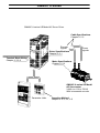
GUÍA RÁPIDA DE
TARJETAS OPCIONALES
DEL CQM1H
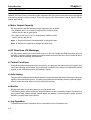
ESTE MANUAL CONTIENE:
1 INTRODUCCIÓN
2 CQM1H-CTB41
3 CQM1H-PLB21
4 CQM1H-ABB21
5 CQM1H-AVB41
6 CQM1H-MAB42
7 CQM1H-SCB41
OMRON ELECTRONICS, S.A.
GR CQM1H MODULOS CPU.DOC
Pag. 1
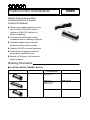
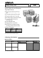
1 Introducción
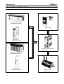
TARJETAS OPCIONALES DEL CQM1H
1 Introducción
En esta guía rápida se van a tratar las diferentes Tarjetas Opcionales que
existen para el CQM1H, su conexión, funcionamiento y modo de operación.
Las tarjetas opcionales que se tienen son las siguientes:
-
CQM1H-CTB41: Tarjeta de Contador de Alta Velocidad.
CQM1H-PLB21: Tarjeta de E/S de Pulsos.
CQM1H-ABB21: Tarjeta de Encoder Absoluto.
CQM1H-AVB41: Tarjeta de Selectores Analógicos.
CQM1H-MAB42: Tarjeta de E/S Analógicas.
CQM1H-SCB41: Tarjeta Serie de Comunicaciones (Comboard).
Las tarjetas opcionales sólo se pueden utilizar en el CQM1H-CPU51 y en el
CQM1H-CPU61.
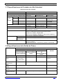
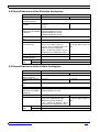
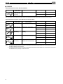
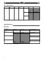
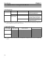
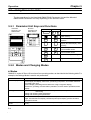
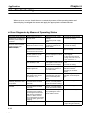
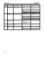
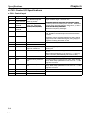
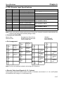
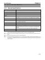
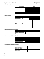
Nombre
Especificaciones
Tarjeta de Contador Entradas de Pulsos (contador de alta
de Alta Velocidad
velocidad): 4 puntos (50KHz/500KHz
seleccionable)
Salidas Externas: 4 puntos
Tarjeta de E/S de
Entradas de Pulsos (Contador de Alta
Pulsos
Velocidad): 2 puntos (de una fase: 50
KHz, diferencia de fase: 25 KHz)
Salida de Pulsos: 2 puntos (50 KHz)
Tarjeta de Encoder Entradas de Encoder (Código Binario
Absoluto
Gray): 2 puntos (4 KHz)
Tarjeta de
Selecciones Analógicas
Selectores
(potenciómetros): 4 puntos
Analógicos
Tarjeta de E/S
Cuatro Entradas: 0 a 5V, 0 a 10V, -10 a
Analógicas
+10V, 0 a 20 mA
Dos Salidas: 0 a 20 mA, -10 a +10V
Tarjeta de
Un Puerto RS-232C y un puerto RSComunicaciones
422A/485
Serie
OMRON ELECTRONICS, S.A.
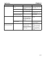
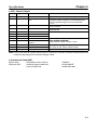
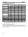
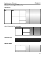
Referencia
Montaje
CQM1H-CTB41
Hueco 1
(Izquierda)
SI
Hueco 2
(Derecha)
SI
CQM1H-PLB21
NO
SI
CQM1H-ABB21
NO
SI
CQM1H-AVB41
CQM1H-MAB42
SI, en cualquiera de los
dos, pero NO EN LOS
DOS A LA VEZ
NO
SI
CQM1H-SCB41
SI
GR CQM1H MODULOS CPU.DOC
NO
Pag. 2
2 CQM1H-CTB41
TARJETAS OPCIONALES DEL CQM1H
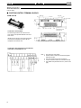
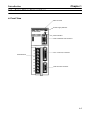
2 CQM1H-CTB41
Es una tarjeta de Contador de Alta Velocidad que tiene 4 Entradas de Pulsos
y 4 Salidas Externas como Resultado de la Comparación.
Tarjeta de Contador de Alta Velocidad
Tarjeta de Contador de Alta Velocidad
Encoders Incrementales
(8 Máximo)
2.1 Funciones
Entradas de Pulsos 1 a 4 de Contador de Alta Velocidad
La CQM1H-CTB41 es capaz de contar pulsos desde 50 a 500 KHz a través
de los puertos 1 a 4, y desarrollar tareas en función del número de pulsos
contados. Los 4 puertos se pueden utilizar independientemente.
Modos de Entrada
Se dispone de 3 modos de entrada:
-
Modo de Fase Diferencial (1x/2x/4x)
Modo Adelante/Atrás
Modo de Pulso y Dirección
Operación de Comparación
Cuando el PV (Valor Presente) del Contador de Alta Velocidad coincide con
un valor objeto o está dentro de un rango de comparación de los
programados, dicho resultado se muestra en los bits internos y externos de
salida.
OMRON ELECTRONICS, S.A.
GR CQM1H MODULOS CPU.DOC
Pag. 3
2 CQM1H-CTB41
TARJETAS OPCIONALES DEL CQM1H
Salidas Externas
Se puede producir la activación de hasta 4 salidas externas cuando el PV del
contador coincide con uno de los valores objeto o está dentro de uno de los
rangos de comparación.
Nota: La Tarjeta de Contador de Alta Velocidad no viene provista de
Interrupciones de Contador de Alta Velocidad. Simplemente compara el PV
del contador con valores objeto o rangos de comparación, y activa un bit de
salida interno o externo.
2.2 Slots que se pueden Utilizar
La Tarjeta de Contador de Alta Velocidad se puede instalar en el slot 1 (slot
izquierdo) o en el slot 2 (slot derecho) del CQM1H-CPU51/61. Ambos slots
pueden estar ocupados por una de estas tarjetas al mismo tiempo (por tanto
se pueden tener montadas dos tarjetas de este tipo en una sola CPU).
2.3 Especificaciones
Instrucciones
Se utilizan las instrucciones: CTBL(63), INI(61) y PRV(62).
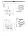
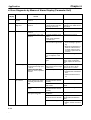
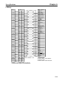
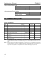
Relación de Bits de Control, Flags, e Información de Estado
Palabra
Slot 1
Slot 2
IR 200
IR 232
IR 201
IR 233
IR 202
IR 234
IR 203
IR 235
IR 204
IR 236
IR 205
IR 237
IR 206
IR 238
IR 207
IR 239
IR 208:
IR 240:
Contador 1 Contador 1
IR 241:
IR 209:
Contador 2 Contador 2
IR 242:
IR 210:
Contador 3 Contador 3
IR 243:
IR 211:
Contador 4 Contador 4
Bits
Nombre
Función
00 a 15
00 a 15
00 a 15
00 a 15
00 a 15
00 a 15
00 a 15
00 a 15
00 a 07
Contador 1 PV (4 dígitos de menor peso)
PV (4 dígitos de mayor peso)
Contador 2 PV (4 dígitos de menor peso)
PV (4 dígitos de mayor peso)
Contador 3 PV (4 dígitos de menor peso)
PV (4 dígitos de mayor peso)
Contador 4 PV (4 dígitos de menor peso)
PV (4 dígitos de mayor peso)
Resultado de la Comparación: Salidas
Internas. Bits 00 a 07
El PV del Contador de Alta
Velocidad de cada puerto se
almacena después de cada
ciclo.
Nota: la forma de almacenar
el PV (en Hex o en BCD) se
puede especificar en el
Setup (DM6602 a DM6611).
Contiene el bit especificado
por el operando de CTBL(63)
cuando se cumple una
condición
08 a 11 Resultado de la Comparación: Bits para las Contiene el bit especificado
Salidas Externas 1 a 4
por el operando de CTBL(63)
cuando se cumple una
condición
12
Flag de Operación de Cuenta
0: Parado
1: Operando
13
Flag de Comparación
Indica si una comparación
está o no en progreso:
0: Parado
1:Operando
14
Flag de Overflow/Underflow del PV
Indica si se ha producido o
no un Overflow o Underflow:
0: Normal
1: Oveflow o Underflow
15
Flag de Error del SV
0: Normal
1: Error de Configuración
OMRON ELECTRONICS, S.A.
GR CQM1H MODULOS CPU.DOC
Pag. 4
2 CQM1H-CTB41
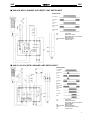
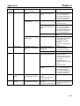
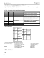
Palabra
Slot 1
Slot 2
IR 212
AR 05
TARJETAS OPCIONALES DEL CQM1H
Bits
00
01
02
03
Bit de Reset del Contador 1
Bit de Reset del Contador 2
Bit de Reset del Contador 3
Bit de Reset del Contador 4
08
Bit de Comienzo de Comparación del
Contador 1
Bit de Comienzo de Comparación del
Contador 2
Bit de Comienzo de Comparación del
Contador 3
Bit de Comienzo de Comparación del
Contador 4
Bit de Stop del Contador 1
Bit de Stop del Contador 2
Bit de Stop del Contador 3
Bit de Stop del Contador 4
Bit para Forzar a Set la Salida Externa 1
Bit para Forzar a Set la Salida Externa 2
Bit para Forzar a Set la Salida Externa 3
Bit para Forzar a Set la Salida Externa 4
Bit para Habilitar el Forzado de Salidas
Externas
09
10
11
IR 213
AR 06
Nombre
12
13
14
15
00
01
02
03
04
SR 254
15
AR 04
00 a 07 Código de Error de la Tarjeta Opcional del
Slot 1
08 a 15 Código de Error de la Tarjeta Opcional del
Slot 2
OMRON ELECTRONICS, S.A.
Flag de Error de la Tarjeta Opcional
GR CQM1H MODULOS CPU.DOC
Función
Reset por Fase Z y Software
0: No Reset con Fase Z
1: Reset con Fase Z
Reset por Software
0: No Reset
0 1: Reset
0 1: Comienzo de la
Comparación
1 0: Paro de la
Comparación
0: Operación Continua
1: Paro de Operación
0: No afecta el Estado de la
Salida
1: Fuerza la Salida a ON
0: Deshabilitado el Forzado
de las Salidas 1 a 4
1: Habilitado el Forzado de
las Salidas 1 a 4
0: No hay Error
1: Error
Se pone a ON cuando se
produce un Error en la
Tarjeta Opcional montada en
el Slot 1 ó 2.
00 Hex: Normal
01 ó 02 Hex: Error Hardware
03 Hex: Error en el Setup
Pag. 5
2 CQM1H-CTB41
TARJETAS OPCIONALES DEL CQM1H
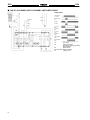
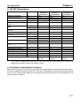
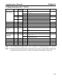
Relación de la Configuración del Setup
Palabra
Slot 2
Slot 1
DM 6602
DM 6611
DM 6640
DM 6643
DM 6641
DM 6644
DM 6641
DM 6644
Bits
Función
Cuando se Lee la
Configuración
00 a 03 Formato en el que se almacena el PV de los
Contadores de 1 a 4.
0: 8 Dígitos Hexadecimal
1: 8 Dígitos BCD
04 a 07 No utilizado
08 a 11 Configuración de las Salidas Externas 1 a 4
0: PNP
1: NPN
12 a 15 No Utilizado
00 a 03 Modo de Entrada del Contador de Alta Velocidad 1
0 Hex: Entrada en Fase Diferencial 1x
1 Hex: Entrada en Fase Diferencial 2x
2 Hex: Entrada en Fase Diferencial 4x
3 Hex: Entrada en Pulso Adelante/Atrás
4 Hex: Entrada en Pulso y Dirección
04 a 07 Frecuencia de Cuenta, Modo de Rango Numérico y
Método de Reset del Contador de Alta Velocidad 1.
Referido a la siguiente tabla de más abajo.
08 a 11 Modo de Entrada del Contador de Alta Velocidad 2
(Referido a la explicación dada más arriba para el
Contador 1)
12 a 15 Frecuencia de Cuenta, Modo de Rango Numérico y
Método de Reset del Contador de Alta Velocidad 2.
(Referido a la siguiente tabla de más abajo)
00 a 03 Modo de Entrada del Contador de Alta Velocidad 3
(Referido a la explicación dada más arriba para el
Contador 1)
04 a 07 Frecuencia de Cuenta, Modo de Rango Numérico y
Método de Reset del Contador de Alta Velocidad 3.
(Referido a la siguiente tabla de más abajo)
08 a 11 Modo de Entrada del Contador de Alta Velocidad 4
(Referido a la explicación dada más arriba para el
Contador 1)
12 a 15 Frecuencia de Cuenta, Modo de Rango Numérico y
Método de Reset del Contador de Alta Velocidad 4.
(Referido a la siguiente tabla de más abajo)
Cuando se da la
alimentación
Cuando comienza
la operación
Cuando comienza
la operación
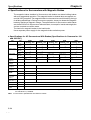
Frecuencia de Cuenta, Modo de Rango Numérico y Método de Reset de
los Contadores de Alta Velocidad
Valor
0 Hex
1 Hex
2 Hex
3 Hex
4 Hex
5 Hex
6 Hex
7 Hex
Frecuencia de Cuenta
50 KHz
Modo de Rango Numérico
Modo Lineal
Modo Circular
500 KHz
OMRON ELECTRONICS, S.A.
Modo Lineal
Modo Circular
GR CQM1H MODULOS CPU.DOC
Método de Reset
Fase Z + Software
Software
Fase Z + Software
Software
Fase Z + Software
Software
Fase Z + Software
Software
Pag. 6
2 CQM1H-CTB41
TARJETAS OPCIONALES DEL CQM1H
2.4 Contadores de Alta Velocidad de 1 a 4
Señales de Entrada y Modos de Entrada
- Modo de Fase Diferencial (Velocidad de Cuenta: 25 KHz ó 250 KHz)
- Modo Adelante/Atrás (Velocidad de Cuenta: 50 KHz ó 500 KHz)
- Modo Pulso/Dirección (Velocidad de Cuenta: 50 KHz ó 500 KHz)
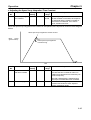
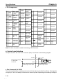
Rangos Numéricos
- Modo Circular: de 00000000 a 08388607 en BCD ó de 00000000 a
07FFFFFF en Hex.
- Modo Lineal: de –8388608 a 8388607 en BCD ó de F8000000 a
07FFFFFF en Hex.
Modo Circular
Modo Lineal
Máx. Valor de Cuenta
Decrementa
Incrementa
Métodos de Reset
- Reset de Fase Z + Software.
- Reset por Software.
Métodos de Chequeo para las Interrupciones de Contador de Alta
Velocidad
- Método por Valores Coincidentes (hasta 48 valores objeto).
- Método por Rangos de Comparación (hasta 16 rangos).
OMRON ELECTRONICS, S.A.
GR CQM1H MODULOS CPU.DOC
Pag. 7
2 CQM1H-CTB41
TARJETAS OPCIONALES DEL CQM1H
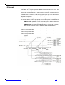
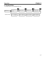
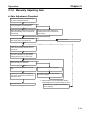
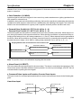
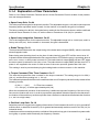
Procedimiento para Utilizar los Contadores de Alta Velocidad
Determinar el Rango de Cuenta,
Modo de Entrada, Método de
Reset, Modo de Rango Numérico,
formato en el que se almacena el
PV del contador, y el método de
salidas externas.
Rango de Cuenta: 50 KHz/500 KHz
Modo de Entrada: Fase Diferencial,
Pulso/Dirección, Adelante/Atrás.
Método de Reset: Fase Z+Software; Software.
Modo de Rango Numérico: Modo Circular o
Modo Lineal.
Formato del PV: 8 Dígitos BCD u 8 Dígitos
Hexadecimal.
Método de las Salidas Externas: NPN o PNP.
Configurar la Tensión de Entrada
(switches de la Tarjeta)
Montar la Tarjeta y Cablear las
Entradas
Setup del PLC
(Slot 1: DM6602, DM6640,
DM6641)
(Slot 2: DM6611, DM6643,
DM6644)
Rango de Cuenta: 50 KHz/500 KHz
Modo de Entrada: Fase Diferencial,
Adelante/Atrás, Pulso/Dirección
Método de Reset: Fase Z+Software, Software
Modo de Rango Numérico: Modo Circular o
Modo Lineal.
Formato del PV: 8 Dígitos BCD u 8 Dígitos
Hexadecimal.
Método de las Salidas Externas: NPN o
PNP.
Determinar el Método de Chequeo
de Cuenta (comparación) y bits
internos/externos de salida.
Programa Ladder del PLC
OMRON ELECTRONICS, S.A.
GR CQM1H MODULOS CPU.DOC
Métodos de Comparación: por Valores
Coincidentes o por Rangos de Comparación.
Bits de Salida cuando se cumplen las
condiciones de comparación: Internos y
Externos
TABLA DE COMPARACIÓN DE
REGISTROS (CTBL(63)): Especificación del
Puerto, Registro de la Tabla de Comparación,
Comienzo de la Comparación.
MODO DE CONTROL (INI(61)):
Especificación del Puerto, cambio del PV,
Comienzo de la Comparación.
LECTURA DEL PV (PRV(62)):
Lectura del PV del Contador de Alta
Velocidad y el Estado de la Comparación.
Pag. 8
2 CQM1H-CTB41
TARJETAS OPCIONALES DEL CQM1H
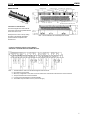
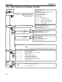
Switches para el Nivel de Tensión de las Entradas
Contador 1 Contador 2 Contador 3 Contador 4 Estado
SW6-2
SW3-1
SW3-2
ON
SW6-1
OFF
SW5-1
SW5-2
SW2-1
SW2-2
ON
OFF
SW4-1
SW4-2
SW1-1
SW1-2
ON
OFF
Configuración
Entrada del Contador:
Line Driver
Entrada de Tensión A
24 VDC (defecto)
Entrada del Contador:
Line driver
Entrada de Tensión B
24 VDC (defecto)
Entrada del Contador:
Line Driver
Entrada de Tensión Z
24 VDC (defecto)
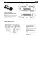
Pineado de los Conectores CN1 y CN2
Situación de los Pines
OMRON ELECTRONICS, S.A.
Nº de Pin
1
2
3
4
5
6
7
8
9
Nombre
2OUT
1OUT
1Z1Z+
1B1B+
1A1A+
+DC
10
11
12
13
14
15
2Z2Z+
2B2B+
2A2A+
Función
Salida Externa 2
Salida Externa 1
Entrada de Contador 1: ZEntrada de Contador 1: Z+
Entrada de Contador 1: BEntrada de Contador 1: B+
Entrada de Contador 1: AEntrada de Contador 1: A+
Alimentación para las Salidas Externas 1 a 4.
5 a 24 VDC
Entrada de Contador 2: ZEntrada de Contador 2: Z+
Entrada de Contador 2: BEntrada de Contador 2: B+
Entrada de Contador 2: AEntrada de Contador 2: A+
GR CQM1H MODULOS CPU.DOC
Pag. 9
2 CQM1H-CTB41
Situación de los Pines
TARJETAS OPCIONALES DEL CQM1H
Nº de Pin
1
2
3
4
5
6
7
8
9
10
11
12
13
14
15
Nombre
3Z3Z+
3B3B+
3A3A+
4OUT
3OUT
4Z4Z+
4B4B+
4A4A+
-DC
Función
Entrada de Contador 3: ZEntrada de Contador 3: Z+
Entrada de Contador 3: BEntrada de Contador 3: B+
Entrada de Contador 3: AEntrada de Contador 3: A+
Salida Externa 4
Salida Externa 3
Entrada de Contador 4: ZEntrada de Contador 4: Z+
Entrada de Contador 4: BEntrada de Contador 4: B+
Entrada de Contador 4: AEntrada de Contador 4: A+
Alimentación para las Salidas Externas 1 a 4.
0V
Conexión de un Encoder de Colector Abierto de 24 VDC
Conexión de un Encoder con Salida Line Driver
OMRON ELECTRONICS, S.A.
GR CQM1H MODULOS CPU.DOC
Pag. 10
2 CQM1H-CTB41
TARJETAS OPCIONALES DEL CQM1H
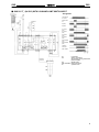
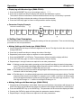
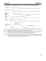
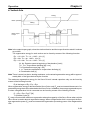
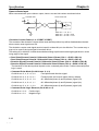
2.5 Ejemplo
El siguiente ejemplo muestra como se puede utilizar el Contador de Alta
Velocidad 1 en la Tarjeta Opcional CQM1H-CTB41 montada en el Slot 2. Se
va a realizar una comparación por valores coincidentes para que se pongan a
ON los bits correspondientes de salida internos y externos, en función del PV
del contador.
El Bit de Reset se mantiene a ON en el programa para que el PV del contador
se resetee con la señal de Fase Z, después de que se alcance el último valor
objeto de comparación.
Antes de ejecutar el programa, se tiene que configurar el CQM1H tal y como
se muestra debajo, teniendo que apagar y encender o pasar de PROGRAM a
MONITOR el PLC, para que se habilite la nueva configuración en el DM6611.
DM 6611: 0001 (Salidas 1 a 4 en modo PNP, y el PV de los contadores
1 a 4 se almacenará en 8 Dígitos BCD)
DM 6643: 0003 (Contador de Alta Velocidad 1: Frecuencia de 50KHz;
Modo Lineal; Reset por Fase Z + Software; Modo Adelante/Atrás).
Cuando el PV alcance el valor de 2500, IR 05000 se pondrá a ON y la Salida
Externa 1 se pondrá a ON.
Cuando el PV alcance el valor de 7500, IR 05001 se pondrá a ON y la Salida
Externa 2 se pondrá a ON.
Cuando el PV alcance el valor de 10000, IR 05002 se pondrá a ON y la Salida
Externa 3 se pondrá a ON.
OMRON ELECTRONICS, S.A.
GR CQM1H MODULOS CPU.DOC
Pag. 11
2 CQM1H-CTB41
TARJETAS OPCIONALES DEL CQM1H
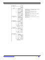
DM 0000: 0003 -- Tres Condiciones de Comparación
DM 0001: 2500 -- Valor Objeto 1: 2500
DM 0002: 0000
DM 0003: 0100 – Bit de Salida Externa 1
DM 0004: 7500 – Valor Objeto 2: 7500
DM 0005: 0000
DM 0006: 0201 – Bit de Salida Externa 2 y Bit de
Salida Interna 0
DM 0007: 0000 – Valor Objeto 3: 10000
DM 0008: 0001
DM 0009: 0402 – Bit de Salida Externa 3 y Bit de
Salida Interna 1
OMRON ELECTRONICS, S.A.
GR CQM1H MODULOS CPU.DOC
Pag. 12
3 CQM1H-PLB21
TARJETAS OPCIONALES DEL CQM1H
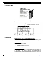
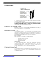
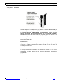
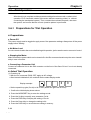
3 CQM1H-PLB21
La Tarjeta Opcional de E/S de Pulsos CQM1H-PLB21 dispone de 2 Entradas
de Pulsos y 2 Salidas de Pulsos.
La Tarjeta Opcional CQM1H-PLB21 es exactamente igual que los puertos
de Entrada/Salida (CN1 y CN2) de pulsos que incorporaba el CQM1CPU43. Se comporta del mismo modo, se programa y pone en marcha de la
misma forma, y tienen las mismas características.
3.1 Slot en el que se puede montar
Esta tarjeta sólo se puede montar en el Slot 2 (slot derecho) de la CPU, por
tanto sólo se puede montar 1 Tarjeta por CPU.
3.2 Entradas de Pulsos 1 y 2
Las Entradas de Pulsos 1 y 2 se pueden utilizar como Contadores de Alta
Velocidad para contar entradas de pulsos de hasta 50 KHz (para señales de
fase simple) ó 25 KHz (para fase diferencial). Los procesos de interrupción se
pueden desarrollar teniendo en cuenta el PV de los contadores.
Modo de Entrada
Están disponibles los tres modos de entrada siguientes:
•
•
•
Modo de Fase Diferencial (4x)
Modo Pulso y Dirección
Modo Adelante/Atrás
Interrupciones
La tarjeta CQM1H-PLB21 puede ejecutar una subrutina de interrupción
cuando el valor del contador de alta velocidad coincide con un valor objeto
(previamente programado), o una subrutina de interrupción cuando el PV del
contador cae dentro de un rango de comparación especificado.
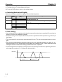
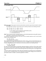
3.3 Salida de Pulsos 1 y 2
La tarjeta opcional CQM1H-PLB21 dispone de 2 salidas de pulsos entre 10 Hz
y 50 KHz a través de los puertos 1 y 2. En ambos se puede configurar un ciclo
de trabajo fijo o variable.
OMRON ELECTRONICS, S.A.
GR CQM1H MODULOS CPU.DOC
Pag. 13
3 CQM1H-PLB21
TARJETAS OPCIONALES DEL CQM1H
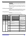
3.4 Puertos 1 y 2
A través de estos puertos se pueden utilizar simultáneamente las 2 Entradas
de Pulsos (Contador de Alta Velocidad) y las 2 Salidas de Pulsos.
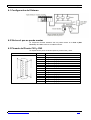
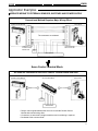
3.5 Configuración del Sistema
Tarjeta de E/S de Pulsos
Entrada de Pulsos 2
Entrada de Pulsos 1
Encoder Incrementnal
Encoder Incremental
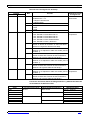
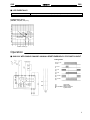
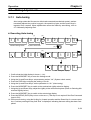
3.6 Pineado del Puerto CN1 y CN2
La disposición de pines es idéntica para los puertos CN1 y CN2:
Situación de los Pines
Nº de Pin
1
2
3
4
5
6
7
8
9
10
11
12
13
14
15
OMRON ELECTRONICS, S.A.
Nombre
Común de Entrada
Entrada de Pulsos Z: 24 VDC
Entrada de Encoder A: 24 VDC
Entrada de Encoder B: 24 VDC
Salida de Pulsos CCW
Salida de Pulsos CW/Salida PWM(--)
Fuente de Alimentación de 5 VDC para la
Salida
Fuente de Alimentación de 5 VDC para la
Salida
Entrada de Pulsos Z: 12 VDC
Entrada de Encoder A: 12 VDC
Entrada de Encoder B: 12 VDC
Común de Salida (0 V)
Salida de Pulsos CCW (con resistencia de
1.6K
Salida de Pulsos CW/Salida PWM(--) (con
resistencia de 1.6K
Fuente de Alimentación para la Salida
GR CQM1H MODULOS CPU.DOC
Función
Entrada de
Pulsos
Salida de
Pulsos
Entrada de
Pulsos
Salida de
Pulsos
Pag. 14
3 CQM1H-PLB21
TARJETAS OPCIONALES DEL CQM1H
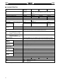
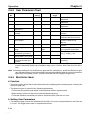
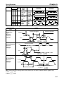
3.7 Especificaciones del Contador de Alta Velocidad
Especificaciones del Contador
Elemento
Número de Contadores
Modos de Entrada (Configurables
para cada puerto en el Setup del PLC)
Número Puerto 1
Puerto 2
del Pin
3/10
3/10
de
Entrada 4/11
4/11
2/9
Método de Entrada
2/9
Frecuencia de Cuenta
Valor de Cuenta
PV del Contador
Método de Control
Valor Objeto
Rango de
Comparación
Método de Reset del Contador
Especificación
2 Contadores (puertos)
Entrada en Fase
Entrada de
Entrada de Pulso
Diferencial
Pulso/Dirección
Adelante/Atrás
--Entrada de Fase A Entrada de Dirección Entrada de Pulsos
Decremental
Entrada de Fase B Entrada de Pulsos
Entrada de Pulsos
Incremental
Entrada de Fase Z Entrada de Reset
Entrada de Reset
Diferencia de Fase Pulsos de Fase
Pulsos de Fase
de 4 (Fijo)
Simple + Dirección
Simple x 2
25 KHz
50 KHz
50 KHz
Modo Lineal: -8388608 a 8388607
Modo Circular: 0 a 64999
Puerto 1: IR 233 (mayor peso) e IR 232 (menor peso)
Puerto 2: IR 235 (mayor peso) e IR 234 (menor peso)
Formato de los Datos: 8 Dígitos BCD
Modo Lineal: F8388608 a 8388607 (F para valores negativos).
Modo Circular: 00000000 a 00064999.
Hasta 48 valores objeto e interrupciones
Hasta 8 Límites Superiores, Inferiores e Interrupciones
Señal de la Fase Z + Reset de Software
Reset por Software
Bits de Reset: (Puerto 1: SR 252.01) y (Puerto 2: SR 252.02)
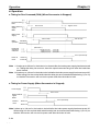
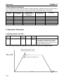
3.8 Especificaciones de la Salida de Pulsos
Elemento
Instrucción
Frecuencia de
Salida
Saltos de
Frecuencia de
Salida
Factor de Ciclo de
Trabajo
Número de Pulsos
de Salida
Rango de
Aceleración/Deceler
ación
Especificaciones
Ciclo de Trabajo Fijo
Ciclo de Trabajo
Variable
Sin
Mismo Rango de Rangos Separados
Aceleración/Decele Aceleración/Decele
de
ración Trapezoidal
ración
Aceleración/Decele
ración
PULS(65)/SPED(64) PLS2(--)
PULS(65)/ACC(--)
PWM(--)
10 Hz a 50 KHz
0 Hz a 50 KHz
100 Hz a 50 KHz
91.6 Hz, 1.5 KHz,
10 Hz a 20 KHz
5.9 KHz
para motor paso a
paso
1 o 10 Hz
10 Hz
---
50 % Fijo
1 a 99%
1 a 16777215
---
---
OMRON ELECTRONICS, S.A.
10 Hz a 2 KHz (cada 4.08 ms)
GR CQM1H MODULOS CPU.DOC
---
Pag. 15
4 CQM1H-ABB21
TARJETAS OPCIONALES DEL CQM1H
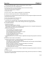
4 CQM1H-ABB21
Se trata de una Tarjeta Opcional de Encoder Absoluto que cuenta dos
entradas de pulsos en código binario gray desde un encoder absoluto (ABS) a
través de los puertos 1 y 2 a un máximo de 4KHz de frecuencia.
La Tarjeta Opcional CQM1H-ABB21 es exactamente igual que los
puertos de Entrada de Encoder Absoluto que incorporaba el CQM1CPU44. Se comporta del mismo modo, se programa y pone en marcha de la
misma forma, y tienen las mismas características.
Modos de Operación
Modo BCD y Modo 360º.
Resoluciones
Se puede configurar una de las siguientes: 8 bits (0 a 255), 10 bits (0 a 1023),
o 12 bits (0 a 4095). La resolución debería coincidir con la que tenga el
encoder que se conecte.
Interrupciones
Se puede ejecutar una subrutina de interrupción cuando el PV (Valor
Presente) del contador absoluto de alta velocidad coincida con un valor objeto
especificado o caiga dentro de uno de los rangos de comparación
programados.
OMRON ELECTRONICS, S.A.
GR CQM1H MODULOS CPU.DOC
Pag. 16
4 CQM1H-ABB21
TARJETAS OPCIONALES DEL CQM1H
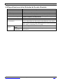
4.1 Configuración del Sistema
4.2 Slot en el que se puede montar
La Tarjeta de Encoder Absoluto sólo se puede montar en el Slot 2 (Slot
Derecho) del CQM1H-CPU51 ó CQM1H-CPU61.
4.3 Pineado del Puerto CN1 y CN2
La disposición de pines es idéntica para los puertos CN1 y CN2:
Situación de los Pines
OMRON ELECTRONICS, S.A.
Nº de Pin
1
2
3
4
5
6
7
8
9
10
11
12
13
14
15
Nombre
Común de Entrada
11
Bit 2 del código gray binario del encoder
9
Bit 2 del código gray binario del encoder
7
Bit 2 del código gray binario del encoder
5
Bit 2 del código gray binario del encoder
3
Bit 2 del código gray binario del encoder
1
Bit 2 del código gray binario del encoder
No utilizado
Común de Entrada
10
Bit 2 del código gray binario del encoder
8
Bit 2 del código gray binario del encoder
6
Bit 2 del código gray binario del encoder
4
Bit 2 del código gray binario del encoder
2
Bit 2 del código gray binario del encoder
0
Bit 2 del código gray binario del encoder
GR CQM1H MODULOS CPU.DOC
Pag. 17
4 CQM1H-ABB21
TARJETAS OPCIONALES DEL CQM1H
4.4 Especificaciones de las Entradas de Encoder Absoluto
Elemento
Número de Puntos de Entrada
Código de Entrada
Modos de Operación
Resoluciones
Compensación de Origen
Especificaciones
2 puntos
Código Binario Gray
Modo BCD o Modo 360º (Configurado en el Setup del PLC)
8 bit, 10 bit, o 12 bit (Configurado en el Setup del PLC)
Si (se puede designar la actual posición como origen), la compensación
se puede configurar en el Setup del PLC
Frecuencia de cuenta
4 KHz máx.
Almacenamiento del PV de Puerto 1: IR233 (parte de mayor peso) e IR232 (parte de menor peso)
los contadores
Puerto 2: IR235 (parte de mayor peso) e IR234 (parte de menor peso)
Los datos se almacenan como 4 dígitos en BCD.
Nota: el rango de valores queda determinado por el modo de operación
(BCD o 360º) y la resolución (8, 10 ó 12 bits).
Métodos de Por Valor
Se pueden registrar hasta 48 valores objeto e interrupciones
Control
Objeto
Por Rangos de Se pueden almacenar hasta 8 límites superiores, límites inferiores e
Comparación
interrupciones
OMRON ELECTRONICS, S.A.
GR CQM1H MODULOS CPU.DOC
Pag. 18
5 CQM1H-AVB41
TARJETAS OPCIONALES DEL CQM1H
5 CQM1H-AVB41
Se trata de una Tarjeta Opcional de Selectores Analógicos.
La Tarjeta Opcional CQM1H-AVB41 es exactamente igual que los
selectores que incorporaba el CQM1-CPU42. Se comporta del mismo
modo, se programa y pone en marcha de la misma forma, y tienen las mismas
características.
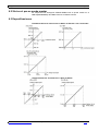
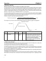
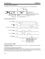
5.1 Función
Cada uno de los valores que representan la posición en la que se encuentran
los selectores analógicos (que son resistores variables) localizados en el
frente de la tarjeta, se almacenan como 4 dígitos en BCD entre 0000 y 0200
de IR220 a IR223 para los selectores 0 a 3 respectivamente.
A modo de ejemplo, el operador puede utilizar un selector analógico para
variar el tiempo de configuración de un temporizador, mediante un
destornillador, para manipular el selector analógico seleccionado para dicha
función. Así el siguiente ejemplo muestra los 4 dígitos en BCD de 0000 a 0200
en el canal IR220 para poder variar el tiempo del temporizador TIM000.
El valor de configuración de TIM000 se
configura externamente con IR220. (El
temporizador se ejecuta utilizando el valor
configurado a través del selector analógico 0.)
OMRON ELECTRONICS, S.A.
GR CQM1H MODULOS CPU.DOC
Pag. 19
5 CQM1H-AVB41
TARJETAS OPCIONALES DEL CQM1H
5.2 Slot en el que se puede montar
La tarjeta de Selectores Analógicos se puede instalar o en el slot 1(slot
izquierdo) o en el slot 2 (slot derecho) del CQM1H-CPU51 ó CQM1H-CPU61.
Sin embargo, no se pueden utilizar ambos slots al mismo tiempo con dos
tarjetas de selectores analógicos.
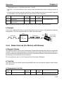
5.3 Nombres y Funciones
Los cuatro controles analógicos de la Tarjeta de Selectores Analógicos están
localizados en el frente de la tarjeta. El frente de la tarjeta no tiene ningún
indicador.
El valor de los canales que representan a cada selector se incrementa o
decrementa girando a derechas o izquierdas los selectores analógicos
respectivamente. Es necesario utilizar un destornillador de estrella.
OMRON ELECTRONICS, S.A.
GR CQM1H MODULOS CPU.DOC
Pag. 20
6 CQM1H-MAB42
TARJETAS OPCIONALES DEL CQM1H
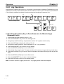
6 CQM1H-MAB42
Se trata de una Tarjeta Opcional de E/S Analógicas que tiene 4 Entradas
Analógicas y 2 Salidas Analógicas.
Los rangos de señal que se pueden utilizar para cada una de las entradas
analógicas son de: –10v a +10v, 0 a 5v, y 0 a 20mA. Se puede configurar el
rango de forma individual para cada punto de entrada. La configuración de los
rangos, para los puntos de entrada, se realiza en el DM6611.
Los rangos de señal que se pueden utilizar para cada una de las salidas
analógicas son de: –10 a +10v y de 0 a 20mA. Se puede configurar el rango
de forma individual para cada punto de salida. La configuración de los rangos
se realiza en el DM6611.
La Tarjeta Opcional CQM1H-MAB42 es exactamente igual que los
puertos de entradas y salidas analógicos que incorporaba el CQM1CPU45. Se comporta del mismo modo, se programa y pone en marcha de la
misma forma, y tienen las mismas características.
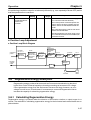
6.1 Configuración del Sistema
Tarjeta de E/S Analógicas
4 Puntos de Entrada Analógica
OMRON ELECTRONICS, S.A.
2 Puntos de Salida Analógica
GR CQM1H MODULOS CPU.DOC
Pag. 21
6 CQM1H-MAB42
TARJETAS OPCIONALES DEL CQM1H
6.2 Slot en el que se puede montar
La Tarjeta de E/S Analógicas CQM1H-MAB42 sólo se puede montar en el
Slot 2 (slot derecho) del CQM1H-CPU51 ó CQM1H-CPU61.
6.3 Especificaciones
Entradas Analógicas: Valores de los Datos de Entrada y los Convertidos
Salidas Analógicas: Configuración y Dato de Salida
OMRON ELECTRONICS, S.A.
GR CQM1H MODULOS CPU.DOC
Pag. 22
6 CQM1H-MAB42
TARJETAS OPCIONALES DEL CQM1H
6.4 Pineado del Puerto CN1 y CN2
CN1: Entradas Analógicas
Situación de los Pines
Nº de Pin
1
2
Nombre
V4+
V4-
3
4
V3+
V3-
5
6
V2+
V2-
7
8
V1+
V1-
9
10
11
12
13
14
15
I4+
NC
I3+
NC
I2+
NC
I1+
Función
Entrada Analógica 4: Entrada de Tensión +
Entrada Analógica 4: común (entrada de
tensión -, entrada de corriente -)
Entrada Analógica 3: Entrada de Tensión +
Entrada Analógica 3: común (entrada de
tensión -, entrada de corriente -)
Entrada Analógica 2: Entrada de Tensión +
Entrada Analógica 2: común (entrada de
tensión -, entrada de corriente -)
Entrada Analógica 1: Entrada de Tensión +
Entrada Analógica 1: común (entrada de
tensión -, entrada de corriente -)
Entrada Analógica 4: entrada de corriente +
No utilizar
Entrada Analógica 3: entrada de corriente +
No utilizar
Entrada Analógica 2: entrada de corriente +
No utilizar
Entrada Analógica 1: entrada de corriente +
CN2: Salidas Analógicas
Situación de los Pines
OMRON ELECTRONICS, S.A.
Nº de Pin
1
2
3
Nombre
NC
NC
I2-
4
V2-
5
6
7
NC
NC
I1-
8
V1-
9
10
11
12
13
14
15
NC
I2+
V2+
NC
NC
I1+
V1+
Función
No utilizado
No utilizado
Salida Analógica 2: común (salida de
corriente -)
Salida Analógica 2: común (salida de
tensión -)
No utilizado
No utilizado
Salida Analógica 1: común (salida de
corriente -)
Salida Analógica 1: común (salida de
tensión -)
No utilizado
Salida Analógica 2: salida de corriente +
Salida Analógica 2: salida de tensión +
No utilizado
No utilizado
Salida Analógica 1: salida de corriente +
Salida Analógica 1: salida de tensión +
GR CQM1H MODULOS CPU.DOC
Pag. 23
6 CQM1H-MAB42
TARJETAS OPCIONALES DEL CQM1H
6.5 Especificaciones de las Entradas Analógicas
Elemento
Señales de Entrada
Número de Puntos de
Entrada Analógica
Rangos de la Señal de
Entrada
Entrada en Tensión
4 Entradas
Especificación
Entrada en Corriente
-10 a 10 V
0 a 10 V
0a5V
Registros en los que se Entrada Analógica 1: IR 232
almacenan las entradas Entrada Analógica 2: IR 233
analógicas
Entrada Analógica 3: IR 234
Entrada Analógica 4: IR 235
Tiempo de Conversión 1.7 ms máx./punto
A/D
Resolución
1/4096
Dato de Salida de la
Dato de 12 bits en Binario
Conversión A/D
-10 a +10 V:F800 a 07FF Hex
0 a 10 V, 0 a 5 V: 0000 a 0FFF Hex
Nota las tensiones negativas
(-10V tensión de entrada < 0V) se
almacenan en complemento a dos.
Impedancia de Entrada 1 M típico
Máximo Rango de
±15 V
Entrada Absoluto
Precisión
±0.5% del FS
23±2ºC
total
0 a 55ºC
±1.0% del FS
0 a 20 mA
Dato de 12 bits en Binario
0 a 20 mA: 0000 a 0FFF en
Hex
250 típico
±30 mA
6.6 Especificaciones de las Salidas Analógicas
Elemento
Señales de Salida
Número de Puntos de
Salida Analógica
Rangos de la Señal de
Salida
Tiempo de Conversión
D/A
Resolución
Registros en los que se
almacenan las salidas
analógicas
Impedancia de Salida
Configuración del dato
Precisión
Total
OMRON ELECTRONICS, S.A.
23±2ºC
0 a 55ºC
Salida en Tensión
2 salidas
Especificaciones
Salida en Corriente
-10 a 10 V
0 a 20 mA
1.7 ms máx./2 puntos
1/4095
Salida Analógica 1: IR 236
Salida Analógica 2: IR 237
1/2047
2 K mín.
Dato de 12 bits en Binario
-10 a +10 V: F800 a 07FF Hex
Nota las tensiones negativas
(-10V tensión de entrada < 0V) se
almacenan en complemento a dos.
0 a 55ºC
±1.0% del FS
350 máx.
Dato de 11 bits en Binario
0 a 20 mA: 0000 a 07FF en
Hex
GR CQM1H MODULOS CPU.DOC
Pag. 24
7 CQM1H-SCB41
TARJETAS OPCIONALES DEL CQM1H
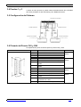
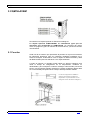
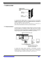
7 CQM1H-SCB41
La Tarjeta Opcional CQM1H-SCB41 se trata de otra de las nuevas tarjetas
opcionales que se pueden utilizar con el CQM1H-CPU51/61, que puede ser
instalada, únicamente, en el slot 1 (slot izquierdo) de la CPU. Esta tarjeta no
puede ser instalada en el slot 2 (slot derecho).
Esta tarjeta tiene dos puertos serie de comunicaciones, de esta forma se
puede incrementar fácilmente el número de puertos del CQM1H.
7.1 Características
La tarjeta serie de comunicaciones permite aumentar el número de puertos
serie del CQM1H sin necesidad de utilizar ningún slot de E/S. Permite
programar Macros de Protocolo (algo que no es posible realizar en los puertos
de la CPU), por tanto, proporciona la posibilidad de conectar fácilmente
cualquier dispositivo de propósito general que tenga un puerto serie.
La tarjeta tiene ambos puertos: RS-232C y RS-422A/485. El puerto
RS422A/485 da la posibilidad de realizar conexiones 1:N con dispositivos de
propósito general sin necesidad de utilizar ningún conversor. Las conexiones
1:N se pueden utilizar con Macros de Protocolo o con NT-Link 1:N.
OMRON ELECTRONICS, S.A.
GR CQM1H MODULOS CPU.DOC
Pag. 25
7 CQM1H-SCB41
TARJETAS OPCIONALES DEL CQM1H
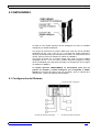
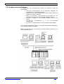
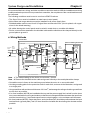
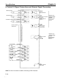
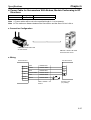
7.2 Configuración del Sistema
La Tarjeta Serie de Comunicaciones soporta los siguientes modos de
comunicación:
• Host Link: comunicaciones con un ordenador, dispositivo de
programación o Terminal Programable.
• Protocolo Libre: comunicaciones sin protocolo (TXD y RXD) con
dispositivos externos estándar.
• Macro de Protocolo: comunicaciones de acuerdo con las
especificaciones de comunicaciones del dispositivo externo.
• PC-Link 1:1: enlace 1:1 con un CQM1H, CQM1 u otro PLC de
serie C.
• NT-Link 1:N: comunicaciones 1:1 ó 1:N con terminales
programables.
• NT-Link 1:1: comunicaciones 1:N con terminales programables.
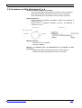
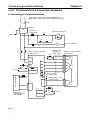
En el siguiente diagrama se puede ver un ejemplo de los distintos dispositivos
que se pueden conectar a la tarjeta.
Nota: Los modos NT-Link 1:1 y NT-Link 1:N utilizan distintos protocolos y no
son compatibles entre sí.
OMRON ELECTRONICS, S.A.
GR CQM1H MODULOS CPU.DOC
Pag. 26
7 CQM1H-SCB41
TARJETAS OPCIONALES DEL CQM1H
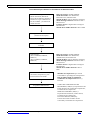
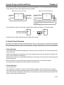
7.3 Macros de Protocolo
Las macros de protocolo proporcionan un sistema para crear protocolos de
comunicaciones de datos, de acuerdo con las especificaciones de
comunicaciones de dispositivos externos con puerto serie (semi-dúplex,
sincronización start-stop). Las macros de protocolo se crean con el Software
de Soporte “CX-Protocol”, para después grabar las macros creadas en la
tarjeta de comunicaciones serie, donde se podrán ejecutar en cualquier
momento utilizando la instrucción PMCR en el programa de diagrama de relés
de la CPU.
Con el CX-Protocol y la tarjeta de comunicaciones serie, se suministran
protocolos estándar para comunicar con dispositivos OMRON, tales como
controladores de temperatura, procesadores inteligentes de señal, lectores de
código de barras y módems. Los protocolos estándar también se pueden
modificar con el CX-Protocol para aplicaciones específicas.
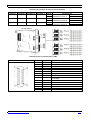
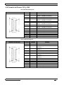
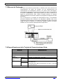
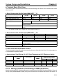
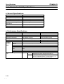
7.4 Especificaciones de la Tarjeta de Comunicaciones Serie
Elemento
Especificaciones
Modelo
CQM1H-SCB41
Clasificación de la Unidad
Tarjeta Opcional de la serie CQM1H
CPUs aplicables
CQM1H-CPU61/51
Huecos de montaje y Número de Se puede montar 1 tarjeta en el hueco 1 (izquierdo)
Tarjetas
Puertos de
Puerto 1
RS-232C: 19.2 Kbps máx., 15 m máx.
Comunicaciones Puerto 2
RS-422A/485: 19.2 Kbps máx., 500 m máx.
Serie
Protocolos
Puerto 1
Cada puerto se puede seleccionar independientemente a
modo Host Link
Puerto 2
, Protocolo Libre, Macro de Protocolo, PC-Link 1:1, NT-Link
1:1 o NT-Link 1:N.
Consumo
200 mA máx.
OMRON ELECTRONICS, S.A.
GR CQM1H MODULOS CPU.DOC
Pag. 27
Table of Contents
Name
Page Number
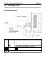
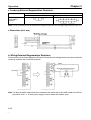
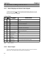
PLC Connections
Cable Solutions for Omron PLCs
Cable Solutions for Multi-Vendor PLCs
i
1
11
15
Reference Information
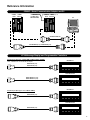
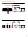
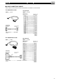
PLC Connections
The following pages illustrate the cabling options for
connecting Omron programmable controllers with
computers, Omron's HMIs, hand-held programmers,
high-density I/O modules and I/O terminal blocks.
Hand-held Programmers and CPM1A, CPM2A, SRM1 Peripheral Port
CPM1A
CPM2A
SRM1
C200H-CN222 (2 m)
C200H-CN422 (4 m)
CQM1-PRO01-E
C200H-PRO27-E
1
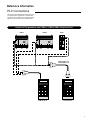
Reference Information
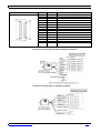
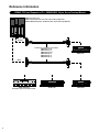
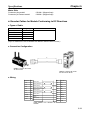
Hand-held Programmers and CQM1H Peripheral Port
CQM1H
CS1W-CN224 (2 m)
CS1W-CN624 (6 m)
CQM1H-PRO01-E
C200H-PRO27-E
CS1W-CN114 (5 cm)
CQM1-PRO01-E
2
CS1W-CN114 (5 cm)
C200H-CN222 (2 m)
C200H-CN422 (4 m)
C200H-PRO27-E
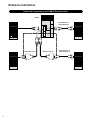
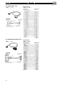
Reference Information
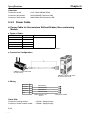
Hand-held Programmer and CPM2C Communication Port
CPM2C
CS1W-CN114 (5 cm)
CQM1H-PRO01-E
CS1W-CN224 (2 m)
CS1W-CN624 (6 m)
CS1W-KS001-E
Key Sheet
(supplied with
CQM1-PRO01-E)
CQM1-PRO01-E
CS1W-KS001-E
Key Sheet
(supplied with
C200H-PRO27-E)
C200H-PRO27-E
3
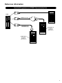
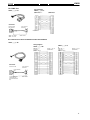
Reference Information
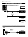
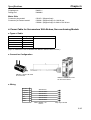
CQM1H and PC
CQM1H
To peripheral port on the CPU:
CS1W-CN226 (2 m), CS1W-CN626 (6 m)
CS1W-CN118 (10 cm)
C200HS-CN220-EU (2 m)
CS1W-CN114 (5 cm)
CQM1-CIF02
PC
To serial port on the CPU or Inner Board:
C200HS-CN220-EU Program Download Cable
C200H-CN320-EU Communication Cable
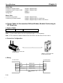
CPM2C and PC
CS1W-CN226 (2 m), CS1W-CN626 (6 m)
CPM2C
CS1W-CN118 (10 cm)
C200HS-CN220-EU (2 m)
CS1W-CN114 (5 cm)
CQM1-CIF02
CPM2C-CN111
(15 cm)
HMI
4
CQM1-PRO01-E, etc.
PC
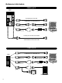
Reference Information
CPM2C + Serial Communication Adapter and PC
CPM2C- CPM2C
CIF01 CPU Unit
CPM2C-CIF11
for Multi-drop
RS-422/RS-485
CPM2C- CPM2C
CIF11 CPU Unit
PC
C200HS-CN220-EU
CS1W-CN226 (2 m), CS1W-CN626 (6 m)
NT2S Message Display and Programmable Controllers
Peripheral port (Old type: C200H, SRM1, CPM2A, CPM1A, CPM2B*)
*Note: CPM2B must use CS1W-CN114 adapter.
NT2S-SF121
NT2S-CN212 (2 m)
NT2S-CN215 (5 m)
NT2S-SF122/123
NT2S-CN222-V1 (2 m)
NT2S-CN225-V1 (5 m)
NT2S-SF121
Peripheral port (New type: CS1, CQM1H, CPM2C)
NT2S-CN223 (2 m)
NT2S-SF122/123
NT2S-CN224 (2 m)
5
Reference Information
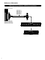
CPM2C CPU and Expansion I/O + XW2B/XW2C 20-pin Screw Terminal Blocks
CPM2C Connector type
CPM2C-C(1)DTC-D CPU Units with 16 pt DC IN/16 pt NPN OUT
CPM2C-E(D)TC Expansion I/O Modules with 16 pt DC IN/16 pt NPN OUT
OUTPUT
2 cables are required for each module
XW2Z-50A (0.5 m)
XW2Z-100A (1 m)
XW2Z-150A (1.5 m)
XW2Z-200A (2 m)
XW2Z-300A (3 m)
XW2Z-500A (5 m)
XW2B-20G4
INPUT
XW2C-20G5-IN16
Dedicated input screw terminal block
6
XW2B-20G5
XW2B-20G4
Reference Information
CPM2C CPU and Expansion I/O + G70A, G70D Relay I/O Blocks
CPM2C Connector type
CPM2C-C(1)DTC-D CPU Units with 16 pt DC IN/16 pt NPN OUT
CPM2C-E(D)TC Expansion I/O Modules with 16 pt DC IN/16 pt NPN OUT
G70D-VSOC16
OUTPUT
2 cables are required for each module
G79-100C (1 m)
G79-150C (1.5 m)
G79-200C (2 m)
G79-300C (3 m)
G79-500C (5 m)
G70A-ZOC16-3 +
G2R-1-S(N) relays
INPUT
G70A-ZOC16-3 +
G2R-1-S(N) relays
G70D-SOC16
CQM1H 16-point PNP Output Module + G70A Relay I/O Block
CQM1-OD214
(16 PNP outputs)
G79-Y100C
G79-Y150C
G79-Y200C
G79-Y300C
G79-Y500C
(1 m)
(1.5 m)
(2 m)
(3 m)
(5 m)
G70A-ZOC16-4 +
G2R-1-S(N) relays
7
Reference Information
CQM1H High-Density I/O Modules + XW2B Screw Terminal Blocks
CQM1H 32-Point I/O Modules
XW2Z-50B (0.5 m)
XW2Z-100B (1 m)
XW2Z-150B (1.5 m)
XW2Z-200B (2 m)
XW2Z-300B (3 m)
XW2Z-500B (5 m)
CQM1-ID213 (32 NPN inputs)
CQM1-ID214 (32 NPN inputs)
CQM1-OD213 (32 NPN outputs)
CQM1-OD216 (32 PNP outputs)
XW2B-40G5
XW2B-40G4
8
Reference Information
CQM1H High-Density Input Modules + XW2C Input Screw Terminal Blocks
CQM1H 32-Point Input Modules
1 - 1.5 - 2 - 3 - 5 m
0.75 - 1.25 - 1.75 - 2.75 - 4.75 m
CQM1-ID213 (32 NPN inputs)
CQM1-ID214 (32 NPN inputs)
XW2Z-100D
XW2Z-150D
XW2Z-200D
XW2Z-300D
XW2Z-500D
(1 m + 0.75 m)
(1.5 m + 1.25 m)
(2 m + 1.75 m)
(3 m + 2.75 m)
(5 m + 4.75 m)
XW2C-20G5-IN16
XW2C-20G5-IN16
9
Reference Information
CQM1H High-Density Output Modules + Output Relay Blocks
CQM1
1 - 1.5 - 2 - 3 - 5 m
.75 - 1.25 - 1.75 - 2.75 - 4.75 m
CQM1-OD213
(32 NPN outputs)
G79-O100C-75 (1 m + 0.75 m)
G79-O150C-125 (1.5 m+ 1.25 m)
G79-O200C-175 (2 m+ 1.75 m)
G79-O300C-275 (3 m+ 2.75 m)
G79-O500C-475 (5 m+ 4.75 m)
G70D-VSOC16
G7TC-OC16 Relay Block or
P7TF-OS16 Block Base with
G7T-1112S Relays or
G3TA-ODX02S SSRs
10
G70A-ZOC16-3 +
G2R-1-S(N) relays
G70D-SOC16
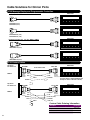
Cable Solutions for Omron PLCs
Operator Interface Terminals and CPM1A/CPM2A
Peripheral Port
CPM1A
Serial Port
Peripheral
Port
C200H-CN__0-EU
NT31C-CN__0-EU (for NT31C Port B only)
NT11S
NT20S / 600S
NT21 / 31 / 631
CPM1-CIF01
CPM2A
Serial Port
Operator Interface Terminals and CPM2C PLC
Serial
C200H-CN__0-EU
NT31C-CN__0-EU (for NT31C Port B only)
Port
CPM2CCIF01
CS1W-CN118
CPM2C-CN111
Peripheral
Port
XW2Z-200T-2
XW2Z-500T-2
(Recommended Cable)
NT11S
NT20S / 600S
NT21 / 31 / 631
CPM2C
11
Cable Solutions for Omron PLCs
Operator Interface Terminals and CPM2B PLC
CS1W-CN118
C200H-CN__0-EU
NT31C-CN__0-EU (for NT31C Port B only)
Peripheral Port
Serial Port
XW2Z-200T-2
XW2Z-500T-2
(Recommended Cable)
CPM2B
NT11S
NT20S / 600S
NT21 / 31 / 631
Operator Interface Terminals and CQM1H PLC
CS1W-CN118
C200H-CN__0-EU
NT31C-CN__0-EU (for NT31C Port B only)
Peripheral
Port
Serial
Port
Expansion
Serial Port
XW2Z-200T-2
XW2Z-500T-2
CQM1H
12
NT11S
NT20S / 600S
NT21 / 31 / 631
Cable Solutions for Omron PLCs
Operator Interface Terminals and CJ1 PLC
CS1W-CN118
Peripheral
Port
RS232C
Serial Modules
C200H-CN__0-EU
NT31C-CN__0-EU (for NT31C Port B only)
Serial Port
XW2Z-200T-2
XW2Z-500T-2
CJ1
NT11S
NT20S / 600S
NT21 / 31 / 631
Operator Interface Terminals and CS1 PLC
CS1W-CN118
RS232C
Serial
Modules
RS232C
Serial
Inner
Board
C200H-CN__0-EU
NT31C-CN__0-EU (for NT31C Port B only)
CS1
Serial Port
XW2Z-200T-2
XW2Z-500T-2
NT11S
NT20S / 600S
NT21 / 31 / 631
13
Cable Solutions for Omron PLCs
NT2S Message Display and Programmable Controllers
Peripheral port (Old type: C200H, SRM1, CPM2A, CPM1A)
NT2S-SF121
NT2S-CN212 (2 m)
NT2S-CN215 (5 m)
NT2S-SF122/123
NT2S-CN222-V1 (2 m)
NT2S-CN225-V1 (5 m)
NT2S-SF121
Peripheral port (New type: CJ1, CS1, CQM1H, CPM2C)
NT2S-CN223-V1 (2 m)
NT2S-SF122/123
NT2S-CN224-V1 (2 m)
NT2S Custom Cables
Any Omron
PLC Serial Port
RS232C
NT2S-SF121
Male DB9
Metric
Threads
2.6 mm
TXD
RXD
GROUND
Any Omron
PLC Serial Port
RS232C
Male DB9
Metric
Threads
2.6 mm
TXD
RXD
GROUND
5 VDC
14
Male DB9
Create custom cable
2
3
1
9
4
5
2
3
9
6
1
4
5
SHIELD
2
3
5
9
TXD
English
Threads
4-40 screw
RXD
GROUND
(Purchase Omron’s C200H-CN32O-EU and
short pins 5 and 9 on NT side as shown)
Female DB9
SHIELD
2
3
4
5
7
GROUND
TXD
NT2S-SF122
English
Threads
4-40 screw
VOLT IN (5 VDC)
GROUND
RXD (232)
Custom Cable Ordering Information
Description
Metric thread shell and screws - 2.6 mm
English thread shell and screws - 4-40 screw
Male connector
Female connector
Part Number
XM2S-0911
XM2S-0913
XM2A-0901
XM2D-0901
Cable Solutions for Multi-Vendor PLCs
Allen Bradley MicroLogix 1200
An alternative cable configuration uses a custom RS-232 9-to-9 PIN cable connecting to the Allen-Bradley
1767-CBL-PM02(Series C). The diagram below shows the pinouts for the custom RS-232 cable:
Connects to Omron NT
Connects to AB 1761 Cable
DCD
RXD
TXD
DTR
GROUND
DSR
RTS
CTS
RI
9 Pin Male
DB9 Connector
-1
TXD -2
RXD -3
-4
-5
-6
-7
-8
GROUND -9
9 Pin Male
DB9 Connector
123456789-
AB 1761-CBL-PM02
(Series C)
AB MicroLogix 1200 Communication Cables
1761-CBL-PM02(Series C)
DB9 to 8 pin mini-din connector (order from AB)
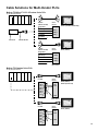
Allen Bradley SLC 5/02
Communicates via AB’s DF1 protocol. This PLC comes with only a DH-485 port. The Allen-Bradley 1747-KE module
must be purchased to provide a serial connection on the SLC 5/02. Connect the communication cable from the NT
to the serial port on the 1747-KE module.
AB SLC 5/02
1747-KE
RS232
DH-485
NT631C-CN321-EU
DH-485
NT31 (Port A)
NT631 (Port A or B)
1747-C13
Allen Bradley SLC 5/00, 5/01, 5/02
This cable can only be used in 1:1 connection
with DH485 port.
NT31C-CN321-EU
AB SLC 5/00, 5/01, 5/02
NT31 (Port B)
DH-485
NT631C-CN221-485
NT31 (Port A)
NT631 (Port A or B)
NT631C-CN221-485
AB SLC 5/02 Communication Cables and Accessories
NT31C-CN321-EU
NT31 (Port A)
3.0 m cable, 25 to 9 pin, NT to AB SLC PLC
NT631C-CN321-EU
3.0 m cable, 9 to 9 pin, NT to AB SLC PLC
1747-KE
DB9 Serial Port Module (order from AB)
1747-C13
DH-485 module connection cable
V060-E1-2
Operation Manual – Multi-vendor Connection
15
Cable Solutions for Multi-Vendor PLCs
Allen Bradley SLC 5/03, 5/04, 5/05
Communicates via AB’s DF1 protocol. Connect the communication cable from the NT to a serial port on the PLC using Omron cable part numbers.
AB SLC 5/03, 5/04, 5/05
DF1
RS232
NT631C-CN321-EU
NT31 (Port A)
NT631 (Port A or B)
Allen Bradley SLC 5/03, 5/04, 5/05
NT31C-CN321-EU
This cable can only be used in 1:1 connection
with DH485 port.
NT31 (Port B)
AB SLC 5/03, 5/04, 5/05
DH-485
NT631C-CN211-485
NT31 (Port A)
NT631 (Port A or B)
NT631C-CN211-485
NT31 (Port A)
AB SLC 5/02 Communication Cables and Accessories
NT31C-CN321-EU
3.0 m cable, 25 to 9 pin, NT to AB SLC PLC
NT631C-CN321-EU
3.0 m cable, 9 to 9 pin, NT to AB SLC PLC
V060-E1-2
Operation Manual – Multi-vendor Connection
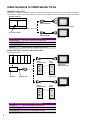
GE 90-20 and 90-30 Series PLCs
Communicates via GE’s SNP-X protocol. The Omron NT is communicating RS-232, while the GE PLC uses RS-422. An RS232 to
RS422 converter (HE693SNP232A) is needed to complete communications.
GE 90-20 and 90-30 Series
SNP
NT631C-CN322-EU
NT31 (Port A)
NT631 (Port A or B)
HE693SNP232A
NT31C-CN322-EU
GE 90-20 and 90-30 Series Communication Cables and Accessories
16
NT31C-CN322-EU
3.0 m cable, 25 to 9 pin, NT to GE PLC
NT631C-CN322-EU
3.0 m cable, 9 to 9 pin, NT to GE PLC
HE693SNP232A
RS232 to RS422 adapter (order from GE)
V060-E1-2
Operation Manual – Multi-vendor Connection
NT31 (Port B)
Cable Solutions for Multi-Vendor PLCs
Siemens S7-300 and S7-400 Series PLCs
Communicates with Siemens HMI Adapter protocol. The Omron NT is communicating RS-232 to the Siemens HMI adapter,
6E57-972-OCA10-OXAO. The adapter is necessary to convert the HMI Adapter protocol into the Siemens proprietary MPI protocol.
Siemens S7-300 and S7-400 Series
MPI
NT631C-CN323-EU
NT31 (Port A)
NT631 (Port A or B)
6E57-972-0CA10-OXAO
NT31C-CN323-EU
Siemens S7-300 and S7-400 Communication Cables and Accessories
NT31C-CN323-EU
3.0 m cable, 25 to 9 pin, NT to Siemens PLC
NT631C-CN323-EU
3.0 m cable, 9 to 9 pin, NT to Siemens PLC
6E57-972-OCA10-OXAO
HMI Adapter for MPI protocol (order from Siemens)
V060-E1-2
Operation Manual – Multi-vendor Connection
NT31 (Port B)
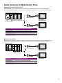
Mitsubishi A-Series PLCs
Communicates using Mitsubishi’s Computer Link protocol. The Omron NT and the Mitsubishi A-Series PLC are communicating using
RS-232 communications. Communications can be RS-422 by using custom cables as specified in Operation Manual V042-E1-1.
Mitsubishi A-Series
NT631C-CN324-EU
NT31 (Port A)
NT631 (Port A or B)
Computer Link Module
NT31C-CN324-EU
Mitsubishi A-Series Communication Cables and Accessories
NT31C-CN324-EU
3.0 m cable, 25 to 9 pin, NT to Mits-A PLC
NT631C-CN324-EU
3.0 m cable, 9 to 9 pin, NT to Mits-A PLC
V042-E1-1
Operation Manual – PC (Mitsubishi) Connection
NT31 (Port B)
17
Cable Solutions for Multi-Vendor PLCs
Mitsubishi FX-Series PLCs
Communicates via Mitsubishi’s Computer Link protocol. The Omron NT and Mitsubishi FX-Series PLC are communicating using RS422
communications. The NT31 cable connects from the 25-pin port B, while the NT631 connects from the RS422 terminal screws for Port B.
Mitsubishi FX-Series
NT631C-CN325-EU
NT631 (Port B Terminal Strip)
25 Pin Connector RS422
NT31C-CN325-EU
NT31 (Port B)
Mitsubishi A-Series Communication Cables and Accessories
NT31C-CN325-EU
3.0 m cable, 25 to 25 pin, NT to Mits-FX PLC
NT631C-CN325-EU
3.0 m cable, 4 Wires to 25 pin, NT to Mits-FX PLC
FX-20P-CADP
Cable for FX0 & FX0N PLC (buy from Mitsubishi)
V042-E1-1
Operation Manual – PC (Mitsubishi) Connection
Modicon TSX Micro 37-21/22 & Premium Series PLCs
For RS-232C connection:
PLC Side
(TSX SCP CD 1030)
Omron
NT Side
3
2
5
4
7
2 SD
3 RD
RXD
TXD
CTS
RTS
SG
TSX SCP111
9 Pin Male
Metric Thread
PLC Side
(TSX SCP CD 1030)
Omron
NT Side
3
2
5
4
7
2 SD
3 RD
RXD
TXD
CTS
RTS
SG
25 Pin Female
Modicon TSX Series Communication Cables and Accessories
18
9 SG
25 Pin Female
TSX SCP CD 1030
TSX SCP111
Multi-protocol PCMCIA card for RS-232C
TSX SCP114
Multi-protocol PCMCIA card for RS-422A
TSX SCP CD 1030
Connecting cable for PCMCIA for RS-232C
TSX SCP CM 4030
Connecting cable for PCMCIA for RS-422A
NT31 (Port A)
NT631 (Port A or B)
7 SG
25 Pin Male
Metric Thread
NT31 (Port B)
Cable Solutions for Multi-Vendor PLCs
Modicon TSX Micro 37-21/22 & Premium Series PLCs
For RS-422A connection:
PLC Side
(TSX SCP CX 4030)
Orange/White
White/Orange
White/Green
Green/White
Omron
NT Side
NT631 (Port B Terminal Strip)
SDB(+)
SDA(-)
RDB(+)
RDA(-)
Brown/White
Terminal
TSX SCP114
TSX SCP CM 4030
PLC Side
(TSX SCP CX 4030)
Omron
NT Side
Orange/White
11 SDB(+)
White/Orange
15 SDA(-)
White/Green
10 RDB(+)
Green/White
16 RDA(-)
NT31 (Port B)
Brown/White
25 Pin Male
Metric Thread
Modicon TSX Quantum Series PLCs
For RS-232C connection:
PLC Side
Shield
RXD
TXD
DTR
GND
DSR
RTS
CTS
1
2
3
4
5
6
7
8
9
PLC Side
Shield
RXD
TXD
DTR
GND
DSR
RTS
CTS
1
2
3
4
5
6
7
8
9
Omron
NT Side
1
2 TXD
3 RXD
4
5
6
7
8
9 GND
9 Pin Male
Metric Thread
Omron
NT Side
1
2 TXD
3 RXD
4
5
6
7 GND
25 Pin Male
NT31 (Port A)
NT631 (Port A or B)
NT31 (Port B)
19
OMRON ELECTRONICS LLC
1 Commerce Drive
Schaumburg, IL 60173 USA
800.55.OMRON (66766)
OMRON CANADA, INC.
885 Milner Avenue
Scarborough, Ontario M1B 5V8
416.286.6465
OMRON ON-LINE
Global - http://www.omron.com
USA - http://www.omron.com/oei
Canada - http://www.omron.com/oci
©2002 OMRON ELECTRONICS LLC
Printed in the U.S.A.
Specifications subject to change without notice.
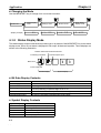
9
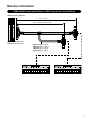
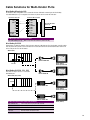
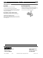
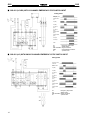
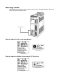
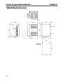
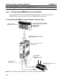
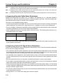
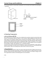
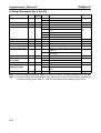
3RVLWLRQ &RQWURO 7HUPLQDO %ORFN
;:5%
6LPSOLI\ :LULQJ EHWZHHQ 0RWRU
&RQWUROV DQG 2PURQ·V 3RVLWLRQ
&RQWURO 3/& 0RGXOHV
1 5HOD\V FRQWURO VLJQDOV EHWZHHQ D VHUYR
GULYHU DQG WKH 3/& SRVLWLRQ FRQWURO
PRGXOH RU &404 3/& ZLWK EXLOW00LQ
SXOVH ,22 FDSDELOLW\
1 &RQQHFWRUV DUH ZLUHG ZLWK D VLQJOH
VFUHZGULYHU DQG QR VROGHULQJ LV UHTXLUHG
1 'HGLFDWHG FDEOHV FRQQHFW WHUPLQDO
EORFNV WR SRVLWLRQ FRQWURO PRGXOHV
1 5HTXLUHV 57 9'& IRU FRQWURO VLJQDO XVH
1 7HUPLQDO EORFN RUJDQL]HV ZLULQJ DQG
VDYHV VSDFH> XVHV 06 VFUHZV
1 0RXQWV WR ',1 WUDFN RU ZLWK VFUHZV IRU
SDQHO PRXQWLQJ
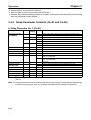
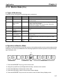
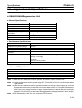
2UGHULQJ ,QIRUPDWLRQ
3 326,7,21 &21752/ 7(50,1$/ %/2&.6
$SSHDUDQFH
$SSOLFDEOH VHUYR GULYHU
800VHULHV= 5;;'0083PPP
$SSOLFDEOH SRVLWLRQ FRQWURO
PRGXOH2&404 &38
3DUW QXPEHU
&533+001&445
&533+:001&446
;:5%0053-9004%
&533+001&544
&533+:001&546
&533+:001&746
;:5%0073-9005%
&40400&387600(94
;:5%0053-9006%
;:5%
;:5%
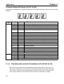
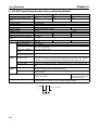
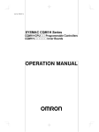
3 &$%/(6
&DEOHV %HWZHHQ 6HUYR 'ULYHU DQG 7HUPLQDO %ORFN
$SSHDUDQFH
3RVLWLRQ FRQWURO
WHUPLQDO EORFN
;:5%0053-9004%/
;:5%0073-9005%
+6HH QRWH,
;:5%0053-9006%
$SSOLFDEOH VHUYR GULYHU
5;;'0083PPP
&DEOH OHQJWK
3DUW QXPEHU
4 P +615; IW,
;:5=00433-00%4
5 P +9189 IW,
;:5=00533-00%4
1RWH= 7ZR FDEOHV ZLOO EH UHTXLUHG RQ WKH 6HUYR 'ULYHU VLGH LI WKH ;:5%0073-9005% 7HUPLQDO %ORFN LV XVHG IRU WZR00D[LV FRQWURO1
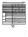
&DEOHV %HWZHHQ 3/& 3RVLWLRQ &RQWURO 0RGXOH DQG 7HUPLQDO %ORFN
$SSHDUDQFH
3RVLWLRQ FRQWURO
WHUPLQDO EORFN
;:5%0053-9004%
;:5%0073-9005%
$SSOLFDEOH SRVLWLRQ
FRQWURO PRGXOH
&533+001&445 +IRU RQH D[LV,
&533+001&544 +IRU WZR D[HV,
&DEOH OHQJWK
3DUW QXPEHU
318 P +4197 IW,
;:5=00383-00$4
4 P +615; IW,
;:5=00433-00$4
318 P +4197 IW,
;:5=00383-00$5
4 P +615; IW,
;:5=00433-00$5
;:5%0053-9006%
+6HH QRWH 4,
&40400&387600(94 +IRU RQH RU
WZR D[HV,
318 P +4197 IW,
;:5=00383-00$6
4 P +615; IW,
;:5=00433-00$6
;:5%0053-9004%
&533+001&446 +IRU RQH D[LV,
318 P +4197 IW,
;:5=00383-00$9
4 P +615; IW,
;:5=00433-00$9
318 P +4197 IW,
;:5=00383-00$:
4 P +615; IW,
;:5=00433-00$:
;:5%0073-9005%
+6HH QRWH 5,
&533+:001&546 +IRU WZR D[HV,
&533+:001&746 +IRU IRXU D[HV,
1RWH= 41 7ZR FDEOHV HDFK ZLOO EH UHTXLUHG RQ WKH 6HUYR 7HUPLQDO %ORFN DQG 3RVLWLRQ &RQWURO 0RGXOH VLGH/ DQG RQ WKH 6HUYR 'ULYHU VLGH LI
WKH &40400&3876 LV XVHG IRU WZR D[HV1
51 7ZR FDEOHV HDFK ZLOO EH UHTXLUHG RQ WKH 6HUYR 7HUPLQDO %ORFN DQG 3RVLWLRQ &RQWURO 0RGXOH VLGH/ DQG RQ WKH 6HUYR 'ULYHU VLGH LI
WKH &533+:001&746 +IRXU D[HV, LV XVHG IRU WZR D[HV1
5
;:5%
;:5%
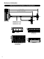
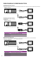
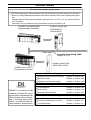
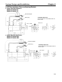
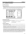
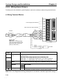
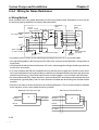
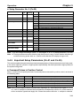
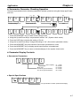
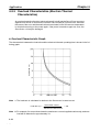
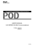
$SSOLFDWLRQ ([DPSOHV
5('8&( :,5,1* 72 (;7(51$/ 6(16256/ 6:,7&+(6 $1' 32:(5 6833/<
&RQYHQWLRQDO 0HWKRG 5HTXLUHV 0DMRU :LULQJ (IIRUW1
3RVLWLRQ &RQWURO 0RGXOH
6HUYR 'ULYHU
7KH FRQQHFWRUV DUH VROGHUHG1
&RQQHFWRU RQ WKH
3RVLWLRQ &RQWURO
0RGXOH VLGH
&RQQHFWRU RQ WKH
6HUYR 'ULYHU VLGH
3RZHU
VXSSO\
6ZLWFK26HQVRU
6HUYR &RQWURO 7HUPLQDO %ORFN
$OO ZLUHV DUH FRQQHFWHG WR WKH 6HUYR &RQWURO 7HUPLQDO %ORFN ZLWK HDVH1
3RVLWLRQ &RQWURO 0RGXOH
6HUYR 7HUPLQDO %ORFN
6HUYR 'ULYHU
3RZHU
VXSSO\
6ZLWFK26HQVRU
x 5HOD\V FRQWURO VLJQDOV EHWZHHQ WKH 6HUYR 'ULYHU DQG WKH 3RVLWLRQ &RQWURO
0RGXOH ZLWK PLQLPDO ZLULQJ HIIRUW1
x &RQQHFWRUV DUH ZLUHG ZLWK D VLQJOH VFUHZGULYHU DQG QR VROGHULQJ LV UHTXLUHG1
x 'HGLFDWHG &DEOH FRQQHFWV 8QLWV1
6
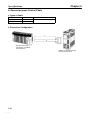
;:5%
;:5%
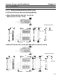
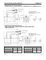
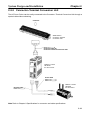
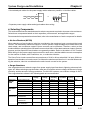
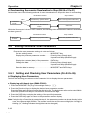
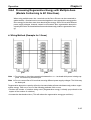
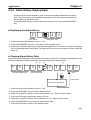
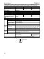
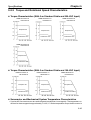
3 7<3,&$/ &21),*85$7,216
3RVLWLRQ &RQWURO 0RGXOH/
DQG &404
&DEOH RQ WKH 3RVLWLRQ &RQWURO
0RGXOH VLGH
6HUYR 7HUPLQDO %ORFN
&DEOH RQ WKH 6HUYR 'ULYHU
VLGH
6HUYR 'ULYHU
+VHH QRWH 5/ 6 DQG 7,
3RVLWLRQ &RQWURO 0RGXOH
+IRU RQH D[LV, IRU &533+
&533+001&445
3RVLWLRQ &RQWURO 0RGXOH
+IRU RQH D[LV, IRU &533+
&DEOH IRU &533+001&445
;:5=00PPP-00$4
&DEOH IRU &533+:00
1&446
&533+:001&446
;:5=00PPP-00$9
3RVLWLRQ &RQWURO 0RGXOH
+IRU WZR D[LV, IRU &533+
&DEOH IRU &533+001&544
&533+001&544
;:5=00PPP-00$5
+VHH QRWH 8,
3RVLWLRQ &RQWURO 0RGXOH
+IRU WZR D[HV2IRXU D[HV,
IRU &533+:
&533+:001&546
&533+:001&746
&DEOH IRU &533+:001&546
+WZR D[HV, DQG &533+:00
1&746 +IRXU D[HV,
;:5=00PPP-00$:
6HUYR 7HUPLQDO %ORFN IRU
&533+001&445
;:5%0053-9004% +VHH QRWH 4,
800VHULHV &DEOH
;:5=00PPP-00%4
800VHULHV 6HUYR 'ULYHU
5;;'0083PPP
6HUYR 7HUPLQDO %ORFN IRU
&533+:001&446
;:5%0053-9004% +VHH QRWH 4,
6HUYR 7HUPLQDO %ORFN IRU
&533+001&544
;:5%0073-9005% +VHH QRWH
4,
+VHH QRWH 8,
6HUYR 7HUPLQDO %ORFN IRU
&533+:001&546 +WZR D[HV, DQG
&533+:001&746 +IRXU D[HV,
;:5%0073-9005% +VHH QRWH 7,
+VHH QRWH 6,
+VHH QRWH 6,
&404 +IRU RQH2WZR D[HV,
&DEOH IRU
&40400&387600(94
6HUYR 7HUPLQDO 8QLW IRU
&40400&387600(94
&40400&387600(94
;:5=00PPP-00$6
;:5%0053-9006 +VHH QRWH 4,
1RWH= 41 +DV WKH IXQFWLRQV RI WKH FRQYHQWLRQDO ;:5%0053-9004/ ;:5%0073-9005 DQG ;:5%0053-90061
51 7ZR FDEOHV ZLOO EH UHTXLUHG RQ WKH 6HUYR GULYHU VLGH LI WKH &533+001&544 +IRU WZR D[HV, LV XVHG1
61 7ZR FDEOHV HDFK DUH UHTXLUHG RQ WKH 6HUYR 7HUPLQDO %ORFN DQG 3RVLWLRQ &RQWURO 0RGXOH VLGH DQG RQ WKH 6HUYR 'ULYHU VLGH LI WKH
&40400&387600(94 LV XVHG IRU WZR D[HV1
71 7ZR FDEOHV HDFK ZLOO EH UHTXLUHG RQ WKH 6HUYR 7HUPLQDO %ORFN DQG 3RVLWLRQ &RQWURO 0RGXOH VLGH DQG RQ WKH 6HUYR 'ULYHU VLGH LI
WKH &533+:001&746 +IRXU D[HV, LV XVHG1
7
;:5%
;:5%
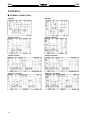
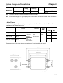
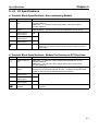
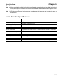
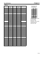
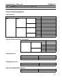
6SHFLILFDWLRQV
3 326,7,21 &21752/ 7(50,1$/ %/2&.6
,WHP
;:5%00P
PP-900P
P%
5DWHG FXUUHQW
4 $ DW D WHPSHUDWXUH RI 63q& +;9q), PD[1
5DWHG YROWDJH
57 9G&
,QVXODWLRQ UHVLVWDQFH
8 0: PLQ1 DW 833 9'&
'LHOHFWULF VWUHQJWK
833 9$& IRU 4 PLQXWH ZLWK D FXUUHQW OHDNDJH RI 4 P$ PD[1
(QFORVXUH UDWLQJ
,333
(OHFWULFDO SURWHFWLRQ
&ODVV 3
$PELHQW WHPSHUDWXUH
2SHUDWLQJ= 003q& WR 88q& +65q) WR 464q),
3 &211(&7256
,WHP
;:5=00P-00$P200%P
5DWHG FXUUHQW
4$
5DWHG YROWDJH
57 9'&
&RQWDFW UHVLVWDQFH
53 P: PD[1 ZLWK 433 P$ PD[1 DW 53 P9 PD[1 +6HH QRWH 4,
,QVXODWLRQ UHVLVWDQFH
8 0: PLQ1 DW 833 9'&
'LHOHFWULF VWUHQJWK
833 9$& IRU 4 PLQXWH ZLWK D FXUUHQW OHDNDJH RI 4 P$ PD[1 +6HH QRWH 5,
(QFORVXUH UDWLQJ
,333
(OHFWULFDO SURWHFWLRQ
&ODVV 3
$PELHQW WHPSHUDWXUH
2SHUDWLQJ= 3q& WR 88q& +65q) WR 464q),
1RWH= 41 7KH UHVLVWDQFH LQGLFDWHG LV WKH FRQWDFW UHVLVWDQFH RI WKH FRQQHFWRU1
51 7KH YROWDJH LQGLFDWHG LV WKH GLHOHFWULF VWUHQJWK RI WKH FRQQHFWRU1
8
;:5%
;:5%
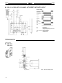
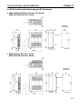
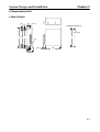
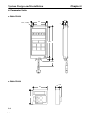
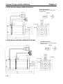
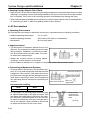
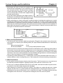
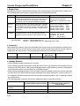
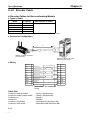
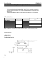
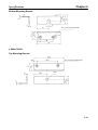
'LPHQVLRQV
8QLW= PP +LQFK,
3 326,7,21 &21752/ 7(50,1$/ %/2&.6
&404 VLGH
;:5% 00 53-9 00 4%
6HUYR VLGH
618
468 +8164,
67
5<18
+4149,
7ZR/ 618 GLD1 KROHV
4818
78
+41::,
:18
:
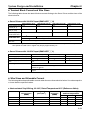
&RQQHFWLRQ WR 7HUPLQDO %ORFN
7KH WHUPLQDO VLJQDO QDPH YDULHV ZLWK WKH VHUYR
GULYHU1 5HIHU WR WKH 2SHUDWLRQ 0DQXDO RI WKH VHUYR
GULYHU LQ XVH1
,GHQWLI\ WKH VHUYR GULYHU LQ XVH E\ ZULWLQJ WKH QDPH
RQ WKH WHUPLQDO QDPHSODWHV SURYLGHG1 $IIL[ WKH
QDPHSODWH WR WKH WHUPLQDO FRYHU1
618
6<
:195
915
06
51;
7HUPLQDO EORFN +53 3,
ZLWK URWDU\ FRYHU
79
+41;4,
7716
+41:7,
5318
51;
1RWH= 7KH WHUPLQDO EORFN KDV D WHUPLQDO SLWFK RI :195 PP1
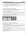
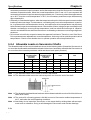
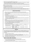
&RQQHFWLRQ WR 2QH $[LV 3RVLWLRQ &RQWURO 0RGXOHV
&533+001&4450082&533+:001&446008
1RWH= 41 8VH PRGH 5 IRU RULJLQ VHDUFK1
51 7KH ;% FRQWDFW LV XVHG WR WXUQ WKH HOHFWURPDJQHWLF
EUDNH 21 DQG 2))1
61 7KH RSHQ WHUPLQDO PXVW EH OHIW XQFRQQHFWHG1
71 3 9 DQG &RPPRQ WHUPLQDOV DUH FRQQHFWHG LQWHUQDOO\1
81 7KH VXLWDEOH FULPS WHUPLQDO LV 54158006 +URXQG RU IRUN
W\SH,1
9
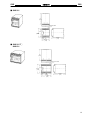
;:5%
;:5%
;:5%0073-9005%
1& 0RGXOH VLGH
618
5<18
+4149,
;00D[LV 6HUYR VLGH
<00D[LV 6HUYR VLGH
4;3 +:13<,
9619 +5183,
871: +5148,
7ULDQJOH PDUN
618
4818
:18
78
+41::,
7ZR/ 618
GLD1 KROHV
:195
:
915
06
7HUPLQDO EORFN +73 3, ZLWK URWDU\ FRYHU
&RQQHFWLRQ WR 7HUPLQDO %ORFN
51;
79
+41;4,
7KH WHUPLQDO VLJQDO QDPH YDULHV ZLWK WKH
VHUYR GULYHU1 5HIHU WR WKH 2SHUDWLRQ 0DQXDO
RI WKH VHUYR GULYHU LQ XVH1
7716
+41:7,
5318 51;
,GHQWLI\ WKH VHUYR GULYHU LQ XVH E\ ZULWLQJ
WKH QDPH RQ WKH WHUPLQDO QDPHSODWHV
SURYLGHG1 $IIL[ WKH QDPHSODWH WR WKH
WHUPLQDO FRYHU1
1RWH= 7KH WHUPLQDO EORFN KDV D WHUPLQDO SLWFK RI :195 PP1
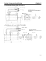
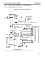
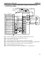
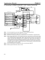
RQQHFWLRQ WR 0XOWL $[LV 3RVLWLRQ &RQWURO 0RGXOHV
533+001&5440082&533+:001&5460082&533+:001&746008
;2<00D[0 ;00D[0
LV HPHU00 LV &:
JHQF\
OLPLW
VWRS
&RP00
PRQ
;00D[0
;00D[0
;00D[0
LV
LV RUL0
LV
&&:
JLQ
581
OLPLW
SUR[00
LPLW\
;00D[LV
&RP00
&RP00
&RP
UHPRWH
PRQ
00PRQ
LQWHUUXSW PRQ
;00D[LV
0,1*
&RP00
PRQ
;00D[LV
$/0
;00D[LV
5(6(7
;00D[0
LV
%.,5
<00
D[LV
&:
OLPLW
;00
D[LV
$/0
&20
<00
D[LV
&&:
OLPLW
&RP00
PRQ
<00D[LV
RULJLQ
SUR[00
LPLW\
&RP00
PRQ
<00D[LV
581
<00D[LV
UHPRWH &RP00
LQWHUUXSW PRQ
<00D[LV
0,1*
&RP00
PRQ
<00D[LV
$/0
<00D[LV
5(6(7
<00D[LV
$/0
&20
+VHH
QRWH 4,
+VHH
QRWH 4,
57
9'&
<00
D[LV
%.,5
57
9'&
57 9'&
1RWH= 41
51
61
71
81
91
7KH ;% FRQWDFW LV XVHG WR WXUQ WKH HOHFWURPDJQHWLF EUDNH RQ DQG RII1
8VH PRGH 5 IRU RULJLQ VHDUFK1
:KHQ RQO\ D VLQJOH D[LV LV XVHG/ VKRUW00FLUFXLW WKH XQXVHG D[LV· &: OLPLW DQG &&: OLPLW WR WKH FRPPRQ WHUPLQDO1
7KH RSHQ WHUPLQDO PXVW EH OHIW XQFRQQHFWHG1
3 9 DQG FRPPRQ WHUPLQDOV DUH FRQQHFWHG LQWHUQDOO\1
7KH VXLWDEOH FULPS WHUPLQDO LV 54158006 +URXQG RU IRUN W\SH,1
:
;:5%
;:5%
&404 VLGH
;:5%0053-9006%
6HUYR VLGH
618
468 +8164,
67
618
6<
5<18
+4149,
7ZR/ 618 GLD1 KROHV
4818
:18
78
+41::,
:
:195
915
06
51;
7HUPLQDO EORFN +53 3,
ZLWK URWDU\ FRYHU
&RQQHFWLRQ WR 7HUPLQDO %ORFN
7KH WHUPLQDO VLJQDO QDPH YDULHV ZLWK WKH VHUYR
GULYHU1 5HIHU WR WKH 2SHUDWLRQ 0DQXDO RI WKH VHUYR
GULYHU LQ XVH1
7716
+41:7,
,GHQWLI\ WKH VHUYR GULYHU LQ XVH E\ ZULWLQJ WKH QDPH
RQ WKH WHUPLQDO QDPHSODWHV SURYLGHG1 $IIL[ WKH
QDPHSODWH WR WKH WHUPLQDO FRYHU1
5318
79
+41;4,
51;
1RWH= 7KH WHUPLQDO EORFN KDV D WHUPLQDO SLWFK RI :195 PP1
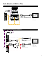
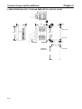
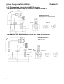
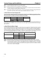
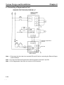
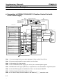
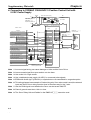
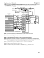
&RQQHFWLRQ WR 3RVLWLRQ &RQWURO 3/&
&40400&387600(94 IRU 400 RU 500$[LV &RQWURO
+VHH
+VHH
QRWH 4, QRWH 4,
&404 ,QSXW 8QLW
&RPPRQ &RPPRQ
+VHH
QRWH 5,
57 9'&
;
57
9'&
1RWH= 41 :KHQ WKLV VLJQDO LV LQSXW/ WKH RXWSXW SXOVHV
RI WKH &404 FDQ EH LQSXW WR WKH
KLJK00VSHHG FRXQWHUV GLUHFWO\1
51 ,QSXW WKLV VLJQDO RXWSXW WR WKH &404 LQSXW
PRGXOHV
61 7KH ;% FRQWDFW LV XVHG WR WXUQ WKH HOHFWUR0
PDJQHWLF EUDNH RQ DQG RII1
71 3KDVH = LV DQ RSHQ FROOHFWRU RXWSXW1
81 7KH RSHQ WHUPLQDO PXVW EH OHIW XQFRQ0
QHFWHG1
91 3 9 DQG FRPPRQ WHUPLQDOV DUH FRQQHFWHG
LQWHUQDOO\1
:1 7KH VXLWDEOH FULPS WHUPLQDO LV 54158006
+URXQG RU IRUN W\SH,1
;:5%
;:5%
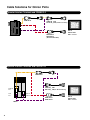
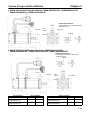
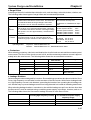
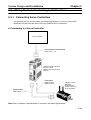
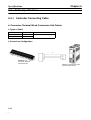
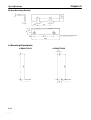
3 ;:5= &211(&7,1* &$%/(6
8VH WKH FDEOHV WR FRQQHFW WKH 3/& 3RVLWLRQ &RQWURO 0RGXOH WR WKH ;:5% 6HUYR 7HUPLQDO %ORFNV1
)RU &533+001&445 8VH
:LULQJ 'LDJUDP
;:5=00PPP-00$4
;:5=00PPP-00$4
&533+001&445
+3&% ,22 FRQQHFWRU
ZLWK 73 SROHV,
;:5%0053-9004%
+;*70005963,
&RQQHFWRU
3RVLWLRQ &RQWURO
0RGXOH VLGH
)&10069:-37300$82
) +)XMLWVX,
6HUYR 7HUPLQDO
%ORFN VLGH
;*70005963007
)RU &533+:001&446 8VH
;:5=00PPP-00$9
:LULQJ 'LDJUDP
;:5=00PPP-00$9
&533+001&446
+3&% ,22 FRQQHFWRU
ZLWK 73 SROHV,
;:5%0053-9004%
+;*70005963007,
&RQQHFWRU
3RVLWLRQ &RQWURO
0RGXOH VLGH
)&10069:-37300$82
) +)XMLWVX,
6HUYR 7HUPLQDO
%ORFN VLGH
;*70005963007 &ULPS WHUPLQDO
<
;:5%
;:5%
)RU &533+001&544 8VH
:LULQJ 'LDJUDP
;:5=00PPP-00$5
;:5=00PPP-00$5
&533+001&544
+0XOWL00SROH VTXDUH
FRQQHFWRU ZLWK 67 SROHV,
;:5%0073-9005%
+;*70006763,
&RQQHFWRU
3RVLWLRQ &RQWURO
0RGXOH VLGH
+HDW00VKULQNDEOH
WXEH
050067/)
++RQGD 7VXVKLQ .RJ\R,
6HUYR 7HUPLQDO
%ORFN VLGH
;*70006763007
)RU &533+:001&54621&746 8VH
;:5=00PPP-00$:
:LULQJ 'LDJUDP
;:5=00PPP-00$:
&533+001&54621&746
+0XOWL00SROH VTXDUH
FRQQHFWRU ZLWK 67 SROHV,
&RQQHFWRU
3RVLWLRQ &RQWURO
0RGXOH VLGH
050067/)
++RQGD 7VXVKLQ .RJ\R,
6HUYR 7HUPLQDO
%ORFN VLGH
;*70006763007
&ULPS WHUPLQDO
43
;:5%0073-9005%
+;*70006763007,
;:5%
;:5%
)RU &404 8VH
:LULQJ 'LDJUDP
;:5=00PPP-00$6
;:5=00PPP-00$6
&40400&387600(94
+;05'004834,
;:5%0053-9006%
+;*70004963,
&RQQHFWRU
3RVLWLRQ &RQWURO
3/& &38 VLGH
6HUYR 7HUPLQDO
%ORFN VLGH
+RRG FRYHU
;05'004834 6RFNHW
;056004844 +RRG
;*70004963007
)RU 8006HULHV 6HUYR 'ULYHU DQG 0RWLRQ &RQWRUO 7HUPLQDO %ORFN
;:5=00PPP-00%4
:LULQJ 'LDJUDP
;:5=00PPP-00%4
5;;'0083PPP
++DOI00SLWFK
FRQQHFWRU ZLWK 69
SROHV,
;:5%00PP-900P%
+;*70005363,
;:5=00PPP-00%
8
5;;'0083PPP
++DOI00SLWFK
FRQQHFWRU ZLWK 69
SROHV,
;:5%00PP-900P%
+;*70005363,
&RQQHFWRU
6HUYR 'ULYHU VLGH
6HUYR 7HUPLQDO
%ORFN VLGH
+HDW00VKULQNDEOH
WXEH
434690063339( 3OXJ
436690085$30033;
+RRG +ERWK 6XPLWRPR
60,
;*70005363007
44
;:5%
;:5%
3UHFDXWLRQV
3 :,5,1*
3 75$&. 02817,1*
7KH RSHQ WHUPLQDO PXVW EH OHIW XQFRQQHFWHG1
0RUH WKDQ RQH ;:5% 6HUYR 7HUPLQDO 8QLW FDQ EH GHQVHO\
PRXQWHG WR D ',1 WUDFN/ LQ ZKLFK FDVH/ PRYH WKH PRXQWLQJ VWD\V
IURP ERWK VLGHV RI WKH ;:5% WR WKH ERWWRP RI WKH ;:5%1
3 9 DQG FRPPRQ WHUPLQDOV DUH FRQQHFWHG LQWHUQDOO\1
'R QRW ZLUH WKH 6HUYR 7HUPLQDO %ORFN ZKLOH SRZHU LV VXSSOLHG WR
WKH XQLW/ RU WKH WHUPLQDOV PD\ EH VKRUW00FLUFXLWHG ZLWK WKH FDEOH
DQG WKH 8QLW PD\ PDOIXQFWLRQ1
6HFXUH ERWK HQGV RI WKH ;:5% ZLWK HQG SODWHV1
3 7(50,1$/ :,5( &211(&7,216
7KH VXLWDEOH FULPS WHUPLQDO LV 54158006 +URXQG RU IRUN W\SH,1
7HUPLQDO 6FUHZ 7LJKWHQLQJ 7RUTXH
:KHQ FRQQHFWLQJ FULPS WHUPLQDOV RU ZLUHV WR WKH WHUPLQDO EORFN/
EH VXUH WR WLJKWHQ HDFK FULPS WHUPLQDO RU ZLUH WR 318 WR 31; 1 x P
+71< WR :1; NJI x FP,1
127(= ',0(16,216 6+2:1 $5( ,1 0,//,0(7(561 7R FRQYHUW PLOOLPHWHUV WR LQFKHV GLYLGH E\ 58171
9
20521 (/(&7521,&6/ ,1&1
20521 &$1$'$/ ,1&1
400;3300880020521
749005;9009798
2QH (DVW &RPPHUFH 'ULYH
6FKDXPEXUJ/ ,/ 934:6
&DW1 1R1 353%)$'4
34233
;;8 0LOQHU $YHQXH
6FDUERURXJK/ 2QWDULR 04% 89;
6SHFLILFDWLRQV VXEMHFW WR FKDQJH ZLWKRXW QRWLFH1
3ULQWHG LQ 8161$1
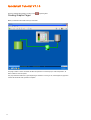
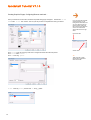
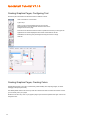
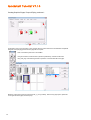
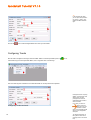
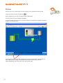
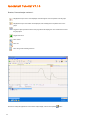
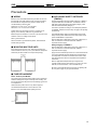
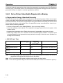
Quickstart Tutorial V7.10
In approximately one hour, completing this tutorial will give
you a basic working knowledge of CitectHMI/SCADA version
7.10 software.
Learn how to build a small project, configure dynamic
graphics, create alarms and trends, and then run your
project like a real plant.
This tutorial will also show you some shortcuts that, over
time, will save you far more than the one hour you may take
to complete the exercises inside.
1
Page
1 of 80
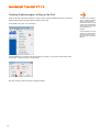
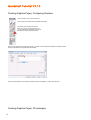
Quickstart Tutorial V7.10
Quickstart Tutorial ..................................................................................................................................................................3
Definition of Terms .................................................................................................................................................................4
Create a New Project Folder ..................................................................................................................................................6
Configuring Clusters ...............................................................................................................................................................7
Configure an I/O Device .......................................................................................................................................................11
Configuring Tags ..................................................................................................................................................................14
Creating Graphic Pages .......................................................................................................................................................17
Creating Graphic Pages, Creating a new page ....................................................................................................................18
Creating Graphic Pages, Saving your page .........................................................................................................................19
Creating Graphics pages, Setting up the Grid ......................................................................................................................20
Creating Graphics pages, Configuring buttons.....................................................................................................................21
Creating Graphics Pages, Configuring Symbol Sets ............................................................................................................27
Creating Graphics Pages, Aligning Objects..........................................................................................................................30
Creating Graphics Pages, Formatting with Rectangles ........................................................................................................32
Testing Graphics Pages, Computer Setup Wizard ...............................................................................................................35
Testing Graphics Pages, Runtime ........................................................................................................................................38
Creating Graphics Pages, Analog Indicators & Controls ......................................................................................................40
Creating Graphics Pages, Configuring Text .........................................................................................................................44
Creating Graphics Pages, Creating Colors...........................................................................................................................44
Creating Graphics Pages, Configuring Numbers..................................................................................................................46
Creating Graphics Pages, 3D rectangles .............................................................................................................................46
Creating Graphics Pages, Pumps & Piping ..........................................................................................................................48
Creating Graphics Pages, Managing True Colors ................................................................................................................53
Accessing Alarm and Trend Display Pages..........................................................................................................................55
Configuring Alarms ...............................................................................................................................................................55
Configuring Trends ...............................................................................................................................................................56
Configuring Security .............................................................................................................................................................57
Using Find and Replace .......................................................................................................................................................59
Runtime ................................................................................................................................................................................61
Runtime, Trends ...................................................................................................................................................................64
Runtime, Process Analyst ....................................................................................................................................................66
Administrative Tools .............................................................................................................................................................70
Administrative Tools, Configuring the Menu .........................................................................................................................71
Administrative Tools, Tag Debug .........................................................................................................................................74
Backing Up Your Project ......................................................................................................................................................75
Restoring Your Project .........................................................................................................................................................76
Troubleshooting....................................................................................................................................................................78
Addendum – Security Validation ..........................................................................................................................................79
2
Page
2 of 80
Quickstart Tutorial V7.10
Quickstart Tutorial
Welcome, and thank you for purchasing CitectHMI or CitectSCADA. We would like your experience with the
Disclaimer
product to be a pleasant one, so we have created this tutorial to help new users get familiar with some of the
Citect Pty Ltd makes no
fundamental features of the product.
representations or warranties
with respect to the contents
The tutorial is designed so that you can complete it in around one hour. The tutorial is not intended as a
substitute for attending a CitectHMI/SCADA training course. We encourage you to attend a training course to
complete your basic training, learn how to use time saving tools or go on to learn some of the more advanced
features of the product.
or use of this manual and, to
the extent permitted by law,
expressly limits its liability for
breach of any warranty that
may be implied to the
replacement of this manual
This tutorial assumes that you have already successfully installed the CitectSCADA product on your computer.
You do not require a Citect license to complete this tutorial.
with another. Citect Pty Ltd
assumes no responsibility for
any errors that may be in this
Repetition is an important part of learning or memorizing. One way you can speed up your familiarization is to
document and reserves the
take a few minutes to click through all the menus in the of something, don’t be concerned just move on to the
right to revise this document
next one anyway. You may not consciously remember everything product and (briefly) try and figure out what
at any time without incurring
each item might be for, if you can’t make sense you see, but it helps to set a framework for when you revisit
an obligation to notify any
these items in the tutorial and in this way you will remember them much better.
person of the revision.
Copyright © October 2008,
By completing this tutorial you will learn the following…
■
Creating a New Project
■
Setting Up Communications with a PLC
■
Adding and Configuring tags
■
Creating New Graphics pages
document may be
reproduced, photocopied, or
transmitted in any form or by
any means (electronic or
Use Templates
Button Commands
without the express written
Disabling Buttons
permission of Citect Pty Ltd.
Dynamic Symbols
Drawing objects
Trademarks
Manipulating objects Copy, Paste, Align, Send to Back, Color Fill, Control Commands,
Citect, CitectHMI,
Setting values
CitectSCADA, CitectSCADA
Drawing Text
Reports. CitectHistorian,
Displaying analog values
Drawing Pipes
Grouping Objects
Defining Alarms
Configure an alarm page
other brand or product names
Storing Trend Data
may be trademarks of their
Configuring a trend page
respective holders.
Operating Runtime Displays
■
Applying Security
■
Using Administration Tools
Creating Runtime Menus
Tag Debug Utility
Backing up and restoring a project
3
Page
3 of 80
reserved. No part of this
■
■
Citect Pty Ltd. All rights
mechanical), for any purpose,
AMPLA and Plant2Business
are registered trademarks of
Citect Pty Ltd.
Windows is a trademark of
Microsoft Corporation. All
Quickstart Tutorial V7.10
Definition of Terms
Click
= Briefly press left mouse button
Double Click
= Press left mouse button twice – quickly
Right Click
= Briefly press right mouse button
Check
= A tick or cross in an options box
Type Text
= Type in the word Text
Drag
= Position mouse, click and hold left mouse button, move
mouse, then release mouse button
Alt+Tab
= Press the Alt key, hold it down, then press the Tab key
Single Click
Right Click
Double Click
Click and drag
Type
4
Page
4 of 80
Quickstart Tutorial V7.10
CitectHMI/SCADA is made up of a several configuration tools and a runtime section.
Citect Explorer – Top level configuration interface
Citect Project Editor – Mainly used for entering database type information
Citect Draw – Used for creating graphics
Citect Runtime – Provides the active operator interface
You can switch between these applications by:
1.
2.
Using the icons at the top left of each application, or
Holding down the Alt key, then pressing Tab until the application you want is selected, then release
the alt key (Alt+Tab), or
3.
Clicking on the icons that appear on the Windows task bar as shown below.
To make sure that you have selected the correct icon you can let the mouse hang over the icon for about 2
seconds and a tool tip will appear to guide you.
5
Page
5 of 80
Quickstart Tutorial V7.10
Create a New Project Folder
Run the Citect Explorer.
As you go through this
tutorial you might like to click
Click on Start
on the Help button located on
Click All Programs
many of the dialogs as this
Click Citect
will show you some of the
Click CitectSCADA 7.10
other options available to you
Click CitectSCADA Explorer
that are not covered by this
tutorial.
On the Tool Bar, click on the New Project icon
Project Folders store all of
the CitectSCADA files for
your project including graphic
pages, tag definitions, code
etc.
Clicking on a different project
in Citect Explorer
immediately changes the
project you are working in.
You can combine multiple
configuration projects into a
single runtime project using
the “project include” feature
described in the online help.
Tip
Consider using the Quickstart
Project as this can save you
In the New Project Dialog Box, type Tutorial in the Name field to give the new project a name, give it a
a lot of time.
description, then click OK.
Use the Example project to
get ideas and learn how
things are made by pulling
them apart.
6
Page
6 of 80
Quickstart Tutorial V7.10
Configuring Clusters
Clusters define where server processes (IO communications, data logging, alarming, etc), are run, and how
different server processes interact with each other for redundancy purposes (refer to the online help for more
details). Every CitectSCADA system must have at least one cluster defined, with related Network Addresses and
Server roles also defined.
CitectSCADA allows you to
quickly and easily switch
between different projects,
simply by selecting them in
the Project List.
TIP
Make sure all pages are
Expand your project tree on the left-hand side of Citect Explorer and select Communications. Then double-click
on Clusters.
saved or closed in the
Graphics Builder before
changing projects.
When you backup a project,
everything related to that
project, including Cicode or
VBA script, is backed up and
easily transported to other
computers. The only
exception is any 3rd party
items which need to be
installed separately such as
ActiveX objects.
TIP
When networking your
system, the project does not
need to be copied to every
computer. Refer projects,
Managing your projects,
Linking projects
If the Project Editor does not appear, then use Alt+Tab until it appears.
7
Page
7 of 80
Quickstart Tutorial V7.10
Configuring Clusters continued…
In the Clusters form that appears, define a cluster called MyCluster; give it an appropriate description in the
Comment field, then Click Add.
IMPORTANT
Do NOT press ENTER before
filling in all the required fields
in a form. Each time you
press ENTER a new record
will be added to the project
creating duplicates which will
cause compilation failures.
Similarly, make sure you only
single-click the Add button,
rather than double-clicking,
otherwise duplicate records
will be added causing
complication failures.
For learners, it is better to
use the Add button instead of
the ENTER key. If you add
an extra record by mistake,
you can use the Delete
button to mark it for deletion.
Close the Clusters window by clicking on the
or pressing ESC.
From the pull-down menu at the top of the Citect Project Editor, click on Servers, then Network Addresses.
Once marked for deletion the
record will be ignored.
If you press delete by
mistake you can press it
again to undelete. To view
records marked for deletion
go to Tools, select Options
and check Show Deleted.
8
Page
8 of 80
Quickstart Tutorial V7.10
Configuring Clusters continued...
In the Network Addresses form, enter the Name “MyAddress”, the Address “127.0.0.1”, and an appropriate
Comment.
TIP
Network Addresses define
which computers are
available on the network to
operate as Citect Servers.
We can identify these
computers by TCP/IP
address, or computer name.
The universal loopback
When you are finished, click Add, then close the form. This assigns the loopback TCP/IP address to the system
which is appropriate for Standalone systems only. We will then use that address for our server roles.
We now need to assign both the Cluster and the Network Address to the various server roles that are required
on this Citect system. This includes IO Communications, Alarming, Trending and Reporting roles.
From the Servers menu select each of the server tasks in turn, and configure them as shown below:
address 127.0.0.1 is only
appropriate for standalone
systems with no clients.
For networked or redundant
systems, refer to the online
help for details on how to
configure additional Network
Addresses and use them in
your Server definitions.
Use the pull-down lists where provided to minimise the chance of mistakes.
9
Page
9 of 80
Quickstart Tutorial V7.10
Configuring Clusters continued...
This identifies the Alarm Server process to run on the computer with MyAddress TCP/IP address, within the
The Tutorial project defines a
MyCluster server group, in the Primary mode. The Server Name “MyServer” will be used by networked clients to
single PC inside of a single
connect to this server to acquire the alarm information for display purposes. Continue for Report, Trend and IO
Servers as shown below:
cluster, and due to the
loopback TCPIP address, is
incapable of communicating
to other CitectSCADA nodes
or clients.
Refer to the online help for
details on Primary and
Standby server functions,
and Clustering options for
networked systems.
We have now completed our Server setup and are ready to define our communications path to the PLC.
10
Page
10 of 80
Quickstart Tutorial V7.10
Configure an I/O Device
Use Alt+Tab to return to the Citect Explorer. Make sure the Tutorial project is selected in the project list on the
left-hand side and that the Communications folder is open.
Double click on Express I/O Device Setup.
On the Express Communications Wizard, just press the Next button for the first three steps,
making sure your “MyIOServer” is selected as the existing I/O Server in the second step.
11
Page
11 of 80
Quickstart Tutorial V7.10
Configuring I/O Device continued…
Disk I/O Devices are serviced
by the Citect I/O Server,
which means all networked
clients are looking at the
same data. Disk data values
are retained on shutdown as
they reside on the I/O
Server’s hard drive.
Local Tags are serviced by
each individual Citect node,
so each client is looking only
at its own data. Local Tag
values are not retained when
the Citect node is shutdown.
On the fourth step, click Disk I/O Device, then click Next. This configures the system to use a hard-drive based
device instead of a real-world device. Disk I/O devices are useful for simulation and testing situations, as well as
for persisting recipe or other information at the SCADA level instead of in the PLC.
On the fifth step, scroll to the top of the protocol list and select Citect Generic Protocol by clicking on it, then click
Next.
12
Page
12 of 80
Quickstart Tutorial V7.10
Configuring I/O Device continued…
On the final two screens you just need to press the Next & Finish buttons.
Your system has now been configured to access a disk-based PLC to write and read data. Now we need to
configure the tags in this PLC that the system will use to control equipment. In this tutorial we will be controlling a
pump, its mode, and its speed.
13
Page
13 of 80
Quickstart Tutorial V7.10
Configuring Tags
Variable Tags are a core building block for a CitectSCADA project. Tags provide the link between the operator
and the real-world. We will create three tags to represent our pump, a Run/Stopped status tag, an Auto/Manual
control tag and a Speed control tag.
Making sure the Tutorial project is selected, click on the Tags folder. Then Double Click
on Variable Tags in the right-hand pane.
IMPORTANT
Do NOT press ENTER
before filling in all the
required fields. Each time you
press ENTER a new record
will be added to the project
creating duplicates which will
cause compilation failures.
Similarly, make sure you only
single-click the Add button,
rather than double-clicking,
otherwise duplicate records
will be added causing
complication failures.
For learners, it is better to
use the Add button instead of
the ENTER key. If you add
an extra record by mistake,
you can use the Delete
button to mark it for deletion.
Once marked for deletion the
record will be ignored.
If you press delete by
mistake you can press it
again to undelete. To view
records marked for deletion
go to Tools, select Options
and check Show Deleted.
To permanently remove
deleted records from the
project, go to File then select
Pack.
This will bring the Project Editor to the foreground and display the Variable Tags dialog. If it does not appear, use
Alt+Tab to switch the view to the Project Editor.
The Project Editor is mainly for editing
database type information.
The Variable Tags Database has one record
for each Tag you define.
Each Tag has multiple fields. (Variable Tag
name, Data Type, Address etc)
You can see the record number indicated in
the bottom left of the dialog box
14
Page
14 of 80
Quickstart Tutorial V7.10
Configuring Tags continued…
CAUTION
Where a drop down is provided you should use it. If you mistype data into
fields that require specific settings you may cause compile errors.
Next you will configure three tags as shown below. Remember to fill in the form before pressing Add or
Enter. Use the Tab key or the mouse to move between fields.
To make corrections after you have pressed add, you can move to the Tag or record by using the scroll bars on
the right-hand side, then press Replace when you have made the changes.
The cursors have been added as a guide to show you where you should type and where you should click.
You can save a lot of time
configuring tags by entering
similar types of Tags together
and just changing the parts
that are different before
pressing Add.
Use the mouse to highlight
the parts that you want to
change, then just overtype.
Eg; Pump_1_CMD can easily
be changed to
Pump_1_Mode. Highlight
CMD then type Mode.
For address based protocols,
if you arrange your variables
in your PLC into blocks
where all the Digitals are
contiguous and all the
Integers are contiguous then
the performance will be
significantly improved as the
CitectSCADA software will be
able to read large blocks of
data in a single
communication message
instead of multiple messages.
TIP
It does not matter what order
the addresses are entered
into the variables records,
what matters is the
contiguous block of
addresses in the PLC.
If you are having difficulty reading from the screen grabs here is the information in plain format.
I/O Device
Name
Raw Zero
Scale
Eng Zero
Scale
Eng Units
Comment
15
Page
15 of 80
Pump_1_CMD
IODev
Data Type
Address
Raw Full
Scale
Eng Full
Scale
Format
Pump 1 Command – On/Off
DIGITAL
D1
Quickstart Tutorial V7.10
Configuring Tags continued…
CitectSCADA automatically
saves your configuration to
disk each time you add,
replace or delete a record.
Graphics behave differently
where you must save your
pages as you develop them.
Variable
Tag Name
I/O
Device
Name
Raw Zero
Scale
Eng Zero
Scale
Eng Units
Comment
Pump_1_Mode
Variable
Tag Name
I/O
Device
Name
Raw Zero
Scale
Eng Zero
Scale
Eng Units
Comment
Pump_1_Speed
IODev
Data
Type
Address
DIGITAL
D2
Raw Full
Scale
Eng Full
Scale
Format
Pump 1 Mode – 0 =Auto, 1 = Manual
IODev
0
0
Data
Type
Address
INT
Raw Full
Scale
Eng Full
Scale
32767
I1
500.0
RPM
Format
###.#EU
Pump 1 Speed (0 – 500 rpm)
NOTE: For the Format field, “EU” needs to be typed up after ###.#
When you are finished, use the scroll bar on the right to scroll through each tag (record) and double check that
you have entered the correct information. On the last tag, check that the number of tags (records) = 3.
16
Page
16 of 80
TIP
Engineering Units which are
not included with
CitectSCADA’s default pulldown list can be typed in
manually. Any text can be
entered as engineering units.
Quickstart Tutorial V7.10
Close the Variable Tags window by clicking on the
or pressing ESC.
Creating Graphic Pages
Before you start let’s take a look at what you will create.
This page contains a number of buttons that allow the operator to control the pump’s mode and operation, as
well as a slider to control its speed.
The pump itself will animate red or green depending on whether it is running or not, and the lights, bar graph and
number will indicate its mode, operation and speed.
17
Page
17 of 80
Quickstart Tutorial V7.10
Creating Graphic Pages, Creating a new page
Switch to the Graphics Builder – click on the Graphics Builder icon
.
Click on the New Page
icon. A popup form will appear allowing you to select what type of new
graphics object you would like to create.
The fastest way to drive any
application is with the
keyboard. Most programs
have shortcut keys – you
may be surprised how quickly
you can learn them.
Templates provide a vast
range of pre-built
functionality, making the task
of building a new project with
CitectSCADA extremely fast.
All pages must be based on a
template, even if it is a blank
template.
If you want to customize the
look and feel of your pages,
you can create your own
templates from scratch, or
copy the existing ones and
modify them.
Click on the Page button. An additional popup form will appear allowing you to select a base template from
which to create your new page.
Instead of double
clicking on Normal
we could single click
on Normal and then
click OK – but that
takes more time.
NOTE
Never modify templates,
symbols or other items in the
Example, Include or
CSV_Include projects! These
projects will be automatically
re-loaded when you upgrade
to the next version and your
changes will be lost. Always
copy items to your local
project before modifying
them.
Make sure XP_Style is selected in the Style box, then Double Click the Normal template as
shown.
18
Page
18 of 80
Quickstart Tutorial V7.10
Creating Graphic Pages, Saving your page
We are using the built-in templates to get a jump-start on your page. There are navigation buttons already
configured for you and using templates helps to ensure a consistent look and feel throughout your project. This
is very important if you want to make it easy-to-use for your operators.
You can move the Toolbox
by placing the cursor on the
title bar, hold down the left
mouse key while moving the
mouse.
Templates are
displayed pretty much
as they appear at
runtime.
###.## indicates
dynamic values that will
change at runtime.
+1, +2 etc are
Animation Numbers that
are used as references
for graphics objects that
will be displayed at
these locations in
runtime. Animation
Numbers are not
displayed at runtime.
ƒ(x) is a script that is
executed with the page.
It is good practice to save your graphics pages regularly, so let’s begin the habit right now.
Click on the Save icon on the menu bar
.
Type MyPage in the Page edit box, then press OK.
19
Page
19 of 80
If your toolbox does not
appear, it can be toggled by
pressing the F3 button, or
selecting it from the View
menu.
Quickstart Tutorial V7.10
Creating Graphics pages, setting up the Grid
Firstly we will setup a grid which will allow our cursor to snap to uniformly positioned locations on the screen,
making it easier to size and position objects in relation to each other.
On the toolbar, click View, then Grid Setup.
The Grid is not a necessary
item for configuring graphics
pages, however it vastly
increases the ability to create
uniform sized and positioned
objects, which in turn makes
your pages easier to
visualize.
If the Grid prevents you from
positioning an object exactly
where you want it, it can be
toggled on and off using the
F8 key.
In the Grid Setup form, change the size of the grid from 8 x 8 pixels, to 5 x 5 pixels as shown below. Select
Snap to Grid, and then click OK to close the form.
Now we are ready to create and position our graphics objects.
20
Page
20 of 80
Quickstart Tutorial V7.10
Creating Graphics pages, Configuring buttons
Next we will configure some buttons to control the mode of the pump.
On the Toolbox click on the button icon.
The Toolbox options are,
from left-to-right and top-tobottom:
Free-form line
Straight line
Square/Rectangle
Circle/Oval
Polygon
Pipe
Text
Number
Button
Animated symbol
Trend
Function
Static symbol
Genie
ActiveX
Process Analyst
Database
Exchange
To draw the button, click and hold the left mouse button while moving the mouse then release the left
mouse button (ie. click and drag the mouse).
The position and size of the currently selected
object
are shown at the bottom right of the graphics builder
status bar.
21
Page
21 of 80
Quickstart Tutorial V7.10
Creating Graphics Pages, Configuring Buttons continued…
Once you release the mouse button, the Button Properties dialog popup will appear. Double Click on the
word button in the Text edit box. This is a quick way to select a complete word. Next type Manual.
If you don’t see the expected
property sheet as you go
through these exercises, then
you may need to locate the
correct sheet by looking at
the screens on the page then
click on the horizontal &
vertical tabs to find the right
sheet.
Horizontal Tabs
Vertical Tabs
Click on the Input tab at the top of the form to configure the action the button will perform.
Click on the Insert button.
Click on Insert Tag option.
In the Insert Tag Dialog Double Click on Pump_1_Mode.
22
Page
22 of 80
TIP
Tabs with ticks on them
indicate that configuration
exists on that tab
Quickstart Tutorial V7.10
Creating Graphics Pages, Configuring Buttons continued…
Pump_1_Mode will be inserted into the Up Command edit box. Click your mouse to the right of the Tag
Pump_1_Mode and type “= 1”.
There are many ways to copy
objects.
Ctrl + D will duplicate the
currently selected object.
Ctrl + C will copy an object to
clipboard.
Ctrl + V will paste an object
from clipboard.
These last two work in almost
all windows programs so are
well worth remembering.
You can also select Copy,
Paste or Duplicate from the
Edit menu or by using the
icons on the menu bar.
When the project is running, pressing on the Manual Button will set the tag Pump_1_Mode to a value of “1” to
represent “Manual” mode. Repeated pressing of the button will continue to set the same value of “1” into the tag.
Therefore we need a second button to set the tag to a value of “0” or “Auto” mode.
We will achieve this by copying the first button and modifying the copy. We do this because it is often quicker to
make copies of objects than to draw them from scratch. This also guarantees consistency of object sizes.
Here is a quick way to make a copy and position an object.
Place the cursor over the Manual Button.
Hold down the Ctrl key.
Hold down the left mouse button.
Move the mouse to position the copy.
Release the left mouse button.
You don’t need to be precise with position at this time – we will fix that later using an alignment tool.
If you move the mouse immediately after holding down left mouse
button, then you will only see the outline of the object as it is moved.
If you wait half a second before moving the mouse, you will see the
object itself being moved, making it easier to position it in its new
location.
The + sign will appear on the hand after pressing the Ctrl Key
indicating a copy operation rather than a move operation.
23
Page
23 of 80
Copying objects also ensures
that their dimensions are
identical to each other,
creating a more visually
appealing user interface.
Quickstart Tutorial V7.10
Creating Graphics Pages, Configuring Buttons continued…
Double Click on the new button.
In the Up Command edit box, replace the = 1 with a = 0. This will turn the digital tag Pump_1_Mode
false to represent Auto mode.
Click on the Appearance Tab to change the text label on the button.
Double Click on the word Manual in the Text edit box, replace the text with Auto.
Click OK when finished.
We now have two buttons that will set the control mode of the pump to Auto or Manual. Next we need a control
to turn the pump on and off. Instead of using two buttons, one for on and another for off, this time we’ll use just
one button.
24
Page
24 of 80
Quickstart Tutorial V7.10
Creating Graphics Pages, Configuring Buttons continued…
Make a copy of the Auto Button (hold the Ctrl key, then click and drag the Auto Button to create a copy in
a new location).
You can also use the
reserved word TRUE instead
of a 1, and FALSE instead of
a 0.
TRUE and FALSE are not
case sensitive, but uppercase is a common convention
used to indicate a reserved
word.
Double-Click the new button to access its animation properties, then change the button Text to read “On/Off”.
Click on the Input tab when finished.
In the Up Command edit box replace the current text with Toggle(Pump_1_CMD).
You can also use
the Insert button
to lookup the
Toggle function
and paste it into
the Up
Command.
25
Page
25 of 80
Quickstart Tutorial V7.10
Creating Graphics Pages, Configuring Buttons continued…
We will now inhibit the Manual On/Off button from working while the pump is in Auto mode and we’ll add a tool
tip on the way to explain this to operators.
Click on the Access Tab at the top of the button form. In the Tool tip edit box type “Must be in
Manual to turn on and off” then click the Disable tab (on the vertical tabs).
Click on the Insert icon
.
Click Insert Tag.
Double Click on Pump_1_Mode and Add the text = 0 after the tag.
Leave the disabled style as Embossed.
Click OK when you’re finished.
When Pump_1_Mode is “0” or FALSE (i.e. in Auto) this button will be disabled. The button’s appearance will be
altered using the Embossed style to indicate that it is disabled and it will not highlight when the cursor moves
over it. The tool tip will still work normally.
26
Page
26 of 80
Under the access tab you
may notice there is a section
called security. This is a very
powerful feature in
CitectSCADA that allows you
to precisely define who can
access what. Configuring
security is covered in the
CitectSCADA Configuration
training course.
Quickstart Tutorial V7.10
Creating Graphics Pages, Configuring Symbol Sets
Our control buttons for our pump are now complete. We will now add symbol indicators to show what state the
pump is in. These indicator lights will show whether the pump is on or off, and whether it is in auto or manual
mode.
On the Toolbox click on the Symbol Set Tool.
Position the cursor next to the Manual button, then click to place the symbol on the page. In the ON symbol
when edit box type Pump_1_Mode = 1.
Click on the OFF symbol Set… button to select a different symbol to display for this state. A new popup form will
be displayed, with a list of symbol libraries to the right, and thumbnails of the symbols within the selected library
on the left.
Scroll down the libraries until you find the “Lights Round” library, then Click on it to select it. The thumbnails on
the left will change.
27
Page
27 of 80
Quickstart Tutorial V7.10
Creating Graphics Pages, Configuring Symbol Sets continued…
Select the Grey light by Double-Clicking on it. This will replace the original black light with a new grey light for
the off state of the animation.
Repeat this exercise for the ON symbol state, this time selecting the cyan light from the lights round library. Click
OK when your configuration of the manual symbol is complete.
Copy the Symbol Set and place the new one next to the Auto button. Again,
don’t worry about positioning the symbol perfectly as we will align the various
objects shortly.
Double-Click the copied symbol to access its animation properties. In the ON symbol when edit box replace the
expression with Pump_1_Mode = 0 then click OK.
28
Page
28 of 80
Quickstart Tutorial V7.10
Creating Graphics Pages, Configuring Symbol Sets continued…
TIP
DIGITAL tag types do not
require “=1” in their symbol
detection logic because
CitectSCADA knows that
they only have two states
corresponding to the two
symbol states available.
This is a little different to
when we were writing
commands to the tag and we
had to explicitly tell
CitectSCADA which state to
set the DIGITAL tag to.
Make a third copy of the symbol set and position it next to the On/Off button. In the On symbol when edit box
replace the text with Pump_1_CMD. Click the OFF symbol Set… button and select the Red light from the
lights round library, then select the Green light for the ON symbol.
At Runtime, when Pump_1_CMD is on (i.e. equals “1”) the Green Light will be displayed, and when it is off
(i.e. equals “0”) the Red Light will be displayed.
29
Page
29 of 80
Quickstart Tutorial V7.10
Creating Graphics Pages, Aligning Objects
It is worthwhile making your pages look aesthetically pleasing as it will encourage operators to use the system
and also makes it faster to find information on the screen. Making sure everything is drawn precisely, aligned
correctly and evenly spaced also helps to make your pages look professional.
You can align objects manually by dragging them around the screen until you have positioned them
satisfactorily, and for which the Grid is an excellent assistant, however sometimes we want to align a group of
objects quickly relative to each other. For this we use the Align tool.
Select all three buttons by clicking on each of them, while holding the CTRL key down for the last two. All three
buttons should have a selection indication at their button left, and be bounded by a large transparent rectangle
identified by the four corners, and four center points as shown below.
From the Graphics Builder toolbar, select Arrange, and then Align. An alignment popup form will appear,
asking you how you would like to arrange the selected objects. Select Left for the horizontal alignment and
Even for the vertical alignment, then Click OK.
Repeat this exercise for the lights to the right of the buttons. Try selecting a button and a light and aligning them
vertically via the Centre selection before aligning all three lights Evenly. Keep going until you are satisfied with
the arrangement of the objects on your screen.
30
Page
30 of 80
TIP
Another way to select
multiple objects is to drag the
cursor around them while
holding the left mouse button
down to “lasso” the objects.
You will need to be careful
not to select additional
objects if you use this
method.
Quickstart Tutorial V7.10
Creating Graphics Pages, Aligning Objects continued…
You may notice that the lights are not perfectly in line with the center line of the buttons. This is because the hot
spot or anchor point for this symbol is in the top left of the symbol rather than in the middle. To correct for this we
will use the zoom and the nudge tools.
To make sure your objects are aligned or positioned perfectly you can use the Zoom tool. From the Menu
select View, Show Zoom.
The zoom tool will display an enlarged view of the region around your cursor. You
can alter the “magnification” by clicking in the top left corner of the zoom window
You can move the zoom window by placing the cursor on the title bar (the big
blue bar at the top) then hold down the left mouse button and move the
mouse.
You can change the magnification of the zoom by clicking on the
pop-up’s window icon, and selecting to Zoom In or Zoom Out as
required.
You can change the size of the zoom window by placing the
cursor over one corner until the resize cursor is shown, then hold
down the left mouse button and move the mouse.
31
Page
31 of 80
TIP
The Zoom tool can be quickly
toggled on and off using the
F10 key.
Quickstart Tutorial V7.10
Creating Graphics Pages, Aligning Objects continued…
Since the lights are in the correct position relative to each other, we will select all the lights so that we can move
them together as a group. Place cursor above and to left of top button; hold down left mouse button and
move mouse, then release mouse button to lasso all three buttons.
If you have the Grid tool turned on, press F8 to disable the Snap to Grid function, otherwise the buttons
will only move to the nearest grid position.
You can now precisely position the lights by placing the cursor over the
selected objects (make sure the hand cursor appears) then press Enter (or
hold down left mouse button), next use the arrow keys on the keyboard to
move the buttons one pixel at a time in the direction that you want. Use the
zoom box to see exactly where the objects are positioned to the nearest pixel.
Press enter again to set the position (or release left mouse button if you used
that method).
Save your page.
Creating Graphics Pages, Formatting with Rectangles
Next we will create a grey background to highlight our control panel.
Press F8 to turn the Snap to Grid selection back on. On the Toolbox click on the Rectangle Tool.
Click and drag to place a rectangle around your buttons and lights.
Once the rectangle is positioned, you can easily resize it by clicking and dragging the bounding boxes in each
corner, and the center of each side.
32
Page
32 of 80
TIP
Windows XP style buttons
have a grey border around
the button. If you do not want
a grey background for your
buttons it is suggested that
you uncheck the XP Style
option under the
Appearances tab of your
buttons.
Quickstart Tutorial V7.10
Creating Graphics Pages, Formatting with Rectangles continued…
When the Rectangle Properties dialog popup appears, change the Style to Solid, the Corner Radius to
4, the Line Color to Grey, and the Fill Color to grey as shown below.
TIP
Once a shape has been
created you can click and
drag the node points (1 per
corner and 1 per side), to
modify its size and shape.
TIP
Holding the Ctrl key down
while sizing a rectangle or
oval forces the object to have
the same vertical and
horizontal dimensions. This
allows you to easily create
squares and circles
respectively, rather than
rectangles and ovals.
When you are finished, click on the 3D Effects vertical tab on the right-hand side of the form.
Select Lowered from the various 3D Effects available, and retain the default depth and color options, then
click OK.
33
Page
33 of 80
Quickstart Tutorial V7.10
Creating Graphics Pages, Formatting with Rectangles continued…
The rectangle should now cover all of your buttons and lights, obscuring them from view. We need to send the
rectangle to the back layer to allow the buttons and lights to appear in front of it.
Select the rectangle by clicking on it, then click the Send-to-Back button
Arrange, then Send to Back from the menu bar.
Your page should now look similar to the above. Save your page.
34
Page
34 of 80
or alternatively select
Quickstart Tutorial V7.10
Testing Graphics Pages, Computer Setup Wizard
It’s time to test your configuration and see how your page looks and feels to an operator. Firstly however, we
need compile the project to make sure we have not made any configuration errors, and then we will run the
CitectSCADA Computer Setup Wizard to configure how you want this computer to behave within your overall
CitectSCADA network.
Switch to the Citect Project Editor using Alt+Tab. From the File menu, select Compile.
Alternatively you can use the compile button
on the menu bar.
You should see a compilation progress bar, followed by a Compilation Success popup.
If your compilation fails, you can double-click on an error from the list provided to take you directly to the location
of the incorrect configuration, or you can review your work using this document to ensure that you have
performed all steps correctly.
35
Page
35 of 80
The Computer Setup Wizard
is typically run only once per
project for each computer on
which CitectSCADA will run.
Quickstart Tutorial V7.10
Testing Graphics Pages, Computer Setup Wizard continued…
We will now setup our Computer’s role within the CitectSCADA network. Switch to Citect Explorer using
Alt+Tab.
In the Project List tree make sure the Tutorial project is selected.
In the menu bar, click the Computer Setup button.
Check Express Setup then click Next.
Click the Project Name Drop Down and select
Tutorial, then click Next.
36
Page
36 of 80
Quickstart Tutorial V7.10
Testing Graphics Pages, Computer Setup Wizard continued…
Check Server and Display Client, then click Next.
Make sure you left the Multi-Process box unchecked.
Multi-Processing is used to
distribute server tasks across
multiple CPUs and cannot be
used without a license key.
Networking enables
communications from this
CitectSCADA node to other
CitectSCADA nodes on the
network. It cannot be used
without a license key.
Change the networking selection from the default of
Discovery to No Networking, and then click Next.
This will isolate this CitectSCADA on the network to
allow it to run as a Stand-alone system.
Click Finish.
We are now ready to run our project and test our controls.
37
Page
37 of 80
Quickstart Tutorial V7.10
Testing Graphics Pages, Runtime
Press the Run
button. The Runtime Manager dialog will appear, showing the startup process and status.
If you have not inserted a protection key you will see the following message:
Click OK to run the project in demonstration mode.
The default startup page contains a number of menu items which can be configured in runtime. To configure the
page navigation portion of this menu, click on Pages.
Click Update Page List… on the Pages menu will force
CitectSCADA to update its runtime menu to include any unlisted
(eg. new) pages. Click it now.
Returning to the Pages menu you will now see your page
included in the navigation menu. Click on MyPage now.
Your page will now display.
Testing Graphics Pages, Runtime continued…
38
Page
38 of 80
Quickstart Tutorial V7.10
Click on the Manual button then the Auto button and check to see that the appropriate light turns cyan. Also
check that the On/Off button becomes unavailable for selection whilst in Auto mode.
Move the mouse over the On/Off button and wait a couple of seconds to see that the tool tip appears.
See what happens if you click on the On/Off button.
Click on Manual, and then try clicking on the On/Off button again.
If you’ve made it to this point, give yourself a gold star and take a moment to stretch your muscles.
39
Page
39 of 80
Quickstart Tutorial V7.10
Creating Graphics Pages, Analog Indicators & Controls
To switch from runtime back to Graphics Builder, press Alt+Space together, then click on Graphics Builder.
Select the grey rectangle you have already created and copy it by dragging it and holding the Ctrl key down
on your keyboard (alternatively use standard windows copy and paste controls). Position it to the left of the
existing rectangle and drag the resize nodes to change it to a tall, narrow rectangle as shown below.
Use the Zoom and nudge, Align, or Grid tool to precisely position the Rectangle in line with the existing
rectangle.
Double-click the rectangle to access the rectangle properties form.
Select the Appearances tab on the horizontal tabs, and the General tab on the
vertical tabs.
Change the Filled Color to bright green.
Check the Gradient Fill option and select bright red as the Gradient Color.
From the pull-down options, change the Gradient Direction to vertical.
40
Page
40 of 80
Quickstart Tutorial V7.10
Creating Graphics Pages, Analog Indicators & Controls continued…
Once finished configuring the rectangle’s appearance, click on the Fill tab and select Level from the
vertical tabs on the right-hand side of the form.
Use the Insert button to insert the tag Pump_1_Speed. Change the Background Color to black
then click OK.
This rectangle will fill and change color as the pump speed increases. The
range for the analogue value (0 to 500 RPM), is automatically derived from its
tag definition that we built earlier.
Next we will create a slider to allow operator control of the pump speed when
it is in manual mode.
41
Page
41 of 80
Quickstart Tutorial V7.10
Creating Graphics Pages, Analog Indicators & Controls continued…
You will need to know the how far (in pixels) the slider needs to move. To find this out select the gradient
rectangle (bounding boxes will appear), and look at information provided in the status bar at the bottom right
corner of the Graphics Builder.
This status bar will show you the width and height of the selected object. Write down the height of the rectangle.
NOTE: If the status bar is not visible, go to the View menu on the menu bar and click on Show Status Bar.
On the Toolbox click on the Paste Symbol tool.
When the Symbol selection popup appears, use the scroll bars to locate the xp_sliders library and then Click on
it to select that library.
Double Click on right_normal to place it on the page.
42
Page
42 of 80
Quickstart Tutorial V7.10
Creating Graphics Pages, Analog Indicators & Controls continued…
Position the pointer at the left bottom side of the gradient rectangle using Zoom and Nudge or the Align tool.
Double Click on the Pointer Symbol to open the Symbol Properties form.
Click on the Slider Tab, then click on the Vertical Tab on the right-hand side.
Use the Insert button to insert the Pump_1_Speed tag.
Note that if the Continuous update of tag option is checked, then the tag will be written to while it is being
dragged.
In the At Maximum edit box type the height in pixels that you wrote down earlier.
Click OK.
Now is a good time for a regular page save. Click the save icon.
You can compile, and run the project again to test these changes before continuing to the next chapter. If
CitectSCADA is still running from your previous test, you will need to compile and change pages before updates
are picked up by the running system.
Advanced exercise: If you’re feeling adventurous, you can add a disable function to the slider (just like for the
on/off button), under the Access tab.
43
Page
43 of 80
Quickstart Tutorial V7.10
Creating Graphics Pages, Configuring Text
We will now place some static text above the buttons to label the controls.
Click on the letter A on the Toolbox.
Type Pump 1.
Note: If you do not see the letters that you type it is most
likely because the currently selected color is the same as the
background color of the page.
Place the cursor above the buttons and click to position the text that you have typed. An
appearance form will be displayed to allow further customization of the text.
Select Bold, font size 22 (point) and change the Foreground color to orange.
Click OK.
Flashing colors must
be specifically
assigned to the default
palette. This means
that the total number
of flashing colors
available to you is
restricted to 80, which
is more then enough
for most projects.
To create a flashing
color, firstly click on
the palette location
you wish to assign it
to, then click Add.
Select Flashing from
the check-box options.
Select the first color
(On State color).
Click on Off State.
Now select the second
color.
The palette will display
the color as two
triangular colors in the
one square, just like
those on the bottom
row of the palette (see
picture on next page).
Colors will not flash in
development mode –
only in runtime.
Creating Graphics Pages, Creating Colors
CitectSCADA supports True Colors. This allows far greater flexibility when importing images, as well as
managing colors quickly and easily.
The default palette contains 128 commonly used colors however this does not restrict the number of colors
you can actually use in your project.
Double-click on the Pump 1 text on your graphics page to open the Text Properties form again. Click on the
Foreground color.
44
Page
44 of 80
NOTE: If you have
upgraded from a
previous version of
CitectSCADA and
used Flashing Color
labels, you will need to
reassign those labels
to new palette flashing
colors as the old
method of flashing
colors is no longer
supported.
Quickstart Tutorial V7.10
Creating Graphics Pages, Creating Colors continued…
Click on Edit. Another color form will display, allowing you to customize the color either using the mouse, or by
entering the RBG indices for specific values.
Flashing colors
You can use a variety of options in this color editing dialog to adjust the color to any of the 32 million true colors
available (provided your computer supports 32bit colors). In our case, we will simply Slide the Shading Cursor on
the right-hand side up to a very pale shade, then click OK to finish and transfer the new color to your graphics
object.
Once you are satisfied with the color of your text we will add a 3D Effect of Black Shadowing using the 3D
Effects tab on the right side of the Text Properties dialog popup.
Save your page.
45
Page
45 of 80
Quickstart Tutorial V7.10
Creating Graphics Pages, Configuring Numbers
On the Toolbox, click on the number tool.
Click to place the number below the gradient rectangle.
The Number tool is actually the Text tool.
When you access it via the number tool icon
you are presented with the Display Value sheet
instead of the General Appearance sheet.
Use the Insert Tag button to enter the tag Pump_1_Speed. Leave the data format field to the default, and the
format you specified in the tag definition will be used.
Click on the General tab on the right-hand side and set the font to Black, 12 point, then Click OK.
Creating Graphics Pages, 3D rectangles
46
Page
46 of 80
Quickstart Tutorial V7.10
Next we’ll add some cosmetics to make the display more appealing.
Draw a large rectangle that covers all the things you have drawn so far (or copy the one you already have on the
page).
Set the Line color to Light Grey (see next page).
Check the Filled check-box and set the Filled color to Light Grey also.
Set the Corner Radius to 8, and activate the Gradient Fill with a medium grey hue.
Click on 3D Effects tab and select Lowered.
Since it will be difficult to see your work with the large rectangle in front of
it, we need to send it to the back.
Make sure the new rectangle is selected, then click on the Send to Back
button
menu.
on the Tool Bar, or select Send to Back from the Arrange
Click OK when finished.
47
Page
47 of 80
Quickstart Tutorial V7.10
Creating Graphics Pages, Pumps & Piping
Next we will add a picture of the pump and some piping.
Click on the Symbol Set tool.
Click below the new rectangle to place the symbol set on the page.
Click on the Set button next to the OFF Symbol edit box to change the Off symbol from a black light to a red
pump. In the Library list, use the scroll bars to scroll down and then click on pump_base_xlarge. In the Symbol
window, Double Click on the left_red symbol.
Click on the Set button next to the On Symbol edit box to change the On symbol from a red light to a green
pump. Using the same technique as above, locate the left_green pump then Double Click on it.
Use the Insert button to insert the tag Pump_1_CMD. Click OK.
48
Page
48 of 80
Quickstart Tutorial V7.10
Creating Graphics Pages, Pumps & Piping continued…
Configuration of the pump’s animation is now complete. We now need to add source and destination receptacles
along with accompanying pipework and the page will be complete.
Click on the Static Symbol Tool in the ToolBox.
Using the scroll bars, locate the tanks cylindrical symbol library, and then Double Click
tank_wide_large. Click and drag the tank to position it on the left-hand side of the page.
Repeat for a second tank, this time using the tanks_cyl_conb_30 library, with the tank_large symbol, positioned
on the right side of the page, above the pump.
49
Page
49 of 80
Quickstart Tutorial V7.10
Creating Graphics Pages, Pumps & Piping continued…
Click on the Pipe Tool in the ToolBox.
The Pipe tool generates 3D rendered polylines with node points that identify bends or
junctions. Pipes can be color filled the same as any other drawing object in CitectSCADA, and
will render the flooded color in 3D.
We will now draw two separate pipes, one from the source tank on the left side of the page,
and one to the destination tank on the right side of the page.
To draw the right-hand pipe:
1. With the pipe tool selected, Hold down the Ctrl Key (Forces only horizontal and vertical lines to be drawn)
2. Place cursor on top of the right-hand tank in the approximate center, click and hold down the left mouse
button and move mouse downwards. Release mouse key when you have moved far enough to draw the
first
leg of the pipe.
3. Move mouse to the left (release the Ctrl Key to allow diagonal pipes if you wish), and click again to create
the
second leg in the pipe.
4. Continue until you are satisfied with your pipe’s route and Double Click to end the pipe at the pump.
Note that you can return and adjust the individual junctions of the pipe to fine-tune its position and shape later.
Release the Ctrl Key when you are finished the pipe and the pipe properties form is displayed. Select a pipe
highlight color of light grey and a width of 12, and then click OK to close the pipe properties form.
50
Page
50 of 80
Quickstart Tutorial V7.10
Creating Graphics Pages, Pumps & Piping continued…
To adjust the pipe, select it by clicking on it. The ends and
bends of the pipe will have small nodes shown, which can be
clicked on and dragged to reposition them.
Bounding boxes allow the dimensions of the pipe to be
adjusted, and will scale the pipe accordingly, and will not
adjust the width of the pipe.
Carefully manipulate your pipe to align with the outlet of the
tank, and feed into the pump approximately halfway through
its radius.
Repeat this process to create another pipe on the left-hand
side of the pump feeding into the second tank. Don’t worry if
you add a small section to one end of the pipe when you
double-click as the pump or tank symbol will conceal it once
we push them to the back layer.
Once you are satisfied with the position and shape of both pipes, select both pipes by holding down the Ctrl Key
and clicking on each pipe. Release the Ctrl Key.
Click the Group button
on the tool bar (or select Group from the Arrange menu).
Click the Send to Back button
on the tool bar (or select Sent to Back from the Arrange menu).
Double Click on either of the pipes that you have drawn. You will notice that the configuration dialog displayed is
for Group Properties rather than Pipe Properties. All configurations you now perform will apply to all objects
contained within the group, in this case, the two pipes.
Click on the Fill Tab. Insert
Pump_1_CMD tag into the ON color
edit box.
Set the Off Color to light grey and the
On Color to Green. Click OK.
Your configuration of the pipe work is
now complete.
Save the page.
51
Page
51 of 80
When items are grouped,
double-clicking on them will
access the group
configuration, however
objects inside of the group
can have their own animation
properties independently of
the group’s properties.
To access the individual
objects within the group, hold
the CTRL key down while
double-clicking the object.
Quickstart Tutorial V7.10
Creating Graphics Pages, Pumps & Piping continued…
Your graphical configuration for this tutorial is now complete. You can test this by running the project again, and
then continue to the following sections which address color management, alarm handling, and trending, as well
as customizing the navigation menu and Administration Tools.
If you’d like to practice the skills you have just learned, try adding a bar graph to the tank to indicate level (you
can add a slider to simulate a level transmitter).
52
Page
52 of 80
Quickstart Tutorial V7.10
Creating Graphics Pages, Managing True Colors
CitectSCADA comes with two excellent tools for adjusting colors, making it very easy to manipulate images from
shades of red to green to yellow and so on, even for very complex true-color images.
We will manipulate a simple image in this example, but the same principles apply to any true color image that
you create or import to the application.
Click on the left-hand Tank symbol to select it.
From the Edit menu, select Cut Link. This will sever the symbol’s link with
the library and allow us to manipulate it as a stand-alone object. If we did
not sever this link, then we would have to modify the object in the library
rather than on the page, which would distribute the change to all instances
of the object throughout the project.
Note that you should never modify the libraries that are supplied with the
product. If you require a variation of these objects, you should copy them
into your own library, and create the variations there.
From the Tools menu, select Swap Colors.
Creating Graphics Pages, Managing True Colors continued…
53
Page
53 of 80
Quickstart Tutorial V7.10
Making sure that the Swap Range option is selected, select any shade of grey for the From Color, and any
shade of purple for the To Color, then click OK. The tank should now be a 3D rendered purple variation of the
original grey object.
For more flexible color management, you can use the Adjust Colors tool, also available from the Tools menu.
This tool allows you to select from a flexible range of colors for migrating from one hue to another, as well as
adjusting saturation and darkness at the same time. This can be very useful when one color range does not
translate well to another.
Use the Adjust Colors tool to change your purple tank to green, and darken the hue by 20%.
54
Page
54 of 80
Quickstart Tutorial V7.10
Accessing Alarm and Trend Display Pages
CitectSCADA comes with a number of pre-built pages. If you do not specifically define these pages in your
project to create your own look and feel, then CitectSCADA will use its defaults instead. This includes:
■
■
■
■
■
■
■
■
■
Alarm
Summary Alarms
Disabled Alarms
Hardware Alarms
Trends
Double Trends
Popup Trends
Instant Trends
Administration Tools
As well as the page template which we are already using which provides built-in navigation and alarm shortlist
features.
These pages provide comprehensive functionality and can be accessed directly from the navigation menu
provided at the top of each page, or via the alarm icons at the bottom left of each page. However to make these
pages useful, we must first define some alarms and trends in the project.
Configuring Alarms
Switch to Citect Project Editor (click on the
Alarms, then click on Digital Alarms.
icon or use Alt+Tab keys). In the Project Editor Menu click on
Fill in the Digital Alarms form for a single alarm as shown below. Remember it is better to use the drop downs to
ensure data is entered correctly. When the form is complete click Add.
Remember that pressing Enter will add another record to your alarm list, so make sure the form is complete first,
or use the Add button.
Configuring Alarms continued…
55
Page
55 of 80
Unlike other SCADA
packages, Citect’s Digital
Alarms support a
combination of two variable
tags for alarming purposes.
This makes it easy to mask
alarms via a second PLC flag
(eg. area in maintenance
mode), without writing
additional PLC logic.
Quickstart Tutorial V7.10
TIP
In the Variable Tag fields,
you can place an expression
(eg. Pump_1_Mode = 0) to
reverse the alarm detection
logic.
Click on the
icon to close the Digital Alarms form when you are finished.
Configuring Trends
Now we need to configure a trend tag to store trend data. Switch to Citect Project Editor (click on
use Alt+Tab keys). On the Project Editor Menu, click on Tags then click on Trend Tags.
icon or
Fill in the Trend tag form as below then click Add. Remember to use drop downs where possible.
Privilege levels are unique by
default, not hierarchical. This
means that a user with
privilege level 6 does not
automatically get access to
level 5 functions.
Configuring Trends continued…
56
Page
56 of 80
If you want your users to
have access to more than
one privilege level, then you
should include all of those
levels in the privilege field as
shown in the configuration
examples.
To change the behavior of
the system to hierarchical
privileges, refer to the online
help.
Quickstart Tutorial V7.10
This configuration will log the Pump_1_Speed to disk every ½ second. Most installations would typically log the
majority of their data at 2 seconds or slower except for their key operating parameters.
There are many more trend features available in Citect. Press F2 with this form open to see some of the
advanced possibilities. Pressing F2 again will return you to the basic menus.
Click on the
icon to close the Trend Tags dialog.
Configuring Security
Most projects require secure user authentication before they will allow control activities to be executed from the
HMI. In Citect this can be achieved via local users, or Windows users.
In addition to any security that we might configure on our own objects, we also need to define security login
credentials to access all of the functionality available from the built-in pages supplied with Citect. Switch to the
Citect Project Editor.
On the Project Editor Menu, click on System then click on Users.
Fill in the User form as below then click Add.
Local users are managed
from within the Citect
configuration environment.
Windows users (refer Roles
below) are managed from
either the Windows operating
system, or a networked
domain server.
Configuring Security continued…
57
Page
57 of 80
TIP
There are additional options
for security allocations. Press
F2 to view the additional
parameters available for
Users and Roles.
Global privileges assign
access rights across all areas
of the project.
Quickstart Tutorial V7.10
The password fields contain “*” to hide passwords from prying eyes. Do not type *, instead type citect into this
field. The asterixes or hidden characters will appear as you type.
This user has been configured for maximum security privileges throughout the project and will be able to access
the advanced tools available from the navigation bar.
We will also add a Windows Administrator group, and a Windows Restricted user with fewer privileges.
On the Project Editor Menu, click on System then click on Roles.
Configure the Windows Administrator group to have full access across all areas of the project, similar to the
kernel user we have just added.
Configuring Security continued…
58
Page
58 of 80
You can replace individual
instances of found items by
clicking on them and
selecting Replace.
TIP
If a graphics page is open
when changes are made to it
using the replace feature, you
will need to manually save
the page to persist the
changes.
Quickstart Tutorial V7.10
Add the Windows Users group to have access to privilege level 1 across all areas of the project.
Click the close
button when you have finished.
Using Find and Replace
We are going to perform rework on the variable tag Pump_1_CMD. We are going to change its name to
Pump_1_RUN to better represent its function. Rather than searching the entire project for each place this tag is
used, we are going to use the project search and replace feature to perform this exchange for us.
Switch to the Citect Project
Editor. In the Project Editor
Menu, click on Edit then click
on Replace (or use Ctrl-R).
Using Find and Replace continued…
59
Page
59 of 80
Quickstart Tutorial V7.10
Type Pump_1_CMD in the Find box, and Pump_1_RUN in the Replace with box. Make sure Current Project is
selected, along with all search options checked.
Click Find.
The utility will display a list of all locations where the Pump_1_CMD tag is found.
Click Replace all.
Confirm the replace when prompted, and (if you still have the page open), switch to the graphics builder to save
changes to your page.
Congratulations. You have completed the offline configuration portion of this tutorial. The following sections show
you how to configure the online portions of the project.
60
Page
60 of 80
Quickstart Tutorial V7.10
Runtime
Now it’s time to run your project and test it to make sure that you have completed the tutorial correctly.
Compile your project, then Click on the Runtime
icon.
Use the navigation menu to access your graphics display called MyPage.
Click on Auto button then click On Manual. Click On/Off.
You will see that both pipes change color as the group properties you configured will be applied to everything in
the group, in this case both pipes.
You will also see an alarm is generated and displayed on the alarm bar at the bottom of the page when you
switch to Manual mode. The Alarm icon at the bottom left will flash to indicate that you have new,
unacknowledged alarms. Click on this Alarm icon to view the Alarm page.
61
Page
61 of 80
Use the back
button
at runtime to go back through
the pages that you have
visited.
Quickstart Tutorial V7.10
Runtime continued…
Windows users local to the
Citect PC can use the login
name directly, but domain
users will require the domain
name, followed by a backslash, then the user name.
If you try to acknowledge the alarm from the alarm menu at the top left of the screen, or by right-clicking on an
alarm, you will notice that you do not have access to these features. By default you require a privilege level of 1
to use these features.
Click on the Logon button or pull-down menu on the navigation bar. This will produce a Login form in which you
can enter your user name and password as shown below. Use the local Citect user we created called kernel,
with a password of citect. Alternatively, if you know your local computer admin account, or domain admin
account, you can login using those credentials as shown in the second example below.
OR
If your login was successful, you should see the logged in user name at the top right of the page. The alarm
acknowledge functions will now be available to you.
62
Page
62 of 80
Quickstart Tutorial V7.10
Runtime continued…
Once logged in, try accessing the alarm acknowledgement features again. This time they will work.
You will notice that the alarm changes color once acknowledged, and disappears when you return the pump to
automatic. If the pump returns to automatic and you have not acknowledged the alarm, it will remain on the
screen until you do acknowledge it. This ensures that the operator never misses an alarm incident.
63
Page
63 of 80
Quickstart Tutorial V7.10
Runtime, Trends
From the navigation menu, select Configure Trend Groups from the
Trends navigation menu.
Type in a name for your first trend group, nominally Pump_1. Then use the build buttons to add Pump_1_Speed
to the group.
When you are finished, click Add, then close the window by clicking on the
icon
Now select Single Trend from the Trends navigation menu.
to select a trend group for display. By manipulating the pump speed via the
Use the Trend Groups button
slider on MyPage, you should now see the trend value changing on the graph.
There are many powerful features available on this page, including:
■
Trend cursor
Click and slide along the graph to locate the cursor which displays tool-tips to
describe
each pen at that location
■
History mode
■
Zoom in/out
Allows you to quickly and easily access historical data
Allows you to quickly and easily zoom the trend graph by highlighting an area and
pressing the zoom button
■
Scaling Allows you to change the minimum and maximum ranges for each pen
■
Export Allows you to export raw time-stamped data to the clipboard or a file
64
Page
64 of 80
Trend Groups configuration
can also be accessed from the
Admin Tools option under the
Tools menu.
Quickstart Tutorial V7.10
Runtime, Trends continued…
Take some time to get used to these features as they are key components to assisting you in analyzing and
interpreting your production information.
65
Page
65 of 80
Quickstart Tutorial V7.10
Runtime, Process Analyst
CitectSCADA has facility for viewing trends and alarms. The Process Analyst is an ActiveX object that can be
embedded on your own page, or you can use the default page provided.
Click on the Process Analyst
configured.
Click on the Add Pens
button to display this page. Initially this is an empty container ready to be
button.
Click on Search to find all configured trend pens. Select the Pump_1_Speed pen and click Add.
Now change the Type from Trends to Alarms. Repeat your search and select
Pump_1_Mode from the alarm list. Click Add then, when you are finished, click
OK.
A new display pane will be added to the page displaying both the Pump_1_Speed analogue pen as well as the
Pump_1_Mode digital alarm pen. If the gridlines do not appear, click on the graph area and it will refresh the
display.
Experiment with some of the control buttons (described on the next page), or click-and-drag on the graph itself to
move through history.
66
Page
66 of 80
The Process Analyst can
have many display panes.
Each pane supports both
digital and analogue pens.
To create multiple panes, you
will need to customize the
toolbar so that the Add
Panes button is available to
you (see the Online Help).
Alternatively, you can create
a new pane each time you
are selecting new pens for
display.
Quickstart Tutorial V7.10
Runtime, Process Analyst continued…
Display/remove pen cursor. Once displayed, click and drag the cursor to reposition it on the graph.
Display/remove pen cursor labels. Once displayed, click and drag them to reposition them on the
graph.
Toggle the object pane at the bottom of the page which lists display pens. This creates more room for
the graph pane.
Toggle Auto-Scroll.
Zoom in 50%
Zoom out
Zoom using a click-and-drag zoom box
We will now modify the appearance of the Process Analyst display. Click on the Properties
67
Page
67 of 80
button.
Quickstart Tutorial V7.10
Runtime, Process Analyst continued…
Interpolation is the manner in
which the display shows links
between sample points.
Straight means that it draws
a line directly between two
points. Stepped means it
holds the last sample value
until it reaches the time of the
new sample, and then ‘steps’
to the new value.
Stepped interpolation is a
more accurate indication of
the samples that Citect
SCADA has recorded.
Expand the tree to Pane 1 and modify the background color. You can select from the color palette, or create new
palette items by entering the Red, Green and Blue values directly.
In this case, enter 250, 250, 190, for Red, Green and Blue respectively, then click Add to Custom Colors.
Select this new color and click OK to record the change.
Click Apply to see the effect on your Process Analyst view.
Now select Pump 1 Speed in RPM beneath Pane 1 in the properties tree.
Change the line color to bright red and the width to 2, and the interpolation from Straight to Stepped.
Click OK to see the effect on your Process Analyst view and close the properties window.
68
Page
68 of 80
Quickstart Tutorial V7.10
Runtime, Process Analyst continued…
Finally, resize the Object pane to maximize the graph pane while still showing the list of pens.
Your Process Analyst view is now complete, but before you leave the page, click on the Save
button. This
will allow you to save the Process Analyst configuration you have just entered, and retrieve it again later on.
Fill in the file name and click Save. This will allow
you to return to this view quickly at a later time
button.
using the Load View
69
Page
69 of 80
Quickstart Tutorial V7.10
Administrative Tools
Understanding the
CitectSCADA comes with a number of commonly used administrative and debugging tools built into its default
menu.
Select Admin Tools from under the Tools menu. If you are not
logged in, the menu options will be greyed out and inaccessible.
If required, login as the Administrator as shown previously using either the kernel user, or a Windows
Administrator user.
Once logged in with the appropriate privilege level, the Admin Tool menu will change color to blue and become
accessible. As well as access to common applications and file management tools, this page also allows access
to System Setup (The Computer Setup Wizard), runtime and communications statistics, and online menu
configuration.
70
Page
70 of 80
CitectSCADA Kernel and
other advanced debugging
utilities are covered in the
CitectSCADA training
courses.
Quickstart Tutorial V7.10
Administrative Tools, Configuring the Menu
In the Citect Configuration box, select Configure Menu.
Expand the menu system by clicking on each + item. Each menu Button is a separate pull-down menu on the
navigation bar. By right-clicking on each item, you can modify the items in its pull-down menu.
Right-click on Pages under the Generic node.
Select Delete Button from the available options. This will remove the
entire Pages pull-down menu. We will now create our own Pages menu.
71
Page
71 of 80
Quickstart Tutorial V7.10
Administrative Tools, Configuring the Menu continued…
Right-click anywhere in the left-hand pane and select New Button from the
available options.
Menu Configuration allows
the following types of items to
be added to the menu:
New Page
Items under new Pages will
only be available when the
user is looking at a page of
the same name. This allows
menu items to be hidden
unless on a particular page.
New Button
Adds another button to the
navigation bar allowing
additional pull-down menus
to be created.
New Item
Adds an item into the pulldown menu of a Button.
New Sub-Item
Extends pull-down menus to
have child-menus which will
appear when selected from
the parent menu.
Right-click on this new Button and select New Item from the available
options.
Right-click on this new Item and select Edit Item from the available
options. Type MyPage as the Action, and select True from the pulldown list for the Checked option.
Click OK.
Actions must refer either to the name of a page to display or
a Cicode function.
If specifying a Cicode function, it must be prefixed by a
question mark ("?").
72
Page
72 of 80
Quickstart Tutorial V7.10
Administrative Tools, Configuring the Menu continued…
This pull-down item is now configured to display MyPage when it is selected from the navigation bar.
Single-click on the New Item, and change its name to My Page.
Single-click on the New Button, and change its name to My Menu.
icon to close the Menu Configuration dialog. When prompted, make sure you save the
Click on the
changes you have made.
These changes will take effect when you next change pages. Select a new page from the navigation bar, and
verify that your new menu appears with the new page as shown below.
73
Page
73 of 80
Quickstart Tutorial V7.10
Administrative Tools, Tag Debug
Finally we will look at an extremely useful testing and commissioning tool – the Tag Debugger.
Return to the Administration Tools page, and select Tag Debug from the Tools menu.
In the dialog provided, type in Pump_1_Mode (alternatively use the Browse feature to navigate and select the
same tag), and then click Read.
If the pump is currently in Manual, the Tag Value should return a “1”. If it is Automatic it should return a “0”.
Verify that the correct value was returned by checking the state of the lights on MyPage.
Change the value to the opposite state by typing a 1 or 0 into the Tag Value to replace the value that was read.
Click Write.
Verify that the new value was written to the tag both by clicking Read again, and by checking the state of the
lights on MyPage.
WARNING
Tag Debug is a powerful utility that can access any tag in the CitectSCADA system and both verify its state/value
as well as change it. As such, it should be used with caution, especially when changing values for tags which
control equipment!
74
Page
74 of 80
Quickstart Tutorial V7.10
Backing Up Your Project
It is important to keep backup copies of your project, so that you can always recover from a disaster with
minimum effort.
Make sure you are in the Citect Explorer (click on the
selected.
Click on the Backup icon
icon or use Alt+Tab), and have the Tutorial project
.
Use the Browse button to locate a directory where you want to save your files to.
Alternately you can type the directory and filename into the Backup File edit box. If the directory does not exist
CitectSCADA will automatically create it for you when it saves the file.
Click OK and when the Backup Complete message pops up, click OK on that also.
75
Page
75 of 80
Quickstart Tutorial V7.10
Restoring Your Project
With any software, it is good practice to check and make sure you can restore from your backup copies. It is very
rare to experience problems restoring from a CitectSCADA backup but the time taken to check is a tiny fraction
compared to the time it would take to recreate the project from scratch.
Click on the Restore icon
(it is next to the backup icon), on the menu bar click Tools then Restore.
Click on the Browse button to locate your backup file.
We will restore to a new project, test it, and then delete it, as this is a much better test than restoring over the
existing project and less chance of anything going wrong (eg; what if the power fails half way through restoring
over the top of your existing project or your backup has a fault in it?).
Make sure New Project is checked. In the Name edit box type a name for the new project e.g; TutorialTest then
click OK.
When the restore is completed (click OK on the Restore Complete Dialog), click on the TutorialTest project to
switch to that project, then change to the Citect Project Editor to compile the project before clicking on the
Computer Setup Wizard and repeating the Setup steps identified earlier in this tutorial to configure the computer
to run the Tutorial Test project in stand-alone mode.
Make sure you have shutdown the Tutorial project prior to attempting to run the TutorialTest project.
76
Page
76 of 80
Quickstart Tutorial V7.10
Restoring Your Project continued…
Click on the Citect Runtime icon
was successful.
to make run your project and prove your backup and restore operation
To delete the TutorialTest project, click File on the Citect Explorer menu, then click Delete Project.
Congratulations! By now you should have a basic working knowledge of CitectHMI/SCADA software. If you are
keen to build your level of competency we recommend that you attend a Citect Training Course. Details of
training courses can be found at www.citect.com or by contacting your local Citect office or distributor.
77
Page
77 of 80
Quickstart Tutorial V7.10
Troubleshooting
If you experience results that are different to what you see in the tutorial…
1.
Go back and double check what you have done. Most likely you have done something different
from
the instructions.
2.
The tutorial largely assumes CitectHMI/SCADA is freshly installed and default settings haven’t been
changed. By taking a closer look at the screens in the tutorial you may be able to identify any
differences.
3.
4.
If problem is in Runtime, shutdown runtime and restart it.
Read the Online Help. Most dialog boxes have a help button that provides context sensitive
information with just a mouse click.
5.
Read the CitectHMI/SCADA knowledgebase. This is available on the CitectHMI/SCADA software
CD
or from our website www.citect.com.
6.
Worst case, start again, just create a new project and call it Tutorial2. The upside to this is the extra
practice will make you more proficient.
If nothing appears to happen when you press a button, do not press it repeatedly in the hope that something will
happen – chances are your PC is busy trying to do what you’ve already asked it to do.
78
Page
78 of 80
Quickstart Tutorial V7.10
Addendum – Security Validation
CitectSCADA V7.10 contains additional security functions to make it easier for companies to implement
electronic signatures and multi-user validation. This last exercise will modify the Pump 1 manual button to
require signature validation before setting the Pump_1_Mode value to 1.
Switch to the Graphics Builder – click on the Graphics Builder icon
.
Open your MyPage graphics display, and double-click on the Manual button to access it’s animation properties.
Click on the Input tab, and modify the command to:
MultiSignatureTagWrite("Pump_1_Mode", "1", "", "kernel", "", "", "")
Save your page.
Switch to the Citect Editor and compile your project.
Run your project.
Once the project is running, open MyPage, and click on the Manual button. Instead of immediately changing the
pump’s mode to manual, Citect will display an electronic signature verification form.
Click on the Verify button.
Addendum – Security Validation continued…
79
Page
79 of 80
Quickstart Tutorial V7.10
A new verification form is displayed, prompting for the kernel user’s password. This will display even if the kernel
user is already logged in.
Type in the kernel user’s password citect, then
Click OK.
A final verification form is displayed, allowing the user to verify that the action should be performed.
Click Approve. The pump mode will now be
changed to Manual.
Further information on electronic signatures and user validation can be found in the online help.
80
Page
80 of 80
Safety Relay Unit
G9S
Ideal for Safety Door and Emergency
Stop Switch Circuits
Slim two-pole models only 22.5 mm
wide
Three-pole models only 68 mm wide
Five-pole models only 91 mm wide
OFF-delay feature in three-pole models
Incorporates LED indicators for
monitoring relays
Uses replaceable fuses
Finger-protection construction
Both DIN track mounting and screw
mounting possible (two-pole models)
Approved Standards
Agency
Standard
File No.
BIA
EN60204-1
EN954-1
R974021
UL
UL508
E95399
CSA
CSA22.2No.14
LR35535
Note: Be sure to refer to the Precautions on page 15.
Ordering Information
BASIC MODELS
Number of poles
Main contact form
Number of input channels
Rated voltage
Part number
2
DPST-NO
1 channel
24 VDC
G9S-2001 DC24
2 channels
3 (See
(
Note.))
5 (See
(
Note.))
3PST-NO
5PST-NO
Note: Auxiliary contact is SPST-NC.
2 channels
G9S-2002 DC24
24 VDC
G9S-301 DC24
24 VAC
G9S-301 AC24
120 VAC
G9S-301 AC120
240 VAC
G9S-301 AC240
24 VDC
G9S-501 DC24
24 VAC
G9S-501 AC24
120 VAC
G9S-501 AC120
240 VAC
G9S-501 AC240
G9S
G9S
OFF-DELAY MODELS
Number of poles
Main contact
form
OFF-delay
form
Number of input
channels
OFF-delay time
Rated voltage
Part number
3
3PST-NO
DPST-NO
2 channels
1s
24 VDC
G9S-321-T01 DC24
24 VAC
G9S-321-T01 AC24
120 VAC
G9S-321-T01 AC120
240 VAC
G9S-321-T01 AC240
24 VDC
G9S-321-T10 DC24
24 VAC
G9S-321-T10 AC24
120 VAC
G9S-321-T10 AC120
240 VAC
G9S-321-T10 AC240
24 VDC
G9S-321-T30 DC24
24 VAC
G9S-321-T30 AC24
120 VAC
G9S-321-T30 AC120
240 VAC
G9S-321-T30 AC240
10 s
30 s
Note: Each model has an SPST-NC auxiliary contact.
Specifications
RATINGS
Controller Block
Part number
Rated voltage
Rated current
Rated power consumption
G9S-2001
G9S-2002
24 VDC
66 mA±20%
Approx. 1.6 W
G9S-301
24 VDC
62.5 mA ±20%
Approx. 1.5 W
24 VAC
125 mA ±20%
Approx. 3 VA ((60 Hz))
120 VAC
25 mA ±20%
240 VAC
12.5 mA ±20%
24 VDC
127 mA ±20%
Approx. 3 W
24 VAC
229.2 mA ±20%
Approx. 5.5 VA (60
( Hz))
120 VAC
45.8 mA ±20%
240 VAC
22.9 mA ±20%
24 VDC
150 mA ±20%
Approx. 3.6 W
24 VAC
256.2 mA ±20%
Approx. 6.1 VA (60
( Hz))
120 VAC
50.8 mA ±20%
240 VAC
25.4 mA ±20%
G9S-501
G9S-321-T
G9S
3
Note: The above ratings are at an ambient temperature of 23°C.
2
G9S
G9S
Contact
Part number
G9S-301
G9S 501
G9S-501
G9S-321-T
G9S-2001
G9S 2002
G9S-2002
Rated load
3 A at 240 VAC; (See Note.)
cosφ = 0.4
5 A at 240 VAC; cosφ = 0.4
AC15 (IEC-947-5-1/
Table 4)
3 A at 240 VAC; cosφ = 0.3; 6,050 operations
DC13 (IEC-947-5-1/
Table 4)
1 A at 24 VDC; L/R=100 ms; 6,050 operations
Rated carry current
5A
Max. switching voltage
250 VAC, 24 VDC
Max. switching capacity
AC: 1,250 VA;
DC: 120 W
Min. permissible load
50 mA at 24 VDC
(operating frequency: 60 operations/min.)
Note: If the load is 5 A at 240 VAC, the service life will be 40,000 times.
3
G9S
G9S
CHARACTERISTICS
Part number
G9S-2001
G9S-2002
G9S-301
Input voltage/frequency
24 VDC ±10%,
50/60 Hz
24 VDC - 15% ±10%, 50/60 Hz; 24 VAC - 15% ±10% 50/60 Hz;
120 VAC - 15% ±10%, 50/60 Hz; 240 VAC -15% ±10%,
50/60 Hz
Fuse protection
---
0.4 A
Contact form of safety circuit
DPST-NO
3PST-NO
5PST-NO
3PST-NO
Contact form of auxiliary circuit
---
SPST-NC
SPST-NC
SPST-NC
Contact form of safety OFF-delay circuit
---
Contact resistance
200 mΩ
300 mΩ max. (measurement conditions: 5 VDC, 10 mA, voltage
drops.)
(
(Rated
voltage
g operation,,
d
does
nott include
i l d bounce
b
time)
50 ms
300 ms max.
300 ms
50 ms
100 ms max.
100 ms;
OFF-delay: 1 s,
10 s, 30 s
Mechanical
1,800 operations/hr
Rated load
1,800 operations/hr
Operate time
Release time
Max. switching
g
f
frequency
G9S-501
G9S-321-T
DPST-NO
Insulation resistance (at 500 VDC)
100 MΩ min. between control circuit and the safety and auxiliary circuits, between the
safety circuits and auxiliary circuits, and between safety circuits
Rated insulation voltage
P.D. 3 (outside), P.D. 2 (inside)
(IEC664-1, DIN VDE 0110/’89)
250 V
Rated impulse withstand voltage
Overvoltage category 3
(IEC664-1, DIN VDE 0110/’89)
4 kV
Dielectric strength
2,500 VAC (50/60 Hz for 1 min.) between control circuit and the safety and auxiliary
circuits, between the safety circuits and auxiliary circuits, and between safety circuits
Vibration
resistance
(IEC68-2-6)
Mechanical
10 to 55 Hz, 0.75-mm double amplitude
Electrical
10 to 55 Hz, 0.5-mm double amplitude
Shock resistance
(IEC68 2 27)
(IEC68-2-27)
Mechanical
300 m/s2 (approx. 30G) for 11 ms
Electrical
50 m/s2 (approx. 5G) for 11 ms
Minimum applicable load (P standard
reference value)
24 VDC, 50 mA
Ambient
t
temperature
t
Operating
–25°C to 55°C (–13°F to 131°F)
Storage
–25°C to 55°C (–13°F to 131°F)
Relative humidityy
Operating
38% to 85% RH
Storage
38% to 85% RH
Terminals
IP20
Enclosure
IP40
Enclosure rating
g
(IEC529)
Terminal tightening torque
10 kgf cm (0.98 N m)
Weight (See Note.)
Approx. 180 g
Approved standards
UL508, CSA22.2 No. 14, EN954-1, EN60204-1
EMC
EMI:
EMS:
EN55011 group 1 class A
EN50082-2
Note: These weights are for DC models. AC models are 200 g heavier.
4
Approx. 365 g
Approx. 550 g
Approx. 580 g
G9S
G9S
LIFE EXPECTANCY
Mechanical life
1,000,000 operations min. with a switching frequency of approx. 1,800 operations/h
Electrical life
100,000 operations min. at the rated load with a switching frequency of approx. 1,800 operations/h
G9S (twopole models)
4
Life expectancy (x10 operations)
Life Expectancy Curve
(240 VAC, cos 0.4, cos = 1)
G9S (three-pole and
five-pole models
G7S
Contact current (A)
Operation
G9S-2001 WITH SINGLE-CHANNEL MANUAL-RESET EMERGENCY STOP SWITCH INPUT
Timing Chart
Feedback loop
Emergency stop
switch S1
Limit switch
S2
K1 and K2
(NC)
K1 and K2
(NO)
KM1 and KM2
(NC)
KM1 and KM2
(NO)
S1:
S2:
KM1 and KM2:
M:
Limit switch
Starter switch
Magnet Contactor
3-phase motor
5
G9S
G9S
G9S-2001 WITH SINGLE-CHANNEL AUTO-RESET LIMIT SWITCH INPUT
Timing Chart
Limit switch S1
Feedback loop
K1 and K2
(NC)
K1 and K2
(NO)
KM1 and KM2
(NC)
KM1 and KM2
(NO)
S1:
Safety Limit Switch
with positive opening mechanism
(D4D and D4B)
KM1 and KM2: Magnet Contactor
M:
3-phase motor
G9S-2002 WITH 2-CHANNEL MANUAL-RESET EMERGENCY STOP SWITCH INPUT
Timing Chart
Feedback loop
Emergency stop
switch S1
Limit switch
S2
K1 and K2
(NC)
K1 and K2
(NO)
KM1 and KM2
(NC)
KM1 and KM2
(NO)
S1:
Emergency stop switch
with positive opening mechanism
S2:
Starter switch
KM1 and KM2: Magnet Contactor
M:
3-phase motor
6
G9S
G9S
G9S-2002 WITH 2-CHANNEL AUTO-RESET LIMIT SWITCH INPUT
Timing Chart
Limit switch S1
K1 and K2
(NC)
K1 and K2
(NO)
Feedback loop
KM1 and KM2
(NC)
KM1 and KM2
(NO)
S1:
S2:
Limit switch
Safety Limit Switch
with positive opening mechanism
(D4D and D4B)
KM1 and KM2: Magnet Contactor
M:
3-phase motor
G9S-301 (24 VDC) WITH 2-CHANNEL LIMIT SWITCH INPUT
Timing Chart
Limit switches
S1 and S2
Starter switch
S3
Feedback
loop
K3 (NC)
K3 (NO)
K1 and K2
(NC)
Open
K1 and K2
(NO)
KM1 and KM2
(NC)
KM1 and KM2
(NO)
PC input
PC output
KM3
S1:
S2:
Limit switch
Safety Limit Switch
with positive opening mechanism
(D4D and D4B)
S3:
Starter switch
KM1 and KM2: Magnet Contactor
KM3:
G3J Solid-state Contactor
M:
3-phase motor
7
G9S
G9S
G9S-501 (AC MODEL) WITH 2-CHANNEL LIMIT SWITCH INPUT
Timing Chart
Limit switches
S1 and S2
Feedback
loop
Starter switch
S3
K3 (NC)
K3 (NO)
Open
K1 and K2
(NC)
K1 and K2
(NO)
K4 and K5
(NC)
K4 and K5
(NO)
KM1 and KM2
(NC)
KM1 and KM2
(NO)
S1:
S2:
Limit switch
Safety Limit Switch
with positive opening mechanism
(D4D and D4B)
S3:
Starter switch
KM1 and KM2: Magnet Contactor
M:
3-phase motor
8
G9S
G9S
G9S-321-T (24 VDC) WITH 2-CHANNEL LIMIT SWITCH INPUT
Timing Chart
Limit switches
S1 and S2
Starter switch
S3
Feedback
loop
K3 (NC)
K3 (NO)
K1 and K2
(NC)
Open
K1 and K2
(NO)
K4 and K5
(NC)
K4 and K5
(NO)
KM1 and KM2
(NC)
OFF-delay
timer
KM1 and KM2
(NO)
Operation
instruction
Motor rotation
OFF-delay time
S1:
S2:
Operation
instruction
Motor controller
Limit switch
Safety Limit Switch
with positive opening mechanism
(D4D and D4B)
S3:
Starter switch
KM1 and KM2: Magnet Contactor
M:
3-phase motor
9
G9S
G9S
G9S-301 (24 VDC) WITH 2-CHANNEL EMERGENCY STOP SWITCH INPUT
Timing Chart
Emergency stop
switch S1
Feedback
loop
Starter switch
S2
K3 (NC)
K3 (NO)
K1 and K2
(NC)
K1 and K2
(NO)
KM1 and KM2
(NC)
KM1 and KM2
(NO)
PC input
PC output
KM3
S1:
S2:
KM1 and KM2:
KM3:
M:
Emergency stop switch
Starter switch
Magnet Contactor
G3J Solid-state Contactor
3-phase motor
G9S-501 (AC) WITH SINGLE-CHANNEL EMERGENCY STOP SWITCH INPUT
Timing Chart
Feedback
loop
Emergency stop
switch S1
Starter switch
S2
K3 (NC)
K3 (NO)
K1 and K2
(NC)
K1 and K2
(NO)
K4 and K5
(NC)
K4 and K5
(NO)
KM1 and KM2
(NC)
KM1 and KM2
(NO)
S1:
S2:
KM1 and KM2:
M:
10
Emergency stop switch
Starter switch
Magnet Contactor
3-phase motor
G9S
G9S
G9S-321-T (24 VDC) WITH SINGLE-CHANNEL LIMIT SWITCH INPUT
Timing Chart
Limit switches
S1
Feedback
loop
Starter switch
S2
K3 (NC)
K3 (NO)
K1 and K2
(NC)
Open
K1 and K2
(NO)
K4 and K5
(NC)
K4 and K5
(NO)
OFF-delay
timer
KM1 and KM2
(NC)
KM1 and KM2
(NO)
Operation
instruction
Motor rotation
OFF-delay time
S1:
Operation
instruction
Motor controller
Safety Limit Switch
with positive opening mechanis
(D4D and D4B)
S2:
Starter switch
KM1 and KM2: Magnet Contactor
M:
3-phase motor
11
G9S
G9S
G9S-301 (24 VDC) WITH 2-CHANNEL AUTO-RESET LIMIT SWITCH INPUT
Timing Chart
Limit switches
S1 and S2 (NC)
Limit switches
S1 and S2 (NO)
K3 (NC)
Feedback
loop
K3 (NO)
K1 and K2
(NC)
Open
K1 and K2
(NO)
KM1 and KM2
(NC)
KM1 and KM2
(NO)
S1:
S2:
Limit switch
Safety Limit Switch
with positive opening mechanism
(D4D and D4B)
KM1 and KM2: Magnet Contactor
M:
3-phase motor
Dimensions
Unit: mm (inch)
G9S-2001
G9S-2002
92
(3.62)
Twelve, M3.5
4.6 dia.
101 max. 76 max.
(3.98)
23 max
(22.5). (See Note.)
12
111 max.
(4.37)
Note: This is an average value
G9S
G9S
G9S-301
92
(3.62)
Eighteen, M3.5
5.9
61.2
76 max.
(2.99)
7
56
68 max.
(2.68)
111 max.
(4.37)
G9S-321-T
G9S-501
92
(3.62)
Twenty-four, M3.5
5.9
63
76 max.
(2.99)
7
10
80
111 max.
(4.37)
91 max.
(3.58)
13
G9S
G9S
Installation
INTERNAL CONNECTIONS
G9S-2001
G9S-2002
G9S-301 (24 VDC)
G9S-301 (AC Model)
G9S-501 (24 VDC)
G9S-501 (AC Model)
G9S-321-T (24 VDC)
G9S-321-T (AC Model)
OFF-delay
timer
14
OFF-delay
timer
G9S
G9S
Precautions
WIRING
Be sure to turn off the G9S before wiring the G9S. Do not touch
the terminals of the G9S while the power is turned on because
the terminals are charged and may cause an electric shock.
Use the following to wire the G9S.
Strand wire: 0.75 to 1.5 mm2 16 to 18 AWG
Steel wire: 1.0 to 1.5 mm2 16 to 18 AWG
Tighten each screw to a torque of 0.78 to 1.18 Nm (8 to 12
kgfcm), or the G9S may malfunction or generate heat.
External inputs connected to T11 and T12 or T21 and T22 of the
G9S-301 must be no-voltage contact inputs.
PE is a ground terminal.
When a machine is grounded at the positive, the PE terminal
should not be grounded.
MOUNTING MULTIPLE UNITS
If the output current is 3 A or more, make sure that there is a
minimum distance of 50 mm (1.97 in) each between all adjacent
G9S Units. (24-VDC models do not require this spacing.)
50 mm min.
(1.97)
APPLICABLE SAFETY CATEGORY
(EN954-1)
All G9S-series Relays fall under Safety Category 4 of EN954-1
except the G9S-32I-T and G9S-2001. The G9S-32I-T has an
OFF-delay output block falling under Safety Category 3 and
G9S-2001 falls under Safety Category 1.
The above is provided according to circuit examples presented
by OMRON. Therefore, the above may not apply to all operating
environments.
The applicable safety category is determined from the whole
safety control system. Make sure that the whole safety control
system meets EN954-1 requirements.
Wire the G9S-2001 or G9S-2002 for auto-reset. If either one of
them is connected to a manual-reset switch, EN954-1
requirements will not apply.
Safety Category 4 of EN954-1
Wire the G9S-2001 or G9S-2002 for auto-reset. If either one of
them is connected to a manual-reset switch, EN954-1
requirements will not apply.
Apply 2-channel external input to the T11 and T12 terminals and
T21 and T22 terminals through switches each incorporating a
force-separation mechanism. If limit switches are used, make
sure that at least one of them incorporates a force-separation
mechanism.
Refer to Application Examples and input a signal for the
normally-closed contact of the contactor (i.e., input to X1 of the
G9S-301, X2 of the G9S-501, or X2 of the G9S-321-T).
Be sure to ground the PE terminal. If the relay is operating with
DC, the power supply may be grounded instead.
FUSE REPLACEMENT
Three- and Five-pole Models
The power input circuit of the G9S includes a fuse to protect the
G9S from damage that may be caused by short-circuiting. The
fuse is mounted to the side panel. Use the following type of fuse
as a replacement.
Littel Fuse 218.4 (rated current 0.4 A), IEC127 approval.
Use a flat-blade screwdriver to remove the fuse cover.
Be sure to turn off the G9S before replacing the fuse.
Fuse
15
G9S
G9S
NOTE: DIMENSIONS SHOWN ARE IN MILLIMETERS. To convert millimeters to inches divide by 25.4.
OMRON ELECTRONICS, INC.
OMRON CANADA, INC.
One East Commerce Drive
Schaumburg, IL 60173
885 Milner Avenue
Scarborough, Ontario M1B 5V8
1-800-55-OMRON
416-286-6465
Cat. No. CEDSAX3
10/99
Specifications subject to change without notice.
Printed in U.S.A.
Cat. No. I522-E1-2
USER’S MANUAL
OMNUC U
-SERIES UE Models
MODELS R88M-UEj
(AC Servomotors)
MODELS R88D-UEPj
(AC Servo Drivers)
AC SERVOMOTORS/DRIVERS (100 to 750 W Pulse-train Inputs)
Thank you for choosing this OMNUC U-series UE models product. Proper use
and handling of the product will ensure proper product performance, lengthen
product life, and may prevent possible accidents.
Please read this manual thoroughly and handle and operate the product with care.
General Instructions
1. Refer to Precautions first and carefully read and be sure to understand the information provided.
2. Familiarize yourself with this manual and understand the functions and performance of the Servomotor and Servo Driver for proper use.
3. The Servomotor and Servo Driver must be wired and the Parameter Unit must be operated by experts in electrical engineering.
4. We recommend that you add the following precautions to any instruction manuals you prepare for
the system into which the product is being installed.
S Precautions on the dangers of high-voltage equipment.
S Precautions on touching the terminals of the product even after power has been turned off. (These
terminals are live even with the power turned off.)
5. Do not perform withstand voltage or other megameter tests on the product. Doing so may damage
internal components.
6. Servomotors and Servo Drivers have a finite service life. Be sure to keep replacement products on
hand and to consider the operating environment and other conditions affecting the service life.
7. Do not set any parameter not described in this manual, otherwise the Servomotor or Servo Driver
may malfunction. Contact your OMRON representatives if you have any inquiry.
NOTICE
Before using the product under the following conditions, consult your OMRON
representatives, make sure that the ratings and performance characteristics of the product are
good enough for the systems, machines, or equipment, and be sure to provide the systems,
machines, or equipment with double safety mechanisms.
1. Conditions not described in the manual.
2. The application of the product to nuclear control systems, railroad systems, aviation systems, vehicles, combustion systems, medical equipment, amusement machines, or safety equipment.
3. The application of the product to systems, machines, or equipment that may have a serious influence
on human life and property if they are used improperly.
Items to Check After Unpacking
Check the following items after removing the product from the package:
S Has the correct product been delivered (i.e., the correct model number and specifications)?
S Has the product been damaged in shipping?
The product is provided with this manual. No connectors or mounting screws are provided.
USER’S MANUAL
OMNUC U
-SERIES UE Models
MODELS R88M-UEj
(AC Servomotors)
MODELS R88D-UEPj
(AC Servo Drivers)
AC SERVOMOTORS/DRIVERS (100 to 750 W Pulse-train Inputs)
Notice:
OMRON products are manufactured for use according to proper procedures by a qualified
operator and only for the purposes described in this manual.
The following conventions are used to indicate and classify precautions in this manual. Always heed the information provided with them. Failure to heed precautions can result in injury to people or damage to the product.
!
DANGER
Indicates information that, if not heeded, is likely to result in loss of life or serious
injury.
!
WARNING
Indicates information that, if not heeded, could possibly result in loss of life or serious
injury.
! Caution
Indicates information that, if not heeded, could result in relatively serious or minor
injury, damage to the product, or faulty operation.
OMRON Product References
All OMRON products are capitalized in this manual. The word “Unit” is also capitalized when
it refers to an OMRON product, regardless of whether or not it appears in the proper name
of the product.
The abbreviation “Ch,” which appears in some displays and on some OMRON products, often means “word” and is abbreviated “Wd” in documentation in this sense.
The abbreviation “PC” means Programmable Controller and is not used as an abbreviation
for anything else.
Visual Aids
The following headings appear in the left column of the manual to help you locate different
types of information.
Note Indicates information of particular interest for efficient and convenient operation of the product.
Ó OMRON, 1997
All rights reserved. No part of this publication may be reproduced, stored in a retrieval system, or transmitted, in any form, or by any means, mechanical, electronic, photocopying,
recording, or otherwise, without the prior written permission of OMRON.
No patent liability is assumed with respect to the use of the information contained herein.
Moreover, because OMRON is constantly striving to improve its high-quality products, the
information contained in this manual is subject to change without notice. Every precaution
has been taken in the preparation of this manual. Nevertheless, OMRON assumes no responsibility for errors or omissions. Neither is any liability assumed for damages resulting
from the use of the information contained in this publication.
General Precautions
Observe the following precautions when using the OMNUC Servomotor and Servo Driver.
This manual may include illustrations of the product with protective covers removed in order
to describe the components of the product in detail. Make sure that these protective covers
are on the product before use.
Consult your OMRON representative when using the product after a long period of storage.
!
WARNING
Do not touch the internal circuitry of the Servo Driver. Doing so may result in an
electric shock.
!
WARNING
Be sure to ground the FG terminals of the Servomotor and Servo Driver. Not doing so
may result in an electric shock.
!
WARNING
Do not connect or disconnect the front cover, terminal cover, Parameter Unit, or
peripheral devices while power is being supplied to the product. Doing so may result
in an electric shock.
!
WARNING
Make sure that the product is operated, maintained, or inspected by authorized
people only. Not doing so may result in an electric shock.
!
WARNING
Do not be wire or inspect the product within five minutes after power to the product is
turned off. Doing so may result in an electric shock.
!
WARNING
Do not damage, press, or put excessive stress or heavy objects on the cables. Doing
so may result in an electric shock.
!
WARNING
Do not touch the rotating part of the Servomotor in operation. Doing so may result in
an injury.
! Caution
Do not modify the product. Doing so may damage the product.
! Caution
Use the Servomotor in proper combination with the Servo Driver. Not doing so may
result in a fire or damage to the Servomotor or Servo Driver.
! Caution
Do not store or install the product in the following locations. Doing so may result in
fire or damage to the product.
S Locations subject to direct sunlight.
S Locations subject to temperatures beyond the specified ranges.
S Locations subject to humidities beyond the specified ranges.
S Locations subject to rapid changes in temperature and possible condensation.
S Locations subject to corrosive or flammable gases.
S Locations subject to dust, dirt, chloride, or iron powder.
S Locations subject to splashes of water, oil, chemicals, or other liquids.
S Locations subject to direct vibration or shock.
! Caution
Do not touch the Inverter radiator, Regeneration Unit, or Servomotor while power is
being supplied or for a while after the power is turned off. Doing so may result in a
burn injury.
Storage and Transportation Precautions
! Caution
Do not carry the Servomotor by the cable or shaft of the Servomotor. Doing so may
result in an injury or Servomotor malfunction.
! Caution
Do not pile up the products excessively. Doing so may result in an injury or product
malfunction.
! Caution
Use motor eye bolts only for transporting the Servomotor. Do not use them for transporting the machines. Doing so may result in an injury or machine malfunction.
Installation and Wiring Precautions
! Caution
Do not stand on the product or put heavy objects on the product. Doing so may result
in an injury.
! Caution
Make sure that the product is well ventilated and the interior of the product is free of
foreign matter. Not doing so may result in a fire.
! Caution
Mount the product properly. Not doing so may result in a product malfunction.
! Caution
Keep the specified distance between the Servo Driver and the interior surface of the
control panel or any other machine. Not doing so may result in a fire or Servomotor
malfunction.
! Caution
Protect the product from excessive shock. Not doing so may result in a product malfunction.
! Caution
Wire the system correctly. Not doing so may result in an out-of-control Servomotor
and injury.
! Caution
Tighten mounting screws, terminal screws, and cable connector screws firmly.
Loose screws may result in a product malfunction.
! Caution
Use crimp terminals when wiring. Connecting bare twisted wires directly to terminals
may result in fires.
! Caution
Use the power supply voltages specified in this manual. Incorrect voltages may
damage the product.
! Caution
Take steps to ensure that the rated power supply voltage is maintained in locations
with poor power supply conditions. Improper power supply voltages may damage
the product.
! Caution
Install safety measures, such as circuit breakers, to protect against shorts in external
wiring. Insufficient safety measures may result in fires.
! Caution
Install a safety stop on each machine. Not doing so may result in an injury. A brake is
not considered a safety stop.
! Caution
Install an emergency stop to shut off power to the system instantly. Not doing so may
result in an injury.
! Caution
Take sufficient measures to protect the product in the following locations. Insufficient
protection may damage the product.
S Locations where static electricity and other noise is generated.
S Locations subject to strong electromagnetic or magnetic fields.
S Locations subject to radioactive exposure.
S Locations close to power lines.
Operation and Adjustment Precautions
! Caution
Confirm the settings of all parameters to be sure they are correct before starting actual operation. Incorrect parameters may damage the product.
! Caution
Do not make extreme changes in the settings of the product. Doing so may result in
unstable operation of the product and injury.
! Caution
Confirm the operation of the motor before connecting it to the mechanical system.
Unexpected motor operation may result in injury.
! Caution
If an alarm is ON, remedy the cause, make sure the system is safe, reset the alarm,
and restart the system. Not doing so may result in an injury.
! Caution
The system may restart abruptly when power is resupplied after an instantaneous
power failure. Take safety measures to prevent accidents that may result in an injury.
! Caution
Do not use the built-in brake of the Servomotor for normal control of the Servomotor.
Doing so may result in a Servomotor malfunction.
Maintenance and Inspection Precautions
! Caution
After replacing a Unit, always transfer all data required for operation before attempting to restart operation. Improper data settings may damage the product.
! Caution
Do not disassemble or repair the product. Doing so may result in an electric shock
and injury.
Warning Labels
Warning labels are pasted on the product as shown in the following illustration. Be sure to
follow the instructions given there.
Warning labels
Warning Labels for Non-conforming Models
Warning label 2
Warning label 1
Warning Labels for Models Conforming to EC Directives
Warning label 2
Warning label 1
VISUAL INDEX
For users who wish to operate soon.
- The following portions of this manual provide the minimum information required for operation.
Be sure you fully understand at least the information in these portions before attempting operation.
Chapter 2 System Design and Installation, and sections 3-1, 3-2, 3-3, 3-4, 3-5, and 3-6 of Chapter 3 Operation.
Instructions for jog operation using a Parameter Unit are provided in 3-6.
SYSMAC C200HX/HG/HE
Programmable Controller
Position Control Unit
C200H-NC112
C200H-NC211
Pulse input
Controller Connecting Cable
Chapter 5: 5-3-1
Position Control Unit
3G2A5-NC111-EV1
SYSMAC C/CV-series
Programmable Controller
Function Setting (Parameter Setting)
- Setting and Checking User Parameters:
- Electronic Gear:
- Magnetic and Dynamic brakes:
Chapter 3, section 3-5-1
Chapter 3, section 3-5-3
Chapter 3, section 3-5-4
Trial Operation and Adjustment
OMNUC U is a series of fully
software-controlled AC servo
drivers built on advanced OMRON software servo technology. It provides high performance, a sensitive man-machine interface, and economy.
- Trial Operation:
- Auto-tuning:
- Manually Adjusting Gain:
Chapter 3, section 3-6-1
Chapter 3, section 3-7-1
Chapter 3, section 3-7-2
Troubleshooting and Remedies
- Using Displays:
- Protective and Diagnostic Functions:
- Troubleshooting:
Chapter 4, section 4-1
Chapter 4, section 4-2
Chapter 4, section 4-3
OMNUC U Series
OMNUC U-series UE Model AC Servo Driver
Cable Specifications
Chapter 5: 5-3
Encoder
signals
Driver Specifications
Chapter 5: 5-1
Terminal Block Wiring
Chapter 2: 2-2-3
Power
signals
Motor Specifications
Chapter 5: 5-2
OMNUC U-series UE Model
AC Servomotor
3,000 r/m: 100 to 750 W
With incremental encoder
Parameter Units
Operation Method
Chapter 3: 3-3, 3-4, 3-5
Table of Contents
Chapter 1. Introduction . . . . . . . . . . . . . . . . . . . . . . . . . . . . . . . . . . . . . 1-1
1-1
1-2
1-3
1-4
Features . . . . . . . . . . . . . . . . . . . . . . . . . . . . . . . . . . . . . . . . . . . . . . . . . . . . . . . . . . . . . . . . . . .
System Configuration . . . . . . . . . . . . . . . . . . . . . . . . . . . . . . . . . . . . . . . . . . . . . . . . . . . . . . . .
Servo Driver Nomenclature . . . . . . . . . . . . . . . . . . . . . . . . . . . . . . . . . . . . . . . . . . . . . . . . . . . .
EC Directives and Applicable Models . . . . . . . . . . . . . . . . . . . . . . . . . . . . . . . . . . . . . . . . . . .
1-2
1-4
1-5
1-6
Chapter 2. System Design and Installation. . . . . . . . . . . . . . . . . . . . . . 2-1
2-1 Installation . . . . . . . . . . . . . . . . . . . . . . . . . . . . . . . . . . . . . . . . . . . . . . . . . . . . . . . . . . . . . . . . .
2-1-1 External Dimensions (Unit: mm) . . . . . . . . . . . . . . . . . . . . . . . . . . . . . . . . . . . . . . . . .
2-1-2 Installation Conditions . . . . . . . . . . . . . . . . . . . . . . . . . . . . . . . . . . . . . . . . . . . . . . . . .
2-2 Wiring Non-conforming Products . . . . . . . . . . . . . . . . . . . . . . . . . . . . . . . . . . . . . . . . . . . . . . .
2-2-1 Connecting OMRON Servo Controllers . . . . . . . . . . . . . . . . . . . . . . . . . . . . . . . . . . . .
2-2-2 Connector--Terminal Conversion Unit . . . . . . . . . . . . . . . . . . . . . . . . . . . . . . . . . . . . .
2-2-3 Wiring Servo Drivers . . . . . . . . . . . . . . . . . . . . . . . . . . . . . . . . . . . . . . . . . . . . . . . . . .
2-2-4 Wiring for Noise Resistance . . . . . . . . . . . . . . . . . . . . . . . . . . . . . . . . . . . . . . . . . . . . .
2-2-5 Peripheral Device Connection Examples . . . . . . . . . . . . . . . . . . . . . . . . . . . . . . . . . . .
2-3 Wiring Products Conforming to EC Directives . . . . . . . . . . . . . . . . . . . . . . . . . . . . . . . . . . . . .
2-3-1 Connecting Servo Controllers . . . . . . . . . . . . . . . . . . . . . . . . . . . . . . . . . . . . . . . . . . . .
2-3-2 Wiring Servo Drivers . . . . . . . . . . . . . . . . . . . . . . . . . . . . . . . . . . . . . . . . . . . . . . . . . .
2-3-3 Wiring Products Conforming to EMC Directives . . . . . . . . . . . . . . . . . . . . . . . . . . . .
2-3-4 Peripheral Device Connection Examples . . . . . . . . . . . . . . . . . . . . . . . . . . . . . . . . . . .
2-3
2-3
2-15
2-18
2-18
2-19
2-20
2-22
2-27
2-29
2-29
2-30
2-31
2-38
Chapter 3. Operation . . . . . . . . . . . . . . . . . . . . . . . . . . . . . . . . . . . . . . . 3-1
3-1 Operational Procedure . . . . . . . . . . . . . . . . . . . . . . . . . . . . . . . . . . . . . . . . . . . . . . . . . . . . . . . .
3-1-1 Beginning Operation . . . . . . . . . . . . . . . . . . . . . . . . . . . . . . . . . . . . . . . . . . . . . . . . . . .
3-2 Turning On Power and Checking Displays . . . . . . . . . . . . . . . . . . . . . . . . . . . . . . . . . . . . . . . .
3-2-1 Items to Check Before Turning On Power . . . . . . . . . . . . . . . . . . . . . . . . . . . . . . . . . .
3-2-2 Turning On Power and Confirming the Display . . . . . . . . . . . . . . . . . . . . . . . . . . . . .
3-3 Using Parameter Units . . . . . . . . . . . . . . . . . . . . . . . . . . . . . . . . . . . . . . . . . . . . . . . . . . . . . . . .
3-3-1 Parameter Unit Keys and Functions . . . . . . . . . . . . . . . . . . . . . . . . . . . . . . . . . . . . . . .
3-3-2 Modes and Changing Modes . . . . . . . . . . . . . . . . . . . . . . . . . . . . . . . . . . . . . . . . . . . .
3-3-3 Mode Changes and Display Contents . . . . . . . . . . . . . . . . . . . . . . . . . . . . . . . . . . . . . .
3-4 Initial Settings: Setup Parameters . . . . . . . . . . . . . . . . . . . . . . . . . . . . . . . . . . . . . . . . . . . . . . .
3-4-1 Setting and Checking Setup Parameters (Cn-01, 02) . . . . . . . . . . . . . . . . . . . . . . . . . .
3-4-2 Setup Parameter Contents (Cn-01 and Cn-02) . . . . . . . . . . . . . . . . . . . . . . . . . . . . . . .
3-4-3 Important Setup Parameters (Cn-01 and Cn-02) . . . . . . . . . . . . . . . . . . . . . . . . . . . . .
3-5 Setting Functions: User Parameters . . . . . . . . . . . . . . . . . . . . . . . . . . . . . . . . . . . . . . . . . . . . . .
3-5-1 Setting and Checking User Parameters (Cn-04 to 26) . . . . . . . . . . . . . . . . . . . . . . . . .
3-5-2 User Parameter Chart . . . . . . . . . . . . . . . . . . . . . . . . . . . . . . . . . . . . . . . . . . . . . . . . . .
3-5-3 Electronic Gear . . . . . . . . . . . . . . . . . . . . . . . . . . . . . . . . . . . . . . . . . . . . . . . . . . . . . . .
3-5-4 Brake Interlock (For Motors with Brakes) . . . . . . . . . . . . . . . . . . . . . . . . . . . . . . . . . .
3-6 Trial Operation . . . . . . . . . . . . . . . . . . . . . . . . . . . . . . . . . . . . . . . . . . . . . . . . . . . . . . . . . . . . . .
3-6-1 Preparations for Trial Operation . . . . . . . . . . . . . . . . . . . . . . . . . . . . . . . . . . . . . . . . . .
3-6-2 Jog Operations . . . . . . . . . . . . . . . . . . . . . . . . . . . . . . . . . . . . . . . . . . . . . . . . . . . . . . .
3-7 Making Adjustments . . . . . . . . . . . . . . . . . . . . . . . . . . . . . . . . . . . . . . . . . . . . . . . . . . . . . . . . .
3-7-1 Auto-tuning . . . . . . . . . . . . . . . . . . . . . . . . . . . . . . . . . . . . . . . . . . . . . . . . . . . . . . . . . .
3-7-2 Manually Adjusting Gain . . . . . . . . . . . . . . . . . . . . . . . . . . . . . . . . . . . . . . . . . . . . . . .
3-8 Regenerative Energy Absorption . . . . . . . . . . . . . . . . . . . . . . . . . . . . . . . . . . . . . . . . . . . . . . . .
3-8-1 Calculating Regenerative Energy . . . . . . . . . . . . . . . . . . . . . . . . . . . . . . . . . . . . . . . . .
3-8-2 Servo Driver Absorbable Regenerative Energy . . . . . . . . . . . . . . . . . . . . . . . . . . . . . .
3-8-3 Absorption of Regenerative Energy with the External Regeneration Resistor . . . . . .
3-8-4 Processing Regenerative Energy with Multiple Axes
(Models Conforming to EC Directives) . . . . . . . . . . . . . . . . . . . . . . . . . . . . . . . . . . . .
3-3
3-3
3-4
3-4
3-4
3-6
3-6
3-6
3-8
3-9
3-9
3-10
3-11
3-12
3-12
3-14
3-14
3-15
3-18
3-18
3-20
3-21
3-21
3-23
3-27
3-27
3-30
3-33
3-35
Table of Contents
Chapter 4. Application . . . . . . . . . . . . . . . . . . . . . . . . . . . . . . . . . . . . . . 4-1
4-1 Using Displays . . . . . . . . . . . . . . . . . . . . . . . . . . . . . . . . . . . . . . . . . . . . . . . . . . . . . . . . . . . . . .
4-1-1 Display Functions . . . . . . . . . . . . . . . . . . . . . . . . . . . . . . . . . . . . . . . . . . . . . . . . . . . . .
4-1-2 Status Display Mode . . . . . . . . . . . . . . . . . . . . . . . . . . . . . . . . . . . . . . . . . . . . . . . . . . .
4-1-3 Monitor Mode (Un-) . . . . . . . . . . . . . . . . . . . . . . . . . . . . . . . . . . . . . . . . . . . . . . . . . . .
4-1-4 Checking Servomotor Parameters (Cn-00 Set to 04) . . . . . . . . . . . . . . . . . . . . . . . . . .
4-2 Protective and Diagnostic Functions . . . . . . . . . . . . . . . . . . . . . . . . . . . . . . . . . . . . . . . . . . . . .
4-2-1 Alarm Displays and Alarm Code Outputs . . . . . . . . . . . . . . . . . . . . . . . . . . . . . . . . . .
4-2-2 Alarm Output . . . . . . . . . . . . . . . . . . . . . . . . . . . . . . . . . . . . . . . . . . . . . . . . . . . . . . . .
4-2-3 Overload Characteristics (Electron Thermal Characteristics) . . . . . . . . . . . . . . . . . . .
4-2-4 Alarm History Display Mode . . . . . . . . . . . . . . . . . . . . . . . . . . . . . . . . . . . . . . . . . . . .
4-3 Troubleshooting . . . . . . . . . . . . . . . . . . . . . . . . . . . . . . . . . . . . . . . . . . . . . . . . . . . . . . . . . . . . .
4-4 Periodic Maintenance . . . . . . . . . . . . . . . . . . . . . . . . . . . . . . . . . . . . . . . . . . . . . . . . . . . . . . . .
4-2
4-2
4-4
4-5
4-6
4-8
4-8
4-8
4-10
4-11
4-12
4-17
Chapter 5. Specifications . . . . . . . . . . . . . . . . . . . . . . . . . . . . . . . . . . . . 5-1
5-1 Servo Driver Specifications . . . . . . . . . . . . . . . . . . . . . . . . . . . . . . . . . . . . . . . . . . . . . . . . . . . .
5-1-1 General Specifications . . . . . . . . . . . . . . . . . . . . . . . . . . . . . . . . . . . . . . . . . . . . . . . . .
5-1-2 Performance Specifications . . . . . . . . . . . . . . . . . . . . . . . . . . . . . . . . . . . . . . . . . . . . .
5-1-3 I/O Specifications . . . . . . . . . . . . . . . . . . . . . . . . . . . . . . . . . . . . . . . . . . . . . . . . . . . . .
5-1-4 Explanation of User Parameters . . . . . . . . . . . . . . . . . . . . . . . . . . . . . . . . . . . . . . . . . .
5-2 Servomotor Specifications . . . . . . . . . . . . . . . . . . . . . . . . . . . . . . . . . . . . . . . . . . . . . . . . . . . . .
5-2-1 General Specifications . . . . . . . . . . . . . . . . . . . . . . . . . . . . . . . . . . . . . . . . . . . . . . . . .
5-2-2 Performance Specifications . . . . . . . . . . . . . . . . . . . . . . . . . . . . . . . . . . . . . . . . . . . . .
5-2-3 Torque and Rotational Speed Characteristics . . . . . . . . . . . . . . . . . . . . . . . . . . . . . . . .
5-2-4 Allowable Loads on Servomotor Shafts . . . . . . . . . . . . . . . . . . . . . . . . . . . . . . . . . . . .
5-2-5 Encoder Specifications . . . . . . . . . . . . . . . . . . . . . . . . . . . . . . . . . . . . . . . . . . . . . . . . .
5-3 Cable Specifications . . . . . . . . . . . . . . . . . . . . . . . . . . . . . . . . . . . . . . . . . . . . . . . . . . . . . . . . .
5-3-1 Controller Connecting Cable . . . . . . . . . . . . . . . . . . . . . . . . . . . . . . . . . . . . . . . . . . . .
5-3-2 Encoder Cable . . . . . . . . . . . . . . . . . . . . . . . . . . . . . . . . . . . . . . . . . . . . . . . . . . . . . . . .
5-3-3 Power Cable . . . . . . . . . . . . . . . . . . . . . . . . . . . . . . . . . . . . . . . . . . . . . . . . . . . . . . . . .
5-4 Parameter Unit Specifications . . . . . . . . . . . . . . . . . . . . . . . . . . . . . . . . . . . . . . . . . . . . . . . . . .
5-5 Regeneration Unit Specifications . . . . . . . . . . . . . . . . . . . . . . . . . . . . . . . . . . . . . . . . . . . . . . .
5-6 Front-mounting Bracket Specifications . . . . . . . . . . . . . . . . . . . . . . . . . . . . . . . . . . . . . . . . . . .
5-2
5-2
5-3
5-7
5-19
5-21
5-21
5-22
5-25
5-26
5-27
5-28
5-28
5-32
5-34
5-38
5-39
5-40
Chapter 6. Supplementary Materials . . . . . . . . . . . . . . . . . . . . . . . . . . 6-1
6-1 Connection Examples . . . . . . . . . . . . . . . . . . . . . . . . . . . . . . . . . . . . . . . . . . . . . . . . . . . . . . . . 6-2
6-2 OMNUC U-Series Standard Models . . . . . . . . . . . . . . . . . . . . . . . . . . . . . . . . . . . . . . . . . . . . . 6-7
6-3 Parameter Setting Forms . . . . . . . . . . . . . . . . . . . . . . . . . . . . . . . . . . . . . . . . . . . . . . . . . . . . . . 6-10
ii
1
Chapter 1
Introduction
1-1
1-2
1-3
1-4
Features
System Configuration
Servo Driver Nomenclature
EC Directives and Applicable Models
Introduction
1-1
Chapter 1
Features
OMNUC AC Servo Drivers control the power supplied to AC Servomotors with pulse-train input signals
and perform precision position control. There are 5 types of AC Servomotors: 100-W, 200-W, 300-W,
400-W, and 750-W.
H Motor Output Capacity
AC Servomotors with the following output capacities are available.
S For 200/230-VAC (170 to 253 V) single-phase, 50/60-Hz Input
100 W, 200 W, 400 W, and 750 W
S For 100/115-VAC (85 to 127 V) single-phase, 50/60-Hz Input
100 W, 200 W, and 300 W
Note 1. Each Servomotor is available with or without a brake.
Note 2. Each motor shaft has a straight axis with a key.
H EC Directives (CE Markings)
AC Servomotor and Servo Drivers that conform to EC low-voltage and EMC directives are now
available. These provide the same performance and functions as the rest of the U Series UE Models, and will aid in obtaining specifications.
H Control Functions
Controls the position and speed of the Servomotor very precisely with pulse-train input signals. Any
one of the following 3 pulse trains can be selected: forward/reverse pulses, feed pulses/directional
signals, or 90_ differential phase (A/B phases) signals.
H Auto-tuning
The gain can be adjusted automatically when the responsiveness has been selected to match the
rigidity of the mechanical system. The auto-tuning feature automatically finds the optimum adjustment to match the load, with no need for difficult operations.
H Monitor
Displays the driver’s operating status on the Parameter Unit.
The following items can be monitored: speed feedback, torque commands, number of pulses from
the U-phase edge, electrical angle, internal status (bit display), command pulse’s speed, position
deviation, and the input pulse counter.
H Jog Operation
Forward/Reverse motor operation can be controlled from the Parameter Unit.
1-2
1-2
Introduction
Chapter 1
H Electronic Gear Function
The number of pulses used to rotate the motor is calculated by multiplying the number of command
pulses by the electronic gear ratio. This function is useful in the following kinds of cases.
S When you want to finely adjust the position and speed of two lines that need to be synchronized
S When you want to increase the control pulse frequency of a controller with a low pulse frequency
S When you want to set the movement/pulse to a certain amount, such as 0.01 mm/pulse
The electronic gear ratio is set with parameters G1 and G2 (G1=numerator and G2=denominator).
The setting range for parameters G1 and G2 is 1 to 65,535. The setting range for the gear ratio is
0.01 to 100, i.e., 0.01
G1/G2
100.
H Pulse Smoothing Function
Even high-frequency commands can be executed smoothly by including acceleration/deceleration
in the command pulses. The same setting is used for both the acceleration and deceleration times,
and the setting range is 0 to 64 ms.
H Reverse Mode
Forward/Reverse commands can be switched in the parameters, without changing the wiring to the
motor or encoder.
H Brake Interlock Output
Outputs a timing signal interlocked with the motor’s ON/OFF status and rotational speed. The holding brake of a motor with a brake can be operated reliably.
H Computer Monitor Software
The special Servo Driver Communications Software allows parameter setting, speed and current
monitoring, I/O monitoring, auto-tuning, and jog operations to be performed from a personal computer. It is also possible to perform multiple-axis communications that set the parameters and monitor the operation of several drivers. Refer to the Computer Monitor Software Instruction Manual
(I513) for OMNUC U-series Servo Drivers for more details.
Note Version 1.1 or later of the Computer Monitor Software supports the UE Models.
1-3
Introduction
1-2
Chapter 1
System Configuration
SYSMAC C200HX/HG/HE
Programmable Controller
Parameter Units
C200H-NC112
C200H-NC211
Position Control Unit
OMNUC U-series UE Models
AC Servo Driver
SYSMAC C/CV-series
Programmable Controller
3G2A5-NC111-EV1
Position Control Unit
1-4
1-4
OMNUC U-series
AC Servomotor
Chapter 1
Introduction
1-3
Servo Driver Nomenclature
H Front View
CN4: Not used
Power supply indicator
PWR
ALM
Alarm indicator
CN3: Parameter Unit connector
CN1: Control I/O connector
Terminal block
CN2: Encoder connector
1-5
Chapter 1
Introduction
1-4
EC Directives and Applicable Models
H EC Directives
EC Directive
Low voltage
Product
AC Servo Driver
Directive
EN61010-1
EMC
AC Servomotor
AC Servo Driver
AC Servomotor
IEC34-1, -5, -8, -9
EN55011 class A group 1
EN50082-2
Remarks
Safety requirements for electrical
equipment for measurement,
control, and laboratory use.
Rotating electrical machines.
Limits and methods of measurement
of radio disturbance characteristics
of industrial, scientific, and medical
(ISM) radio-frequency equipment.
Electromagnetic compatibility
generic immunity standard, Part 2
Industrial environment.
Note Installation under the conditions specified in 2-3-3 Wiring Products Conforming to EMC Directives is required to conform to EMC Directives.
H Applicable Models
Power supply
200 VAC
100 VAC
Output capacity
100 W
200 W
400 W
750 W
100 W
200 W
300 W
AC Servo Drivers
R88D-UEP04V
R88D-UEP08V
R88D-UEP12V
R88D-UEP20V
R88D-UEP10W
R88D-UEP12W
R88D-UEP15W
AC Servomotors
With incremental encoder
R88M-UE10030V-S1
R88M-UE20030V-S1
R88M-UE40030V-S1
R88M-UE75030V-S1
R88M-UE10030W-S1
R88M-UE20030W-S1
R88M-UE30030W-S1
Note The above models with brakes are also applicable. Change the suffix to “BS1” for models with
brakes.
1-6
1-6
2
Chapter 2
System Design and Installation
2-1
2-2
2-3
Installation
Wiring Non-conforming Products
Wiring Products Conforming to EC Directives
System Design and Installation
Chapter 2
Installation and Wiring Precautions
! Caution
Do not stand on the product or put heavy objects on the product. Doing so may result
in an injury.
! Caution
Make sure that the product is well ventilated and the interior of the product is free of
foreign matter. Not doing so may result in a fire.
! Caution
Mount the product properly. Not doing so may result in a product malfunction.
! Caution
Keep the specified distance between the Servo Driver and the interior surface of the
control panel or any other machine. Not doing so may result in a fire or Servomotor
malfunction.
! Caution
Protect the product from excessive shock. Not doing so may result in a product malfunction.
! Caution
Wire the system correctly. Not doing so may result in an out-of-control Servomotor
and injury.
! Caution
Tighten mounting screws, terminal screws, and cable connector screws firmly.
Loose screws may result in a product malfunction.
! Caution
Use crimp terminals when wiring. Connecting bare twisted wires directly to terminals
may result in fires.
! Caution
Use the power supply voltages specified in this manual. Incorrect voltages may
damage the product.
! Caution
Take steps to ensure that the rated power supply voltage is maintained in locations
with poor power supply conditions. Improper power supply voltages may damage
the product.
! Caution
Install safety measures, such as circuit breakers, to protect against shorts in external
wiring. Insufficient safety measures may result in fires.
! Caution
Install a safety stop on each machine. Not doing so may result in an injury. A brake is
not considered a safety stop.
! Caution
Install an emergency stop to shut off power to the system instantly. Not doing so may
result in an injury.
! Caution
Take sufficient measures to protect the product in the following locations. Insufficient
protection may damage the product.
S Locations where static electricity and other noise is generated.
S Locations subject to strong electromagnetic or magnetic fields.
S Locations subject to radioactive exposure.
S Locations close to power lines.
2-2
2-2
System Design and Installation
2-1
Chapter 2
Installation
2-1-1 External Dimensions (Unit: mm)
H AC Servo Drivers, Non-conforming Models
D R88D-UEP04H/UEP08H (200 VAC, 100, 200 W)
R88D-UEP10L (100 VAC, 100 W)
5
4
55
Installation dimensions
5
130
45
(5)
45
(6)
Three, M4
Two, 6 dia.
160
149
149
R3
(165)
5
6
D R88D-UEP12H (200 VAC, 400 W) and R88D-UEP12L (100 VAC, 200 W)
5
4
75
130
(6)
Installation dimensions
5
60
(5)
60
Two, 6 dia.
160
Three, M4
149
149
R3
(165)
5
6
2-3
System Design and Installation
Chapter 2
D R88D-UEP20H (200 VAC, 750 W) and R88D-UEP15L (100 VAC, 300 W)
3.5
105
7
130
90
(8)
6
Two, 6 dia.
160
149
Two, R3
5
(165)
6
6
90
Installation
dimensions
Four, M4
149
2-4
2-4
System Design and Installation
Chapter 2
H AC Servo Drivers Conforming to EC Directives
D R88D-UEP04V/UEP08V (200 VAC, 100, 200 W)
R88D-UEP10W (100 VAC, 100 W)
Installation
dimensions
Two, 6 dia.
R3
Three, M4
D R88D-UEP12V (200 VAC, 400 W)
R88D-UEP12W (100 VAC, 200 W)
Installation
dimensions
Two, 6 dia.
R3
Three, M4
2-5
System Design and Installation
Chapter 2
D R88D-UEP20V (200 VAC, 750 W)
R88D-UEP15W (100 VAC, 300 W)
Two, 6 dia.
Two, R3
Installation
dimensions
Four, M4
2-6
2-6
System Design and Installation
Chapter 2
H Regeneration Unit
D R88A-RG08UA
(15) (6)
25
Dia.: 6
Installation dimensions
Two, M4
160 130 149
149
R3
15
5
6
(18.5)
130
25
50
2-7
System Design and Installation
Chapter 2
H Parameter Units
D R88A-PR02U
Two, 4.5 dia.
18.5
63
50
7
125 135
(8)
1000
D R88A-PR03U
54
57.5
2-8
2-8
15
6.9
System Design and Installation
Chapter 2
H AC Servomotors, Non-conforming Models
D 100-W Standard Models:1
R88M-UE10030H-S1
R88M-UE10030L-S1
Encoder adapter
Four, R3.7
46 dia.
8h6 dia.
Shaft Edge Dimension
The key groove is in accordance with JIS
B1301-1976.
Two, 4.3 dia.
30h7 dia.
8h6 dia.
Motor plug
D 100-W Models with Brake:
R88M-UE10030H-BS1
R88M-UE10030L-BS1
Encoder adapter
46 dia.
Shaft Edge Dimension
The key groove is in accordance with JIS
B1301-1976.
Four, R3.7
8h6 dia.
Two, 4.3 dia.
30h7 dia.
8h6 dia.
Motor plug
2-9
System Design and Installation
Chapter 2
D 200-W/300-W/400-W Standard Models:
R88M-UE20030H-S1, R88M-UE40030H-S1, R88M-UE20030L-S1, R88M-UE30030L-S1
Encoder adapter
14h6 dia.
Motor plug
Shaft Edge Dimension
The key groove is in accordance with
JIS B1301-1976.
Four, R5.3
14h6 dia.
50h7 dia.
Four, 5.5 dia.
70 dia.
D 200-W/300-W/400-W Models with Brake:
R88M-UE20030H-BS1, R88M-UE40030H-BS1, R88M-UE20030L-BS1,
R88M-UE30030L-BS1
Encoder adapter
Motor plug
Standard Models
Model
L
R88M-UE20030H-S1 126.5
R88M-UE20030L-S1
R88M-UE40030H-S1 154.5
R88M-UE30030L-S1
2-10
2-10
LL
96.5
124.5
Four, R5.3
14h6 dia.
70 dia.
Four, 5.5 dia.
50h7 dia.
14h6 dia.
Shaft Edge Dimension
The key groove is in accordance with
JIS B1301-1976.
Models with Brake
Model
L
R88M-UE20030H-BS1 166
R88M-UE20030L-BS1
R88M-UE40030H-BS1 194
R88M-UE30030L-BS1
LL
136
164
System Design and Installation
Chapter 2
D 750-W Standard Models: R88M-UE75030H-S1
Encoder adapter
Motor plug
Shaft Edge Dimension
The key groove is in accordance with JIS
B1301-1976.
Four, R8.2
16h6 dia.
90 dia.
16h6 dia.
70h7 dia.
Four, 7 dia.
D 750-W Models with Brake: R88M-UE75030H-BS1
Encoder adapter
90 dia.
16h6 dia.
70h7 dia.
Four, 7 dia.
Shaft Edge Dimension
The key groove is in accordance with JIS
B1301-1976.
Four, R8.2
16h6 dia.
Motor plug
2-11
System Design and Installation
Chapter 2
H AC Servomotors Conforming to EC Directives
D 100-W Standard Models: R88M-UE10030V-S1, R88M-UE10030W-S1
Shaft Edge Dimension
The key groove is in accordance with
JIS B1301-1976.
14 dia.
8h6 dia.
Two,
4.3 dia.
Four, R3.7
8h6 dia.
46 dia.
30h7 dia.
D 100-W Models with Brake: R88M-UE10030V-BS1, R88M-UE10030W-BS1
Shaft Edge Dimension
The key groove is in accordance with
JIS B1301-1976.
14 dia.
8h6 dia.
Two,
4.3 dia.
46 dia.
30h7 dia.
2-12
2-12
Four, R3.7
8h6 dia.
System Design and Installation
Chapter 2
D 200-W/300-W/400-W Standard Models: R88M-UE20030V-S1, R88M-UE40030V-S1
R88M-UE20030W-S1, R88M-UE30030W-S1
Shaft Edge Dimension
The key groove is in accordance with
JIS B1301-1976.
14 dia.
14h6 dia.
Four,
5.5 dia.
Four, R5.3
14h6 dia.
70 dia.
50h7 dia.
D 200-W/300-W/400-W Models with Brake: R88M-UE20030V-BS1,
R88M-UE40030V-BS1, R88M-UE20030W-BS1, R88M-UE30030W-BS1
Shaft Edge Dimension
The key groove is in accordance with
JIS B1301-1976.
14h6 dia.
14 dia.
14h6 dia.
Four,
5.5 dia.
Four, R5.3
70 dia.
50h7 dia.
Standard Models
Model
R88M-UE20030V-S1
R88M-UE20030W-S1
R88M-UE40030V-S1
R88M-UE30030-W-S1
Standard Models
L
126.5
LL
96.5
154.5
124.5
Models with Brake
Model
R88M-UE20030V-BS1
R88M-UE20030W-BS1
R88M-UE40030V-BS1
R88M-UE30030W-BS1
L
LL
166
136
194
164
2-13
System Design and Installation
Chapter 2
D 750-W Standard Models: R88M-UE75030V-S1
Shaft Edge Dimension
The key groove is in accordance with
JIS B1301-1976.
16h6 dia.
14 dia.
Four, 7 dia.
16h6 dia.
Four, R8.2
90 dia.
70h7 dia.
D 750-W Models with Brake: R88M-UE75030V-BS1
Shaft Edge Dimension
The key groove is in accordance with
JIS B1301-1976.
16h6 dia.
14 dia.
Four, 7 dia.
16h6 dia.
90 dia.
70h7 dia.
2-14
2-14
Four, R8.2
System Design and Installation
Chapter 2
2-1-2 Installation Conditions
H AC Servo Drivers
D Space Around Drivers
· Install Servo Drivers according to the dimensions shown in the following illustration to ensure proper
heat dispersion and convection inside the panel. Also install a fan for circulation if Servo Drivers are
installed side by side to prevent uneven temperatures from developing inside the panel.
· Mount the Servo Drivers vertically (so that the model number and writing can be read).
W
30 mm min.
50 mm min.
Servo Driver
Fan
Servo Driver
Servo Driver
Fan
W
W = 10 mm min.
Side of Unit
50 mm min.
D Operating Environment
Be sure that the environment in which Servo Drivers are operated meets the following conditions.
· Ambient operating temperature:
0°C to +50°C
· Ambient operating humidity:
35% to 85% (RH, with no condensation)
· Atmosphere:
No corrosive gases.
D Ambient Temperature
· Servo Drivers should be operated in environments in which there is minimal temperature rise to
maintain a high level of reliability.
· Temperature rise in any Unit installed in a closed space, such as a control box, will cause the ambient
temperature to rise inside the entire closed space. Use a fan or a air conditioner to prevent the ambient temperature of the Servo Driver from exceeding 50°C.
· Unit surface temperatures may rise to as much as 30°C above the ambient temperature. Use heatresistant materials for wiring, and keep separate any devices or wiring that are sensitive to heat.
· The service life of a Servo Driver is largely determined by the temperature around the internal electrolytic capacitors. The service life of an electrolytic capacitor is affected by a drop in electrolytic volume and an increase in internal resistance, which can result in overvoltage alarms, malfunctioning
due to noise, and damage to individual elements. If a Servo Driver is always operated at the maximum ambient temperature of 50°C, then a service life of approximately 50,000 hours can be expected. A drop of 10°C in the ambient temperature will double the expected service life.
2-15
System Design and Installation
Chapter 2
D Keeping Foreign Objects Out of Units
· Place a cover over the Units or take other preventative measures to prevent foreign objects, such as
drill filings, from getting into the Units during installation. Be sure to remove the cover after installation is complete. If the cover is left on during operation, heat buildup may damage the Units.
· Take measures during installation and operation to prevent foreign objects such as metal particles,
oil, machining oil, dust, or water from getting inside of Servo Drivers.
H AC Servomotors
D Operating Environment
Be sure that the environment in which the Servomotor is operated meets the following conditions.
· Ambient operating temperature:
0°C to +40°C
· Ambient operating humidity:
20% to 80% (RH, with no condensation)
· Atmosphere:
No corrosive gases.
D Impact and Load
· The Servomotor is resistant to impacts of up to 10 G
{98 m/s2}. Do not subject it to heavy impacts or loads
during transport, installation, or positioning. In addition, do not hold onto the encoder, cable, or connector areas when transporting it.
· Always use a pulley remover to remove pulleys,
couplings, or other objects from the shaft.
· Secure cables so that there is no impact or load placed on the cable connector areas.
D Connecting to Mechanical Systems
· The axial loads for Servomotors are specified in section 5-2-3. If an axial load greater than that specified
is applied to a Servomotor, it will reduce the service
life of the motor bearings and may damage the motor
shaft. When connecting to a load, use couplings that
can sufficiently absorb mechanical eccentricity and
variation.
Ball screw center line
Motor shaft center line
Shaft core
displacement
Recommended Coupling
Name
Oldham coupling
Maker
Myghty Co., Ltd
· For spur gears, an extremely large radial load may
be applied depending on the gear precision. Use
spur gears with a high degree of accuracy (for example, JIS class 2: normal line pitch error of 6 mm max.
for a pitch circle diameter of 50 mm). If the gear precision is not adequate, allow backlash to ensure that
no radial load is placed on the motor shaft.
2-16
2-16
Backlash
Adjust backlash
by adjusting the
distance between
shafts.
System Design and Installation
Chapter 2
· Bevel gears will cause a load to be applied in the
thrust direction depending on the structural precision, the gear precision, and temperature changes.
Provide appropriate backlash or take other measures to ensure that no thrust load is applied which
exceeds specifications.
Bevel gear
Make moveable.
· Do not put rubber packing on the flange surface. If
the flange is mounted with rubber packing, the motor
flange may separate due to the tightening strength.
· When connecting to a V-belt or timing belt, consult the maker for belt selection and tension. A radial
load twice the belt tension will be placed on the motor shaft. Do not allow a radial load exceeding
specifications to be placed on the motor shaft due to belt tension. If an excessive radial load is applied, the motor shaft may be damaged. Set up the structure so that the radial load can be adjusted. A
large radial load may also be applied as a result of belt vibration. Attach a brace and adjust Servo
Driver gain so that belt vibration is minimized.
Pulley
Belt
Tension
Make adjustable.
Motor shaft
Load shaft
D Water and Drip Resistance
· The Servomotor does not have a water-proof structure. Except for the connector areas, the protective structure is covered by the following JEM (The Japan Electrical Manufacturers’ Association)
standards.
Non-conforming Models:
IP-42
EC Directive Models:
IP-44 (except shaft penetration point)
· If the Servomotor is used in an environment in which condensation occurs, water may enter inside of
the encoder from the end surfaces of cables due to motor temperature changes. Either take measures to ensure that water cannot penetrate in this way, or use water-proof connectors. Even when
machinery is not in use, water penetration can be avoided by taking measures, such as keeping the
motor in servo-lock status, to minimize temperature changes.
· If machining oil with surfactants (e.g., coolant fluids) or their spray penetrate inside of the motor, insulation defects or short-circuiting may occur. Take measures to prevent machining oil penetration.
D Other Precautions
· Do not apply commercial power directly to the Servomotor. The Servomotors run on synchronous
AC and use permanent magnets. Applying 3-phase power will burn out the motor coils.
· Do not carry or otherwise handle the Servomotor by its cable, otherwise the cable may become disconnected or the cable clamp may become damaged.
· Take measures to prevent the shaft from rusting. The shafts are coated with anti-rust oil when
shipped, but anti-rust oil or grease should also be applied when connecting the shaft to a load.
· Absolutely do not remove the encoder cover or take the motor apart. The magnet and the encoder
are aligned in the Servomotor. If they become misaligned, the motor will not operate.
2-17
System Design and Installation
2-2
Chapter 2
Wiring Non-conforming Products
2-2-1 Connecting OMRON Servo Controllers
Use general-purpose control cables (purchased separately) to connect U-series UE
model AC Servomotors and Servo Drivers to OMRON Servo Controllers.
H Connecting SYSMAC C-series Position Control Units
SYSMAC C-series
Programmable Controller
Position Control Units for SYSMAC
C-series Programmable Controllers
3G2A5-NC111-EV1
C200H-NC112
C200H-NC211
General-purpose Control Cable
R88A-CPUjjjS
OMNUC U-series UE model
AC Servo Driver
Power Cable
R88A-CAUjjjS
R88A-CAUjjjB
Encoder Cable
R88A-CRUjjjC
OMNUC U-series UE model
AC Servomotor
Note Refer to Chapter 5 Specifications for connector and cable specifications.
2-18
2-18
System Design and Installation
Chapter 2
2-2-2 Connector--Terminal Conversion Unit
The AC Servo Driver can be easily connected to the Connector--Terminal Conversion Unit through a
special cable without soldering.
Controller
XW2B-40F5-P
Connector--Terminal
Conversion Unit
R88A-CTUjjjN
Connector Cable for
Connector--Terminal Conversion Unit
OMNUC U-series
UE Model
AC Servo Driver
Power Cable
R88A-CAUjjjS
R88A-CAUjjjB
Encoder Cable
R88A-CRUjjjC
OMNUC U-series
UE Model
AC Servomotor
Note Refer to Chapter 5 Specifications for connector and cable specifications.
2-19
System Design and Installation
Chapter 2
2-2-3 Wiring Servo Drivers
Provide proper wire diameters, ground systems, and noise resistance when wiring terminal blocks.
H Wiring Terminal Blocks
Power supply input terminals
Main-circuit DC output terminals
Red
To Motor
White
Blue
Green
Power Cable
R88A-CAUjjjS
R88A-CAUjjjB (with brake)
(The broken lines indicate signal
lines for the brake. There is no
polarity on these lines.)
Black
Black
Terminal
Name
label
Power supply
R
input
Function
The commercial power supply input terminals for the main circuit and the
control circuitry.
The power supply voltage depends on the model being used.
T
P
N
U
V
W
24 VDC
Main circuit DC
output
Motor connection
terminals
Frame ground
R88D-UEPjjH: Single-phase 200/230 VAC (170 to 253 V) 50/60 Hz
R88D-UEPjjL: Single-phase 100/115 VAC (85 to 127 V) 50/60 Hz
The terminals for connecting Regeneration Units (R88A-RG08UA). Connect
these terminals when there is a high level of regenerative energy. (See note)
These are the output terminals to the Servomotor. Be careful to wire
Red
White them correctly.
Blue
Green The ground terminal for both the motor output and power supply input. Ground to a class-3 ground (to 100 W or less) or better.
Note Refer to 3-8 Regenerative Energy Absorption for a method to calculate regeneration energy.
2-20
2-20
System Design and Installation
Chapter 2
H Terminal Block Current and Wire Sizes
The following table shows the rated effective currents flowing to the Servo Driver and the sizes of the
electrical wires.
D Servo Drivers with 200-VAC Input (R88D-UEPjjH)
Driver (Watts)
R88D-UEP04H (100 W)
R88D-UEP08H (200 W)
R88D-UEP12H (400 W)
R88D-UEP20H (750 W)
Power supply input 2.5 A
current (R, T)
4.0 A
6.0 A
11.0 A
Motor output current (U, V, W)
2.0 A
2.6 A
4.4 A
1.25 mm2
2.0 mm2
0.87 A
Power supply input 0.75 mm2 or AWG 18 min.
terminal wire size
Motor output
terminal wire size
Ground terminal
wire size
0.5 mm2 or AWG 20
AWG 20 (see note) to AWG 18
Use OMRON standard cable. The applicable wire size for motor connectors is AWG22 to AWG18.
Use 2.0-mm2 external ground wires. Use the same wire as used for the motor output.
Note If the cable length is 15 meters or longer for a 750-W Servomotor, the momentary maximum torque at rotation speeds of 2,500 r/min or higher may drop by approximately 7%.
D Servo Drivers with 100-VAC Input (R88D-UEPjjL)
Driver model (Watts)
R88D-UEP10L (100 W)
R88D-UEP12L (200 W)
R88D-UEP15L (300 W)
Power supply input current (R, T)
4.5 A
8.0 A
10.0 A
Motor output current (U, V, W)
2.2 A
2.7 A
3.7 A
Power supply input terminal wire
size
0.75 mm2 or AWG 18
min.
1.25 mm2
2 mm2
Motor output terminal wire size
AWG 20 to AWG 18
Use OMRON standard cable. The applicable wire size for motor connectors is
AWG22 to AWG18.
Ground terminal wire size
Use 2.0-mm2 external ground wires. Use the same wire as used for the motor
output.
H Wire Sizes and Allowable Current
The following table shows allowable currents when there are three electrical wires. Use values equal to
or lower than the specified values.
D Heat-resistant Vinyl Wiring, UL1007, Rated Temperature 80°C (Reference Value)
AWG size
20
--18
16
Nominal crosssectional area
(mm2)
0.5
0.75
0.9
1.25
Configuration
(wires/mm2)
19/0.18
30/0.18
37/0.18
50/0.18
Conductive
resistance
(W/km)
39.5
26.0
24.4
15.6
Allowable current (A) for
ambient temperature
40°C
6.6
8.8
9.0
12.0
50°C
5.6
7.0
7.7
11.0
60°C
4.5
5.5
6.0
8.5
2-21
System Design and Installation
Chapter 2
2-2-4 Wiring for Noise Resistance
H Wiring Method
Noise resistance will vary greatly depending on the wiring method used. Resistance to noise can be
increased by paying attention to the items described below.
No-fuse
breaker
Surge
MCCB absorber
Noise filter Contactor
X1
1
Servo Driver
R88DUjjjj
3
TB
R
TB
U
4
T
V
W
NF
AC power supply
2
Fuse
E
Servomotor
R88MUjjjjjj
Metal duct
M
CN2
RE
2 mm2 min.
3.5mm2
Class-3 ground
(to 100 W or less) Ground plate
Control board
ground
Controller power supply
Machine
ground
Thick power line
(3.5 mm2)
· Ground the motor’s frame to the machine ground when the motor is on a movable shaft.
· Use a grounding plate for the frame ground for each Unit, as shown in the illustration, and ground to a
single point.
· Use ground lines with a minimum thickness of 3.5 mm2, and arrange the wiring so that the ground lines
are as short as possible.
· If no-fuse breakers (MCCB) are installed at the top and the power supply line is wired from the lower
duct, use metal tubes for wiring and make sure that there is adequate distance between the input lines
and the internal wiring. If input and output lines are wired together, noise resistance will decrease.
· No-fuse breakers (MCCB), surge absorbers, and noise filters (NF) should be positioned near the input
terminal block (ground plate), and I/O lines should be isolated and wired using the shortest means
possible.
· Wire the noise filter as shown at the left in the following illustration. The noise filter should be installed
at the entrance to the control panel whenever possible.
Good: Separate input and output
1
2
Ground
3
NF
AC input
NO: Noise not filtered effectively
E
4
1
AC output
AC input
2
Ground
AC output
2-22
2-22
3
NF
E
4
System Design and Installation
Chapter 2
· Use twisted-pair cables for the power supply cables whenever possible, or bind the cables.
R
R
Driver
or
Driver
T
T
Binding
· Separate power supply cables and signal cables when wiring.
H Selecting Components
This section describes the standards used to select components required to increase noise resistance.
Select these components based on their capacities, performances, and applicable ranges.
Recommended components have been listed; refer to the manufacturer of each component for details.
D No-fuse Breakers (MCCB)
When selecting no-fuse breakers, take into consideration the maximum input current and the inrush
current. The momentary maximum output for a servo system is approximately three times that of the
rated output, and a maximum output of three seconds can be executed. Therefore, select no-fuse
breakers with an operating time of at least five seconds at 300% of the rated maximum output. Generalpurpose and low-speed no-fuse breakers are generally suitable. Refer to the table in 2-2-3 Terminal
Block Wiring for the power supply input currents for each motor, and then add the current consumption
for the number of shafts, other controllers, etc., to make the selection.
The Servo Driver inrush current flows at a maximum of 50 A for 20 ms when 200 V is input. With lowspeed no-fuse breakers, a inrush current 7 to 8 times the rated current flows for 0.1 second. When making the selection, take into consideration the entire inrush current for the system.
D Surge Absorbers
Use surge absorbers to absorb surges from power supply input lines due to lightning, abnormal voltages, etc. When selecting surge absorbers, take into account the varistor voltage, the amount of surge
immunity, and the amount of energy resistance. For 200-VAC systems, use a varistor voltage of 470 V.
The surge absorbers shown in the following table are recommended.
Maker
Model
Varistor
voltage
Max. limit
voltage
Surge
immunity
Energy
resistance
Fuse
capacity
Matsushita
Electric
Parts
ERZC10DK471(W)
ERZC14DK471(W)
ERZC20DK471(W)
ERZC20EK471(W)
470 V
470 V
470 V
470 V
775 V
775 V
775 V
775 V
1,250 A
2,500 A
4,000 A
5,000A
45 J
80 J
150 J
150 J
3 to 5 A
3 to 10 A
5 to 15 A
---
Ishizuka
Electronics
Co.
Z10L471
Z15L471
Z21L471
Z25M471S
R×A×V
-781BWZ-2A
470 V
470 V
470 V
470 V
---
773 V
738 V
733 V
810 V
783 V
1,000A
1,250 A
3,000 A
10,000 A
1,000 A
15 WSs
20 WSs
30 WSs
235 J
---
3 to 5 A
3 to 5 A
5 to 10 A
-----
R×A×V
-781BXZ-2A
---
783 V
1,000 A
---
---
R×A×V
-401×621BYR-2
---
620 V
1,000 A
---
---
Okaya
Electric Ind.
Type
Disk
Block
Disk
Block
Block
2-23
System Design and Installation
Chapter 2
Note
1. The (W) Matsushita models are UL and CSA certified.
Note
2. Refer to manufacturers documentation for operating details.
Note
3. The surge immunity is for a standard impulse current of 8/20 ms. If pulses are wide, either decrease the
current or change to a larger-capacity surge absorber.
Note
4. The energy resistance is the value for 2 ms. It may not be possible to retard high-energy pulses at less
than 700 V. In that case, absorb surges with an insulated transformer or reactor.
D Noise Filters for Power Supply Input
Use a noise filter to attenuate extraneous noise and to diminish noise radiation from the Servo Driver.
Select a noise filter with a load current of at least twice the rated current. The following table shows noise
filters that reduce by 40 dB noise between 200 kHz and 30 MHz.
Maker
Tokin
Model
LF-210N
LF-215N
LF-220N
Rated current
10 A
15 A
20 A
Remarks
For single-phase
To attenuate noise at frequencies of 200 kH or less, use an insulated transformer and a noise filter. For
high frequencies of 30 MHz or more, use a ferrite core and a high-frequency noise filter with a throughtype capacitor.
D Noise Filters for Motor Output
Use noise filters without built-in capacitors on the Servomotor output lines. Output lines cannot use the
same noise filters as the power supply. General-purpose noise filters are made for a power supply frequency of 50/60 Hz; if they are connected to an output of 7.8 to 11 kHz (the Servo Driver PWM frequency), an extremely large leakage current (approx. 100 times normal) will flow to the capacitor in the noise
filter. The following table shows the noise filters that are recommended for motor output.
Maker
Tokin
Fuji Electrochemical Co.
Model
LF-310KA
LF-320KA
ESD-R-47B
RN80UD
Rated
current
10 A
20 A
-----
Remarks
Three-phase block noise filter
EMI core for radiation noise
10-turn for radiation noise
Note 1. The Servomotor output lines cannot use the same noise filters used for power supplies.
Note 2. Typical noise filters are used with power supply frequencies of 50/60 Hz. If these noise filters
are connected to outputs of 7.8 to 11 KHz (the Servo Driver’s PWM frequency), a very large
(about 100 times larger) leakage current will flow through the noise filter’s condenser and the
Servo Driver could be damaged.
2-24
2-24
System Design and Installation
Chapter 2
D Surge Killers
Install surge killers for loads that have induction coils, such as relays, solenoids, brakes, clutches, etc.
The following table shows types of surge killers and recommended products.
Type
Diode
Features
Diodes are relatively small devices such as relays used
for loads when reset time is not an issue. The reset time
is increased because the surge voltage is the lowest
when power is cut off. Used for 24/48-VDC systems.
Thyristor
or
Varistor
Thyristor and varistor are used for loads when induction
coils are large, as in electromagnetic brakes, solenoids,
etc., and when reset time is an issue. The surge voltage
when power is cut off is approximately 1.5 times that of
the varistor.
Capacitor
+ resistor
Use capacitors and resistors for vibration absorption of
surge when power is cut off. The reset time can be
shortened by proper selection of the capacitor or resistor.
Recommended products
Use a fast-recovery diode with a
short reverse recovery time.
Fuji Electric Co., ERB44-06 or equivalent
Select varistor voltage as follows:
24-VDC system varistor:
100-VDC system varistor:
100-VAC system varistor:
200-VAC system varistor:
Okaya Electric Ind.
39 V
200 V
270 V
470 V
CR-50500 0.5 mF-50 W
CRE-50500 0.5 mF-50 W
S2-A-0
0.2 mF-500 W
Note Thyristors and varistors are made by the following companies. Refer to manufacturers documentation for
operating details. Thyristors: Ishizuka Electronics Co.
Varistors: Ishizuka Electronics Co., Matsushita Electric Parts
D Contactors
When selecting contactors, take into consideration the circuit’s inrush current and the momentary maximum current. The Servo Driver inrush current is 50 A, and the momentary maximum current is approximately twice the rated current. The following table shows the recommended contactors.
Model
Maker
OMRON
Rated current
G6C-2BND
LY2-D
G7L-2A-BUBJ
J7AN-E3
LC1-D093A60
10 A
10 A
25 A
15 A
11 A
Momentary maximum current
------120 A
200 A
Coil voltage
24 VDC
24 VDC
24 VDC, 200 to 240 VAC
24 VDC
24 VDC, 200/220 VAC,
200 to 240 VAC
D Leakage Breakers
Select leakage breakers designed for inverters. Since switching operations take place inside the Servo
Driver, high-frequency current leaks from the armature of the Servomotor. With inverter leakage breakers, high-frequency current is not detected, preventing the breaker from operating due to leakage current. Another way to prevent leakage current from being detected is to install an insulating transformer.
When selecting leakage breakers, remember to also add the leakage current from devices other than
the Servomotor, such as machines using a switching power supply, noise filters, inverters, and so on.
The following table shows the Servomotor leakage currents for each Servo Driver.
Driver
R88D-UEP04H to -UEP08H
R88D-UEP12H
R88D-UEP20H
Leakage current (direct)
(including high-frequency current)
80 mA
60 mA
110 mA
Leakage current (resistor-capacitor, in commercial power supply
frequency range)
3 mA
4 mA
5 mA
2-25
System Design and Installation
Chapter 2
Note
1. Leakage current values shown above are for motor power lines of 10 m or less. The values will change
depending on the length of power cables and the insulation.
Note
2. Leakage current values shown above are for normal temperatures and humidity. The values will
change depending on the temperature and humidity.
Note
3. Leakage current for 100-VAC-input Servomotors is approximately half that of the values shown above.
H Improving Encoder Cable Noise Resistance
Signals from the encoder are either A, B, or S phase. The frequency for A- or B-phase signals is
76.8 kHz max., while the transmission speed for S-phase signals is 307 kbps. Follow the wiring methods outlined below to improve encoder noise resistance.
· Be sure to use dedicated encoder cables.
· If lines are interrupted in the middle, be sure to connect them with connectors, making sure that the
cable insulation is not peeled off for more than 50 mm. In addition, be sure to use shielded wire.
· Do not coil cables. If cables are long and are coiled, mutual induction and inductance will increase and
will cause malfunctions. Be sure to use cables fully extended.
· When installing noise filters for encoder cables, use ferrite cores. The following table shows the recommended ferrite core models.
Maker
Tokin
TDK
Name
EMI core
Clamp filter
Model
ESD-QR-25-1
ZCAT2032-0930
ZCAT3035-1330
ZCAT2035-0930A
· Do not wire the encoder cable in the same duct as power cables and control cables for brakes, solenoids, clutches, and valves.
H Improving Control I/O Signal Noise Resistance
Position can be affected if control I/O signals are influenced by noise. Follow the methods outlined below for the power supply and wiring.
· Use completely separate power supplies for the control power supply (especially 12 to 24 VDC) and
the external operation power supply. In particular, be careful not to connect two power supply ground
wires. Install a noise filter on the primary side of the control power supply.
· Use separate power supplies for control power and for power for the pulse command and deviation
counter reset input lines. Do not connect the ground wires for these two power supplies to the same
ground.
· We recommend line drivers for the pulse command and deviation counter reset outputs.
· For the pulse command and deviation counter reset input lines, be sure to use twisted-pair shielded
cable, and connect both ends of the shield wire to ground.
· If the control power supply wiring is long, noise resistance can be improved by adding 1-mF laminated
ceramic capacitors between the control power supply and ground at the Servo Driver input section
and the controller output section.
· For encoder output (Z phase) lines, be sure to use twisted-pair shielded cable, and connect both ends
of the shield wire to ground.
· Wiring must be 1 m or less when using open-collector outputs.
2-26
2-26
System Design and Installation
Chapter 2
2-2-5 Peripheral Device Connection Examples
H Connecting to Peripheral Devices
R
T
Single-phase, 200/230 VAC, 50/60 Hz (R88D-UEPjjH)
Single-phase, 100/115 VAC, 50/60 Hz (R88D-UEPjjL)
MCCB
1
E
3
2
NF
4
Noise filter
Main-circuit
power supply
Class-3 ground
(to 100 W or less)
Main-circuit connector
ON
OFF
1MC
1MC
Surge killer
X
X
1MC
PL
OMNUC U-series UE model
AC Servo Driver
24VDC
R
(See note)
V
CN1
12 to 24 VDC
R88D-CAUjjjS
(-CAUjjjB)
OMNUC U-series UE model
Power Cable
AC Servomotor
B
U
T
X
XB
Servo error display
34 ALM
M
W
35 ALMCOM
Class-3 ground
(to 100 W or less)
User’s control device
X
CN1
CN2
R88A-CRUjjjC
Encoder Cable
E
CN1
BKIR 7
R88A-CPUjjjS
General-purpose
Control Cable
XB
12 to 24 VDC
OGND 10
Note Use an independent power supply when using an electromagnetic brake.
2-27
System Design and Installation
Chapter 2
H Connecting a Regeneration Unit
Single-phase 200/230 VAC 50/60 Hz: 88D-UEPjjH
Single-phase 100/115 VAC 50/60 Hz: 88D-UEPjjL
OMNUC U-series
AC Servo Driver
(UE model)
12 to 24 VDC
External Regenerative
Resistor
Short bar
Regeneration Unit
R88A-RG08UA
Note 1. Disconnect the short bar from terminals RG and JP before connecting the External Regenerative Resistor.
Note 2. Connect the External Regenerative Resistor between terminals P and RG.
Note 3. The Regeneration Unit does not conform to EC Directives.
2-28
2-28
System Design and Installation
2-3
Chapter 2
Wiring Products Conforming to EC Directives
2-3-1 Connecting Servo Controllers
Use general-purpose control cables (purchased separately) to connect U-series UE
Model AC Servomotors and Servo Drivers to OMRON Servo Controllers.
H Connecting to a Servo Controller
Servo Controller
General-purpose Control Cable
R88A-CPUjjjS
OMNUC U-series UE Model
AC Servo Driver
(Model conforming to EC Directives)
Power Cable
R88A-CAU001
R88A-CAU01B
Encoder Cable
R88A-CRUDjjjC
OMNUC U-series
UE Model
AC Servomotor
(Model conforming
to EC Directives)
Note Refer to Chapter 5 Specifications for connector and cable specifications.
2-29
System Design and Installation
Chapter 2
2-3-2 Wiring Servo Drivers
Provide proper wire diameters, ground systems, and noise resistance when wiring terminal blocks.
H Wiring Terminal Blocks
Power supply input terminals
Main-circuit DC output terminals
Red
To Motor
White
Blue
Power Cable
R88A-CAU001
R88A-CAU01B (with brake)
(The broken lines indicate signal
lines for the brake. There is no
polarity on these lines.)
Green
Black
Black
Terminal
Name
label
Power supply
L1
input
L2
+
-U
V
W
Main circuit DC
output
Motor connection
terminals
Frame ground
24 VDC
Function
The commercial power supply input terminals for the main circuit and the
control circuitry.
R88D-UEPjjV: Single-phase 200/230 VAC (170 to 253 V) 50/60 Hz
R88D-UEPjjW: Single-phase 100/115 VAC (85 to 127 V) 50/60 Hz
When there is a high level of regenerative energy in a multi-axis system, the
+ terminals can be connected together and the -- terminals can be connected
together to increase the ability to absorb regenerative energy
These are the output terminals to the Servomotor. Be careful to wire
Red
White them correctly.
Blue
Green Ground to a class-3 ground (to 100 W or less) or better.
Note Refer to 3-8 Regenerative Energy Absorption for the methods to calculate regenerative energy.
2-30
2-30
System Design and Installation
Chapter 2
H Terminal Block Wire Sizes
The following table shows the rated effective currents flowing to the Servo Driver and the sizes of the
electrical wires.
D Servo Drivers with 200-VAC Input (R88D-UEPjjV)
Driver (Watts)
R88D-UEP04V
(100 W)
R88D-UEP08V
(200 W)
R88D-UEP12V
(400 W)
R88D-UEP20V
(750 W)
Power supply input current (L1, L2)
2.5 A
4.0 A
6.0 A
11.0 A
Motor output current (U, V, W)
0.87 A
2.0 A
2.6 A
4.4 A
mm2
mm2
2.0 mm2
Power supply input terminal wire size 0.75
or AWG 18 min.
1.25
Motor output terminal wire size
0.5 mm2 or AWG
AWG 20 (see note) to AWG 18
20
Use OMRON standard cable. The applicable wire size for motor connectors is
AWG22 to AWG18.
Protective earth terminal wire size
Use 2.0-mm2 external ground wires. Use the same wire as used for the motor
output.
Note If the cable length is 15 meters or longer for a 750-W Servomotor, the momentary maximum torque at rotation speeds of 2,500 r/min or higher may drop by approximately 7%.
D Servo Drivers with 100-VAC Input (R88D-UEPjjW)
R88D-UEP10W (100 W)
R88D-UEP12W (200 W)
R88D-UEP15W (300 W)
Power supply input current (L1, L2)
Driver model (Watts)
4.5 A
8.0 A
10.0 A
Motor output current (U, V, W)
2.2 A
2.7 A
3.7 A
1.25 mm2
2 mm2
Power supply input terminal wire size 0.75 mm2 or AWG 18
min.
Motor output terminal wire size
AWG 20 to AWG 18
Use OMRON standard cable. The applicable wire size for motor connectors is
AWG22 to AWG18.
Protective earth terminal wire size
Use 2.0-mm2 external ground wires. Use the same wire as used for the motor
output.
H Wire Sizes and Allowable Current
The following table shows allowable currents when there are three electrical wires. Use values equal to
or lower than the specified values.
D Heat-resistant Vinyl Wiring, UL1007, Rated Temperature 80°C (Reference Value)
AWG size
20
--18
16
Nominal crosssectional area
(mm2)
0.5
0.75
0.9
1.25
Configuration
(wires/mm2)
19/0.18
30/0.18
37/0.18
50/0.18
Conductive
resistance
(W/km)
39.5
26.0
24.4
15.6
Allowable current (A) for
ambient temperature
40°C
6.6
8.8
9.0
12.0
50°C
5.6
7.0
7.7
11.0
60°C
4.5
5.5
6.0
8.5
2-3-3 Wiring Products Conforming to EMC Directives
Models conforming to EC Directive will meet the requirements of the EMC Directives EN55011 Class A
Group 1 (EMI) and EN50082-2 (EMS) if they are wired under the conditions described in this section. If
2-31
System Design and Installation
Chapter 2
the connected devices, wiring, and other conditions cannot be made to fulfill the installation and wiring
conditions when the product is incorporated into a machine, the compliance of the overall machine must
be confirmed.
The following conditions must be met to conform to EMC Directives.
· The Servo Driver must be installed in a metal case (control panel).
· Noise filters and surge adsorbers must be installed on all power supply lines.
· Shielded cables must be used for all I/O signal lines and encoder lines. (Use tin-plated, soft copper
wires for the shield weaving.)
· All cables leaving the control panel must be wired in metal ducts or conduits with blades.
· Ferrite cores must be attached to the shielded cable and the shield must be clamped directly to the
ground plate to ground it.
H Wiring Methods
Control Panel
Device Containing Servomotor
Metal plate
Metal
AC power duct or
conduit
supply
Noise
filter
Surge
MCCB absorber
Brake power supply
Contactor
Noise
Ground (100 W max.)
L2
filter
2m
max.
Controller
power
supply
U
V
W
L1
0.5 m
max.
R88D-U
CN2
M
Ferrite
core
Ferrite
core
E
Clamp
CN2
Controller
Clamp
Clamp
1 m max.
Grounding plate
B
Metal
duct or
conduit
Controller
Note 1. The cable winding for the ferrite core must be 1.5 turns.
Note 2. Remove the sheath from the cable and ground it directly to the metal plate at the clamps.
· Ground the motor’s frame to the machine ground when the motor is on a movable shaft.
· Use the grounding plate for the protective earth for each Unit, as shown in the illustration, and ground
to a single point.
· Use ground lines with a minimum thickness of 3.5 mm2, and arrange the wiring so that the ground lines
are as short as possible.
· If no-fuse breakers (MCCB) are installed at the top and the power supply line is wired from the lower
duct, use metal tubes for wiring and make sure that there is adequate distance between the input lines
and the internal wiring. If input and output lines are wired together, noise resistance will decrease.
· No-fuse breakers (MCCB), surge absorbers, and noise filters (NF) should be positioned near the input
terminal block (ground plate), and I/O lines should be isolated and wired using the shortest means
possible.
2-32
2-32
System Design and Installation
Chapter 2
· Wire the noise filter as shown at the left in the following illustration. The noise filter should be installed
at the entrance to the control panel whenever possible.
Good: Separate input and output
1
3
NF
AC input
2
NO: Noise not filtered effectively
1
AC output
E
4
AC input
3
NF
2
Ground
E
4
Ground
AC output
· Use twisted-pair cables for the power supply cables whenever possible, or bind the cables.
L1
L1
Driver
or
Driver
L2
L2
Binding
· Separate power supply cables and signal cables when wiring.
H Control Panel Structure
Any gaps in the cable entrances, mounting screws, cover, or other parts of a control panel can allow
electric waves to leak from or enter the control panel. The items described in this section must be abided
by in panel design and selection to ensure that electric waves cannot leak or enter the control panel.
D Case Structure
· Use a metal control panel with welded joints on the top, bottom, and all sides. The case must be electrically conductive.
· When assembling the control panel, remove the coating from all joints (or mask the joints when coating) to ensure electrical conductivity.
· Be sure that no gaps are created when installing the control panel, as can be cause by distortion when
tightening screws.
· Be sure there are not any electrically conductive parts that are not in electrical contact.
· Ground all Units mounted in the control panel to the panel case.
D Cover Structure
· Use a metal cover.
· Use a water-proof structure, as shown in the following diagram, and be sure there are no gaps.
· Use electrically conductive packing between the cover and the case, as shown in the following diagram. (Remove the coating the contact points of the packing (or mask the contact points when coating) to ensure electrical conductivity.)
2-33
System Design and Installation
Chapter 2
· Be sure that no gaps are created when installing the cover, as can be cause by distortion when tightening screws.
Case
Case
Oil-proof
packing
Control panel
Conductive
packing
Cover
Oil-proof
packing
Conductive
packing
Case (inside)
H Selecting Components
D No-fuse Breakers (MCCB)
When selecting no-fuse breakers, take into consideration the maximum output current and the inrush
current. The momentary maximum output for a servo system is approximately three times that of the
rated output, and a maximum output of three seconds can be executed. Therefore, select no-fuse
breakers with an operating time of at least five seconds at 300% of the rated maximum output. Generalpurpose and low-speed no-fuse breakers are generally suitable. Refer to the table in 2-2-3 Terminal
Block Wiring for the power supply input currents for each motor, and then add the current consumption
for the number of shafts, other controllers, etc., to make the selection.
The Servo Driver inrush current flows at a maximum of 50 A for 20 ms when 200 V is input. With lowspeed no-fuse breakers, a inrush current 7 to 8 times the rated current flows for 0.1 second. When making the selection, take into consideration the entire inrush current for the system.
D Surge Absorbers
Use surge absorbers to absorb surges from power supply input lines due to lightning, abnormal voltages, etc. When selecting surge absorbers, take into account the varistor voltage, the amount of surge
immunity, and the amount of energy resistance. For 200-VAC systems, use a varistor voltage of 470 V.
The surge absorbers shown in the following table are recommended.
2-34
2-34
System Design and Installation
Model
Maker
Okaya
Electric Ind.
Max. limit
voltage
783 V
783 V
R×A×V-781BYZ-2
R×A×V-781BXZ-4
Chapter 2
Surge
immunity
1,000 A
1,000 A
Type
Block
Remarks
For power supply line
For power supply line
ground
Note
1. Refer to manufacturers documentation for operating details.
Note
2. The surge immunity is for a standard impulse current of 8/20 ms. If pulses are wide, either decrease the
current or change to a larger-capacity surge absorber.
D Noise Filters
Use the following noise filters on the power supplies for the Servo Driver and brake. These filters are
manufactured by Okaya Electric Ind.
Application
200 V, 100 W
Brake power supply
Model
Rated
current
SUP-P5HEPR-4
5A
200 V, 200 or 400 W SUP-P8H100 V, 100 W
EPR-4
8A
200 V, 750 W
100 V, 200 or 300W
10 A
SUP-P10HEPR-4
Test voltage
Between
terminals:
1,250 Vrms,
50/60 Hz, 60 s
Between
terminals and
case:
2,000 V rms,
50/60 Hz, 60 s
Insulation
resistance
Between
terminals and
case:
6,000 MW min.
(at 500 VDC)
Leakage
current
(max.)
0.6 mA
(at 250 Vrms
60 Hz)
Attenuation
characteristic
Normal
(MHz)
Common
(MHz)
0.5 to 30
0.2 to 30
0.6 to 30
0.3 to 30
0.7 to 30
0.4 to 30
The appearance of the noise filters is shown below. Screw terminals are used.
Two, 4.8 dia.
Five, M4
2-35
System Design and Installation
Chapter 2
D Surge Killers
Install surge killers for loads that have induction coils, such as relays, solenoids, brakes, clutches, etc.
The following table shows types of surge killers and recommended products.
Type
Diode
Features
Diodes are relatively small devices such as relays used
for loads when reset time is not an issue. The reset time
is increased because the surge voltage is the lowest
when power is cut off. Used for 24/48-VDC systems.
Thyristor
or
Varistor
Thyristor and varistor are used for loads when induction
coils are large, as in electromagnetic brakes, solenoids,
etc., and when reset time is an issue. The surge voltage
when power is cut off is approximately 1.5 times that of
the varistor.
Capacitor
+ resistor
Use capacitors and resistors for vibration absorption of
surge when power is cut off. The reset time can be
shortened by proper selection of the capacitor or resistor.
Recommended products
Use a fast-recovery diode with a
short reverse recovery time.
Fuji Electric Co., ERB44-06 or equivalent
Select varistor voltage as follows:
24-VDC system varistor:
100-VDC system varistor:
100-VAC system varistor:
200-VAC system varistor:
Okaya Electric Ind.
39 V
200 V
270 V
470 V
CR-50500 0.5 mF-50 W
CRE-50500 0.5 mF-50 W
S2-A-0
0.2 mF-500 W
Note Thyristors and varistors are made by the following companies. Refer to manufacturers documentation for
operating details. Thyristors: Ishizuka Electronics Co.
Varistors: Ishizuka Electronics Co., Matsushita Electric Parts
D Contactors
When selecting contactors, take into consideration the circuit’s inrush current and the momentary maximum current. The Servo Driver inrush current is 50 A, and the momentary maximum current is approximately twice the rated current. The following table shows the recommended contactors.
Maker
OMRON
Model
J7AN-E3
Rated current
15 A
Momentary maximum current
120 A
Coil voltage
24 VDC
D Leakage Breakers
· Select leakage breakers designed for inverters.
· Since switching operations take place inside the Servo Driver, high-frequency current leaks from the
armature of the Servomotor. With inverter leakage breakers, high-frequency current is not detected,
preventing the breaker from operating due to leakage current.
· When selecting leakage breakers, also remember to add the leakage current from devices other than
the Servomotor, such as machines using a switching power supply, noise filters, inverters, and so on.
· For detailed information about the selection methods of leakage breakers, refer to catalogs provided
by manufacturers.
· The following table shows the Servomotor leakage currents for each Servo Driver.
Driver
R88D-UEP04V to
-UEP08V
R88D-UEP12V
R88D-UEP20V
2-36
2-36
Leakage current (direct)
(including high-frequency current)
80 mA
Leakage current (resistor-capacitor,
in commercial power supply frequency range)
3 mA
60 mA
110 mA
4 mA
5 mA
System Design and Installation
Chapter 2
Note 1. Leakage current values shown above are for motor power lines of 10 m or less. The values will
change depending on the length of power cables and the insulation.
Note 2. Leakage current values shown above are for normal temperatures and humidity. The values
will change depending on the temperature and humidity.
Note 3. Leakage current for 100-VAC-input Servomotors is approximately half that of the values
shown above.
H Improving Encoder Cable Noise Resistance
The following encoder signals are used: A, B, and S phase. The frequency for A- or B-phase signals is
154 kHz max.; the transmission speed for S-phase signals is 616 kbps.
Follow the wiring methods outlined below to improve encoder noise resistance.
· Be sure to use dedicated encoder cables.
· If lines are interrupted in the middle, be sure to connect them with connectors, making sure that the
cable insulation is not peeled off for more than 50 mm. In addition, be sure to use shielded wire.
· Do not coil cables. If cables are long and are coiled, mutual induction and inductance will increase and
will cause malfunctions. Be sure to use cables fully extended.
· When installing noise filters for encoder cables, use ferrite cores. The following table shows the recommended ferrite core models.
Maker
Tokin
TDK
Name
EMI core
Clamp filter
Model
ESD-QR-25-1
ZCAT2032-0930
ZCAT3035-1330
ZCAT2035-0930A
· Do not wire the encoder cable in the same duct as power cables and control cables for brakes, solenoids, clutches, and valves.
H Improving Control I/O Signal Noise Resistance
Position can be affected if control I/O signals are influenced by noise. Follow the methods outlined below for the power supply and wiring.
· Use completely separate power supplies for the control power supply (especially 24 VDC) and the
external operation power supply. In particular, be careful not to connect two power supply ground
wires. Install a noise filter on the primary side of the control power supply.
· For speed and torque command input lines, be sure to use twisted-pair shielded cable, and connect
both ends of the shield wire to ground.
· If the control power supply wiring is long, noise resistance can be improved by adding 1-mF laminated
ceramic capacitors between the control power supply and ground at the Servo Driver input section
and the controller output section.
· For encoder output (Z phase) lines, be sure to use twisted-pair shielded cable, and connect both ends
of the shield wire to ground.
2-37
System Design and Installation
Chapter 2
2-3-4 Peripheral Device Connection Examples
H Connecting to Peripheral Devices
R
T
Single-phase, 200/230 VAC, 50/60 Hz (R88D-UEPjjV )
Single-phase, 100/115 VAC, 50/60 Hz (R88D-UEPjjW)
MCCB
1
E
3
2
NF
4
Noise filter
Main-circuit
power supply
Class-3 ground
Main-circuit connector
ON
OFF
1MC
1MC
Surge killer
X
X
1MC
PL
OMNUC U-series UE model
AC Servo Driver
U
L2
V
CN1
24 VDC
34 ALM
M
W
35 ALMCOM
Class-3 ground
(to 100 W or less)
User’s control device
X
CN2
R88A-CRUDjjjC
Encoder Cable
CN1
E
CN1
R88A-CPUjjjS
General-purpose
Control Cable
2-38
2-38
OMNUC U-series UE model
AC Servomotor
B
24VDC
L1
X
XB
R88A-CAU001
(-CAU01B)
Power Cable
Servo error display
BKIR 7
OGND 10
XB
24 VDC
3
Chapter 3
Operation
3-1
3-2
3-3
3-4
3-5
3-6
3-7
3-8
Operational Procedure
Turning On Power and Checking Displays
Using Parameter Units
Initial Settings: Setup Parameters
Setting Functions: User Parameters
Trial Operation
Making Adjustments
Regenerative Energy Absorption
Chapter 3
Operation
Operation and Adjustment Precautions
! Caution
Confirm the settings of all parameters to be sure they are correct before starting actual operation. Incorrect parameters may damage the product.
! Caution
Do not make extreme changes in the settings of the product. Doing so may result in
unstable operation of the product and injury.
! Caution
Confirm the operation of the motor before connecting it to the mechanical system.
Unexpected motor operation may result in injury.
! Caution
If an alarm is ON, remedy the cause, make sure the system is safe, reset the alarm,
and restart the system. Not doing so may result in an injury.
! Caution
The system may restart abruptly when power is resupplied after an instantaneous
power failure. Take safety measures to prevent accidents that may result in an injury.
! Caution
Do not use the built-in brake of the Servomotor for normal control of the Servomotor.
Doing so may result in a Servomotor malfunction.
3-2
3-2
Operation
3-1
Chapter 3
Operational Procedure
3-1-1 Beginning Operation
Before beginning operation, be sure to make the initial settings for the Servo Driver.
Make function settings as required according to the use of the Servomotor.
Any incorrect settings in the parameters could cause unexpected motor operation,
creating an extremely dangerous situation. Use the procedures provided in this section
to carefully set all parameters.
H Startup Procedure
1. Mounting and Installation
Install the Servomotor and Servo Driver according to the installation conditions: Chapter 2, section
2-1.
2. Wiring and Connections
Connect to power supply and peripheral devices: Chapter 2, section 2-2, 2-3.
The specified installation and wiring conditions are particularly important to ensure that models conforming to EC Directives actually conform to the EC Directive in the final system.
3. Turning on Power Supply
Before turning on the power supply, check the necessary items. In order to make the initial settings,
turn on an application power supply: Chapter 3, section 3-2.
4. Checking Display Status
Check by means of the displays to see whether there are any internal errors in the Servo Driver:
Chapter 3, section 3-2
5. Initial Settings
Make the settings for the operation setup parameters (initial settings): Chapter 3, section 3-4.
6. Function Settings
By means of the user parameters, set the functions according to the operating conditions: Chapter
3, section 3-5.
7. Trial Operation
Check to see whether protective functions such as emergency stop and operational limits are working reliably. Check operation at both low speed and high speed: Chapter 3, section 3-6.
8. Adjustments
Execute auto-tuning. Manually adjust the gain as required: Chapter 3, section 3-7.
9. Operation
Operation can now begin. If any trouble should occur, refer to Chapter 4 Applications: Chapter 4.
3-3
Chapter 3
Operation
3-2
Turning On Power and Checking Displays
3-2-1 Items to Check Before Turning On Power
H Checking Power Supply Voltage
· Check to be sure that the power supply voltage is within the ranges shown below.
R88D-UEPjjH (200 VAC specifications):
Single-phase 200/230 VAC (170 to 253 V) 50/60 Hz
R88D-UEPjjL (100 VAC specifications):
Single-phase 100/115 VAC (85 to 127 V) 50/60 Hz
R88D-UEPjjV (200 VAC specifications):
Single-phase 200/230 VAC (170 to 253 V) 50/60 Hz
R88D-UEPjjW (100 VAC specifications):
Single-phase 100/115 VAC (85 to 127 V) 50/60 Hz
H Checking Terminal Block Wiring
· The power supply input R and T phases must be properly connected to the terminal block.
· The Servomotor’s red (U), white (V), and blue (W) power lines and the green ground wire ( ) must be
properly connected to the terminal block.
H Checking the Servomotor
· There should be no load on the Servomotor. (Do not connect to the mechanical system.)
· The power line connectors at the Servomotor must be securely connected.
H Checking the Encoder Connectors
· The encoder connectors (CN2) at the Servo Driver must be securely connected.
· The encoder connectors at the Servomotor must be securely connected.
H Checking the Control Connectors
· The control connectors must be securely connected.
· The Run command must be OFF.
H Checking the Parameter Unit Connection
· The Parameter Unit (R88A-PR02U or R88A-PR03U) must be securely connected to connector
CN3.
3-2-2 Turning On Power and Confirming the Display
H Turning On Power
· Confirm that it is safe to turn on the power supply and then turn on the power supply.
3-4
3-4
Chapter 3
Operation
H Checking Displays
· When the power is turned on, one of the codes shown below will be displayed.
Normal (Base block)
Error (Alarm Display)
b b
0 2
Note
1. “Base block” means that the Servomotor is not receiving power.
Note
2. The alarm code (the number shown in the alarm display) changes depending on the contents of the
error.
· If the display is normal (i.e., no errors), use it as a monitor mode speed display. Manually turn the
Servomotor shaft clockwise and counterclockwise, and check to be sure that it agrees with the positive and negative on the speed display. If it does not agree, then the encoder signal line may be wired
incorrectly.
Reverse rotation
Display example
0038
Forward rotation
0025
Reverse rotation
Forward rotation
Note To monitor the speed feedback value, press the MODE/SET Key and go into monitor mode
un
0 0 . Then press the DATA Key.
· If there is an error, refer to Chapter 4 Application and take the necessary countermeasures.
3-5
Chapter 3
Operation
3-3
Using Parameter Units
The key operations for the Hand-held R88A-PR02U Parameter Unit and the Mounted
R88A-PR03U Parameter Unit vary depending on the functions used.
3-3-1 Parameter Unit Keys and Functions
Hand-held
Parameter Unit
R88A-PR02U
Mounted
Parameter Unit
R88A-PR03U
PR02U
PR03U
RESET
+
Function
Alarm reset
---
Mode switching
Data memory
Servo ON/OFF during jog operations
Switching between parameter
display and data display; data
memory
Increments parameter numbers and data values.
Decrements parameter numbers and data values.
Left shift for operation digits
---
Right shift for operation digits
SERVO
DATA
DATA
DATA
3-3-2 Modes and Changing Modes
H Modes
OMNUC U-series AC Servo Drivers have four operating modes, as described in the following table. For
example, the Settings Mode is used to set parameters.
Mode
Status display mode
Function
Bit display (indicating internal status via indicators):
Power supply ON display, base block, positioning completion, and rotation detection,
command pulse input
Symbol display (indicating internal status via 3-digit 7-segment display):
Base block, operating, forward rotation prohibited, reverse rotation prohibited, alarm
display
Settings mode
System check: Jog operations, alarm history data clear, motor parameters check,
auto-tuning
Setting and checking setup parameters
Setting and checking user parameters
Speed feedback, torque commands, number of pulses from U-phase, electrical
angle, internal status bit display, command pulse speed display, position deviation,
input pulse counter
Displays contents of alarms that have been previously generated (up to a maximum
of 10).
Monitor mode
Alarm history display
mode
3-6
3-6
Chapter 3
Operation
H Changing Modes
To change modes, press the MODE/SET Key.
Power ON
(Display example)
Status display
mode
.
bb
Settings mode
cn
00
Monitor mode
un
00
Alarm history
display mode
0
a.0 2
3-7
Chapter 3
Operation
3-3-3 Mode Changes and Display Contents
Power ON
Status display
mode
(Display example)
.
Bit Displays (page 4-4)
Power ON
Base block (motor not receiving power)
Positioning completion
Command pulse input
Motor rotation detected
Symbol Displays
bb
b
r U
p %
n %
a. j
Settings mode
c n
c n
c n
0 0
DATA
0 1
DATA
0 2
Setup
parameter
no. 2
User parameters
Monitor mode
Alarm
history
display
mode
3-8
3-8
u
u
u
u
u
u
u
u
u
n
n
n
n
n
n
n
n
n
0
0
0
0
0
0
0
0
0
0
2
3
4
5
6
7
8
9
j
Alarm display
Jog operation (page 3-20)
Clear alarm history data (page 4-11)
Motor parameters check (page 4-7)
Auto-tuning (page 3-21)
System check mode
Setup
parameter
no. 1
b Base block
n In operation (running)
t Forward rotation prohibited
t Reverse rotation prohibited
Sequence input signal switch (page 3-10)
Abnormal stop selection
Deviation counter with Servo OFF
Reverse mode (page 3-11)
Command pulse mode
Deviation counter clear
Torque command filter time constant
Monitor output level switch
c n
0 4
Speed loop gain (page 3-14)
c n
2 6
Position command acceleration/deceleration time constant.
Speed feedback (page 4-5)
Torque command
Number of pulses from U-phase edge
Electrical angle
Internal status bit display 1
Internal status bit display 2
Command pulse speed display
Position deviation (deviation counter)
Input pulse counter
0
a.
j j
Error one time before (page 4-11)
9
a.
j j
Error ten time before
Chapter 3
Operation
3-4
Initial Settings: Setup Parameters
Setup parameters are parameters that are essential for starting up the system. They include I/O signal function changes, selection of processing for momentary stops and errors, command pulse modes, and so on. Set them to match the user system.
Once the parameters have been set, they become effective when the power supply is
turned on again after having been turned off. (Check to see that the LED display has
gone off.)
3-4-1 Setting and Checking Setup Parameters (Cn-01, 02)
H Displaying Setup Parameters
There are two setup parameters: No. 1 (Cn-01) and No. 2 (Cn-02).
To display the contents of setup parameters, execute the following key operations.
1. To go into settings mode (cn 00), press the MODE/SET Key.
2. To display the setup parameter number (cn 01 or cn 02), press the Up and Down keys.
3. To display the contents of the setup parameter, press the DATA key.
To display the setting of setup parameter No. 2, press the Up Key twice at step 2. before pressing the
DATA Key.
The contents of the setup parameters are displayed as follows:
E C
A 8
6
4
2
0
0
Bit no.
F d
b
9
7
5
3
1
Bit no. to be set.
In the leftmost four digits, 16 bits of information are displayed. In the rightmost digit, the bit number that
can be set is displayed. It can be checked whether the bit information is “0” (not lit) or “1” (lit), according
to the 7-segment display vertical bar. To change the set value, first set the bit number in the rightmost
digit, and then set the appropriate bit to “0” or “1.”
H Setting Setup Parameters
First, display the setting of the setup parameter (No. 1 or No. 2) using the procedure given above. To
change a setting, specify the bit to be changed and then set it to “1” or “0.”
D Making Settings with Hand-held Parameter Unit (R88A-PR02U)
1. Use the Right and Left Keys to display in the rightmost digit the bit number that is to be set.
2. Using the Up (or Down) Key, reverse the lit/not lit status of the appropriate bit number. For “lit,” set
the bit number to “1.” For “not lit,” set it to “0.”
3. Repeat steps 1 and 2 above as required.
4. Save the data in memory by pressing the MODE/SET Key (or the DATA Key).
5. With this, the parameter setting operation is complete. Pressing the DATA Key at this point will bring
back the parameter number display.
D Making Settings with Mounted Parameter Unit (R88A-PR03U)
1. Use the Up and Down Keys to display in the rightmost digit the bit number that is to be set.
2. Using the MODE/SET Key, reverse the lit/not lit status of the appropriate bit number. For “lit,” set the
bit number to “1.” For “not lit,” set it to “0.”
3-9
Chapter 3
Operation
3. Repeat steps 1 and 2 above as required.
4. Save the data in memory by pressing the DATA Key.
5. With this, the parameter setting operation is complete. Pressing the DATA Key at this point will bring
back the parameter number display.
3-4-2 Setup Parameter Contents (Cn-01 and Cn-02)
H Setup Parameter No. 1 (Cn-01)
Item
Sequence input signal switching
Abnormal stop
Deviation counter
with Servo OFF
Bit no.
Factory
setting
Setting
0
0
1
2
0
1
3
1
0
1
--0
1
0
1
Servo turned ON or OFF by Run command (externally input).
Servo always ON.
Not used.
Enables forward drive prohibit input (POT).
Permits always-forward drive.
Enables reverse drive prohibit input (NOT).
Permits always-reverse drive.
4
0
---
Not used.
5
1
---
Not used.
6
1
---
Not used.
7
8
1
0
---
Not used.
0
The dynamic brake decelerates to stop the Servomotor at the
time of overtraveling.
1
The maximum torque decelerates to stop the Servomotor at the
time of overtraveling.
9
A
0
0
b
Explanation
---
Not used.
1
0
1
---
Clear counter for alarms occurring while Servo is OFF
Do not clear counter for alarms occurring while Servo is OFF
Not used.
C
0
---
Not used.
d
0
---
Not used.
E
0
---
Not used.
F
0
---
Not used.
Note 1. Do not change the settings of bits 1, 4 through 7, 9, or b through F of setup parameter 1
(Cn-01).
Note 2. These parameters become effective only after power is reset. Confirm that the indicators go
out before turning power back on. (Check to see that the LED display has gone off)
3-10
3-10
Chapter 3
Operation
H Setup Parameter No. 2 (Cn-02)
Item
Bit
no.
Reverse rotation mode
Command pulse mode
Deviation counter clear
Torque command filter
time constant
Parameter Unit monitor
output lever change
Factory
setting
Setting
Explanation
0
0
1
0
0
1
---
CCW direction is taken as forward rotation.
CCW direction is taken as reverse rotation.
Not used.
2
5, 4, 3
0
0, 0, 1
---
Not used.
6
0
0, 0, 0
0, 0, 1
0, 1, 0
0, 1, 1
1, 0, 0
---
Feed pulse / Forward/reverse signal
Forward rotation pulse / Reverse rotation pulse
90° phase difference (A/B phase) signal (1X)
90° phase difference (A/B phase) signal (2X)
90° phase difference (A/B phase) signal (4X)
Not used.
7
0
---
Not used.
8
0
---
Not used.
9
A
0
1
---
Not used.
b
C
0
0
0
1
---
The deviation counter is cleared at H level.
The deviation counter is cleared at differential rising edge.
Not used.
d
E
0
0
0
1
---
Primary filter
Secondary filter
Not used.
F
0
0
1
---
Position deviation monitor set for 1 command.
Position deviation monitor set for 100 commands.
Not used.
Note 1. Do not change the settings of bits 1, 2, 6 through 9, b, d, or F of setup parameter 2 (Cn-02).
Note 2. These parameters become effective only after power is reset. Confirm that the indicators go
out before turning power back on. (Check to see that the LED display has gone off)
3-4-3 Important Setup Parameters (Cn-01 and Cn-02)
This section explains the particularly important setup parameters. If these parameters aren’t set properly, the motor might not operate or might operate unpredictably. Set these parameters appropriately for
the system being used.
H Command Pulses in Position Control
Bits 3, 4, and 5 of Cn-02 specify the kind of command pulse mode used for position control, as shown in
the following table.
Cn-02 bit 3
0
1
0
1
0
Cn-02 bit 4
0
0
1
1
0
Cn-02 bit 5
0
0
0
0
1
Selected command pulse mode
Feed pulse (PULS)/Direction signal (SIGN)
Forward pulse (CCW)/Reverse pulse (CW) (Factory setting)
90_ differential phase (A/B phase) signal (1´)
90_ differential phase (A/B phase) signal (2´)
90_ differential phase (A/B phase) signal (4´)
Note One of three multiples can be selected when inputting a 90_ differential phase signal (1´, 2´, or
4´). If the 4´ multiple is selected, the input pulses are multiplied by a factor of 4, so the number of
motor revolutions (speed and angle) are 4 times the number when the 1´ multiple is selected.
3-11
Chapter 3
Operation
H Overtraveling Servomotor Deceleration to Stop (Bit 08 of Cn-01)
Select either one of the following methods of motor deceleration to stop at the time of overtraveling.
Overtravel
occurs.
Bit 8
0
1
Deceleration method
Stop condition
Decelerate by dynamic brake.
Servo free (dynamic brake OFF)
Decelerate by the maximum
torque.
Servo lock
While the Servomotor is in servo OFF condition, the following motor deceleration method is used when
an alarm goes off.
Servo OFF
or Alarm
3-5
Deceleration method
Stop condition
Decelerate by dynamic brake.
Servo free (dynamic brake ON)
Setting Functions: User Parameters
Execute the user parameter settings in order as follows:
Go into settings mode. . . . . . . . . . . . . . . . . . . . . . MODE/SET Key
Display the pertinent parameter number. . . . . . Direction Keys (Handy-type)
Up and Down Keys (Mounted-type)
Display the contents (data) of the parameter. . DATA Key
Change the data. . . . . . . . . . . . . . . . . . . . . . . . . . Direction Keys (Handy-type)
Up and Down Keys (Mounted-type)
Save the data in memory. . . . . . . . . . . . . . . . . . . MODE/SET and DATA Keys
3-5-1 Setting and Checking User Parameters (Cn-04 to 26)
H Displaying User Parameters
Perform the following procedures on the Parameter Unit to display the user parameters.
D Displaying with Handy-type (R88A-PR02U)
1. Press the MODE/SET Key to go into settings mode (cn jj).
2. Press the Direction Keys to display the desired user parameter number.
Press the Right and Left Keys to select the digit to be set. The digit whose value can be set will blink.
Press the Up and Down Keys to increment or decrement the digit.
3. Press the DATA Key to display the setting of the specified parameter.
4. Press the DATA Key again to return to the parameter number display.
Note If only the Up or Down Key is pressed at step 2., the parameter number can be set directly. In this
case, the rightmost digit will blink. The number cannot be set if the second digit (the 10s digit) is
blinking (i.e., blinking indicates the digit that can be changed).
3-12
3-12
Chapter 3
Operation
D Displaying with Mounted-type (R88A-PR03U)
1. Press the MODE/SET Key to go into settings mode (cn jj).
2. Press the Up and Down Keys to display the desired user parameter number.
The number will be incremented or decremented each time the Up or Down Key is pressed.
3. Press the DATA Key to display the setting of the specified parameter.
4. Press the DATA Key again to return to the parameter number display.
D Parameter Display Example
Parameter Number Display
[1]
[2]
Data Display
DATA
c
n
0
4
0
0
0
8
0
DATA
[5]
[4]
H Setting User Parameters
First, use the previous procedure to display the settings of the user parameter. Then use the following
procedures to set user parameters.
D Making Settings with Handy-type (R88A-PR02U)
1. Use the Right and Left Keys to select the digit that is to be set. The digit for which the value can be
changed will blink.
2. Press the Up and Down Keys to change the value of the digit.
3. Repeat the previous two steps as required to set the parameter.
4. Press the MODE/SET or DATA Key. The parameter will be set and the display will blink.
5. Press the DATA Key again to return to the parameter number display.
6. Repeat steps 1 through 5 above as required to set other parameters.
Note 1. Settings can also be made by pressing only the Up and Down Keys in stead of using steps 1.
and 2. This will enable setting digits higher than the one that is blinking. Use whichever method is faster for the number of digits that need to be set.
Note 2. The Down Key can be pressed when all digits higher than the blinking one are zeros to set the
minimum value in the setting range.
Note 3. The fifth digit (i.e., the leftmost digit) cannot be made to blink by pressing the Left Key. The fifth
digit can be set from the fourth digit. For example, to set “10000,” press the Left Key to make
the fourth digit blink and then press the Up Key again once the fourth digit reaches “9.” The
fifth digit will change to “1” and the fourth digit will change to “0.”
D Making Settings with Mounted-type (R88A-PR03U)
1. Using the Up and Down Keys, set the data. If the keys are held down, the numbers will change 10 at
a time. If the keys are held down even longer, the numbers will change 100 and then 1,000 at a time.
2. Press the MODE/SET Key (or the DATA Key). The parameter will be set and the display will blink.
3. Pressing the DATA Key again will bring back the parameter number display.
4. Repeat steps 1 through 4 above as required to set other parameters.
3-13
Chapter 3
Operation
3-5-2 User Parameter Chart
PRM
No.
Cn-00
System check mode
Factory
setting
---
---
---
Cn-01
Setup parameter no. 1
---
---
---
Cn-02
Setup parameter no. 2
---
---
---
Cn-04
Speed loop gain
(See note 1)
Speed loop integration
constant
Brake timing
80
Hz
1 to 2,000
20
ms
2 to 10,000
0
10 ms
0 to 50
Torque command filter
time constant
4
100 ms
0 to 250
Cn-1A Position loop gain
40
1/s
1 to 500
Cn-1b
3
0 to 250
4
Command
units
---
1
---
1 to 65,535
0
0.1 ms
0 to 640
Cn-05
Cn-12
Cn-17
Cn-24
Cn-25
Cn-26
Parameter name
Positioning completion
range
Electronic gear ratio G1
(numerator) (see note 2)
Electronic gear ratio G2
(denominator) (see note 2)
Position command acceleration/deceleration time
constant
Unit
Setting
range
1 to 65,535
Explanation
Refer to system check mode
explanation.
Refer to setup parameter no. 1
explanation.
Refer to setup parameter no. 2
explanation.
Adjusts speed loop response.
Speed loop integration
constant.
Delay time setting from brake
command until servo turns off.
Setting for torque command filter time constant (6.4 to
398 Hz).
For position loop response adjustment.
Sets the range for the positioning completion signal output.
Setting range
0.01
G1/G2
100
Sets the setting number for
smoothing.
Note 1. Cn-04 (speed loop gain) is factory set for three times the load inertia. Therefore, if the load
inertia is extremely small, some oscillation may occur. If it does, then lower Cn-04 to 20 or
less.
Note 2. After the settings for Cn-24 (Electronic gear ratio G1 (numerator)), and Cn-25 (Electronic gear
ratio G2 (denominator)) have been made, they become effective when the power is turned on
again after having been cut off. (Check to see that the LED display has gone off.)
3-5-3 Electronic Gear
H Function
· The motor will be driven with a pulse determined by multiplying the command pulse count by the
electronic gear ratio.
· The electronic gear is useful for the following applications:
S To fine-tune the position and speed of two lines that must be synchronized.
S When using a positioner with a low command pulse frequency.
S To set the machine movement per pulse to a specific value, such as 0.01 mm.
H Setting User Parameters
· The electronic gear is set as G1 divided by G2 (G1/G2). G1 is set in user parameter Cn-24; G2 is set
in Cn-25. The target pulse count is computed as follows:
3-14
3-14
Chapter 3
Operation
Target pulse count = Command pulse count x G1/G2
· If G1/G2 = 1, the motor will turn once for every 4,096 command pulses (driver running at a factor of
4X).
· One pulse for the position deviation (deviation counter) display and positioning completion range will
be equivalent to one input pulse (here the unit is said to be the command).
PRM
No.
Cn-24
Cn-25
Parameter name
Electronic gear ratio G1
(numerator)
Electronic gear ratio G2
(denominator)
Factory
setting
4
Unit
---
Setting
range
1 to 65,535
1
---
1 to 65,535
Explanation
Setting range
1/100 £ G1/G2 £ 100
Note The factory settings will produce turn the motor once for every 1,024 input pulses.
H Example
If G1 is set to 4,096 and G2 is set to 1,000, the motor will turn once for every 1,000 input pulses (output as
4,096 pulses). The motor speed will also be 4,096/1,000 times faster.
Driver
1,000 pulses
Electronic gear
4,096 pulses
Motor
G1/G2
One revolution
(4,096 pulses)
= 4,096/1,000
3-5-4 Brake Interlock (For Motors with Brakes)
H Magnetic Brakes
The magnetic brakes for Servomotors with brakes are specialized holding brakes with non-magnetized
operation. Therefore set the parameters so that the brake power supply is turned off after the Servomotor stops. If the brake is applied while the Servomotor is operating, the brake will suffer abnormal wear or
even damage, and will quickly become defective.
For wiring methods, refer to 2-2-5 Peripheral Device Connection Examples.
H Function
The output timing of the brake interlock signal (BKIR) that control turning the magnetic brake ON and
OFF can be set.
H Parameters to be Set
PRM
No.
Cn-12
Parameter name
Brake timing
Factory
setting
0
Unit
10 ms
Setting
range
0 to 50
Explanation
Delay time setting from brake
command until servo turns off.
3-15
Chapter 3
Operation
H Operation
D Timing for Run Command (RUN) (When Servomotor is Stopped)
Run instruction
RUN
Brake interlock
signal
BKIR
25 to 35 ms
Approx. 6 ms
Brake power
supply
Cancelled
Brake
operation Maintained
200 ms max.
100 ms max.
(See note 1)
Pulse train
command
CW/CCW
Cn-12 (see note 2)
Power to
motor
Power on
Power off
Note 1. It takes up to 200 ms for the brake to be cleared after the brake power supply has been turned
on. Taking this delay into account, have the speed command be given after the brake has
been cleared.
Note 2. It takes up to 100 ms for the brake to be held after the brake power supply has been turned off.
When using it for the vertical shaft, take this delay into account and set brake timing 1 (Cn-12)
so that the Servomotor will not receive power until after the brake is held.
D Timing for Power Supply (When Servomotor is Stopped)
Power supply
Brake interlock
signal
BKIR
55 to 75 ms
Cn-12 (see note)
Power to
motor
Power on
Power off
Note It takes up to 100 ms for the brake to be held after the brake power supply has been turned off.
When using it for the vertical shaft, take this delay into account and set brake timing 1 (Cn-12) so
that the Servomotor will not receive power until after the brake is held.
3-16
3-16
Chapter 3
Operation
D Timing for Run Command (RUN), Errors, Power Supply: Servomotor Stopped
Power supply
Run command
RUN
Alarm output
ALM
(See note 2)
Brake interlock
signal
BKIR
Power to
motor
Power on
Power off
Approx. 10 ms
(See note 1)
Motor rotational
speed
Braking by dynamic brake
100 r/min
Note 1. For the approximately 10 ms it takes from when the power to the Servomotor turns off until the
dynamic brake operates, the Servomotor rotates by momentum.
Note 2. If the motor rotational speed falls to 100 r/min or below, or if 500 ms elapse after power to the
Servomotor is interrupted, the brake interlock signal (BKIR) will turn OFF.
Note 3. The dynamic brake decelerates to stop the Servomotor when the RUN signal is OFF, alarm
output is ON, or power is turned off. The Servomotor will be in servo free condition with the
dynamic brake ON after the Servomotor stops rotating.
3-17
Chapter 3
Operation
3-6
Trial Operation
After the wiring is complete and the parameter settings have been made, conduct a trial
operation. First, check with rotation of the motor without connecting a load (i.e., without
connecting the mechanical system). Then, connect the mechanical system, auto-tune
the system, and confirm that the correct operation pattern is performed.
3-6-1 Preparations for Trial Operation
H Preparations
D Power Off
The power supply must be toggled to apply some of the parameter settings. Always turn off the power
supply before starting.
D No Motor Load
Do not connect a load to the motor shaft during trial operation, just in case the motor runs out of control.
D Stopping the Motor
Make sure that the power switch can be turned off or the Run command used to stop the motor immediately in case of trouble.
D Connecting a Parameter Unit
Connect a Parameter Unit to the CN3 connector on the front of the Servo Driver if one is not already
connected.
H Actual Trial Operation
(1) Powering Up
· With the run command (RUN) OFF, apply an AC voltage.
· After internal initialization, the mode will be the status display mode.
Display example:
b
· Set the speed loop gain (Cn-04) to 20 or less. (Match the gain with no load.)
1. Confirm the initial display shown above.
2. Press the MODE/SET Key to enter the settings mode.
3. Press the Up Key to specify user parameter Cn-04.
4. Press the DATA Key to display the setting of Cn-04.
5. Press the Down Key to change the setting to 20.
6. Press the DATA Key to record the new setting in memory.
3-18
3-18
b
Operation
Chapter 3
7. Press the DATA Key again to return to the parameter number display.
(2) Jog Operations (See 3-6-2 Jog Operations.)
· Perform jog operations using the Parameter Unit and confirm the following:
Does the motor turn in the correct direction?
Is there any unusual sound or vibration?
Do any error occur?
· If an error occurs, refer to Chapter 4 Application for troubleshooting.
(3) Connect a load and auto-tune (See 3-7 Making Adjustments.)
· Connect the motor shaft to the load (mechanical system) securely, being sure to tighten screws so that
they will not become loose.
· Perform auto-tuning with the Parameter Unit.
(4) Turning ON the Run command Input
· Turn ON the run command input. The Servomotor will go into servo-ON status.
· Give a speed command, or carry out the following check with a jogging operation.
(5) Low Speed Operation
· Operate at low speed.
Apply a low-frequency pulse command.
The meaning of “low speed” can vary with the mechanical system. Here, “low speed” means approximately 10% to 20% of the actual operating speed.
· Check the following items.
Is the emergency stop operating correctly?
Are the limit switches operating correctly?
Is the operating direction of the machinery correct?
Are the operating sequences correct?
Are there any abnormal sounds or vibration?
Is anything abnormal occurring?
· If anything abnormal occurs, refer to Chapter 4 Application and apply the appropriate countermeasures.
(6) Operation Under Actual Load Conditions
· Operate the Servomotor in a regular pattern and check the following items.
Is the speed correct? (Use the speed display.)
Is the load torque roughly equivalent to the measured value? (Use the torque command display.)
Are the positioning points correct?
When an operation is repeated, is there any discrepancy in positioning?
Are there any abnormal sounds or vibration?
Is either the Servomotor or the Servo Driver abnormally overheating?
Is anything abnormal occurring?
· If anything abnormal occurs, refer to Chapter 4 Application and apply the appropriate countermeasures.
(7) Readjust the gain.
· If the gain could not be adjusted completely using auto-tuning, perform the procedure in 3-7 Making
Adjustments to adjust the gain.
3-19
Chapter 3
Operation
3-6-2 Jog Operations
Jog operations rotate the Servomotor in a forward or reverse direction using the Parameter Unit. Jog
operations are made possible when system check mode Cn-00 is set to “00.” The items in parentheses
in the following explanation indicate operations using the Handy-type Parameter Unit.
[1]
c
n
Indicates settings mode.
0
[2]
0
System check mode
DATA
0
0
0
[5]
0
Data
[4] ON
OFF [4]
0
g
H Operating Procedure (Key in Parentheses are for Mounted-type
Parameter Units)
1. Confirm that the initial display is shown (--. bb).
2. Press the MODE/SET Key to enter the settings mode.
3. Using the Up and Down Keys, set parameter number “00.” (System check mode)
4. Press the DATA Key to display the setting of Cn-00.
5. Using the Up and Down Keys, set the parameter to “00.” (Jog operation)
6. Press the MODE/SET Key to shift to the jog display.
7. Press the SERVO (DATA) Key to turn on the servo.
8. Press the Up Key to jog forward. Forward operation will continue as long as the key is held down.
9. Press the Down Key to jog in reverse. Reverse operation will continue as long as the key is held
down.
10. Press the SERVO (DATA) Key to turn off the servo.
11. Press the MODE/SET Key to return to the data display.
12. Press the DATA Key to return to the settings mode.
Note The motor speed for jogging is 500 r/min. The jogging speed cannot be changed.
3-20
3-20
Chapter 3
Operation
3-7
Making Adjustments
3-7-1 Auto-tuning
Auto-tuning rotates the Servomotor with a load connected (mechanical system), and automatically adjusts the position loop gain, the speed loop gain, and the speed loop integration time constant. When adjustments cannot be made by auto-tuning, refer to
3-7-2 Manually Adjusting Gain.
H Executing Auto-tuning
[1]
c
n
0
[2]
0
DATA
[3]
0
0
0
5
[6]
Indicates settings mode.
System check mode
Data
[4]
[5]
c
0
0
1
t
U
n
n
d
Auto-tuning display
e
Auto-tuning end display
1. Confirm that the initial display is shown (--. bb).
2. Press the MODE/SET Key to enter the settings mode.
3. Using the Up and Down Keys, set parameter number “00.” (System check mode)
4. Press the DATA Key to display the setting of Cn-00.
5. Using the Up and Down Keys, set the parameter to “05.” (Auto-tuning)
6. Press the MODE/SET Key to switch to the mechanical rigidity selection display.
7. Using the Up and Down Keys, adjust the rigidity to the mechanical system.(Refer to Selecting Mechanical Rigidity below.)
8. Press the MODE/SET Key to switch to the auto-tuning display.
9. Press the SERVO (DATA) Key to turn on the servo. (This step is not required if the Run Command
Input is ON.)
10. Perform auto-tuning, using the Up Key for forward operation and the Down Key for reverse operation. Continue pressing the key until “End” is displayed, indicating that auto-tuning has been completed.
3-21
Chapter 3
Operation
11. Release the key. The data display will return.
12. Press the DATA Key to return to the settings mode.
H Selecting Mechanical Rigidity
Select the set value to match the rigidity of the mechanical system.
Response
Low
Medium
High
Set
Position loop gain
value
(1/s)
001
16
002
28
003
40
004
005
006
007
56
78
108
130
Representative applications
Articulated robots, harmonic drives, chain drives, belt drives,
rack and pinion drives, etc.
XY tables, Cartesian-coordinate robots, general-purpose machinery, etc.
Ball screws (direct coupling), feeders, etc.
H Auto-tuning
· Auto-tuning will not be complete until at least three operations have been completed. Be sure there is
plenty of room for the machine to operate.
· If the auto-tuning is not complete after three operation, operations will be repeat as long as the key is
held down.
· The motor speed for auto-tuning is approximately 250 r/min. The auto-tuning speed cannot be changed.
· Auto-tuning will automatically change the setting of the user parameter position loop gain (Cn-1A),
speed loop gain (Cn-04), and speed loop integration time constant (Cn-05). These values will not be
changed, however, until the auto-tuning operation has been completed.
· If auto-tuning does not complete or if the gain set via auto-tuning is not sufficient, adjust the gain manually using the procedure in 3-7-2 Manually Adjusting Gain.
250 r/min
0
Approx. 1.1 s
3-22
3-22
Approx. 0.7 s
Chapter 3
Operation
3-7-2 Manually Adjusting Gain
H Gain Adjustment Flowchart
Perform auto-tuning to match the rigidity of the mechanical system.
The motor hunts when servo-locked.
(Accompanied by a hunting noise.)
NO
Raise the rigidity selection to the value
just before hunting occurs and perform
auto-tuning.
Do characteristics such as positioning
time meet system specifications?
YES
Decrease the rigidity selection so
hunting doesn’t occur and perform
auto-tuning.
YES
End adjustment.
NO
Increase Cn-04 (speed loop gain) to a
value where hunting doesn’t occur in
servo-lock.
Decrease Cn-05 (speed loop integration time constant) to a value where
hunting doesn’t occur in servo-lock.
Does hunting (vibration) occur
when the motor is operated?
NO
Run the motor and monitor its operation.
Increase Cn-1A (position loop gain),
but do not increase it so far that overshooting occurs.
End adjustment.
YES
Decrease Cn-04 (speed loop gain).
Increase Cn-05 (speed loop integration time constant).
: When vibration can’t be eliminated despite
several adjustments or positioning is too slow:
Increase Cn-17 (torque command filter
time constant).
3-23
Chapter 3
Operation
D Gain Adjustment Standards
The following table shows reference values for gain adjustment. Adjustments can be made quickly if
these values are used as standards. Make the initial gain setting based on the load inertia.
Load inertia
factor
1
3
3
10
20
20
Speed loop gain
Cn-04 (Hz)
80
80
120
350
420
200
Speed loop
integration constant
Cn-05 (ms)
40
20
30
40
80
120
Position loop gain
Cn-1A (1/s)
60
40
40
40
20
10
Comments
High rigidity
Factory setting
----Moderate rigidity
Low rigidity
H Adjustment Parameters
D Adjusting Speed Loop Gain
PRM
No.
Cn-04
Parameter name
Speed loop gain
Factory
setting
80
Unit
Hz
Setting
range
1 to
2,000
Explanation
Adjusts the speed loop response.
As the gain is increased, the servo rigidity
is strengthened. The greater the inertia
rate, the higher this is set. If the gain is set
too high, oscillation will occur.
When the speed loop gain is manipulated, the response is as shown in the diagram below.
When speed loop gain is high.
(Oscillates when gain is too high.)
Motor
speed
(speed monitor)
When speed loop gain is low.
Time
3-24
3-24
Chapter 3
Operation
D Adjusting the Speed Loop Integration Time Constant
PRM
No.
Cn-05
Parameter name
Factory
setting
Speed loop integra- 20
tion constant
Unit
1 ms
Setting
range
2 to
10,000
Explanation
Speed loop integration constant.
As the constant is increased, the response
is shortened and the resiliency toward external force is weakened. If it is set too
short, vibration will occur.
When the speed loop integration time constant is manipulated, the response is as shown in the diagram
below.
When speed loop integral time constant is short.
Motor
speed
(speed monitor)
When speed loop integral time
constant is long.
Time
PRM
No.
Cn-17
Cn-1A
Parameter name
Torque command
filter time constant
Position loop gain
Factory
setting
4
Unit
0.1 ms
Setting
range
0 to 250
Explanation
Sets torque command filter time constant.
Increase the time constant to reduce oscillation and vibration due to machinery resonance frequency.
40
1/s
1 to 500
The filter characteristic is switched using
the torque command filter time constants.
For servo-lock strength adjustment when
position lock function is used. Adjust to
match mechanical rigidity.
3-25
Chapter 3
Operation
D Position Loop Gain
Adjust the position loop gain according to the rigidity of the machine.
The responsiveness of the servo system is determined by the position loop gain. When a servo system
has high position loop gain, the responsiveness is greater and positioning can be faster. In order for
position loop gain to be raised, the mechanical rigidity and the characteristic frequency must be increased. For general NC machine tools, the range is 50 to 70 (1/s); for general machinery and assembly
devices, it is 30 to 50 (1/s); for industrial robots, it is 10 to 30 (1/s).
The factory setting for position loop gain is 40 (1/s), so it should be lowered for systems with low rigidity.
If a system has low rigidity or low characteristic frequency, increasing the position loop gain sympathetic
vibration of machinery will occur and an alarm will be generated.
Position loop gain is generally expressed as follows:
Position loop gain (Kp) =
Instruction command frequency (pulses/s)
Deviation counter’s residual pulse amount (pulses)
(1/s)
The response is as shown in the following diagram when the position loop gain is manipulated.
High position loop gain
Motor speed
Low position loop gain
Time
PRM
No.
Cn-1b
Parameter name
Factory
setting
Positioning comple- 3
tion range
Unit
Command
units
Setting
range
0 to 250
Explanation
Sets the range for the positioning completion signal output. (Generally set according
to the precision required by the system.)
Increasing the positioning completion range
too much can cause the positioning
completion output to turn ON during lowspeed operation or other times when there
are few residual pulses.
D Feed-forward Amount
The feed-forward amount is effective when the position loop gain is set to less than 25 l/s. It will not be
very effective when the position loop gain is higher than 25 l/s.
Increasing the feed-forward amount to much will cause excessive overshooting.
The feed-forward amount is not sent through the deviation counter, but is applied directly to the speed
loop. The differential of the deviation counter is thus not applied, causing a faster response when the
load response is delayed from the commands.
Be sure that the position loop is completely adjusted and that the speed loop is operating safely before
adjusting the feed-forward amount.
Increasing the feed-forward amount too much will cause the speed command to oscillate, resulting in
abnormal noise from the motor. Increase the feed-forward amount slowly from 0%, adjusting it so that
3-26
3-26
Chapter 3
Operation
the positioning completion output is not adversely affected (e.g., turn repeatedly ON and OFF) and so
that the speed does not overshoot.
PRM
No.
Cn-26
Parameter name
Position command
acceleration/deceleration time
constant
Factory
setting
0
Unit
´ 0.1 ms
Setting
range
0 to 640
Explanation
Sets the time constant for smoothing (position command soft start function).
Even if the position command pulses are
input in steps, the time constant set here
will be used to accelerate/decelerate the
motor.
The same time will be used for both acceleration and deceleration.
Set this parameter to 0 when using a position controller that has an acceleration/deceleration function.
H Position Loop Adjustment
D Position Loop Block Diagram
Command
pulses
Encoder
Z-phase
output
Cn-02 bit
nos. 3, 4, 5
Command
pulse mode
Cn-26
Position command acceleration/ deceleration time
constant
Cn-24,25
Electronic
gear ratio
G1/G2
Cn-1b
Positioning
completion
range
Deviation
counter
Cn-1A
Position
loop gain
Cn-04,05
Speed
loop
Cn-17
Current
loop
Speed
detection
´4
E
Encoder
3-8
M
Motor
Regenerative Energy Absorption
Regenerative energy produced at times such as Servomotor deceleration is absorbed
by the Servo Driver’s internal capacitors, thereby preventing an increase in DC voltage.
If the regenerative energy from the Servomotor becomes too large, however, an overvoltage error will occur. In such cases, it is necessary to connect a Regeneration Unit to
increase the capacity for absorbing regenerative energy.
3-8-1 Calculating Regenerative Energy
Regenerative energy is produced when the direction of Servomotor rotation or output torque is reversed. The methods for calculating regenerative energy for the horizontal and vertical shafts are explained below.
3-27
Chapter 3
Operation
H Horizontal Axle
Motor operation
Motor output
torque
Note In the output torque graph, when the rotation direction and the torque direction match it is shown
as positive.
The regenerative energy for each section can be found by means of the following formulas:
Eg1 = 1/2 S N1 S TD1 S t1 S 1.027 ´ 10 --2 [J]
Eg2 = 1/2 S N2 S TD2 S t2 S 1.027 ´ 10 --2 [J]
N1, N2: Rotation speed at beginning of deceleration [r/min]
TD1, TD2: Deceleration torque [kgf S cm]
t1, t2: Deceleration time [s]
Note There is some loss due to winding resistance, so the actual regenerative energy will be approximately 90% of the figure derived by the formula.
The maximum regenerative energy for the Servo Driver’s internal capacitors only can be found by
means of the following formula:
Eg = (Eg1, Eg2) [J]
Eg is the larger of Eg1 and Eg2.
When regenerative energy is absorbed at the Servo Driver only, Eg must not exceed the amount of regenerative energy that can be absorbed at the Servo Driver. In addition, the average regenerative power when a Regeneration Unit is connected can be found by means of the following formula:
Pr = (Eg1 + Eg2)/T [W]
T: Operation cycle [s]
Eg must not exceed the maximum regeneration absorption capacity of the Servo Driver when only the
Servo Driver is used to absorb regenerative energy. When a Regeneration Unit is connected, the average regenerative power (Pt) must not exceed the regeneration processing power of the Regeneration
Unit.
Connect an external regeneration resistor when the regeneration processing power of the Regeneration Unit (12 W) is exceeded. Refer to 3-8-3 Absorption of Regenerative Energy with the External Regeneration Resistor for details on external regeneration resistors.
3-28
3-28
Chapter 3
Operation
H Vertical Axle
Rising
Motor operation
Falling
Motor output
torque
Note In the output torque graph, when the rotation direction and the torque direction match it is shown
as positive.
The regenerative energy for each section can be found by means of the following formulas:
Eg1 = 1/2 S N1 S TD1 S t1 S 1.027 ´ 10 --2 [J]
Eg2 = N2 S TL2 S t2 S 1.027 ´ 10 --2 [J]
Eg3 = 1/2 S N2 S TD2 S t3 S 1.027 ´ 10 --2 [J]
N1, N2: Rotation speed at beginning of deceleration [r/min]
TD1, TD2: Torque when declining [kgf S cm]
TL2: Deceleration torque [kgf S cm]
t1, t3: Travel time equivalent to torque when declining [s]
t2: Deceleration time [s]
Note There is some loss due to winding resistance, so the actual regenerative energy will be approximately 90% of the figure derived by the formula.
The maximum regenerative energy for the Servo Driver’s internal capacitors only can be found by
means of the following formula:
Eg is the larger of Eg1, Eg2 + Eg3.
When regenerative energy is absorbed at the Servo Driver only, Eg must not exceed the amount of regenerative energy that can be absorbed at the Servo Driver. In addition, the average regenerative power when a Regeneration Unit is connected can be found by means of the following formula:
Pr = (Eg1+ Eg2+ Eg3)/T [W]
T: Operation cycle [s]
Eg must not exceed the maximum regeneration absorption capacity of the Servo Driver when only the
Servo Driver is used to absorb regenerative energy. When a Regeneration Unit is connected, the average regenerative power (Pt) must not exceed the regeneration processing power of the Regeneration
Unit.
3-29
Chapter 3
Operation
Connect an external regeneration resistor when the regeneration processing power of the Regeneration Unit (12 W) is exceeded. Refer to 3-8-3 Absorption of Regenerative Energy with the External Regeneration Resistor for details on external regeneration resistors.
3-8-2 Servo Driver Absorbable Regenerative Energy
H Regenerative Energy Absorbed Internally
The Servo Driver absorbs regenerative energy by means of an internal capacitor. If there is more regenerative energy than can be absorbed by the capacitor, an overvoltage error will be generated and operation cannot continue. The amounts of regenerative energy that can be absorbed by the various Servo
Drivers alone are shown in the tables below. If regenerative energy exceeding these values is produced, take the following measures.
· Connect a Regeneration Unit (R88A-RG08UA). (Non-conforming Models)
· Lower the operating rotation speed. (The regenerative energy is proportional to the square of the
rotation speed.)
· Lengthen the deceleration time. (Reduce the amount of regenerative energy per unit time.)
· When using multiple axes, the + terminals can be connected together and the -- terminals can be
connected together to use regenerative energy as the drive energy for the other axes. (Models Conforming to EC Directives)
D 200-VAC Input Type
Model
R88D-UEP04H/UEP04V
(100 W)
R88D-UEP08H/UEP08V
(200 W)
R88D-UEP12H/UEP12V
(400 W)
R88D-UEP20H/UEP20V
(750 W)
Absorptive regeneration energy (J)
13.3
Maximum applicable
load inertia
(x10 --4 kgSm2)
1.2
Remarks (see note *3)
Rotor inertia ´ 30, 4,500 r/min
23.9
3.69
Rotor inertia ´ 30, 3,000 r/min
21.1
3.8
Rotor inertia ´ 20, 3,000 r/min
52.2
13.4
Rotor inertia ´ 20, 3,000 r/min
Note 1. The input voltage is the value at 200 VAC. As the input voltage is increased, the amount of
regenerative energy that can be absorbed is decreased.
Note 2. For Servomotors with brakes, add the brake inertia to the load inertia.
Note 3. This is the applicable range for the horizontal shaft. (No external force should be applied.)
3-30
3-30
Chapter 3
Operation
D 100-VAC Input Type
Model
R88D-UEP10L/UEP10W
(100 W)
R88D-UEP12L/UEP12W
(200 W)
R88D-UEP15L/UEP15W
(300 W)
Absorptive regeneration energy (J)
13.3
Maximum applicable
load inertia
(x10 --4 kgSm2)
1.2
Remarks (see note *3)
Rotor inertia ´ 30, 4,500 r/min
23.9
3.69
Rotor inertia ´ 30, 3,000 r/min
99.5
3.8
Rotor inertia ´ 20, 4,500 r/min
Note 1. The input voltage is the value at 100 VAC. As the input voltage is increased, the amount of
regenerative energy that can be absorbed is decreased.
Note 2. For Servomotors with brakes, add the brake inertia to the load inertia.
Note 3. This is the applicable range for the horizontal shaft. (No external force should be applied.)
H Range for Absorbing Regenerative Energy
The relationship between rotational speed and the load inertia that can be absorbed by a Servo Driver
alone is shown in the diagrams below. If a Servo Driver is operated outside of this range, a Regeneration
Unit must be connected. These diagrams show the applicable range for the horizontal shaft. If an external force acts in the same direction as the Servomotor rotation, due to factors such as the fall time on the
vertical shaft, be sure to measure the regenerative energy and check to see that the amount that can be
absorbed is not exceeded.
D R88D-UEP04H/UEP04V (100 W)
R88D-UEP10L/UEP10W (100 W)
Applicable load inertia
(´10 --4kgSm2)
100W 1.2 ´ 10 --4kgSm2
Rotational speed (r/min)
3-31
Chapter 3
Operation
D R88D-UEP08H/UEP08V (200 W)
R88D-UEP12L/UEP12W (200 W)
Applicable load inertia
(´10 --4kgSm2)
200W 3.69 ´ 10 --4kgSm2
2.15
Rotational speed (r/min)
D R88D-UEP12H/UEP12V (400 W)
R88D-UEP15L/UEP15W (300 W)
´10 --4kgSm2)
300, 400W 3.8 ´ 10 --4kgSm2
UEP15L
UEP15W
UEP12H
UEP12V
Rotational speed (r/min)
3-32
3-32
1.9
Chapter 3
Operation
D R88D-UEP20H/UEP20V (750 W)
´10 --4kgSm2)
700W 13.4 ´ 10 --4kgSm2
4.7
Rotational speed (r/min)
3-8-3 Absorption of Regenerative Energy with the External
Regeneration Resistor
Connect one or more external regeneration resistors when a Regeneration Unit (R88ARG08UA) cannot absorb all of the regenerative energy. Remove the short bar from between the RG and JP terminals on the Regeneration Unit and connect the resistor between the P and RG terminals. Connecting to the wrong terminals may destroy the Regeneration Unit, so connect the resistor carefully. (The Regeneration Unit does not conform to EC Directives.)
The external regeneration resistor will heat to approximately 120_C. Do not install it near
devices or wiring that is sensitive to heat. Install heat radiation plates suitable to the radiation conditions.
H External Regeneration Resistors
D Models
Model
Resistance
R88A-RR22047S 47W ±5%
Nominal
capacity
220 W
Regeneration
Heat
absorption at
radiation
120_C
conditions
70 W
t1.0 ´ j350
(SPCC)
Thermal switch
output specifications
Operating
temperature: 170_C
N.C. contact
3-33
Chapter 3
Operation
D Combining External Regeneration Resistors
Regeneration absorption capacity
Item
70 W
280 W
Combining external
regeneration
resistors
Note Use a combination with an absorption capacity larger than the average regenerative power (Pr).
D Dimensions (Unit: mm)
H Wiring External Regeneration Resistors
Remove the short bar from between the RG and JP terminals on the Regeneration Unit and connect the
resistor(s) between the P and RG terminals.
External regeneration resistor
Short bar
Note The thermal switch output must be connected in the same way as the ALM output from the Regeneration Unit, i.e., so that power supply is broken when the contacts open.
3-34
3-34
Operation
Chapter 3
3-8-4 Processing Regenerative Energy with Multiple Axes
(Models Conforming to EC Directives)
When using multiple axes, the + terminals on the Servo Drivers can be connected together and the -- terminals can be connected together to use regenerative energy as the
drive energy for the other axes, thus absorbing the energy. Servo Drivers with different
power supply voltages, however, cannot be connected. Also, regeneration absorption
capacity will not be increased when all axes simultaneously produce regenerative energy.
H Wiring Method (Example for 3 Axes)
Note 1. Do not open or close the connections between the + or -- terminals while power is being supplied. The Units may be destroyed.
Note 2. Do not connect Servo Drivers that are using different power supply voltages. The Units may
be destroyed.
Regeneration absorption capacity will not be increased when all axes simultaneously produce regenerative energy. Take one or more of the following methods if this occurs.
· Reduce the number of rotations being used. (Regenerative energy is directly proportional to the
square of the number of rotations.)
· Increase the deceleration time. (This will reduce the regenerative energy per unit time.)
3-35
4
Chapter 4
Application
4-1
4-2
4-3
4-4
Using Displays
Protective and Diagnostic Functions
Troubleshooting
Periodic Maintenance
Chapter 4
Application
4-1
Using Displays
4-1-1 Display Functions
OMRON U-series AC Servomotors have unique servo software that enables quantitative monitoring in real time, on digital displays, of changes in a variety of characteristics.
Use these displays for checking the various characteristics during operation.
H Servo Driver Displays
There are two LED indicators on the Servo Driver itself. One is for the power supply and another is for
alarms.
Power supply indicator
PWR
ALM
Alarm indicator
Symbol
PWR
ALM
Name
Function
Power supply indicator Lit when AC power supply is normal.
Alarm indicator
Lit when error occurs.
If the alarm indicator is lit, connect a Parameter Unit and check the contents of the alarm.
H Parameter Unit Displays
When a Parameter Unit is connected, monitoring can be conducted by means of a 5-digit 7-segment
LED.
R88A-PR02U Handy Type
R88A-PR03U Mounted Type
Display area
(7-segment display)
4-2
4-2
Chapter 4
Application
H Parameter Unit Key Functions
The contents displayed by the Parameter Unit can be changed by key operations.
Handy-type
Parameter Unit
R88A-PR02U
Mounted
Parameter Unit
R88A-PR03U
RESET
+
Function
Alarm reset
Mode switching; data memory
SERVO
DATA
DATA
DATA
Servo ON/OFF during jog operations
Switching between parameter display and data display; data
memory
Increments parameter numbers and data values.
Decrements parameter numbers and data values.
Left shift for operation digits
---
Right shift for operation digits
---
H Types of Modes
There are four types of modes for Parameter Unit displays. The functions in each mode are shown in the
following table.
Mode
Status display mode
Settings mode
Monitor mode
Alarm history display
mode
Function
Bit display (indicating internal status via indicators):
Power supply ON display, base block, positioning completed, rotation detection and
command pulse input
Symbol display (indicating internal status via 3-digit 7-segment display):
Base block, operating, forward rotation prohibited, reverse rotation prohibited, alarm
display
System check: Jog operations, alarm history data clear, motor parameters check,
auto-tuning
Setting and checking setup parameters
Setting and checking user parameters
Speed feedback, torque commands, number of pulses from U-phase, electrical
angle, internal status bit display, command pulse speed, position deviation, and input
pulse counter.
Displays contents of alarms that have been previously generated (up to a maximum
of 10).
4-3
Chapter 4
Application
H Changing the Mode
Use the MODE/SET Key to change from one mode to another.
Status display
mode
Power ON
.
(Display example)
Settings mode
bb
cn
00
Monitor mode
Alarm history
display mode
un
0
00
a.0 2
4-1-2 Status Display Mode
The status display mode is entered when powering up or by means of the MODE/SET Key. In the status
display mode, Servo Driver status is displayed in two ways: bit data and symbols. These displays are
shown in the following illustration.
Rotation detected/Current limit detected
Positioning completed
Command pulse input
b
Base block
b
Power supply ON
Bit data display
Symbol display
H Bit Data Display Contents
Bit data
Power supply ON
Base block
Positioning completed
Rotation detection
Command pulse input
Contents
Lit when Servo Driver power supply is ON.
Lit during base block (no power to motor); dimmed when servo is ON.
Lit when the pulse count remaining on the deviation counter is equal to or less
than the positioning completed range set in Cn-1b.
Lit when the motor rotational speed is 20 r/min or higher.
Lit when the specified command pulse is being input.
H Symbol Display Contents
Symbol display
bb
rUn
p%t
n%t
a.jj
4-4
4-4
Contents
Base block (no power to motor)
Operating
Forward rotation prohibited
Reverse rotation prohibited
Alarm display (Refer to alarm table.)
Chapter 4
Application
4-1-3 Monitor Mode (Un-)
H Types of Monitoring
In monitor mode, nine types of monitoring can be carried out.
Monitor no. Monitor contents
Unit
00
Speed feedback
r/min
02
Torque command %
03
Number of pulses
from U-phase
edge
Pulses
04
05
Electrical angle
Internal status bit
display 1
Internal status bit
display 2
Command pulse
speed display
Position deviation
(deviation counter)
Input pulse counter
Degrees
---
06
07
08
09
Explanation
Displays actual rotational speed of motor.
The command to the current loop is displayed as 100% of
the rated torque.
The number of pulses from the U-phase edge is displayed
in units of encoder resolution.
Displays pulse number with 1/4 turn being 1024 pulses
(with an error of approx. ±5 pulses).
Displays the electrical angle of the motor.
Displays Servo Driver internal information as either lit or
not lit.
--r/min
Displays the command pulse counter converted to a frequency (r/min).
Displays the pulse count (position deviation) remaining on
the deviation counter in command units (based on input
pulses).
Counts and displays the input pulses.
Pulses
Command
units
H Operation in Monitor Mode
In order to conduct monitoring, first go into monitor mode and then set the monitor number and press the
DATA Key. The items in parentheses in the following explanation indicate operations using the Handytype Parameter Unit.
[3]
DATA
u
n
0
0
3
0
0
0
DATA
Monitor mode
Monitor no.
[4]
Monitor data
1. Press the MODE/SET Key to go into monitor mode.
2. Using the Up and Down (and Right and Left) Keys, set the monitor number.
3. Press the DATA Key to display the monitor data.
4. Press the DATA Key to return to the monitor number display.
5. Press the MODE/SET Key to move from monitor mode to alarm history display mode.
4-5
Chapter 4
Application
H Internal Status Bit Display (Un-05, Un-06)
Internal status is displayed by 7-segment bit lighting. The bit number allocation is shown in the following
diagram.
13
10
14
11
15
Un-06
Bit no.
Symbol
1
2
3
4
5
ALM
DBON
DIR
TGON
INP
6
7
8
9
10
11
12
13
14
15
16
17
18
19
20
1
2
3
4 to 20
PCON
SVON
A
B
Z
PU
PV
PW
RUN
MING
POT
NOT
Not used
CW
CCW
ECRST
Not used
4
8
12
16
Monitor
no.
Un-05
7
5
9
17
1
2
6
18
3
19
20
Contents
Lit when alarm is generated.
Lit during dynamic brake operation.
Lit when in reverse rotation mode (when Cn-02 bit no. 0 = 1).
Lit when the motor rotational speed is 20 r/min or greater.
Lit when the motor rotational speed reaches the speed command value.
Lit when the speed control loop is in P control.
Not used
Not used
Lit when motor is receiving power.
Encoder A phase (Lit when there is a signal)
Encoder B phase (Lit when there is a signal)
Encoder Z phase (Lit when there is a signal)
Poll sensor U phase
Poll sensor V phase
Poll sensor W phase
Lit when run command is ON.
Lit when the gain is reduced.
Lit when forward drive prohibit input is ON.
Lit when reverse drive prohibit input is ON.
Lit when clockwise command pulses are being input.
Lit when counterclockwise command pulses are being input.
Lit when the deviation counter reset input is ON.
4-1-4 Checking Servomotor Parameters (Cn-00 Set to 04)
Servomotor parameters can be checked when system check mode Cn-00 is set to “04.”
Servomotor parameters are the Servomotor specifications that can be controlled by that
Servo Driver. They are not the specifications of the Servomotor that is connected. Use
this to check whether the Servo Driver and Servomotor combination is suitable.
4-6
4-6
Chapter 4
Application
H Servomotor Parameter Checking Operation
The items in parentheses in the following explanation indicate operations using the Handy-type Parameter Unit.
[1]
c
n
0
[3]
[2]
0
DATA
[4]
0
0
0
4
[5]
Indicates settings mode.
System check mode
Data
[5]
[7]
[6]
f
0
4
0
2
y
0
0
0
0
1. Press the MODE/SET Key to switch to the settings mode.
2. Using the Up and Down Keys, set parameter number “00.” (System check mode)
3. Press the DATA Key to display the setting of Cn-00.
4. Using the Up and Down Keys, change the setting to “04.” (Servomotor parameter check)
5. Press the MODE/SET Key, and check the Servomotor parameters in order.
6. Press the MODE/SET Key to display special specifications in hexadecimal.
7. Press the MODE/SET Key to return to the data display for the system check mode.
H Parameter Display Contents
D Servomotor Parameters
f
0
4
0
2
Motor capacity
Motor type
04: 200-V type (UE models)
05: 100-V type (UE models)
01:
02:
03:
04:
08:
100 W
200 W
300 W
400 W
750 W
D Special Specifications
y
0
0
0
0
User specifications number (hexadecimal display)
4-7
Chapter 4
Application
4-2
Protective and Diagnostic Functions
4-2-1 Alarm Displays and Alarm Code Outputs
The Servo Driver has the error detection functions shown below. When an error is detected, the alarm output (ALM ) is output, the Servo Driver’s internal power drive circuit is
turned off, and the alarm is displayed.
H Alarm Table
Dis- Alarm
Error detection
play
ALM
function
a.02 OFF
Parameter corruption
a.04 OFF
a.10 OFF
a.31 OFF
a.40 OFF
a.51 OFF
a.70 OFF
a.c1 OFF
a.c2 OFF
a.c3 OFF
a.c4 OFF
a.f3 OFF
a.99 ON
cpf00
OFF
cpf01
---
Detection contents
The checksum for the parameters read from the EEPROM does
not match.
Parameter setting error Incorrect parameter setting.
Overcurrent
Overcurrent or overheating detected.
Deviation counter over- The pulses remaining on the deviation counter exceed the deviflow
ation counter overflow level.
Overvoltage
Main circuit DC voltage exceeded the allowable value.
Over speed
Detected at 4,950 r/min.
Overload
Detected at reverse limit characteristics when the output torque
exceeds120% of the rated torque.
Runaway detected.
Faulty power or encoder wiring.
Phase error detected.
Connector not properly connected.
Encoder not properly wired.
Encoder A or B phase Either Phase A or Phase B signal was disconnected or short cirwire disconnection.
cuited.
Encoder S phase wire Encoder S phase was disconnected or short circuited.
disconnection.
Momentary power fail- The power supply was re-started within the power retention periure alarm
od.
Alarm reset power sup- This is history data only, and is not an alarm.
ply turned on.
Parameter Unit transData could not be transmitted after the power supply was turned
mission error 1
on. (It no longer exists in the alarm history.)
Parameter Unit transTransmission timeout error (It no longer exists in the alarm histomission error 2
ry.)
Note “---” means indefinite.
4-2-2 Alarm Output
This section describes the timing of alarm outputs when power is turned on and when
alarms occur. The method used to clear alarms is also described.
4-8
4-8
Chapter 4
Application
H Timing Chart
Power input
(R, T)
ON
Run command
(RUN)
ON
OFF
OFF
Error
occurrence
Alarm reset
(RESET)
Error
6 ms min.
ON
OFF
Approx. 2 s
Alarm output
(ALM)
Power to
motor
6 ms max.
ON
OFF
ON
Approx. 350 ms
25 to 35 ms
OFF
H Alarm Output Circuit
Alarm output
Output specifications: 30 VDC, 50 mA max.
Normal:
Output transistor ON
Error (alarm):
Output transistor OFF
H Clearing Alarms
· Any of the following methods can be used to clear alarms:
Turn ON the alarm reset signal (RESET).
Toggle the power supply.
Press the Reset Key on the Parameter Unit.
Overcurrent alarms (A.10), however, cannot be cleared by toggling the power supply.
· Operation will start as soon as the alarm is cleared if the alarm is cleared while the Run command
(RUN) is ON, possibly creating a dangerous situation. Turn OFF the Run command before clearing
alarms. Take adequate safety precautions if an alarm is going to be cleared while the Run command is
ON or when the Servo Always ON (Cn-01, bit 0 set to 1) is used.
4-9
Chapter 4
Application
4-2-3 Overload Characteristics (Electron Thermal
Characteristics)
An overload protection function (electron thermal) is built into the Servo Driver to protect
against Servo Driver or Servomotor overload. If an overload (A.70) does occur, first clear
the cause of the error and then wait at least one minute for the Servomotor temperature
to drop before turning on the power again. If the power is turned on again too soon, the
Servomotor coil may be damaged.
H Overload Characteristic Graph
Operation time (s)
The characteristic between the load ratio and the electronic thermal operating time is shown in the following graph.
Load ratio (%)
Note 1. The load ratio is calculated in relation to the Servomotor’s rated current.
Load ratio (%) =
Servomotor current
Servomotor rated current
´ 100
Note 2. For example, if a current three times the rated motor current is applied continuously, and overload will be detected in approximately 3 s.
4-10
4-10
Chapter 4
Application
4-2-4 Alarm History Display Mode
The Servo Driver stores the history of the 10 most recent alarms that have been generated. The alarm history can be displayed by going into the alarm history display mode
and using the Up and Down Keys.
To clear the alarm history, set the system check mode to “02” and press the MODE/SET
Key.
H Displaying the Alarm History
0
4
Error number
0
Alarm history data
1. Confirm that the initial display is shown (--. bb).
2. Press the MODE/SET Key to go to the alarm history display mode.
3. Use the Up and Down Keys to go up and down through the error occurrence numbers and display
the corresponding alarm history data. (The larger the error occurrence number, the less recent the
alarm is.)
H Clearing Alarm History Data
Alarm history data initialization is executed in the system check mode. The items in parentheses in the
following explanation indicate operations using the Handy-type Parameter Unit.
[2]
c
n
0
[3]
0
[5]
[4]
0
DATA
0
0
2
[7]
Indicates settings mode.
System check mode
Data
[6]
To data display
Alarm history data cleared.
1. Confirm that the initial display is shown (--. bb).
2. Press the MODE/SET Key to enter the settings mode.
3. Using the Up and Down Keys, set parameter number “00.” (System check mode)
4. Press the DATA Key to display the setting of Cn-00.
5. Using the Up and Down Keys, set the parameter to “02.” (Alarm history clear)
6. Press the MODE/SET Key to clear the alarm history data.
7. Press the DATA Key to return to the settings mode.
4-11
Chapter 4
Application
4-3
Troubleshooting
When an error occurs, check the error contents by means of the operating status and
alarm display, investigate the cause and apply the appropriate countermeasures.
H Error Diagnosis by Means of Operating Status
Symptom
Probable cause
The power supply indicator Power supply lines are in(PWR) does not light even correctly wired.
when the power supply is
turned on.
The motor does not operate even when command
pulses are input. (No
alarm is output.)
Servomotor operation is
unstable.
The correspondence between the Servo Driver and
the Servomotor is incorrect.
Check the models.
Combine models that correspond correctly.
The POT and NOT signals
are OFF (when Cn-01 bit
nos. 2 and 3 are “0”).
Check whether POT and
NOT are displayed in status
display mode.
· Turn ON the POT and
NOT signals.
· If POT and NOT are not
being used, set Cn-01 bit
nos. 2 and 3 to “1.”
The deviation counter reset
input (ECRST) is ON.
Check the deviation counter
reset signal in monitor mode
(internal status bit display).
· Turn OFF the ECRST sig-
Check the RESET signal’s
ON and OFF by means of
the monitor mode.
Turn the RESET signal OFF
and take measures
according to the alarm
display.
The RUN signal is OFF
(when Cn-01 bit no. 0 is “0”).
4-12
· Input the RUN signal.
· Correct the wiring.
nal.
· Correct the wiring.
The setting for the command Check positioner’s
pulse mode is not correct
command pulse type and
(Cn-02 bits 3, 4, 5).
Driver’s command pulse
mode.
The Servomotor power lines Check the Servomotor powor encoder lines are wired
er line U, V, and W phases,
incorrectly.
and the encoder line wiring.
Set according to the
controller command pulse
type.
The Servomotor power lines
or encoder lines are wired
incorrectly.
Correct the wiring.
Check the Servomotor power line U, V, and W phases,
and the encoder line wiring.
There are eccentricities or
· Check the machinery.
looseness in the coupling
· Try operating the Servoconnecting the Servomotor
motor without a load.
shaft and the mechanical
system, or there are load
torque fluctuations according
to how the pulley gears are
engaging.
Gain is wrong.
---
4-12
Countermeasures
· Correct the power supply.
· Correct the wiring.
An error occurred with the
RESET signal ON.
The motor operates momentarily, but then it does
not operate.
Items to check
· Check the power supply
voltage.
· Check the power supply
lines.
Check the RUN signal’s ON
and OFF by means of the
monitor mode.
Correct the wiring.
Adjust the machinery.
· Use auto-tuning.
· Adjust the gain manually.
Chapter 4
Application
Symptom
Probable cause
Servomotor is overheating. The ambient temperature is
too high.
Items to check
Countermeasures
Check to be sure that the
ambient temperature around
the Servomotor is no higher
than 40°C.
Check to see whether anything is blocking ventilation.
Lower the ambient temperature to 40°C or lower. (Use a
cooler or fan.)
There is an overload.
Check the torque command
value by means of monitor
mode.
The correspondence between the Servo Driver and
the Servomotor is incorrect.
Check the models.
· Lighten the load.
· Change to a larger capacity Servomotor.
Combine models that correspond correctly.
The machinery is vibrating.
Inspect the machinery to see Fix any problems causing
whether there are any forvibration.
eign objects in the movable
parts, or whether there is
any damage, deformation, or
looseness.
--· Use auto-tuning.
· Adjust the gain manually
(speed loop gain).
· Check to see whether the
· Shorten the control signal
Servo Driver control signal
lines.
lines are too long.
· Separate control signal
· Check to see whether conlines from power supply
trol signal lines and power
lines.
supply lines are too close
· Use a low-impedance
to each other.
power supply for control
signals.
Ventilation is obstructed.
There are unusual noises.
The speed loop gain adjustment is insufficient.
Vibration is occurring at
Inductive noise is occurring.
the same frequency as the
applicable power supply.
Ensure adequate ventilation.
4-13
Chapter 4
Application
H Error Diagnosis by Means of Alarm Display (Parameter Unit)
Alarm
display
Error content
Condition when error occurred
Probable cause
Countermeasures
a.02
Parameter corruption
Occurred when power was
turned on.
Internal memory error
a.04
Parameter setting error
Occurred when power was
turned on.
A user parameter was set to Change the user parameter
a value outside of the setsetting so it is within the setting range previously.
ting range.
a.10
Overcurrent
Control board defective.
Replace Servo Driver.
Occurred when power was
turned on.
Control board defective.
Replace Servo Driver.
Occurred when Servo was
turned on.
· Current feedback circuit
error
· Main circuit transistor
module error
Servomotor power line is
short-circuited or grounded.
Replace Servo Driver.
There is faulty wiring at the
U, V, or W phase, or the
GR.
Servomotor coil are damaged.
Overheating
a.31
4-14
4-14
Replace Servo Driver.
Occurred during operation.
Occurred even though power was on.
If reset is executed after
waiting for a time, operation
resumes.
Deviation count- Occurred when Servomotor
er overflow
did not operate even when
command pulse train was
input.
The ambient temperature
for the Servo Driver is higher than 50°C.
The load torque is too high.
· Correct the power line
short-circuiting or grounding.
· Measure the insulation resistance at the Servomotor itself. If there is shortcircuiting, replace the Servomotor.
Correct the wiring.
Measure the winding resistance. If the coil are damaged, replace the Servomotor.
Bring the ambient temperature for the Servo Driver
down to 50°C or lower.
· Lighten the load.
· Lengthen the acceleration
time.
· Select another Servomotor.
Servomotor power lines or
Correct the wiring.
encoder lines are wired incorrectly.
The Servomotor is mechani- Unlock the Servomotor
cally locked.
shaft.
Occurred at high-speed operation.
Servomotor power lines or
encoder lines are wired incorrectly.
Correct the wiring.
Occurred when a long command pulse was given.
The gain adjustment is
insufficient.
The acceleration/deceleration times are too extreme.
Adjust the gain.
The load is too large.
· Lighten the load.
· Select another Servomotor.
Lengthen the
acceleration/deceleration
time.
Chapter 4
Application
Alarm
display
a.40
Error content
Overvoltage
Condition when error occurred
Probable cause
Countermeasures
Occurred when power was
turned on.
The power supply voltage is
outside of the allowable
range.
Occurred during Servomotor deceleration.
The load inertia is too large.
· The supply voltage must
be 170 to 253 VAC when
200 VAC is specified.
· The supply voltage must
be 85 to 127 VAC when
100 VAC is specified.
· Lengthen the deceleration
time.
· Reset the motor.
· The supply voltage must
be 170 to 253 VAC when
200 VAC is specified.
· The supply voltage must
be 85 to 127 VAC when
100 VAC is specified.
Replace the Regeneration
Unit
The power supply voltage is
outside of the allowable
range.
Regeneration Unit error
a.51
a.70
Over speed
Overload
Occurred while lowering
(vertical shaft)
Gravity torque is too large.
· Add a counterbalance to
the machine, and reduce
the gravity torque.
· Reduce the lowering
speed.
· Connect a Regeneration
Unit.
High-speed rotation occurred when command was
input.
The rotational speed exceeded 4,950 r/min due to
overshooting.
Occurred during operation.
Encoder is wired incorrectly.
Operating at more than
120% of the rated torque.
· Adjust the gain.
· Lower the maximum
speed of the command.
Correct the wiring.
· If the Servomotor shaft is
locked, unlock it.
· If Servomotor power lines
are incorrectly wired, correct them.
· Lighten the load.
· Lengthen the acceleration
time.
· Adjust the gain.
Power supply voltage
dropped.
a.c1
Runaway detected
Some movement occurred
at the beginning of operation.
a.c2
Phase error detected
Some movement occurred
at the beginning of operation.
· Encoder lines wired incorrectly.
· Servomotor power lines
wired incorrectly.
· Encoder lines disconnected.
· Connector contact faulty.
· The supply voltage must
be 170 to 253 VAC when
200 VAC is specified.
· The supply voltage must
be 85 to 127 VAC when
100 VAC is specified.
Correct the wiring.
· Correct the wiring.
· Insert the connectors correctly.
4-15
Chapter 4
Application
Alarm
display
a.c3
Error content
Encoder A, B
phase wire disconnection.
Condition when error occurred
Some movement occurred
at the beginning of operation.
Probable cause
· Encoder lines disconnected.
· Connector contact faulty.
Encoder lines wired incorrectly.
a.c4
Encoder S
phase wire disconnection.
Some movement occurred
at the beginning of operation.
Encoder defective.
Servo Driver defective.
· Encoder lines disconnected.
· Connector contact faulty.
Encoder lines wired incorrectly.
Countermeasures
· Correct any disconnected
lines.
· Insert connectors correctly.
Correct the wiring.
Replace the Servomotor.
Replace Servo Driver.
· Correct any disconnected
lines.
· Insert connectors correctly.
Correct the wiring.
Encoder defective.
Servo Driver defective.
· A momentary power failure occurred.
· The power supply was restarted within the power
retention period.
Replace the Servomotor.
Replace Servo Driver.
· Reset and then run again.
a.f3
Momentary
power failure
alarm
cpf00
Parameter Unit
transmission error 1
Occurred when power was
turned on.
Servo Driver defective.
Replace Servo Driver.
cpf01
Parameter Unit
transmission error 2
Occurred while the Parameter Unit was being used.
Internal element is malfunctioning.
Reset and then run again.
Internal element is damaged.
Replace Servo Driver.
4-16
4-16
Chapter 4
Application
4-4
Periodic Maintenance
! Caution
After replacing a Unit, always transfer all data required for operation before attempting to restart operation. Improper data settings may damage the product.
! Caution
Do not disassemble or repair the product. Doing so may result in an electric shock
and injury.
Servo Motors and Drives contain many components and will operate properly only when
each of the individual components is operating properly. Some of the electrical and mechanical components require maintenance depending on application conditions. In order to ensure proper long-term operation of Servo Motors and Drivers, periodic inspection and part replacement is required according to the life of the components.
The periodic maintenance cycle depends on the installation environment and application conditions of
the Servo Motor or Driver. Recommended maintenance times are listed below for Servo Motors and
Drivers. Use these are reference in determining actual maintenance schedules.
H Servo Motors
· Recommended Periodic Maintenance
Oil Seal: 2,000 hours
Bearings: 20,000 hours
Application Conditions: Ambient motor operating temperature of 40_C, within allowable shaft load,
rated operation (rated torque and r/m), installed as described in operation
manual.
· The radial loads during operation (rotation) on timing pulleys and other components contacting belts is
twice the still load. Consult with the belt and pulley manufacturers and adjust designs and system settings so that the allowable shaft load is not exceeded even during operation. If a motor is used under a
shaft load exceeding the allowable limit, the motor shaft can break, the bearings can burn out, and
other problems can occur.
H Servo Driver and Regeneration Units
· Recommended Periodic Maintenance
Aluminum analytical capacitors: 50,000 hours
Application Conditions: Ambient driver (regeneration unit) operating temperature of 50_C, rated operation (rated torque), installed as described in operation manual.
· The life of aluminum analytical capacitors is greatly affected by the ambient operating temperature.
Generally speaking, an increase of 10_C in the ambient operating temperature will reduce capacitor
life by 50%. We recommend that ambient operating temperature be lowered and the power supply
time be reduced as much as possible to lengthen the maintenance times for Servo Drivers and Regeneration Units.
· It is recommended that the Servo Driver and Regeneration Unit be inspected at five-year intervals if
they are used under conditions worse than the above or not used over a long time of time. Contact your
OMRON representative for inspection and the necessity of any component replacement.
4-17
5
Chapter 5
Specifications
5-1
5-2
5-3
5-4
5-5
5-6
Servo Driver Specifications
Servomotor Specifications
Cable Specifications
Parameter Unit Specifications
Regeneration Unit Specifications
Front-mounting Bracket Specifications
Chapter 5
Specifications
5-1
Servo Driver Specifications
5-1-1 General Specifications
Item
Operating ambient temperature
Operating ambient humidity
Storage ambient temperature
Storage ambient humidity
Storage and operating atmosphere
Vibration resistance
Impact resistance
Insulation resistance
Dielectric strength
Protective structure
Specifications
0°C to 50°C
35% to 85% RH (with no condensation)
--10°C to 75°C
35% to 85% RH (with no condensation)
No corrosive gasses.
10 to 55 Hz in X, Y, and Z directions with 0.10-mm double amplitude;
acceleration: 4.9 m/s2 {0.5 G} max.; time coefficient: 8 min; 4 sweeps
Acceleration 19.6 m/s2 {2 G} max., in X, Y, and Z directions, three times
Between power line terminals and case: 5 MW min. (at 1,000 VDC)
Non-conforming Models
Between power line terminals and case: 1,000 VAC for 1 min
(20 mA max.) at 50/60 Hz
Models Conforming to EC Directives
Between power line terminals and case: 1,500 VAC for 1 min at 50/60 Hz
Built into panel.
Note 1. The above items reflect individual evaluation testing. The results may differ under compounded conditions.
Note 2. Absolutely do not conduct a withstand voltage test or a megger test on the Servo Driver. If
such tests are conducted, internal elements may be damaged.
Note 3. Depending on the operating conditions, some Servo Driver parts will require maintenance.
Refer to 4-4 Periodic Maintenance for details.
Note 4. The service life of the Servo Driver is 50,000 hours at an average ambient temperature of
50°C (at the rated torque and the rated rotation speed).
5-2
5-2
Chapter 5
Specifications
5-1-2 Performance Specifications
H 200-VAC Input Servo Drivers, Non-conforming Models
Item
Continuous output current (0-P)
Momentary max. output current (0-P)
Input power supply
Control method
Speed feedback
Applicable load inertia
Inverter method
PWM frequency
Applicable Servomotor
Applicable Servomotor wattage
Cable length between motor and driver
Weight (approximate)
Maximum pulse frequency
Capacity
Position loop gain
Electronic gear
Input signals
Positioning completed range
Position acceleration/deceleration
time constant
Position command pulse input
(see note)
Deviation counter reset
Sequence input
Output signals
Position feedback output
Sequence output
External regeneration processing
Protective functions
R88D
R88D
R88D
R88D
-UEP04H
-UEP08H
-UEP12H
-UEP20H
1.2 A
2.8 A
3.7 A
6.2 A
4.0 A
8.5 A
11.3 A
19.7 A
Single-phase 200/230 VAC (170 to 253 V) 50/60 Hz
All-digital servo
Optical encoder, 1,024 pulses/revolution
Maximum of 30 times motor’s ro- Maximum of 20 times motor’s rotor inertia
tor inertia
PWM method based on IGBT
11 kHz
7.8 kHz
R88M
R88M
R88M
R88M
-UE10030H-S1 -UE20030H-S1 -UE40030H-S1 -UE75030H-S1
100 W
200 W
400 W
750 W
20 m max.
Approx. 0.9 kg
Approx. 1.2 kg Approx. 1.5 kg
200 kpps
1 to 500 (1/s)
Electronic gear ratio setting range: 0.01 £ (G1/G2) £ 100
(G1, G2 = 1 to 65,535)
0 to 250 command units
0 to 64.0 ms (The same setting is used for acceleration and deceleration.)
TTL, line driver input with photoisolation, input current: 6 mA at 3 V
Feed pulse and direction signal, forward pulse and reverse pulse, or
90_ differential phase (A and B phases) signal (set via parameter).
Pulse width: See note.
TTL, line driver input with photoisolation, input current: 6 mA at 3 V
24-VDC, 5-mA photocoupler input, external power supply: 12 to
24 VDC, 30 mA min.
Z-phase, open-collector output, 30 VDC, 20 mA
1 pulse/revolution (OFF on Z phase detection)
Alarm output, brake interlock, positioning completion; open-collector
outputs: 30 VDC, 50 mA
Required for regeneration of
Required for regeneration of
more than 30 times the motor’s
more than 20 times the motor’s
rotor inertia.
rotor inertia.
Overcurrent, grounding, overload, overvoltage, overspeeding, runaway prevention, transmission errors, encoder errors, deviation
counter overflow
Note The input pulse width must meet the following conditions.
H
TIL,TIH ³ 2.5 ms
L
TIL
TIH
5-3
Chapter 5
Specifications
H 100-VAC Input Servo Drivers, Non-conforming Models
Item
Continuous output current (0-P)
Momentary max. output current
(0-P)
Input power supply
Control method
Speed feedback
Applicable load inertia
Inverter method
PWM frequency
Applicable Servomotor
Applicable Servomotor wattage
Cable length between motor and
driver
Weight (approximate)
Capacity Max. pulse frequency
Position loop gain
Electronic gear
R88D-UEP10L
3.1 A
10 A
R88D-UEP12L
3.8 A
12 A
Single-phase 100/115 VAC (85 to 127 V) 50/60 Hz
All-digital servo
Optical encoder, 1,024 pulses/revolution
Maximum of 30 times motor’s rotor inertia
PWM method based on IGBT
11 kHz
R88M-UE10030L-S1
R88M-UE20030L-S1
100 W
200 W
20 m max.
R88D-UEP15L
4.8 A
15 A
20 times max.
7.8 kHz
R88M-UE30030L-S1
300 W
Approx. 0.9 kg
Approx. 1.2 kg
Approx. 1.5 kg
200 kpps
1 to 500 (1/s)
Electronic gear ratio setting range: 0.01 £ (G1/G2) £ 100
(G1, G2 = 1 to 65,535)
0 to 250 command units
Positioning completed
range
Position acceleration/de- 0 to 64.0 ms (The same setting is used for acceleration and deceleration.)
celeration time constant
Position command pulse TTL, line driver input with photoisolation, input current: 6 mA at 3 V
Input
input (see note)
Feed pulse and direction signal, forward pulse and reverse pulse, or 90_ differensignals
tial phase (A and B phases) signal (set via parameter). Pulse width: See note.
Deviation counter reset
TTL, line driver input with photoisolation, input current: 6 mA at 3 V
Sequence input
24-VDC, 5-mA photocoupler input, external power supply: 12 to 24 VDC, 30 mA
min.
Position feedback output Z-phase, open-collector output, 30 VDC, 20 mA
Output
1 pulse/revolution (OFF on Z phase detection).
signals
Sequence output
Alarm output, brake interlock, positioning completion; open collector outputs:
30 VDC, 50 mA
External regeneration processing
Required for regeneration of more than 30 times the
Required for regeneration
motor’s rotor inertia.
of more than 20 times the
motor’s rotor inertia.
Protective functions
Overcurrent, grounding, overload, overvoltage, overspeeding, runaway protection,
transmission errors, encoder errors, deviation counter overflow
Note The input pulse width must be meet the following conditions.
H
TIL,TIH ³ 2.5 ms
L
TIL
5-4
5-4
TIH
Chapter 5
Specifications
H 200-VAC Input Servo Drivers, Models Conforming to EC Directives
Item
Continuous output current (0-P)
Momentary max. output current (0-P)
Input power supply
Control method
Speed feedback
Applicable load inertia
Inverter method
PWM frequency
Applicable Servomotor
Applicable Servomotor wattage
Cable length between motor and driver
Weight (approximate)
Maximum pulse frequency
Capacity
Position loop gain
Electronic gear
Input signals
Positioning completed range
Position acceleration/deceleration
time constant
Position command pulse input
(see note)
Deviation counter reset
Sequence input
Output signals
Position feedback output
Sequence output
External regeneration processing
Protective functions
R88D
R88D
R88D
R88D
-UEP04V
-UEP08V
-UEP12V
-UEP20V
1.2 A
2.8 A
3.7 A
6.2 A
4.0 A
8.5 A
11.3 A
19.7 A
Single-phase 200/230 VAC (170 to 253 V) 50/60 Hz
All-digital servo
Optical encoder, 1,024 pulses/revolution
Maximum of 30 times motor’s ro- Maximum of 20 times motor’s rotor inertia
tor inertia
PWM method based on IGBT
11 kHz
7.8 kHz
R88M
R88M
R88M
R88M
-UE10030V-S1 -UE20030V-S1 -UE40030V-S1 -UE75030V-S1
100 W
200 W
400 W
750 W
20 m max.
Approx. 0.9 kg
Approx. 1.2 kg Approx. 1.5 kg
200 kpps
1 to 500 (1/s)
Electronic gear ratio setting range: 0.01 £ (G1/G2) £ 100
(G1, G2 = 1 to 65,535)
0 to 250 command units
0 to 64.0 ms (The same setting is used for acceleration and deceleration.)
TTL, line driver input with photoisolation, input current: 6 mA at 3 V
Feed pulse and direction signal, forward pulse and reverse pulse, or
90_ differential phase (A and B phases) signal (set via parameter).
Pulse width: See note.
TTL, line driver input with photoisolation, input current: 6 mA at 3 V
24-VDC, 5-mA photocoupler input, external power supply: 12 to
24 VDC, 30 mA min.
Z-phase, open-collector output, 30 VDC, 20 mA
1 pulse/revolution (OFF on Z phase detection).
Alarm output, brake interlock, positioning completion; open-collector
outputs: 30 VDC, 50 mA
Required for regeneration of
Required for regeneration of
more than 30 times the motor’s
more than 20 times the motor’s
rotor inertia.
rotor inertia.
Overcurrent, grounding, overload, overvoltage, overspeeding, runaway prevention, transmission errors, encoder errors, deviation
counter overflow
Note The input pulse width must meet the following conditions.
H
TIL,TIH ³ 2.5 ms
L
TIL
TIH
5-5
Chapter 5
Specifications
H 100-VAC Input Servo Drivers, Models Conforming to EC Directives
Item
Continuous output current (0-P)
Momentary max. output current
(0-P)
Input power supply
Control method
Speed feedback
Applicable load inertia
Inverter method
PWM frequency
Applicable Servomotor
Applicable Servomotor wattage
Cable length between motor and
driver
Weight (approximate)
Capacity Max. pulse frequency
Position loop gain
Electronic gear
R88D-UEP10W
3.1 A
10 A
R88D-UEP12W
3.8 A
12 A
Single-phase 100/115 VAC (85 to 127 V) 50/60 Hz
All-digital servo
Optical encoder, 1,024 pulses/revolution
Maximum of 30 times motor’s rotor inertia
PWM method based on IGBT
11 kHz
R88M-UE10030W-S1
R88M-UE20030W-S1
100 W
200 W
20 m max.
R88D-UEP15W
4.8 A
15 A
20 times max.
7.8 kHz
R88M-UE30030W-S1
300 W
Approx. 0.9 kg
Approx. 1.2 kg
Approx. 1.5 kg
200 kpps
1 to 500 (1/s)
Electronic gear ratio setting range: 0.01 £ (G1/G2) £ 100
(G1, G2 = 1 to 65,535)
0 to 250 command units
Positioning completed
range
Position acceleration/de- 0 to 64.0 ms (The same setting is used for acceleration and deceleration.)
celeration time constant
Position command pulse TTL, line driver input with photoisolation, input current: 6 mA at 3 V
Input
input (see note)
Feed pulse and direction signal, forward pulse and reverse pulse, or 90_ differensignals
tial phase (A and B phases) signal (set via parameter). Pulse width: See note.
Deviation counter reset
TTL, line driver input with photoisolation, input current: 6 mA at 3 V
Sequence input
24-VDC, 5-mA photocoupler input, external power supply: 12 to 24 VDC, 30 mA
min.
Position feedback output Z-phase, open-collector output, 30 VDC, 20 mA
Output
1 pulse/revolution (OFF on Z phase detection)
signals
Sequence output
Alarm output, brake interlock, positioning completion; open collector outputs:
30 VDC, 50 mA
External regeneration processing
Required for regeneration of more than 30 times the
Required for regeneration
motor’s rotor inertia.
of more than 20 times the
motor’s rotor inertia.
Protective functions
Overcurrent, grounding, overload, overvoltage, overspeeding, runaway protection,
transmission errors, encoder errors, deviation counter overflow
Note The input pulse width must be meet the following conditions.
H
TIL,TIH ³ 2.5 ms
L
TIL
5-6
5-6
TIH
Chapter 5
Specifications
5-1-3 I/O Specifications
H Terminal Block Specifications, Non-conforming Models
Signal
R
T
Function
Power supply input
P
N
U
Main circuit DC
output
Servomotor Uphase output
Servomotor Vphase output
Servomotor Wphase output
Frame ground
V
W
Condition
R88D-UEPjjH (200-VAC Units): Single-phase 200/230 VAC (170 to
253 VAC) 50/60 Hz
R88D-UEPjjL (100-VAC Units): Single-phase 100/115 VAC (85 to
127 VAC) 50/60 Hz
These are the connection terminals for the Regeneration Unit
(R88A-RG08UA). Connect these when the regeneration energy is high.
These are the terminals for outputs to the Servomotor.
Red
White
Blue
Green
This is the connection terminal. Use a 100 W or less (class-3) or better ground. It is used in common for Servomotor output and power
supply input.
H Terminal Block Specifications, Models Conforming to EC Directives
Signal
L1
L2
Function
Power supply input
+
--
Main circuit DC
output
U
Servomotor Uphase output
Servomotor Vphase output
Servomotor Wphase output
Protective earth
terminal
V
W
Condition
R88D-UEPjjV (200-VAC Units): Single-phase 200/230 VAC (170 to
253 VAC) 50/60 Hz
R88D-UEPjjW (100-VAC Units): Single-phase 100/115 VAC (85 to
127 VAC) 50/60 Hz
When using multiple axes and there is excessive regenerative energy, the +
terminals can be connected together and the -- terminals can be connected
together to increase the regeneration absorption capacity.
These are the terminals for outputs to the Servomotor.
Red
White
Blue
Green
This is the connection terminal. Use a 100 W or less (class-3) or better ground.
5-7
Chapter 5
Specifications
H CN1: Control I/O Specifications
D CN1: Control Input
Pin No.
1
Signal name
+PULS/CW/A
2
--PULS/CW/A
3
+SIGN/
CCW/B
--SIGN/
CCW/B
+ECRST
4
5
Function
Contents
Feed pulse, reverse pulse, Line driver input: 6 mA at 3V
90_ differential phase
Open collector input: 15 mA at --5V
pulse (A phase)
Switched between feed pulse and direction signal,
reverse pulse and forward pulse, and 90_ differential
Direction signal, forward
phase pulse (A and B phases) using bits 3, 4, and 5
pulse, 90_ differential
of the Cn-02 setup parameter
phase pulse (B phase)
Deviation counter reset
Maximum frequency: 200 kpps
Line driver input: 6 mA at 3V
ON: Disables command input and resets deviation
counter.
6
--ECRST
11
12
13
----+24VIN
14
RUN
15
16
MING
POT
17
NOT
18
28
29
RESET
-----
5-8
5-8
Operation can be switched between a status signal
(high level) and a differential signal (rising edge) using bit A in setup parameter Cn-02.
Do not connect.
----+12- to 24-V power supply Power supply for pin nos. 14, 15, 16, 17, 18; +12- to
input for control DC
24-V input
Run command input
ON: Servo ON, when setup parameter Cn-01 bit no.
0 = 0.
When setup parameter Cn-01 bit no. 0 = 1, this signal is not used. (Automatically set to Servo ON.)
Gain deceleration input
ON: Decrease speed loop gain.
Forward drive prohibit inForward rotation overtravel input (OFF when prohibput
ited). When setup parameter Cn-01 bit no. 2 = 1, this
signal is not used.
Reverse drive prohibit inReverse rotation overtravel input (OFF when prohibput
ited). When setup parameter Cn-01 bit no. 3 = 1, this
signal is not used.
Alarm reset input
ON: Servo alarm status is reset.
Do not connect.
-----
Chapter 5
Specifications
D CN1: Control Output
Pin No.
7
8
Signal name
BKIR
INP
Function
Brake interlock output
Positioning competed output
9
10
--OGND
--Output ground common
19 to 27
30
31
32
33
------Z
ZCOM
34
35
36
ALM
ALMCOM
FG
------Encoder Z phase output
Encoder Z phase output
ground
Alarm output
Alarm output GND
Frame ground
Contents
Outputs external brake interlock signal.
Turned ON when the pulse count remaining in the
deviation counter is equal to or less than the positioning completed range set in user parameter
Cn-1b.
Do not connect.
Output ground common for BKIR, VCMP, INP,
TGON/CLIMT
Do not connect.
Encoder Z phase output 1 pulse/revolution (OFF
when Z phase is detected)
Open-collector output, 30 VDC, 10 mA
When an alarm is generated for the Servo Driver,
the output is OFF. Open collector output.
Ground terminal for shield wire of cable and FG line.
Note Pin 36 is not used on models conforming to EC Directives. Instead, connect the cable shield to the
connector plug and ground it directly using a clamp.
D Connectors Used (36P)
Nippon Amp
Sumitomo 3M
Receptacle at Servo Driver
Soldered plug at cable side
Case at cable side
178239-5
10136-3000VE
10336-52A0-008
5-9
Chapter 5
Specifications
D Pin Arrangement
2
4
6
8
--PULS
/CW/A
--feed pulse,
reverse pulse,
A phase
--direction
--SIGN/ signal, forCCW/B ward pulse,
B phase
--deviation
--ECRST counter reset
INP
10 OGND
Positioning
completed
output
Output
ground
common
12 ---
Not used.
14 RUN
Run command input
16 POT
18 RESET
Forward
rotation drive
prohibit input
1
+PULS
/CW/A
+feed pulse,
reverse pulse,
A phase
+direction
signal, for3
ward pulse,
B phase
+deviation
5 +ECRST counter reset
20 ---
7
9
BKIR
---
22 ---
24 ---
26 ---
13 +24VIN
15 MING
17 NOT
Alarm reset
input
Not used.
23
---
Not used.
25
---
Not used.
27
---
Not used.
29 ---
Not used.
31 ---
Not used.
33
Encoder
Z phase output ground
Not used.
30 ---
Not used.
32 Z
Encoder
Z phase
output
Gain deceleration
Reverse
rotation drive
prohibit input
---
Not used.
Not used.
Control DC
+12to
24-V input
21
Not used.
Not used.
---
Not used.
Not used.
28 --11
---
Not used.
+SIGN/
CCW/B
Brake
interlock
output
19
34 ALM
Alarm
output
FG
36 (see
note)
Frame
ground
ZCOM
Alarm
35 ALMCOM output
GND
Note Pin 36 is not used on models conforming to EC Directives.
H Control Input Interface
The input circuit for the control I/O connector (CN1) is as shown in the following diagram.
External power supply
12- to 24-VDC
30 mA min.
+24 VIN
13
4.7 k
RUN
14
5 mA
To other input circuit GNDs
3.3 k
To other input circuits
D Run Command (14: RUN)
This is the input that turns on the power drive circuit for the main circuit of the Servo Driver. If this signal is
not input (i.e., servo-off status), the Servomotor cannot operate. Depending on the setting of setup pa-
5-10
5-10
Chapter 5
Specifications
rameter Cn-01, bit no. 0, this signal can be bypassed. In that case, the servo will be turned on after the
power is turned on.
D Gain Reduction (15: MING)
Input this signal to lower the loop gain for the control loop, and to weaken servo rigidity (repellant force
with respect to external force).
In addition, when parts are inserted after positioning, the insertion operation is made easier because the
repellant force with respect to external force is weakened by the inputting of this signal. This cannot be
used for the vertical shaft where a gravity load is applied, because position deviation will occur.
D Forward Drive Prohibit (16: POT, Cn-01 bit No. 2 = 0)
Reverse Drive Prohibit (17: NOT, Cn-01 bit No. 3 = 0)
These two signals are the inputs for forward and reverse drive prohibit (overtravel). When they are input, driving is possible in the respective directions. When driving is prohibited, movement will stop according to the setting of bit no. 8 of setup parameter no. 1 (Cn-01). Alarm status will not be generated at
the Driver. When drive prohibition is not used, clear the function by connecting the respective signal to
the external power supply +24-V GND or setting setup parameter Cn-01, bit nos. 2, 3 = 1,1.
Stopping Methods when Forward/Reverse Drive Prohibit is OFF
Bit
No. 8
0
Deceleration Method
Stopped Status
Decelerate by dynamic brake.
Servo free (dynamic brake OFF)
Decelerate by the maximum
torque
Servo lock
POT (NOT) is OFF
1
Note The position loop is not valid when stopping with this mode.
D Alarm Reset (18: RESET)
This is the external reset signal input for the servo alarm. The alarm is reset when the signal turns ON.
Remove the cause of the alarm and then restart operation. In order to prevent danger, turn OFF the run
command before inputting the reset signal.
D Command Pulse Inputs and Deviation Counter Reset Inputs
The input circuits for command pulse and deviation counter reset inputs are shown in the following diagram.
Line-driver Input
Controller side
+
--
Servo Driver side
+ 220 W
--
Applicable line driver
AM26LS31A or equivalent
5-11
Chapter 5
Specifications
Open-collector Input
When connected with open collector output, insert a current limit resistor as shown below.
Vcc
Controller side
R
Servo Driver side
+
+ 220 W
--
--
When Vcc = 5 V: R = 0
When Vcc = 12 V:R = 750 W
When Vcc = 24 V:R = 1.6 kW
· Deviation Counter Reset (5, 6: +ECRST/--ECRST)
The contents of the deviation counter will be reset and the position loop will be disabled when the deviation counter reset signal turns ON.
The deviation counter reset signal must be input for at least 20 ms to be effective. The counter may or
may not be reset if the input signal is less than 20 ms.
The setting of Cn-02 bit No. A determines whether setting is performed on the high signal level or on the
rising edge of the signal.
· +Feed Pulse/Reverse Pulse/90° Differential Pulse A Phase (CN1-1: +PULS/+CW/+A)
--Feed Pulse/Reverse Pulse/90° Differential Pulse A Phase (CN1-2: --PULS/--CW/--A)
+Direction Signal/Forward Pulse/90° Differential Pulse B Phase (CN1-3: +SIGN/+CCW/+B)
--Direction Signal/Forward Pulse/90° Differential Pulse B Phase (CN1-4: --SIGN/--CCW/--B)
The functions of the above pulses depend on the command pulse mode. Positive command pulse
logic is used.
· Command Pulse Mode (Cn-02 bit nos. 5, 4, 3)
Cn-02 bit nos. 5, 4, 3 = 0, 0, 0
Feed pulses and direction signal
Cn-02 bit nos. 5, 4, 3 = 0, 0, 1
Forward pulse and reverse pulse (factory default)
Cn-02 bit nos. 5, 4, 3 = 0, 1, 0
90° differential phase (A and B phases) signal (1X)
Cn-02 bit nos. 5, 4, 3 = 0, 1, 1
90° differential phase (A and B phases) signal (2x)
Cn-02 bit nos. 5, 4, 3 = 1, 0, 0
90° differential phase (A and B phases) signal (4X)
· Command Pulse Logic Reversal (Cn-02 bit no. d)
Cn-02 bit no. d = 0
Positive logic
Cn-02 bit no. d = 1
Negative logic
5-12
5-12
Chapter 5
Specifications
Bits
Logic
Positive
5
4
3
0
0
0
0
0
1
Input
factor
Command
pulse
mode
---
Forward
pulse and
direction
signal
Reverse
pulse and
forward
pulse
90_
differential
phase
signals
---
0
1
0
´1
0
1
1
´2
1
0
0
´4
Input pins
Forward motor
commands
1: +PULS
2: --PULS
3: +SIGN
4: --SIGN
1: +CW
2: --CW
3: +CCW
4: --CCW
1: +A
2: --A
3: +B
4: --B
Reverse motor
commands
“L”
“H”
“L”
“L”
· Command Pulse Timing
Timing
Command pulse
mode
Forward pulse
and direction
signal
Forward commands
Direction
T
t1
Maximum
frequency:
200 kpps
Reverse commands
t2
t
t1
t2
t2
Pulse
t1
Reverse pulse
and forward pulse
t1
t1£ 0.1ms
t2> 3.0ms
t ³ 2.5ms
T³ 5.0ms
Forward commands
CW
Maximum
frequency:
200 kpps
Reverse commands
T
t
t2
CCW
t1
90_ differential
phase signals
t1
t1
(A and B pulses)
Maximum
frequency:
200 kpps
t1£ 0.1ms
t2> 3.0ms
t ³ 2.5ms
T³ 5.0ms
t1
A phase
B phase
t
T
Forward commands
t1£ 0.1ms
Reverse commands
t ³ 2.5ms
T³ 5.0ms
Note Although the above timing charts show positive logic, the same conditions hold for negative logic.
L level: IL
H level: IH
1 mA
2 mA
5-13
Chapter 5
Specifications
H Control Output Interface
The output circuit for the control I/O connector (CN1) is as shown in the following diagram.
To other output circuits
Di
10
To other output circuits
External power supply
12- to 24-VDC
Maximum operating voltage: 30 VDC
Maximum output current:
50 mA max.
(Z phase output: 20 mA max.)
OGND
Di: Diode for preventing surge voltage
(Use speed diodes.)
D Control Output Sequence
Power supply input
(R, T)
Approx. 2 s
*t
Alarm output
(ALM)
6 ms
Positioning completed output
(INP)
Brake interlock output
(BKIR)
25 to 35 ms
6 ms
Run command input
(RUN)
Alarm reset input
(RESET)
*t = Approx. 10 s: R88D-UEP04H/-UEP08H/-UEP12H
R88D-UEP10L/-UEP12L
R88D-UEP04V/-UEP08V/-UEP12V
R88D-UEP10W/-UEP12W
Approx. 15 s: R88D-UEP20H/-UEP15L
R88D-UEP20V/-UEP15W
D Brake Interlock (7: BKIR)
This outputs the external brake timing signal set in Cn-12. Refer to 3-5-4 Brake Interlock (For Motors
with Brakes) for details.
D Positioning Completed Output (8: INP)
This output is turned ON when the pulse count remaining on the deviation counter is less than the positioning completed range set in user parameter Cn-1b. If the command speed is low and the positioning
completed range is large, the positioning completed output will remain ON.
5-14
5-14
Specifications
Chapter 5
D Alarm Output/Alarm Output Ground (34/35: ALM/ALMCOM)
When the Servo Driver detects an error, outputs are turned OFF. At that time, an alarm code (see below)
is output according to the contents of the error. This output is OFF at the time of powering up, and turns
ON when the power-up processing is completed.
D Encoder Z-phase Output (32 and 33: Z and ZCOM)
The encoder Z-phase signal is output from the Servomotor. The output (i.e., 20-mA open collector output at 30 VDC) is OFF when the Z phase is detected.
5-15
Chapter 5
Specifications
H Control I/O Signal Connections and External Signal Processing
Reverse pulse
Brake interlock
Forward pulse
Positioning completion
Deviation counter reset
Do not connect
these pins.
Output ground
common
Alarm output
Encoder Z-phase
output
12 to 24 VDC
Run
instruction
Gain deceleration
Forward rotation
drive prohibit
Reverse rotation
drive prohibit
Alarm
reset
Frame ground
(see note)
Note Pin 36 is not used on models conforming to EC Directives.
5-16
5-16
Maximum operating voltage:
30 VDC
Maximum output current:
50 mA
Maximum operating voltage:
30 VDC
Maximum output current:
20 mA
Chapter 5
Specifications
H CN2: Encoder Input Specifications
Pin No.
1, 2, 3
4, 5, 6
7
8, 9
10, 11
12, 13
14
15
16
17
18
19
20
(see note)
Signal name
E0V
E5V
NC
NC
NC
NC
S+
S-A+
A-B+
B-FG
Function
Encoder power supply GND
Encoder power supply +5 V
Not used
Not used
Not used
Not used
Encoder + S-phase input
Encoder -- S-phase input
Encoder + A-phase input
Encoder -- A-phase input
Encoder + B-phase input
Encoder -- B-phase input
Shielded ground
Interface
Power supply outlet for encoder: 5 V, 350 mA
Do not connect.
Do not connect.
Do not connect.
Do not connect.
Line driver input (conforming to EIA-RS422A)
(Input impedance: 220 W)
Line driver input (conforming to EIA-RS422A)
(Input impedance: 220 W)
Line driver input (conforming to EIA-RS422A)
(Input impedance: 220 W)
Cable shielded ground
Note Pin 20 is not used on models conforming to EC Directives. Instead, connect the cable shield to the
connector plug and ground it directly using a clamp.
D Connectors Used (20P)
Nippon Amp
Sumitomo 3M
Receptacle at Servo Driver
Soldered plug at cable side
Case at cable side
178239-2
10120-3000VE
10320-52A0-008
D Pin Arrangement
2
4
6
E0V
Encoder
power supply GND
E5V
Encoder
power supply +5 V
E5V
Encoder
power supply +5 V
1
3
5
Encoder
power supply GND
E0V
Encoder
power supply GND
E5V
14 S+
NC
NC
18 B+
9
10 NC
Encoder
power supply +5 V
11
NC
13
NC
15
S--
Encoder
-- S-phase
input
17
A--
Encoder
-- A-phase
input
19
B--
Encoder
-- B-phase
input
12 NC
16 A+
7
8
E0V
NC
FG
20 (see
note)
Encoder
+ S-phase
input
Encoder
+ A-phase
input
Encoder
+ B-phase
input
Frame
ground
Note Pin 20 is not used with models conforming to EC Directives
D Encoder Pulse Input Signals (A-, B-, S-phase)
Inputs signals output from the Servomotor encoder. In S-phase, servo sensor U-, V-, W-, and Z-phase
are transmitted according to A- and B-phase logic.
5-17
Chapter 5
Specifications
D Encoder Power Supply Grounds (1 to 3: E0V) and
Encoder Power Supply 5 V (E5V: 4 to 6)
Outputs +5.2 ±0.1 V as the power supply for the Servomotor encoder. The encoder power supply cannot be used for other purposes.
H CN3: Parameter Unit Input Specifications
1
2
3
4
5
Pin No.
Signal name
TXD+
TXD-RXD+
RXD-PRMU
Function
Transmission data +
Transmission data -Reception data +
Reception data -Unit switching
6
RT1
Termination resistance
enabled/disabled
7
RT2
8
9
+5V
GND
I/O interface
This is the send data line-driver output to the
Parameter Unit (or a personal computer).
This is the send data line-driver input from the
Parameter Unit (or a personal computer).
This is the switching terminal for a Parameter
Unit or personal computer. If the pin is open, it
is for a personal computer. If connected to
+5V, it is for a Parameter Unit.
This is the termination resistance terminal for
the line receiver. For 1-to-1 communications or
for the final Servo Driver, short-circuit
RT1-RT2.
This is the +5 V output to the Parameter Unit.
+5 V output
Ground
D Pin Arrangement
1
2
3
4
5
TXD+
TXD--
RXD+
RXD--
PRMU
Transmission
data +
6
RT1
7
RT2
8
+5V
+5-V output
9
GND
Ground
Transmission
data --
Termination
resistance
on/off
Reception
data +
Reception
data -Unit
switching
D Connectors Used (D-sub Connector, 9 Pin)
Dai-ichi Denshi Kogyo
OMRON
H CN4: Not Used
5-18
5-18
Socket at Servo Driver
Soldered plug at cable side
Cover at cable side
Soldered plug at cable side
Cover at cable side
17LE-13090-27 (D2BC)
17JE-23090-02 (D1)
17JE-09H-15
XM2A-0901
XM2S-0912
Chapter 5
Specifications
5-1-4 Explanation of User Parameters
Refer to 3-4-2 Setup Parameter Contents and 3-5-2 User Parameter Chart for a table of user parameters and setup parameters.
D Speed Loop Gain: Cn-04
This is the proportional gain for the speed controller. The adjustable range is 1 to 2,000 Hz (the response
frequency when equivalent inertia is used). As the number is increased, the gain is increased.
The factory setting is for 80 (Hz). Using the factory setting for the Servomotor alone or with a small load
inertia will cause vibration to occur, so set the value to a maximum of 20 (Hz) for operation.
D Speed Loop Integration Constant: Cn-05
This is the integration time for the speed controller. The adjustable range is 2 to 10,000 (ms), and it is
factory set to 20 (ms). As the number is increased, the gain is decreased.
D Brake Timing: Cn-12
These parameters determine the output timing of the brake interlock signal (BKIR), which controls the
electromagnetic brake.
Brake timing sets the delay time from the time of brake interlock goes OFF until the servo turns off.
A dynamic brake will be applied when the Run command turns OFF while the motor is operating, when a
servo error occurs, or when power is turned off. The brake interlock output (BKIR) will turn OFF when
the motor speed is reduced to 100 r/min or less. The brake interlock output (BKIR) will also turn OFF if
power is not supplied to the motor for 500 ms even if the motor speed is greater than 100 r/min.
This setting is used to prevent destroying the holding brake on the servomotor or the machine.
D Torque Command Filter Time Constant: Cn-17
This sets the low-pass filter time constant for the torque command. The setting range is 0 to 250 (´
100 ms), and the factory setting is 4 (´ 100 ms).
The relationship between the filter time constant and the cut-off frequency can be found by means of the
following formula:
fc (Hz) = 1 / (2pT)
: T= Filter time constant
If T= 400 (ms), fc will be approximately 400 (Hz).
When the characteristic vibration of the machinery is within the response frequency of the servo loop,
Servomotor vibration will occur. In order to prevent this sympathetic vibration based on the characteristic vibration of the machinery, set the torque filter time constant to a value that will eliminate the vibration
(i.e., set it to a high value).
D Position Loop Gain: Cn-1A
Adjust the position loop gain to the rigidity of the machine. Set to between 50 and 70 (1/s) for general NC
machine tools, to between 30 and 50 (1/s) for general and assembly machines, and to 10 to 30 (1/s) for
industrial robots.
Load alarms will be caused by machine oscillation if the position loop gain is increased for systems with
low rigidity or systems with intrinsically low-frequency vibration.
5-19
Chapter 5
Specifications
The setting range is 1 to 500 (1/s), and the factory setting is 40 (1/s).
D Positioning Completed Range: Cn-1b
This sets the deviation counter value for outputting the positioning completed output (INP). When the
deviation counter value falls below this setting, the positioning completed output turns ON. The setting
range is 0 to 250 (command units), and the factory setting is 3 (command units).
D Electronic Gear Ratio G1 (Numerator): Cn-24
Electronic Gear Ratio G2 (Denominator): Cn-25
The motor will be operated by the pulses resulting from the number of command pulses multiplied by the
gear ratio (G1/G2).
The setting range for both G1 and G2 is 65,535, and the settings are restricted as follows:
(1/100)
(G1/G2)
100.
The factory setting is : G1 =4, G2 = 1 (i.e., an electronic gear ratio of 4/1). At the factory setting, inputting
1,024 pulses will cause one Servomotor revolution.
D Position Command Acceleration/Deceleration Time Constant: Cn-26
This executes smoothing processing on command pulses for Servomotor operation. It is valid in the
following cases:
· There is no acceleration or deceleration for command pulses.
· The command pulse frequency changes suddenly.
· The electronic gear ratio setting is large (G1/G2
10).
The setting range is 0 to 640 (´ 0.1 ms), and the factory setting is 0 (´ 0.1 ms).
5-20
5-20
Chapter 5
Specifications
5-2
Servomotor Specifications
5-2-1 General Specifications
Item
Operating ambient temperature
Operating ambient humidity
Storage ambient temperature
Storage ambient humidity
Storage and operating atmosphere
Vibration resistance
Specifications
0°C to 40°C
20% to 80% RH (with no condensation)
--10°C to 75°C
20% to 85% RH (with no condensation)
No corrosive gasses.
10 to 150 Hz in X, Y, and Z directions with 0.2-mm double amplitude;
acceleration: 24.5 m/s2 {2.5 G} max.; time coefficient: 8 min; 4 sweeps
Impact resistance
Acceleration 98 m/s2 {10 G} max., in X, Y, and Z directions, three times
Insulation resistance
Between power line terminals and case: 10 MW min. (500 VDC megger)
Dielectric strength
Between power line terminals and case: 1,500 VAC for 1 min (10 mA
max.) at 50/60 Hz (JEC 2121)
Run position
All directions
Insulation grade
Type B (JIS C4004)
Structure
Totally-enclosed self-cooling
Protective structure
Non-conforming Models: IP-42 (JEM1030)
Models Conforming to EC Directives: IP-44 (IEC34-5) (excluding shaft
opening)
(Cannot be used in environment with water-soluble cutting fluids.)
Vibration grade
V-15 (JEC2121)
Mounting method
Flange-mounting
Note 1. Vibration may be amplified due to sympathetic resonance of machinery, so use the Servomotor Driver
under conditions which will not exceed 19.6 m/s2 {2 G} over a long period of time.
Note
2. The above items reflect individual evaluation testing. The results may differ under compounded conditions.
Note
3. The Servomotor cannot be used in a misty atmosphere.
Note
4. The drip-proofing specifications for non-conforming models are special specifications cov-
ered by IP-44. (Models with drip-proof specifications provide drip-proofing on Servomotors
with oil seals.)
5-21
Chapter 5
Specifications
5-2-2 Performance Specifications
H 200 VAC Servomotors
Item
Rated output (see note)
Rated torque (see note)
Unit
R88M
-UE10030H-S1
-UE10030V-S1
R88M
-UE20030H-S1
-UE20030V-S1
R88M
-UE40030H-S1
-UE40030V-S1
R88M
-UE75030H-S1
-UE75030V-S1
W
NSm
kgfScm
r/min
r/min
100
0.318
3.25
3,000
4,500
200
0.637
6.49
3,000
4,500
400
1.27
13.0
3,000
4,500
750
2.39
24.3
3,000
4,500
NSm
kgfScm
%
0.96
9.75
322
1.91
19.5
300
3.82
39.0
308
7.10
72.9
316
A (rms)
A (rms)
0.87
2.8
2.0
6.0
2.6
8.0
4.4
13.9
Rotor inertia
kgSm2
(GD2/4)
0.40 ´ 10 --5
1.23 ´ 10 --5
1.91 ´ 10 --5
6.71 ´ 10 --5
Torque constant (see note)
kgfScmSs2
NSm/A
kgfScm/A
0.41 ´ 10 --4
0.408
4.16
1.26 ´ 10 --4
0.355
3.62
1.95 ´ 10 --4
0.533
5.44
6.85 ´ 10 --4
0.590
6.01
mV/ (r/min)
14.0
12.4
18.6
20.6
kW/s
ms
W
mH
ms
kg
25.4
0.5
6.99
13.2
1.9
Approx. 0.5
R88D-UEP04H
-UEP04V
32.8
0.4
1.34
7.2
5.4
Approx. 1.1
R88D-UEP08H
-UEP08V
84.6
0.3
1.23
7.9
6.4
Approx. 1.7
R88D-UEP12H
-UEP12V
85.1
0.3
0.45
5.7
13
Approx. 3.4
R88D-UEP20H
-UEP20V
Rated rotational speed
Momentary maximum rotational speed
Momentary maximum
torque (see note)
Momentary maximum/rated
current ratio
Rated current (see note)
Momentary maximum current (see note)
Induced voltage constant
(see note)
Power rate (see note)
Mechanical time constant
Winding resistance
Winding impedance
Electrical time constant
Weight
Corresponding Servo Driver
Note The values for torque and rotational speed characteristics, are the values at an armature winding temperature of 100°C, combined with the Servo Driver. Other values are at normal conditions (20°C, 65%). The
maximum momentary torque is a reference value.
D AC Servomotor Heat Radiation Conditions
When an AC Servomotor is continuously operated at the rated conditions, a heat radiation plate equivalent to an rectangular aluminum plate of t6 ´ 250 mm is required at the Servomotor flange mounting
area. (This is for horizontal mounting, with nothing around the Servomotor and no interference from
heat convection currents.)
5-22
5-22
Chapter 5
Specifications
H 100 VAC Servomotors
Item
Rated output (see note)
Rated torque (see note)
Unit
R88M
-UE10030L-S1
-UE10030W-S1
R88M
-UE20030L-S1
-UE20030W-S1
R88M
-UE30030L-S1
-UE30030W-S1
W
100
200
300
NSm
kgfScm
r/min
0.318
3.25
3,000
0.637
6.49
3,000
0.954
9.74
3,000
Momentary maximum rotational
speed
r/min
4,500
4,500
4,500
Momentary maximum torque (see
note)
NSm
kgfScm
%
0.96
9.75
323
1.91
19.5
311
3.72
38.0
400
Rated current (see note)
A (rms)
2.2
2.7
3.7
Momentary maximum current
(see note)
A (rms)
7.1
8.4
14.8
Rotor inertia
kgSm2 (GD2/4)
kgfScmSs2
NSm/A
kgfScm/A
mV/(r/min)
0.40 ´ 10 --5
0.41 ´ 10 --4
0.156
1.59
5.43
1.23 ´ 10 --5
1.26 ´ 10 --4
0.255
2.60
8.9
1.91 ´ 10 --5
1.95 ´ 10 --4
0.279
2.85
9.74
Power rate (see note)
kW/s
25.4
32.8
47.3
Mechanical time constant
ms
0.6
0.4
0.3
Winding resistance
W
1.22
0.706
0.435
Winding impedance
mH
2.0
4.0
2.3
Electrical time constant
ms
1.6
5.7
5.3
Weight
kg
Approx. 0.5
Approx. 1.1
Approx. 1.7
R88D-UEP10L
-UEP10W
R88D-UEP12L
-UEP12W
R88D-UEP15L
-UEP15W
Rated rotational speed
Momentary maximum/rated current ratio
Torque constant (see note)
Induced voltage constant (see
note)
Corresponding Servo Driver
Note The values for torque and rotational speed characteristics, are the values at an armature winding temperature of 100°C, combined with the Servo Driver. Other values are at normal conditions (20°C, 65%). The
maximum momentary torque is a reference value.
D AC Servomotor Heat Radiation Conditions
When an AC Servomotor is continuously operated at the rated conditions, a heat radiation plate equivalent to an rectangular aluminum plate of t6 ´ 250 mm is required at the Servomotor flange mounting
area. (This is for horizontal mounting, with nothing around the Servomotor and no interference from
heat convection currents.)
5-23
Chapter 5
Specifications
H Specifications for Servomotors with Magnetic Brakes
The magnetic brakes installed in Servomotors with brakes are status-holding brakes
with non-magnetized operation. The magnetic brake is released when a magnetic current (24 VDC) is applied. The magnetic brake is not meant to be used for braking. Using it
for braking will damage it. During Servomotor operation, be sure to release the magnetic
brake by applying a magnetic voltage. The specifications for Servomotors with brakes
are similar to those for Servomotors without brakes, so except for inertia and weight, the
various constants are all the same.
The inertia for magnetic brakes is the load inertia.
Use a separate power supply for the magnetic brake excitation power.
D Specifications for AC Servomotors With Brakes (Specifications in Common for 100
and 200 VAC)
Item
Rotor inertia
Brake inertia
Unit
R88M
-UE10030j-BS1
R88M
-UE20030j-BS1
R88M
-UE30030j-BS1
R88M
-UE40030j-BS1
R88M
-UE75030j-BS1
kgSm2
(GD2/4)
0.40 ´ 10--5
1.23 ´ 10--5
1.91 ´ 10--5
1.91 ´ 10--5
6.71 ´ 10--5
kgfScmSs2
0.41 ´ 10--4
1.26 ´ 10--4
1.95 ´ 10--4
1.95 ´ 10--4
6.85 ´ 10--4
kgSm2
(GD2/4)
0.09 ´ 10--5
0.58 ´ 10--5
kgfScmSs2
0.09 ´ 10--4
0.59 ´ 10--4
10--5
10--5
1.40 ´ 10--5
1.43 ´ 10--4
kgSm2
(GD2/4)
0.49 ´
kgfScmSs2
0.50 ´ 10--4
1.85 ´ 10--4
Weight
(approx.)
kg
0.8
1.6
Magnetized
voltage
V
24 VDC ±10% (No polarity)
Power consumption
W (at 20°C)
6
6.5
6
Current consumption
A (at 20°C)
0.25
0.27
0.25
Static friction
torque
NSm
0.34 min.
1.5 min.
2.5 min.
kgfScm
3.5 min.
15.0 min.
25.0 min.
Absorption
time (see
note 1)
ms
(60 max.)
(100 max.)
(200 max.)
Release time
(see note 1)
ms
(30 max.)
(40 max.)
(50 max.)
Backlash
---
(±1°)
Rating
---
Continuous
Insulation
grade
---
Type F
Total inertia
1.81 ´
10--5
8.11 ´ 10--5
2.54 ´ 10--4
2.54 ´ 10--4
8.28 ´ 10--4
2.2
2.2
4.3
2.49 ´
10--5
2.49 ´
Note
1. The operation time measurement is the measured value with a surge killer (CR50500, by Okaya Electric Industrial Co.) installed.
Note
2. The items in parentheses are reference values.
5-24
5-24
Chapter 5
Specifications
5-2-3 Torque and Rotational Speed Characteristics
H Torque Characteristics (With 3-m Standard Cable and 200-VAC Input)
R88M-UE10030H-S1
-UE10030V-S1
R88M-UE20030H-S1
-UE20030V-S1
R88M-UE40030H-S1
-UE40030V-S1
Frequent use
Frequent use
Frequent use
Continuous use
Continuous use
Continuous use
R88M-UE75030H-S1
-UE75030V-S1
Frequent use
Continuous use
H Torque Characteristics (With 3-m Standard Cable and 100-VAC Input)
R88M-UE10030L-S1
-UE10030W-S1
Frequent use
Continuous use
R88M-UE20030L-S1
-UE20030W-S1
R88M-UE30030L-S1
-UE30030W-S1
Frequent use
Frequent use
Continuous use
Continuous use
H Servomotor and Mechanical System Temperature Characteristics
· U-series AC Servomotors use rare earth magnets (neodymium-iron magnets). The temperature coefficient for these magnets is approximately -0.13%/°C. As the temperature drops, the Servomotor’s
5-25
Chapter 5
Specifications
momentary maximum torque increases, and as the temperature rises the Servomotor’s momentary
maximum torque decreases. When the normal temperature of 20°C and -10°C are compared, the
momentary maximum torque increases by approximately 4%. Conversely, when the magnet warms
up to 80°C from the normal temperature of 20°C, the momentary maximum torque decreases by
approximately 8%.
· Generally, in a mechanical system, when the temperature drops the friction torque increases and the
load torque becomes larger. For that reason, overloading may occur at low temperatures. In particular, in systems which use deceleration devices, the load torque at low temperatures may be nearly
twice the load torque at normal temperatures. Check with a monitor (using a torque command) to see
whether overloading is occurring at low temperatures, and how much the load torque is. Likewise,
check to see whether there abnormal Servomotor overheating or alarms are occurring at high temperatures.
· An increase in load friction torque increases the apparent load inertia. Therefore, even if the Servo
Driver parameters are adjusted at a normal temperature, there may not be optimal operation at low
temperatures. Check to see whether there is optimal operation at low temperatures too.
5-2-4 Allowable Loads on Servomotor Shafts
The allowable loads on Servomotor shafts are shown in the following table. Operate the Servomotor at
no more than the allowable radial and thrust loads. At the time of assembly, assemble the Servomotor at
no more than the momentary maximum radial and thrust loads (static pressure).
Servomotor
Momentary
allowable radial
load (static
pressure)
N
R88M-UE10030j-S1
R88M-UE20030j-S1
R88M-UE30030j-S1
R88M-UE40030j-S1
R88M-UE75030j-S1
186
490
490
490
735
kgf
19
50
50
50
75
Momentary
allowable thrust
load (static
pressure)
N
127
176
176
176
392
kgf
13
18
18
18
40
Allowable radial
load
N
78
245
245
245
392
kgf
8
25
25
25
40
Allowable thrust
load
N
54
74
74
74
147
kgf
5.5
7.5
7.5
7.5
15
Note 1. The allowable loads are the same for motors with brakes.
Note 2. The allowable radial load is the value at a point 5 mm from the end of the shaft.
Radial load
Thrust load
5 mm
Note 3. The allowable radial and thrust loads are values determined with a service life of 20,000 hours
taken as a criteria.
Note 4. The service life of bearing grease is 20,000 hours at a Servomotor ambient temperature of
40°C, and under the rated operating conditions.
Note 5. Absolutely do not impact the Servomotor or the output shaft by striking them with an implement such as a hammer. Doing so will damage the Servomotor and encoder bearings.
5-26
5-26
Chapter 5
Specifications
Note 6. Make sure that the radial load is within the allowable range when there is a radial load applied.
If the Servomotor is operated at more than the allowable radial load, the shaft may suffer damage due to fatigue.
Note 7. Applying an excessive load even once can damage the bearings and eventually cause a
breakdown.
5-2-5 Encoder Specifications
Item
Encoder method
Number of output pulses
Power supply voltage
Power supply current
Phase characteristics
Phase relationship
Maximum rotational speed
Maximum response frequency
Output signals
Output impedance
Serial communications data
Serial communications method
Standards
Optical incremental encoder
A, B phase: 1,024 pulses/revolution
Z phase: 1 pulse/revolution
5 VDC±5%
DC, 350 mA (for load resistance of 220 W)
90° ±43.2°
For rotation in the CW direction, A phase is advanced by 90° compared to
B phase.
4500 r/min
76.8 kHz
+A, --A, +B, --B, +S, --S
Conforming to EIA RS-422A.
Output based on AM26LS31CN or equivalent.
Z phase, poll sensor, U, V, W phase
Combination communications method based on A, B, and S phases.
5-27
Chapter 5
Specifications
5-3
Cable Specifications
5-3-1 Controller Connecting Cable
H Connector--Terminal Block Conversion Unit Cables
D Types of Cable
Model
R88A-CTU001N
R88A-CTU002N
Length (L)
1m
2m
Outer diameter of sheath
9.9 dia.
D Connection Configuration
L
XW2B-40F5-P
Connector-Terminal
Conversion Unit
5-28
5-28
OMNUC U-Series UE model
AC Servomotor Driver
Chapter 5
Specifications
D Wiring
No.
1
2
3
4
5
6
7
8
9
A
B
A
B
A
B
A
B
A
1
1
2
2
3
3
4
4
5
10
11
12
13
14
15
16
17
18
19
B
A
B
A
B
A
B
A
B
A
5
6
6
7
7
8
8
9
9
10
20
21
22
23
24
25
26
27
28
B
A
B
A
B
A
B
A
B
A
B
A
B
A
B
A
B
A
B
A
B
10
11
11
12
12
13
13
14
14
15
15
16
16
17
17
18
18
19
19
20
20
29
30
31
32
33
34
35
36
37
38
39
40
No.
1
2
3
4
5
6
7
8
9
10
11
12
13
14
15
16
17
18
19
No.
Signal
+CW
--CW
+CWW
--CWW
+ECRST
--ECRST
BKIR
INP
0GND
+24 VIN
RUN
MIGN
POT
NOT
RESET
20
21
22
23
24
25
26
27
28
29
30
31
32
33
34
35
Shell
Cable: AWG24 ´ 18P
Z
ZCOM
ALM
ALMCOM
FG
Connector plug
Sumitomo 3M’s 10136-3000VE
Connector cover
Sumitomo 3M’s 10336-52A0-008
Connector plug: Fujitsu’s FCN-361J040-AU
Connector cover: Fujitsu’s FCN-360C040-B
5-29
Chapter 5
Specifications
H General-purpose Control Cable
D Types of Cable
Model
R88A-CPU001S
R88A-CPU002S
Length (L)
1m
2m
Outer diameter of sheath
9.9 dia.
D Connection Configuration
L
Position Control Unit
mounted on a SYSMAC
C/CV-series PC
OMNUC U-Series UE model
AC Servomotor Driver
5-30
5-30
Chapter 5
Specifications
D Wiring
No.
1
2
3
4
5
6
7
8
9
10
11
12
13
14
15
16
17
18
19
20
21
22
23
24
25
26
27
28
29
30
31
32
33
34
35
Shell
Insulation
color
Orange
Orange
Gray
Gray
White
White
Yellow
Yellow
Pink
Pink
Gray
Gray
Orange
Orange
White
White
Yellow
Yellow
Pink
Pink
Orange
Orange
Gray
Gray
White
White
Yellow
Yellow
Pink
Pink
Orange
Orange
Gray
Gray
White
White
Shield
Dot mark
------------ --- --- --- --- --- --- --- --- --- --- --- --- --- --- --- --- --- --- --- --- --- --- --- --- --- ----
-----------------
-------
Dot mark
color
Black
Red
Black
Red
Black
Red
Black
Red
Black
Red
Black
Red
Black
Red
Black
Red
Black
Red
Black
Red
Black
Red
Black
Red
Black
Red
Black
Red
Black
Red
Black
Red
Black
Red
Black
Red
---
Signal name
+CW
--CW
+CCW
--CCW
+ECRST
--ECRST
BKIR
INP
Connector Pin
Arrangement
2
4
6
8
10
12
14
16
0GND
+24VIN
RUN
MING
POT
NOT
RESET
18
1
3
5
7
9
11
13
15
17
20
22
24
26
28
30
32
34
36
19
21
23
25
27
29
31
33
35
Connector plug model:
10136-3000VE
(Sumitomo 3M)
Connector case model:
10336-52A0-008
(Sumitomo 3M)
Z
ZCOM
ALM
ALMCOM
FG
Cable: AWG24X18P
5-31
Chapter 5
Specifications
5-3-2 Encoder Cable
H Encoder Cables for Non-conforming Models
D Types of Cable
Model
R88A-CRU003C
R88A-CRU005C
R88A-CRU010C
R88A-CRU015C
R88A-CRU020C
Length (L)
3m
5m
10 m
15 m
20 m
Outer diameter of sheath
8 dia.
(Up to a maximum of 20 m between the Monitor and the Servo Driver.)
D Connection Configuration
L
OMNUC U-Series UE model
AC Servomotor
OMNUC U-Series UE model
AC Servomotor Driver
D Wiring
Symbol No.
AWG24 (blue)
No. Symbol
16
17
A+
A--
AWG24 (yellow)
18
B+
4
AWG24 (white/yellow)
19
B--
S+
5
AWG24 (green)
14
S+
S-E0V
6
7
AWG24 (white/green)
15
1
S-E0V
E5V
8
4
E5V
FG
9
AWG22 (red)
AWG22
(green/yellow)
20
FG
A+
A--
1
2
B+
3
B--
AWG24 (white/blue)
AWG22 (black)
Cable: AWG22 ´ 3C + AWG24 ´ 3P
UL2589
Cable Side
Connector housing model:
Connector socket contact model:
Crimping tool:
Pulling tool:
172161-1 (Nippon Amp)
170365-1 (Nippon Amp)
724649-1
724668-2
Connector plug model:
Connector case model:
10120-3000VE (Sumitomo 3M)
10320-52A0-008 (Sumitomo 3M)
5-32
5-32
Chapter 5
Specifications
Motor Side
Connector plug model:
Connector pin contact model:
172169-1 (Nippon Amp)
170359-1 (Nippon Amp)
H Encoder Cables for Models Conforming to EC Directives
D Types of Cable
Model
R88A-CRUD003C
R88A-CRUD005C
R88A-CRUD010C
R88A-CRUD015C
R88A-CRUD020C
Length (L)
3m
5m
10 m
15 m
20 m
Outer diameter of sheath
8 dia.
(Up to a maximum of 20 m between the Monitor and the Servo Driver.)
D Connection Configuration
L
OMNUC U-Series UE model
AC Servomotor
OMNUC U-Series UE model
AC Servomotor Driver
D Wiring
Symbol No.
A+
A--
1
2
B+
3
AWG24 (blue)
No.
Symbol
16
17
A+
A--
AWG24 (yellow)
18
B+
4
AWG24 (white/yellow)
19
B--
S+
5
AWG24 (green)
14
S+
S-E0V
6
7
AWG24 (white/green)
15
1
S-E0V
E5V
8
4
E5V
FG
9
AWG22 (red)
AWG22
(green/yellow)
B--
AWG24 (white/blue)
AWG22 (black)
Cable: AWG22 ´ 3C + AWG24 ´ 3P
UL2589
20
Shell
FG
5-33
Chapter 5
Specifications
Cable Side
Connector model:
17J E 13090-02D8A (DDK)
Connector plug model:
Connector case model:
10120-3000VE (Sumitomo 3M)
10320-52A0-008 (Sumitomo 3M)
5-3-3 Power Cable
H Power Cable for Servomotors Without Brakes, Non-conforming
Models
D Types of Cable
Model
R88A-CAU003S
R88A-CAU005S
R88A-CAU010S
R88A-CAU015S
R88A-CAU020S
Length (L)
3m
5m
10 m
15 m
20 m
Outer diameter of sheath
5.8 dia.
(Up to a maximum of 20 m between the Monitor and the Servo Driver.)
D Connection Configuration
OMNUC U-Series UE model
AC Servomotor
OMNUC U-Series UE model
AC Servomotor Driver
D Wiring
Symbol
No.
U-phase
V-phase
1
2
W-phase
3
GR
4
AWG20 Red
AWG20 White
AWG20 Blue
AWG20 Green
Cable: AWG20 ´ 4C
UL2517
Cable Side
Connector housing model:
Connector socket contact model:
5-34
5-34
172159-1 (Nippon Amp)
170366-1 (Nippon Amp)
Crimp-style terminal
Chapter 5
Specifications
Crimping tool:
Pulling tool:
724651-1
724668-2
Motor Side
Connector plug model:
Connector pin contact model:
172167-1 (Nippon Amp)
170359-1 (Nippon Amp) for 100-W use
170360-1 (Nippon Amp) for 200 to 750-W use
H Power Cable for Servomotors With Brakes, Non-conforming Models
D Types of Cable
Model
R88A-CAU003B
R88A-CAU005B
R88A-CAU010B
R88A-CAU015B
R88A-CAU020B
Length (L)
3m
5m
10 m
15 m
20 m
Outer diameter of sheath
6.8 dia.
(Up to a maximum of 20 m between the Monitor and the Servo Driver.)
D Connection Configuration
OMNUC U-Series UE model
AC Servomotor
OMNUC U-Series UE model
AC Servomotor Driver
D Wiring
Symbol
No.
U-phase
V-phase
1
2
W-phase
3
GR
4
Brake
5
Brake
6
AWG20 Red
AWG20 White
AWG20 Blue
AWG20 Green
AWG20 Black
AWG20 Black
Cable: AWG20 ´ 6C
UL2517
Crimp-style terminal
5-35
Chapter 5
Specifications
Cable Side
Connector housing model:
Connector socket contact model:
Crimping tool:
Pulling tool:
172160-1 (Nippon Amp)
170366-1 (Nippon Amp)
724651-1
724668-2
Motor Side
Connector plug model:
Connector pin contact model:
172168-1 (Nippon Amp)
170359-1 (Nippon Amp) for 100-W use
170360-1 (Nippon Amp) for 200 to 750-W use
H Power Cable for Servomotors Without Brakes, Models Conforming to
EC Directives
D Types of Cable
Model
R88A-CAU001
Length (L)
1m
Outer diameter of sheath
5.8 dia.
Note 1. Power cables will be cut to the specified length in 1-m increments.
Note 2. The maximum distance between the Servomotor and the Servo Driver is 20 m.
D Connection Configuration
OMNUC U-Series UE model
AC Servomotor
OMNUC U-Series UE model
AC Servomotor Driver
D Wiring
AC Servo Driver
AC Servomotor
U-phase
V-phase
W-phase
GR
Red
AWG20 Red
White
AWG20 White
Blue
AWG20 Blue
Green/Yellow
AWG20 Green
Cable: AWG20 ´ 4C
UL2517
5-36
5-36
U
V
W
Chapter 5
Specifications
H Power Cable for Servomotors With Brakes, Models Conforming to EC
Directives
Model
R88A-CAU01B
Length (L)
1m
Outer diameter of sheath
6.8 dia.
Note 1. Power cables will be cut to the specified length in 1-m increments.
Note 2. The maximum distance between the Servomotor and the Servo Driver is 20 m.
D Connection Configuration
OMNUC U-Series UE model
AC Servomotor
OMNUC U-Series UE model
AC Servomotor Driver
D Wiring
AC Servo Driver
AC Servomotor
U-phase
V-phase
W-phase
GR
Brake
Brake
Red
AWG20 Red
White
AWG20 White
Blue
AWG20 Blue
Green/Yellow
AWG20 Green
Red
AWG20 Black
Black
AWG20 Black
Cable: AWG20 ´ 6C
UL2517
U
V
W
24 VDC ±10%
(no polarity)
5-37
Chapter 5
Specifications
5-4
Parameter Unit Specifications
H General Specifications
Item
Operating ambient temperature
Storage ambient temperature
Operating ambient humidity
Storage ambient humidity
Storage and operating
atmosphere
Vibration resistance
Impact resistance
Standards
0°C to 55°C
--10°C to 75°C
35% to 85% RH (with no condensation)
35% to 85% RH (with no condensation)
No corrosive gasses.
4.9 m/s2 {0.5 G} max.
Acceleration 19.6 m/s2 {2 G} max.
H Performance Specifications
Model
Type
Accessory cable
Accessory connectors
Display
External dimensions
CommuStandard
nications
Communications
specifica- method
tions
Baud rate
Start bits
Data
Parity
Stop bits
Errors detected by Parameter
Unit
R88A-PR02U
Hand held
1,000 mm
7910-7500SC (10 pins)
7-segment LED, 5 digits
63 ´ 135 ´ 18.5 (W ´ H ´ D)
RS-232C
Asynchronous (ASYNC)
2,400 bps
1 bit
8 bits
None
1 bit
Display
CPF00
CPF01
5-38
5-38
R88A-PR03U
Mounted
(Connected by connectors.)
D sub-connector (9 pins)
54 ´ 57.5 ´ 15 (W ´ H ´ D)
RS-422A
Cannot transmit even after 5 seconds have
elapsed since power supply was turned on.
A BCC error or faulty reception data has occurred
for five consecutive times, or a time overrun (1 s)
has occurred for three consecutive times.
Chapter 5
Specifications
5-5
Regeneration Unit Specifications
H R88A-RG08UA Regeneration Unit
D General Specifications
Item
Operating ambient temperature
Storage ambient temperature
Operating ambient humidity
Storage ambient humidity
Storage and operating
atmosphere
Vibration resistance
Impact resistance
Standards
0°C to 55°C
--10°C to 75°C
35% to 85% RH (with no condensation)
35% to 85% RH (with no condensation)
No corrosive gasses.
4.9 m/s2 {0.5 G} max.
Acceleration 19.6 m/s2 {2 G} max.
D Performance Specifications
Model
Regeneration operating voltage
Regeneration processing current
Average regeneration power
Externally connected regeneration
resistance
Error detection function
Alarm output
External dimensions
R88A-RG08UA
380 VDC
8 ADC
12 W (internal resistance: 50 W, 60 W)
47 W±5%
Regeneration resistance disconnection, regeneration transistor
damage, overvoltage
SPST-NC contact (open contact at time of protective function
operation)
(200 VAC drive possible.)
55 ´ 160 ´ 130 (W ´ H ´ D)
D Indicator LED Specifications
Name
POWER
REGEN
ALARM-REGEN
ALARM-OV
Specifications
Lit while power flows between P and N terminals.
Lit during regeneration operation.
Lit for regeneration resistance disconnection or regeneration transistor damage.
Lit when overvoltage occurs.
Note 1. When the error detection function operates, an alarm is output from the Unit.
Note 2. Create a sequence so that the power supply (R--T) to the Servo Driver is cut off when an alarm
is generated.
Note 3. When the error detection function operates and the Servo Driver’s power supply is cut off, the
Regeneration Unit won’t be restored to its normal status until 2 to 3 seconds have elapsed,
even if the power supply is turned on again. (Normal status is restored after the electrolytic
capacitor in the Servo Driver has been discharged and the voltage between P and N drops.)
Note 4. The Regeneration Unit does not conform to EC Directives.
5-39
Chapter 5
Specifications
5-6
Front-mounting Bracket Specifications
The Front-surface Mounting Brackets (R88A-TK01U/TK02U) are used to mount a Servo Driver from the front surface. The model of the Bracket depends on the model of the
Servo Driver.
These Mounting Brackets cannot be used with models conforming to EC Directives.
H Combinations
Servo Driver
Model
R88D-UEP04H
R88D-UEP08H
R88D-UEP12H
R88D-UEP20H
R88D-UEP10L
R88D-UEP12L
R88D-UEP15L
Supply voltage
200 V
100 V
Power
100 W
200 W
400 W
750 W
100 W
200 W
300 W
Front-surface Mounting Bracket
model
R88A-TK01U
R88A-TK02U
R88A-TK01U
R88A-TK02U
Note The Brackets come with a top bracket, a bottom bracket, and five mounting screws.
H Dimensions
D R88A-TK01U
Top Mounting Bracket
Two, 3.6-dia. pan-head screws
6 dia.
5-40
5-40
Chapter 5
Specifications
Bottom Mounting Bracket
Two, 3.6-dia. pan-head screws
D R88A-TK02U
Top Mounting Bracket
Two, 3.6-dia. pan-head screws
6 dia.
5-41
Chapter 5
Specifications
Bottom Mounting Bracket
Two, 3.6-dia. pan-head screws
H Mounting Dimensions
D R88A-TK01U
Two, M5
5-42
5-42
D R88A-TK02U
Three, M5
6
Chapter 6
Supplementary
Materials
6-1
6-2
6-3
Connection Examples
OMNUC U-Series Standard Models
Parameter Setting Forms
Chapter 6
Supplementary Materials
6-1
Connection Examples
H Connecting to SYSMAC C200H-NC112 Position Control Unit with
5-VDC Power Supply
MCCB
Main circuit power supply
R
OFF
Noise filter
R88D-UEPjjL:
100/115 VAC, 50/60 Hz
R88D-UEPjjH:
200/230 VAC, 50/60 Hz
X1
Surge killer
PL
Servo error display
X1
R88D-UEPjjj AC Servomotor Driver
Class-3 ground
Terminal
No.
A
Output power supply input, 24 VDC
1
B
A
2
Output power supply input, 5 VDC
B
Contents
CN 1
TB
R
N
+CCW
4
--CCW
W
4
A
B
1
+CW
2
--CW
0V
5
A
B
+ECRST
Deviation counter reset output
0V
6
5
6
33
ZCOM
Z
Pulse output
3
B
3
CCW (without resistance)
CW (with resistance)
CW (without resistance)
Origin input
11
Positioning completed input
9
Position proximity input
10
CCW limit input
12
CW limit input
13
External interrupt input
19
Emergency stop input
20
A
A
B
A
5 VDC
12 to
24 VDC
32
B
A
B
A
X1
B
A
B
A
B
A
B
A
B
R88M-UEjjjjjj
Connect external Regen- AC Servomotor
eration Unit as required.
T
P
U
V
CCW (with resistance)
Main circuit contact
MC
SUP
MC
T
C200H-NC112
MC
ON
24 VDC
X1
Red
White
R88A-CAUjjjS
Power Cable
M
Blue
Green
CN2
--ECRST
8
INP
13
+24VIN
14
RUN
18
10
RESET
OGND
35
ALMCOM
34
ALM
RE
R88A-CRUjjjC
Encoder Cable
Shell FG
R88A-CPUjjjS
General-purpose
Cable
Note 1. Incorrect signal wiring can cause damage to Units and the Servo Driver.
Note 2. Leave unused signal lines open and do not wire them.
Note 3. Use mode 2 for origin search.
Note 4. Use a dedicated power supply (24 +5 VDC) for command pulse signals.
Note 5. ERB44-02 diodes (by Fuji Electric) or equivalent are recommended for surge absorption.
Note 6. Use the RUN signal to set whether the Servo can be turned ON/OFF.
Note 7. Class-3 grounds must be to 100 W or less.
Note 8. The Servo Relay Unit and Cables for the R88D-UPjjj cannot be used.
6-2
6-2
Chapter 6
Supplementary Materials
H Connecting to SYSMAC C200H-NC112 Position Control Unit with
24-VDC Power Supply
MCCB
R88D-UEPjjH:
200/230 VAC, 50/60 Hz
Main circuit power supply
MC
ON
OFF
Noise filter
R
R88D-UEPjjL:
100/115 VAC, 50/60 Hz
X1
MC
X1
T
Main circuit contact
MC
SUP
Surge killer
PL
Servo error display
R88D-UEPjjj AC Servomotor Driver
Class-3 ground
C200H - NC112
Terminal
No.
A
Output power supply input, 24 VDC
1
B 24 VDC
A
2
Output power supply input, 5 VDC
B
CCW (with resistance)
3 A
Pulse output
Contents
CCW (without resistance)
CW (with resistance)
CW (without resistance)
4
5
N
B
A
Deviation counter reset output
0V
6
Origin input
11
Positioning completed input
9
Position proximity input
10
CCW limit input
12
13
External interrupt input
19
Emergency stop input
20
A
B
A
B
A
3
+CCW
U
V
4
--CCW
W
1
+CW
2
--CW
5
+ECRST
--ECRST
1.6 K
6
12 to
24 VDC
33
ZCOM
32
Z
8
X1
B
A
B
A
B
A
B
R88M-UEjjjjjj
Connect external Regen- AC Servomotor
eration Unit as required.
R88A-CAUjjjS
Red
Power Cable
White
M
Blue
Green
CN2
B
A
B
A
B
A
TB
R
T
P
B
0V
CW limit input
CN 1
X1
RE
R88A-CRUjjjC
Encoder Cable
INP
13
+24VIN
14
18
RUN
RESET
10
OGND
35
34
ALMCOM
ALM
24 VDC
Shell FG
R88A-CPUjjjS
General-purpose
Cable
Note 1. Incorrect signal wiring can cause damage to Units and the Servo Driver.
Note 2. Leave unused signal lines open and do not wire them.
Note 3. Use mode 2 for origin search.
Note 4. Use a dedicated power supply (24 VDC) for command pulse signals.
Note 5. ERB44-02 diodes (by Fuji Electric) or equivalent are recommended for surge absorption.
Note 6. Use the RUN signal to set whether the Servo can be turned ON/OFF.
Note 7. Class-3 grounds must be to 100 W or less.
Note 8. The Servo Relay Unit and Cables for the R88D-UPjjj cannot be used.
6-3
Chapter 6
Supplementary Materials
H Connecting to SYSMAC C200H-NC211 Position Control Unit with
5-VDC Power Supply
MCCB
Main circuit power supply
R
OFF
Noise filter
R88D-UEPjjL:
100/115 VAC, 50/60 Hz
R88D-UEPjjH:
200/230 VAC, 50/60 Hz
MC
ON
X1
Surge killer
PL
Servo error display
MC
X1
T
Main circuit contact
MC
SUP
R88D-UEPjjj AC Servomotor Driver
Class-3 ground
C200H - NC211
CN 1
Contents
Output power supply input, 24 VDC
No.
1
T
N
23
5 VDC
X-axis pulse
output
CW (with resistance)
CW (without resistance)
CCW (with resistance)
CCW (without resistance)
2
3
13
14
X-axis deviation counter reset output
4
X-axis positioning completed input
8
X-axis origin input
X-axis origin common
X/Y-axis input common
X-axis external interrupt input
X-axis origin proximity input
X-axis CCW limit input
X-axis CW limit input
X/Y-axis emergency stop input
10
11
22
Connect external Regeneration Unit as required.
P
24 VDC
Output power supply, 0 V
TB
R
1
2
+CW
--CW
3
+CCW
4
--CCW
5
+ECRST
6
--ECRST
8
INP
12 to 24 VDC
33
32
ZCOM
13
Z
+24VIN
14
RUN
18
RESET
OGND
U
V
W
Red
White
R88M-UEjjjjjj
AC Servomotor
R88A-CAUjjjS
Power Cable
M
Blue
Green
CN2
RE
R88A-CRUjjjC
Encoder Cable
X1
6
7
17
18
19
X1
10
35
34
ALMCOM
ALM
24 VDC
Shell FG
FG
12
R88A-CPUjjjS
General-purpose Cable
Note 1. Incorrect signal wiring can cause damage to Units and the Servo Driver.
Note 2. Leave unused signal lines open and do not wire them.
Note 3. Use mode 2 for origin search.
Note 4. Use a dedicated power supply (24 VDC) for command pulse signals.
Note 5. ERB44-02 diodes (by Fuji Electric) or equivalent are recommended for surge absorption.
Note 6. This wiring diagram is an example of X-axis wiring only. If two-axis control is used, the external
input and Servo Driver wiring must be done in the same way for the Y axis.
Note 7. Use the RUN signal to set whether the Servo can be turned ON/OFF.
Note 8. Class-3 grounds must be to 100 W or less.
Note 9. The Servo Relay Unit and Cables for the R88D-UPjjj cannot be used.
6-4
6-4
Chapter 6
Supplementary Materials
H Connecting to SYSMAC C200H-NC211 Position Control Unit with
24-VDC Power Supply
MCCB
R
R88D-UEPjjL:
100/115 VAC, 50/60 Hz
Main circuit power supply
Noise filter
OFF
R88D-UEPjjH:
200/230 VAC, 50/60 Hz
MC
ON
X1
MC
Main circuit contact
SUP
Surge killer
PL
Servo error display
MC
X1
T
R88D-UEPjjj AC Servomotor Driver
Class-3 ground
C200H - NC211
CN 1
Contents
Output power supply input, 24 VDC
No.
1
X-axis pulse
output
CW (with resistance)
CW (without resistance)
CCW (with resistance)
CCW (without resistance)
N
23
2
3
13
14
X-axis deviation counter reset output
4
X-axis positioning completed input
8
1.6 K
12 to 24 VDC
X-axis origin input
X-axis origin common
X/Y-axis input common
X-axis external interrupt input
X-axis origin proximity input
X-axis CCW limit input
X-axis CW limit input
X/Y-axis emergency stop input
R88M-UEjjjjjj
Connect external Regen- AC Servomotor
eration Unit as required.
T
P
24 VDC
Output power supply, 0 V
TB
R
10
11
22
1
+CW
2
3
--CW
+CCW
4
--CCW
5
+ECRST
6
--ECRST
8
INP
33
32
ZCOM
13
Z
+24VIN
14
RUN
18
RESET
OGND
U
V
W
Red
White
R88A-CAUjjjS
Power Cable
M
Blue
Green
CN2
RE
R88A-CRUjjjC
Encoder Cable
X1
6
7
17
18
19
X1
10
35
34
ALMCOM
ALM
24 VDC
Shell FG
FG
12
R88A-CPUjjjS
General-purpose Cable
Note 1. Incorrect signal wiring can cause damage to Units and the Servo Driver.
Note 2. Leave unused signal lines open and do not wire them.
Note 3. Use mode 2 for origin search.
Note 4. Use a dedicated power supply (24 VDC) for command pulse signals.
Note 5. ERB44-02 diodes (by Fuji Electric) or equivalent are recommended for surge absorption.
Note 6. This wiring diagram is an example of X-axis wiring only. If two-axis control is used, the external
input and Servo Driver wiring must be done in the same way for the Y axis.
Note 7. Use the RUN signal to set whether the Servo can be turned ON/OFF.
Note 8. Class-3 grounds must be to 100 W or less.
Note 9. The Servo Relay Unit and Cables for the R88D-UPjjj cannot be used.
6-5
Chapter 6
Supplementary Materials
H Connecting to SYSMAC 3G2A5-NC111-EV1 Position Control Unit
R88D-UEPjjH:
200/230 VAC, 50/60 Hz
Main circuit power supply
OFF
Noise filter
MCCB
R
R88D-UEPjjL:
100/115 VAC, 50/60 Hz
X1
Contents
12 to 24 VDC
CW limit
CCW limit
Emergency stop
External interrupt
Origin
Origin proximity
Local
Ready
Pulse output
Terminal
No.
A
1
B
A
2
B
A
3
B
A
4
B
A
5
B
A
B
CW+
CW--
9
CCW+
CCW--
10
A
B
A
Main circuit contact
Surge killer
PL
Servo error display
X1
R88D-UEPjjj AC Servomotor Driver
Class-3 ground
8
5 VDC
MC
SUP
MC
T
3G2A5-NC111-EV1
MC
ON
CN 1
13
24 VDC
+24 VIN
T
P
X1
X1
TB
R
N
14
18
RUN
RESET
35
ALMCOM
U
V
34
ALM
W
Connect external Regeneration Unit as required.
Red
White
Blue
Green
R88M-UEjjjjjj
AC Servomotor
R88A-CAUjjjS
Power Cable
M
24 VDC
CN2
5 VDC
B
RE
1
2
+CW
--CW
3
4
+CCW
--CCW
R88A-CRUjjjC
Encoder Cable
5
+ECRST
--ECRST
Shell FG
6
R88A-CPUjjjS
General-purpose Cable
Note 1. Incorrect signal wiring can cause damage to Units and the Servo Driver.
Note 2. Leave unused signal lines open and do not wire them.
Note 3. ERB44-02 diodes (by Fuji Electric) or equivalent are recommended for surge absorption.
Note 4. When using a 3G2A5-NC111-EV1 Position Control Unit, origin search is carried out according
to the origin and origin proximity inputs. Set the origin and origin proximity for the mechanical
system. Even after the 3G2A5-NC111-EV1 completes the origin search and pulses are
stopped, pulses are still accumulated in the deviation counter in the Servo Driver. The Servomotor will move for the amount of residual pulses and then stop, so there may be a discrepancy with the origin. In order to minimize the amount of the discrepancy, set the origin search
proximity speed as low as possible.
Note 5. Use the RUN signal to set whether the Servo can be turned ON/OFF.
Note 6. Class-3 grounds must be to 100 W or less.
6-6
6-6
Chapter 6
Supplementary Materials
6-2
OMNUC U-Series Standard Models
H Non-conforming Models
D Servomotors
Straight shafts with
keys
Specification
Standard (no
200 VAC
brake)
100 W
200 W
400 W
750 W
100 W
200 W
300 W
100 W
200 W
400 W
750 W
100 W
200 W
300 W
100 VAC
With brake
200 VAC
100 VAC
Model
R88M-UE10030H-S1
R88M-UE20030H-S1
R88M-UE40030H-S1
R88M-UE75030H-S1
R88M-UE10030L-S1
R88M-UE20030L-S1
R88M-UE30030L-S1
R88M-UE10030H-BS1
R88M-UE20030H-BS1
R88M-UE40030H-BS1
R88M-UE75030H-BS1
R88M-UE10030L-BS1
R88M-UE20030L-BS1
R88M-UE30030L-BS1
D Servo Drivers with Pulse-train Inputs
Pulse-train input
Specification
200 VAC
100 VAC
100 W
200 W
400 W
750 W
100 W
200 W
300 W
Model
R88D-UEP04H
R88D-UEP08H
R88D-UEP12H
R88D-UEP20H
R88D-UEP10L
R88D-UEP12L
R88D-UEP15L
D Parameter Unit
Specification
Handy type
Mounted type
Model
R88A-PR02U
R88A-PR03U
D Regeneration Unit
Specification
Regeneration processing current: 8 A
Model
R88A-RG08UA
D External Regeneration Resistor
Specification
Regeneration capacity: 70 W, 47 W
Model
R88A-RR22047S
6-7
Chapter 6
Supplementary Materials
D Encoder Cables
Specification
Connectors at both ends
Cable only
Model
3m
R88A-CRU003C
5m
R88A-CRU005C
10 m
R88A-CRU010C
15 m
R88A-CRU015C
20 m
R88A-CRU020C
1-m units R88A-CRU001
D Power Cables
For standard
motors (no brake)
For motors with
brakes
Specification
Connector at one
end
Connector at one
end
3m
5m
10 m
15 m
20 m
3m
5m
10 m
15 m
20 m
Model
R88A-CAU003S
R88A-CAU005S
R88A-CAU010S
R88A-CAU015S
R88A-CAU020S
R88A-CAU003B
R88A-CAU005B
R88A-CAU010B
R88A-CAU015B
R88A-CAU020B
D General-purpose Control Cables
Specification
For general-purpose
controllers, connector at one
end
1m
Model
R88A-CPU001S
2m
R88A-CPU002S
1m
2m
Model
R88A-CNU01C
XW2B-40F5-P
R88A-CTU001N
R88A-CTU002N
D Connectors and Terminal Blocks
Specification
Control cable connector
Connector terminal block
Connection cable for
connector terminal block
D Front-surface Mounting Brackets
Specification
For the following Servo Drivers
200 VAC: 100 to 400 W
100 VAC: 100, 200 W
For the following Servo Drivers
200 VAC: 750 W
100 VAC: 300 W
6-8
6-8
Model
R88A-TK01U
R88A-TK02U
Chapter 6
Supplementary Materials
H Models Conforming to EC Directives
D Servomotors
Straight shafts with
keys
Specification
Standard (no
200 VAC
brake)
100 W
200 W
400 W
750 W
100 W
200 W
300 W
100 W
200 W
400 W
750 W
100 W
200 W
300 W
100 VAC
With brake
200 VAC
100 VAC
Model
R88M-UE10030V-S1
R88M-UE20030V-S1
R88M-UE40030V-S1
R88M-UE75030V-S1
R88M-UE10030W-S1
R88M-UE20030W-S1
R88M-UE30030W-S1
R88M-UE10030V-BS1
R88M-UE20030V-BS1
R88M-UE40030V-BS1
R88M-UE75030V-BS1
R88M-UE10030W-BS1
R88M-UE20030W-BS1
R88M-UE30030W-BS1
D Servo Drivers with Pulse-train Inputs
Pulse-train inputs
Specification
200 VAC
100 VAC
100 W
200 W
400 W
750 W
100 W
200 W
300 W
Model
R88D-UEP04V
R88D-UEP08V
R88D-UEP12V
R88D-UEP20V
R88D-UEP10W
R88D-UEP12W
R88D-UEP15W
D Parameter Units
Specification
Handy type
Mounted type
Model
R88A-PR02U
R88A-PR03U
D Encoder Cables
Specification
Connectors at both ends
Cable only
Model
3m
R88A-CRUD003C
5m
R88A-CRUD005C
10 m
R88A-CRUD010C
15 m
R88A-CRUD015C
20 m
R88A-CRUD020C
1-m units R88A-CRU001
6-9
Chapter 6
Supplementary Materials
D Power Cables (Cables Only)
Specification
For standard motor (no brake)
For motor with brake
Model
1-m units R88A-CAU001
1-m units R88A-CAU01B
D General-purpose Control Cables
Specification
For general-purpose controller,
connector at one end
6-3
1m
2m
Model
R88A-CPU001S
R88A-CPU002S
Parameter Setting Forms
H User Parameters
PRM
No.
Cn-04
Cn-05
Speed loop gain (see note 1)
Speed loop integration constant
Factory
setting
80
20
Cn-12
Cn-17
Cn-1A
Cn-1b
Brake timing
Torque command filter time constant
Position loop gain
Positioning completion range
0
4
40
3
Cn-24
Electronic gear ratio G1 (numerator)
(see note 2)
Electronic gear ratio G2 (denominator)
(see note 2)
Position command acceleration/deceleration time constant
Cn-25
Cn-26
Parameter name
Unit
Hz
ms
Setting
range
1 to 2,000
2 to 10,000
0 to 50
0 to 250
1 to 500
0 to 250
4
10 ms
100 ms
1/s
Command
units
---
1
---
1 to 65,535
0
´ 0.1 ms
0 to 640
Setting
1 to 65,535
Note 1. Cn-04 (speed loop gain) is factory-set for three times the load inertia. Therefore, if the load
inertia is extremely small, some oscillation may occur. If it does, then lower Cn-04 to 20 or
less.
Note 2. After the settings Cn-24 (Electronic gear ratio G1 (numerator)) or Cn-25 (Electronic gear ratio
G2 (denominator)) have been made, they become effective when the power is turned on
again after having been cut off. (Check to see that the LED display has gone off.)
6-10
6-10
Chapter 6
Supplementary Materials
H Setup Parameters No. 1 (Cn-01)
Item
Sequence input
signal switching
Bit No.
0
1
2
3
Emergency stop
selection
Deviation
counter with
Servo OFF
4
5
6
7
8
9
A
b
C
d
E
F
Explanation
Factory Setting
setting
Servo turned ON or OFF by Run command (exter0
0
nally input).
0
1
1
0
1
1
1
0
0
0
1
0
0
0
0
1
--0
1
0
1
--------0
Servo always ON.
1
Stops the motor using maximum torque for overtravel.
--0
Not used.
1
Does not clear the counter when the servo shuts off
or when an error occur.
-----------
Not used.
No used.
Enables forward drive prohibit input (POT).
Setting
0=
1=0
2=
Permits always-forward drive.
Enables reverse drive prohibit input (NOT).
3=
Permits always -reverse drive.
Not used.
Not used.
Not used.
Not used.
Stops the motor using a dynamic brake for overtravel.
Clears the counter when the servo shuts off or when
an error occur.
Not used.
Not used.
Not used.
Not used.
4=0
5=1
6=1
7=1
8=
9=0
A=
b=1
C=0
d=0
E=0
F=0
Note 1. Do not change the setting of bits 1, 4 to 7, 9, and b to F of setup parameter no. 1 (Cn-01).
Note 2. These parameters become effective only after power is reset. Confirm that the indicators go
out before turning power back on. (Check to see that the LED display has gone off.)
6-11
Chapter 6
Supplementary Materials
H Setup Parameters No. 2 (Cn-02)
Item
Reverse rotation mode
Command pulse mode
Deviation counter clear
Torque command filter
time constant
Parameter Unit monitor
output lever change
Bit no.
Factory
setting
Setting
Explanation
0
0
1
0
0
1
---
CCW direction is taken as forward rotation.
CCW direction is taken as reverse rotation.
No used.
2
0
---
Not used.
5, 4, 3
0, 0, 1
0, 0, 0
0, 0, 1
Feed pulse and Forward/reverse signal
Forward rotation pulse and Reverse rotation
pulse
0, 1, 0
0, 1, 1
1, 0, 0
90° phase difference (A/B phase) signal (1X)
90° phase difference (A/B phase) signal (2X)
90° phase difference (A/B phase) signal (4X)
Setting
0=
1=0
2=0
3=
4=
5=
6=0
7=0
Not used
8=0
Not used
9=0
Clears the deviation counter when the signal is A =
6
0
---
Not used
7
0
---
Not used
8
0
---
9
0
---
A
1
0
high level
1
Clears the deviation counter on the rising edge
of the signal
b
0
---
Not used.
C
0
d
0
0
1
---
Primary filter
Secondary filter
Not used.
E
0
0
1
Position deviation monitor set for 1 command.
Position deviation monitor set for 100 command.
F
0
---
Not used
b=0
C=
d=0
E=
F=0
Note 1. Do not change the settings of bits 1, 2, 6 to 9, b, d, and F of setup parameter no. 2 (Cn-02).
Note 2. These parameters become effective only after power is reset. Confirm that the indicators go
out before turning power back on. (Check to see that the LED display has gone off.)
6-12
6-12