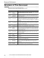
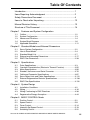
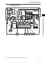
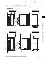
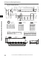
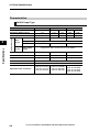
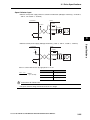
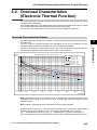
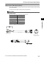
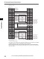
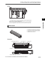
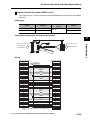
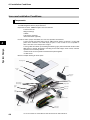
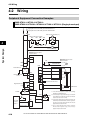
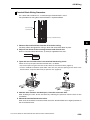
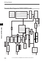
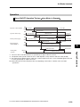
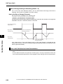
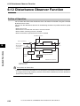
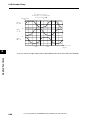
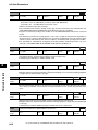
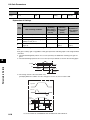
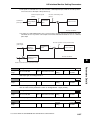
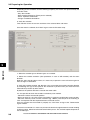
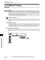
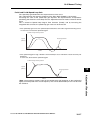
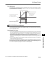
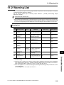
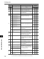
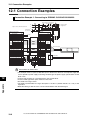
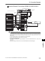
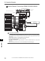
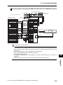
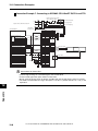
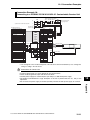
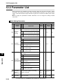
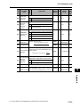
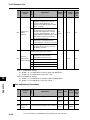
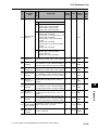
1
Cat. No. I163E-EN-01A Accurax G5-Linear Servo system with Analogue/Pulse control Model: R88D-KT@@@-L Servo Drives R88L-EC-GW-@@-@@@ Linear Servo Motors R88L-EC-FW-@@-@@@ Linear Servo Motors USER’S MANUAL Introduction Introduction Thank you for purchasing the Accurax G5-Linear. This user's manual explains how to install and wire the Accurax G5-Linear, set parameters needed to operate the G5, and remedies to be taken and inspection methods to be used if problems occur. Intended Readers This manual is intended for the following individuals. Those having electrical knowledge (certified electricians or individuals having equivalent or more knowledge) and also being qualified for one of the following: Those in charge of introducing FA equipment Those designing FA systems Those managing FA sites Notes This manual contains the information you need to know to correctly use the Accurax G5-Linear and peripheral equipment. Before using the Accurax G5-Linear, read through this manual and gain a full understanding of the information provided herein. After you finished reading the manual, keep it in a convenient place so that the manual can be referenced at any time. Make sure this manual will also get to the end-user. Accurax G5-LINEAR AC SERVOMOTOR AND SERVO DRIVE USER'S MANUAL 1 Items Requiring Acknowledgment Items Requiring Acknowledgment 1. Terms of Warranty (1) Warranty period The warranty period of this product is 1 year after its purchase or delivery to the specified location. (2) Scope of warranty If the product fails during the above warranty period due to design, material or workmanship, we will provide a replacement unit or repair the faulty product free of charge at the location where you purchased the product. Take note, however, that the following failures are excluded from the scope of warranty. a) Failure due to use or handling of the product in any condition or environment not specified in the catalog, operation manual, etc. b) Failure not caused by this product c) Failure caused by any modification or repair not carried out by OMRON d) Failure caused by any use not intended for this product e) Failure that could not be predicted with the level of science and technology available when the product was shipped from OMRON f) Failure caused by a natural disaster or any other reason for which OMRON is not held responsible Take note that this warranty applies to the product itself, and losses induced by a failure of the product are excluded from the scope of warranty. 2. Limited Liability (1) OMRON shall not assume any responsibility whatsoever for any special damage, indirect damage or passive damage arising from this product. (2) OMRON shall not assume any responsibility for programming done by individuals not belonging to OMRON, if the product is programmable, or outcomes of such programming. 3. Conditions for Intended Application (1) If this product is combined with other product, the customer must check the standards and regulations applicable to such combination. The customer must also check the compatibility of this product with any system, machinery or device used by the customer. If the above actions are not taken, OMRON shall not assume any responsibility regarding the compatibility of this product. (2) If the product is used in the following applications, consult your OMRON sales representative to check the necessary items according to the specification sheet, etc. Also make sure the product is used within the specified ratings and performance ranges with an ample margin and implement safety measures, such as designing a safety circuit, to minimize danger should the product fail. a) Used in any outdoor application, application subject to potential chemical contamination or electrical interference, or in any condition or environment not specified in the catalog, operation manual, etc. b) Nuclear power control equipment, incineration equipment, railway, aircraft and vehicle equipment, medical machinery, entertainment machinery, safety system or any other device controlled by an administrative agency or industry regulation c) System, machinery or device that may threaten human life or property d) Gas, water or electricity supply system, system operated continuously for 24 hours or any other equipment requiring high reliability e) Any other application where a high level of safety corresponding to a) to d) above is required (3) If the customer wishes to use this product in any application that may threaten human life or property, be sure to confirm beforehand that the entire system is designed in 2 Accurax G5-LINEAR AC SERVOMOTOR AND SERVO DRIVE USER'S MANUAL Items Requiring Acknowledgment such a way to notify dangers or ensure the necessary level of safety via design redundancy, and that the product is wired and installed appropriately in the system according to the intended application. (4) Sample applications explained in the catalog, etc. are provided for reference purposes only. When adopting any of these samples, check the function and safety of each equipment or device. (5) Understand all prohibited items and notes on use provided herein, so that this product will be used correctly and that customers or third parties will not suffer unexpected losses. 4. Specification Change The product specifications and accessories explained in the catalog, operation manual, etc. are subject to change, if necessary, for the reasons of improvement, etc. Contact your OMRON sales representative to check the actual specifications of this product. 5. Scope of Service The price of this product excludes costs of service such as dispatching engineers. If you have any request regarding service, consult your OMRON sales representative. Accurax G5-LINEAR AC SERVOMOTOR AND SERVO DRIVE USER'S MANUAL 3 Safety Precautions Document Safety Precautions Document So that the Accurax G5-Linear Servo Motor and Servo Drive and peripheral equipment are used safely and correctly, be sure to peruse this Safety Precautions document section and the main text before using the product in order to learn all items you should know regarding the equipment as well as all safety information and precautions. Make an arrangement so that this manual also gets to the end-user of this product. After reading this manual, keep it with you at all times. Explanation of Display The precautions explained in this section describe important information regarding safety and must be followed without fail. The display of precautions used in this manual and their meanings are explained below. Danger When an incorrect handling can lead to a dangerous situation, which may result in death or serious injury Or, when a serious property damage may occur Caution When an incorrect handling can lead to a dangerous situation, which may result in a minor or moderate injury, and when only a property damage may occur Even those items denoted by the caution symbol may lead to a serious outcome depending on the situation. Accordingly, be sure to observe all safety precautions. This symbol indicates an item you should perform or avoid in order to use the product safely. This symbol indicates an item you should perform or avoid in order to prevent inoperative, malfunction or any negative effect on performance or function. This symbol indicates an item that helps deepen your understanding of the product or other useful tip. Explanation of Symbols Example of symbols This symbol indicates danger and caution. The specific instruction is described using an illustration or text inside or near The symbol shown to the left indicates "beware of electric shock". . This symbol indicates a prohibited item (item you must not do). The specific instruction is described using an illustration or text inside or near The symbol shown to the left indicates "disassembly prohibited". . This symbol indicates a compulsory item (item that must be done). The specific instruction is described using an illustration or text inside or near The symbol shown to the left indicates "grounding required". 4 Accurax G5-LINEAR AC SERVOMOTOR AND SERVO DRIVE USER'S MANUAL . Safety Precautions Document For Safe Use of This Product Illustrations contained in this manual sometimes depict conditions without covers and safety shields for the purpose of showing the details. When using this product, be sure to install the covers and shields as specified and use the product according to this manual. If the product has been stored for an extended period of time, contact your OMRON sales representative. Danger Be sure to ground the frame ground terminals of the drive and motor to 100 or less. Electric shock may result. Never touch the parts inside the drive. Electric shock may result. While the power is supplied, do not remove the front cover, terminal covers, cables and options. Electric shock may result. Installation, operation and maintenance or inspection by unauthorized personnel is prohibited. Electric shock or injury may result. Before carrying out wiring or inspection, turn OFF the power supply and wait for at least 15 minutes. Electric shock may result. Do not damage, pull, stress strongly or pinch the cables or place heavy articles on them. Electric shock, stopping of product operation or burn damage may result. Never touch the moving part of the motor during operation. Injury may result. Never modify the product. Injury or equipment damage may result. Install a stopping device on the machine side to ensure safety. Injury may result. Install an immediate stop device externally to the machine so that the operation can be stopped and the power supply cut off immediately. Injury may result. When the power is restored after a momentary power interruption, the machine may restart suddenly. Never come close to the machine. * Implement remedies to ensure safety of people nearby even when the machine is restarted. Injury may result. After an earthquake, be sure to conduct safety checks. Electric shock, injury or fire may result. Never drive the motor using an external drive source. Fire may result. Accurax G5-LINEAR AC SERVOMOTOR AND SERVO DRIVE USER'S MANUAL 5 Safety Precautions Document Danger Do not place flammable materials near the motor, drive or Regeneration Resistor. Fire may result. Install the motor, drive and Regeneration Resistor to non-flammable materials such as metals. Fire may result. When you perform a system configuration using the safety function, be sure to fully understand the relevant safety standards and the descriptions in the operation manual, and apply them to the system design. Injury or damage may result. Do not use the cable when it is laying in oil or water. Electric shock, injury or fire may result. Never connect a commercial power supply directly to the motor. Fire or failure may result. Do not perform wiring or any operation with wet hands. Electric shock, injury or fire may result. Do not touch the motor with bare hands or place them inside the motor movable zone. Injury may result. Install a stopping device on the machine to ensure safety. The Linear Servomotor may not be maintained to be stopped when the Linear Servomotor is uncontrolled. Or, injury or equipment damage may result. Use the motor and drive in the specified combination. Fire or equipment damage may result. Caution Do not store or install the product in the following environment: Location subject to direct sunlight Location where the ambient temperature exceeds the specified level Location where the relative humidity exceeds the specified level Location subject to condensation due to the rapid temperature change Location subject to corrosive or flammable gases Location subject to higher levels of dust, salt content or iron dust Location subject to splashes of water, oil, chemicals, etc. Location where the product may receive vibration or impact directly Installing or storing the product in these locations may result in fire, electric shock or equipment damage. The drive radiator, Regeneration Resistor, motor, etc. may become hot while the power is supplied or remain hot for a while even after the power supply is cut off. Never touch these components. A burn injury may result. 6 Accurax G5-LINEAR AC SERVOMOTOR AND SERVO DRIVE USER'S MANUAL Safety Precautions Document Storage and Transportation Caution When transporting the product, do not hold it by the cables. Injury or failure may result. Do not overload the products. (Follow the instruction on the product label.) Injury or failure may result. Do not place the linear-magnet close to the motor coil or other magnetic object that may be attracted. Damage or injury may result. Magnetic sensitive objects like banking cards or other magnetic information carriers may be damaged if they are brought within 10cm of the magnet plates. Accurax G5-LINEAR AC SERVOMOTOR AND SERVO DRIVE USER'S MANUAL 7 Safety Precautions Document Installation and wiring Caution Do not step on the product or place heavy articles on it. Injury may result. Do not block the intake or exhaust openings. Do not allow foreign objects to enter the product. Fire may result. Be sure to observe the mounting direction. Failure may result. Provide the specified clearance between the drive and the inner surface of the control panel or other equipment. Fire or failure may result. Do not apply strong impact on the motor or drive. Failure may result. Wire the cables correctly and securely. Runaway motor, injury or failure may result. Securely tighten the unit mounting screws, terminal block screws and cable screws. Failure may result. Use crimp terminals for wiring. If simple twisted wires are connected directly to the protective ground terminal, fire may result. Only use the power supply voltage specified in this manual. Burn damage may result. In locations where the power supply infrastructure is poor, make sure the rated voltage can be supplied. Equipment damage may result. Provide safety measures, such as a breaker, to protect against short circuiting of external wiring. Fire may result. If the product is used in the following locations, provide sufficient shielding measures. Location where noise generates due to static electricity, etc. Location where a strong electric or magnetic field generates Location where exposure to radioactivity may occur Location where power supply lines are running nearby Using the product in these locations may result in equipment damage. Connect an immediate stop relay in series with the brake control relay. Injury or failure may result. When connecting the battery, make sure the correct polarity is connected. Battery damage or explosion may result. The magnet plates show large attraction force on all shoft magnetic objects such as iron. These forces cannot be controlled by hand. They may cause serious jamming danger. 8 Accurax G5-LINEAR AC SERVOMOTOR AND SERVO DRIVE USER'S MANUAL Safety Precautions Document Do not bring any soft magnetic objets (iron) nearer than 10cm of the magnetic side of the magnet plates. Be sure that the magnetic plates are fixed into your machine before removing the magnetic field neutralizing protection plates. Put the magnetic field neutralizing protection plates on the magnetic plates again before dismounting them. Operation and Adjustment Caution Conduct a test operation after confirming that the equipment is not affected. Equipment damage may result. Before operating the product in an actual environment, check if it operates correctly based on the parameters you have set. Equipment damage may result. Never adjust or set parameters to extreme values, as it will make the operation unstable. Injury may result. Separate the motor from the mechanical load and check its operation. Injury may result. If an alarm generated, remove the cause of the alarm and ensure safety, and then reset the alarm and restart the operation. Injury may result. Do not operate the Linear Servo Motor when an excessive load mass is installed. Failure may result. Install proper limit switches to prevent unexpected runaway of the motor. Injury or damage may result. If the drive fails, cut off the power supply to the drive on the power supply side. Fire may result. Do not turn ON and OFF the main drive power supply frequently. Failure may result. Accurax G5-LINEAR AC SERVOMOTOR AND SERVO DRIVE USER'S MANUAL 9 Safety Precautions Document Maintenance and Inspection Caution After replacing the unit, transfer to the new unit all data needed to resume operation, before restarting the operation. Equipment damage may result. Never repair the product by disassembling it. Electric shock or injury may result. Be sure to turn OFF the power supply when the unit is not going to be used for a prolonged period of time. Injury may result. Before carrying out checks or doing any maintenance, clear the system by disconnecting the voltage. Be sure that there is no possibility of accidental connections. Electric shock, injury or fire may result. 10 Accurax G5-LINEAR AC SERVOMOTOR AND SERVO DRIVE USER'S MANUAL Safety Precautions Document Location of Warning Label This product bears a warning label at the following location to provide handling warnings. When handling the product, be sure to observe the instructions provided on this label. Warning label display location (R88D-KT02H-L) Instructions on Warning Label Disposal When disposing of the battery, insulate it using tape, etc. and dispose of it by following the applicable ordinance of your local government. Dispose of the product as an industrial waste. Accurax G5-LINEAR AC SERVOMOTOR AND SERVO DRIVE USER'S MANUAL 11 Items to Check after Unpacking Items to Check after Unpacking After unpacking, check the following items. Is this the model you ordered? Is there any damage sustained during shipment? Accessories of This Product Safety Precautions document x 1 copy Connectors, mounting screws, etc. other than those in the table below are not supplied. They must be prepared by the customer. If any item is missing or a problem is found such as Servo Drive damage, contact the OMRON dealer or sales office where you purchased your product. Main power supply connector Specifications Singlephase 100 VAC Control power supply connector Motor connector Regeneration Resistor connector Open software Safety bypass connector 100 W 200 W 400 W 200 W Singlephase/3phase 200 VAC 400 W 750 W 1 kW Included 1.5 kW 3-phase 200 VAC 2 kW 600 W 1 kW 3-phase 400 VAC 1.5 kW 2 kW 3 kW 5 kW 12 Accurax G5-LINEAR AC SERVOMOTOR AND SERVO DRIVE USER'S MANUAL Included Manual Revision History Manual Revision History The manual revision symbol is an alphabet appended at the end of the manual number found in the bottom left-hand corner of the front or back cover. Example I163E-EN-01A Revision symbol Revision symbol Revision date Description of revision and revised page 01 November 2010 First Print. 01A July 2013 Page 6-61: Explanation for parameter number Pn925 and Pn926 corrected Accurax G5-LINEAR AC SERVOMOTOR AND SERVO DRIVE USER'S MANUAL 13 Structure of This Document Structure of This Document This manual consists of the following chapters. Read the necessary chapter or chapters referring to below. Outline Chapter 1 Features and System Configuration This chapter explains the features of this product, name of each part, and applicable EC directives and UL standards. Chapter 2 Standard Models and External Dimensions This chapter explains the models of Servo Drive, Linear Servo Motor, and peripheral equipment, as well as the external dimensions and mounting dimensions. Specifications This chapter explains the general specifications, characteristics, connector specifications and I/O circuits of the Servo Drive, general specifications, characteristics, encoder specifications of the Linear Servo Motor, and all other specifications including those of peripheral equipment. Chapter 4 System Design This chapter explains the installation conditions, wiring methods including wiring conforming to EMC directives and how to calculate the regenerative energy depending on Servo Drive, Linear Servo Motor and application characteristics. Chapter 5 BASIC This chapter explains an outline of operations available in various CONTROL mode CONTROL modes and explains the contents of setting. Chapter 6 Applied Functions This chapter explains different functions such as anti-vibration control, electronic-gear, gain switching and disturbance observer, and explains the contents of settings. Also explains how to setup Linear Servo Motor parameters and encoder. Chapter 7 Safety Function This function stops the motor based on a signal from a Safety Controller or safety sensor. An outline of the function is explained together with operation and connection examples. Chapter 8 Parameters Details This chapter explains the set value and contents of setting of each parameter. Chapter 9 Operation This chapter explains the operating procedures and how to operate in each mode. Chapter 10 Adjustment Functions This chapter explains the functions, setting methods and items to note regarding various gain adjustments. Chapter 3 14 Error and Chapter 11 Maintenance This chapter explains the items to check when problems occur, error diagnosis using the alarm LED display and measures, error diagnosis based on the operating condition and measures, and periodic maintenance. Chapter 12 Appendix This chapter provides connection examples using OMRON's PLC and Position Controller, as well as a list of parameters. Accurax G5-LINEAR AC SERVOMOTOR AND SERVO DRIVE USER'S MANUAL Table Of Contents Introduction ......................................................................................1 Items Requiring Acknowledgment ...................................................2 Safety Precautions Document .........................................................4 Items to Check after Unpacking.......................................................12 Manual Revision History ..................................................................13 Structure of This Document .............................................................14 Chapter 1 Features and System Configuration 1-1 1-2 1-3 1-4 1-5 Outline ................................................................................................ 1-2 System Configuration ......................................................................... 1-3 Names and Functions......................................................................... 1-4 System Block Diagrams ..................................................................... 1-6 Applicable Standards.......................................................................... 1-11 Chapter 2 Standard Models and External Dimensions 2-1 2-2 2-3 2-4 2-5 Servo System Configuration............................................................... 2-2 How to Read Model ............................................................................ 2-4 Standard Model List............................................................................ 2-7 External and Mounting Dimensions.................................................... 2-17 EMC Filter Dimensions....................................................................... 2-39 Chapter 3 Specifications 3-1 3-2 3-3 3-4 3-5 3-6 3-7 3-8 Drive Specifications ............................................................................ 3-3 Overload Characteristics (Electronic Thermal Function) .................... 3-55 Motor Specifications ........................................................................... 3-56 Encoder, Hall sensor and Serial Converter ........................................ 3-76 Cable and Connector Specifications .................................................. 3-87 Servo Relay Units and Cable Specifications ...................................... 3-112 External Regeneration Resistor Specifications .................................. 3-130 EMC Filter Specifications ................................................................... 3-132 Chapter 4 System Design 4-1 4-2 4-3 4-4 Installation Conditions ........................................................................ 4-2 Wiring ................................................................................................. 4-16 Wiring Conforming to EMC Directives ................................................ 4-30 Regenerative Energy Absorption........................................................ 4-44 Chapter 5 BASIC CONTROL Mode 5-1 5-2 5-3 5-4 5-5 Position Control .................................................................................. 5-2 Speed Control..................................................................................... 5-8 Force Control...................................................................................... 5-14 Internally Set Speed Control............................................................... 5-19 Switching Control................................................................................ 5-22 Accurax G5-LINEAR AC SERVOMOTOR AND SERVO DRIVE USER'S MANUAL 15 Table Of Contents Chapter 6 Applied Functions 6-1 6-2 6-3 6-4 6-5 6-6 6-7 6-8 6-9 6-10 6-11 6-12 6-13 6-14 6-15 6-16 6-17 6-18 6-19 6-20 Anti-vibration Control .......................................................................... 6-3 Adaptive Filter..................................................................................... 6-7 Notch Filter ......................................................................................... 6-9 Electronic Gear Function .................................................................... 6-12 Encoder Dividing Function.................................................................. 6-14 Brake Interlock.................................................................................... 6-18 Gain Switching Function..................................................................... 6-23 Gain Switching 3 Function.................................................................. 6-31 Force Limit.......................................................................................... 6-32 Sequence I/O Signal........................................................................... 6-35 Forward and Reverse Drive Prohibition Functions ............................. 6-41 Disturbance Observer Function.......................................................... 6-44 Friction Force Compensation Function............................................... 6-46 Mass Ratio Switching Function .......................................................... 6-48 Feed-forward Function ....................................................................... 6-49 Instantaneous Speed Observer Function ........................................... 6-53 Motor Setup ........................................................................................ 6-55 Encoder Setup.................................................................................... 6-58 Magnetic Pole Position ....................................................................... 6-61 Setup with Serial Converter................................................................ 6-64 Chapter 7 Safety Function 7-1 7-2 7-3 Safe Force OFF (STO) Function ........................................................ 7-2 Operation Example............................................................................. 7-5 Connection Example .......................................................................... 7-7 Chapter 8 Parameters Details 8-1 8-2 8-3 8-4 8-5 8-6 8-7 8-8 Basic Parameters ............................................................................... 8-2 Gain Parameters ................................................................................ 8-9 Vibration Suppression Parameters..................................................... 8-20 Analog Control Parameters ................................................................ 8-25 Interface Monitor Setting Parameters................................................. 8-35 Extended Parameters......................................................................... 8-45 Special Parameters ............................................................................ 8-57 Linear Motor And Encoder Setting Parameters............................... 8-62 Chapter 9 Operation 9-1 9-2 9-3 9-4 9-5 16 Operational Procedure ....................................................................... 9-2 Preparing for Operation ...................................................................... 9-3 Using the Front Display ...................................................................... 9-10 Setting the Mode ................................................................................ 9-11 Trial Operation.................................................................................... 9-35 Accurax G5-LINEAR AC SERVOMOTOR AND SERVO DRIVE USER'S MANUAL Table Of Contents Chapter 10 Adjustment Functions 10-1 Gain Adjustment ................................................................................. 10-2 10-2 Realtime Autotuning ........................................................................... 10-4 10-3 Manual Tuning.................................................................................... 10-12 Chapter 11 Error and Maintenance 11-1 11-2 11-3 11-4 11-5 Error Processing................................................................................. 11-2 Warning List........................................................................................ 11-5 Alarm List............................................................................................ 11-6 Troubleshooting.................................................................................. 11-11 Periodic Maintenance ......................................................................... 11-23 Chapter 12 Appendix 12-1 Connection Examples......................................................................... 12-2 12-2 Parameter List .................................................................................... 12-12 12-3 Safety Certification ............................................................................. 12-37 Index Accurax G5-LINEAR AC SERVOMOTOR AND SERVO DRIVE USER'S MANUAL 17 18 Features and System Configuration This chapter explains the features of this product, name of each part, and applicable EC directives and UL standards. 1-1 Outline ...........................................................................1-2 Outline of the Accurax G5-Linear.................................................... 1-2 Features of the Accurax G5-Linear................................................. 1-2 1-2 System Configuration ..................................................1-3 1-3 Names and Functions ..................................................1-4 Drive Part Names............................................................................ 1-4 Drive Functions ............................................................................... 1-5 1-4 System Block Diagrams...............................................1-6 1-5 Applicable Standards .................................................1-11 EC Directives ................................................................................ 1-11 UL and cUL Standards.................................................................. 1-11 Functional Safety .......................................................................... 1-11 Accurax G5-LINEAR AC SERVOMOTOR AND SERVO DRIVE USER'S MANUAL 1 1-1 Outline 1-1 Outline Outline of the Accurax G5-Linear With the Accurax G5-Linear, you can perform position, speed and Force control. 2 linear motor families with various models are available for a wide range of forces. Drives with supplies of 100V, 200V or 400V depending on the required maximum speed available. You will surely find a model that best suits your application. Features and System Configuration 1 The Accurax G5-Linear features realtime autotuning function and adaptive filter function that automatically perform complex gain adjustments. A notch filter can also be automatically set to suppress machine vibration by reducing machine resonance during operation. The anti-vibration control function of the Linear Servo Drive realizes stable stopping performance in a mechanism witch vibrates beacuse of the low rigidity of the load. Features of the Accurax G5-Linear The Accurax G5-Linear has the following features. 6 Possible CONTROL modes Switching You can switch among 6 CONTROL modes including the following: (1) position control, (2) speed control, (3) force control, (4) position and speed control, (5) position and force control, (6) speed and force control. Desired modes can be selected in the drive according to your need. A single drive support different modes. Two motor families to Match Any Necessity The Accurax G5-Linear servomotors have two families. G-family for the highest acceleration & low-medium force application and F-family for the high speed and wide force range application. Safe Force OFF (STO) Function to Ensure Safety You can cut off the motor current to stop the motor based on a signal from an immediate stop button or other safety equipment. In addition to the conventional stop method based on a control signal, the STO function that permits direct stopping without a need to involve the control circuit provides the immediate stop from 2 systems, thereby enhancing safety. Wide Range of Power Supplies to Match Any maximum speed The same Accurax G5-Linear servomotor can be controlled with a servodrive of 100V, 200V or 400V in order to reach different maximum speeds (see the Velocity-Force curves of each motor). 1-2 Accurax G5-LINEAR AC SERVOMOTOR AND SERVO DRIVE USER'S MANUAL 1-2 System Configuration 1-2 System Configuration Controller (Voltage Output Type) Analog voltage Programmable Controller SYSMAC CS 1 Motion Control Unit CS1W-MC221/421 (-V1) Features and System Configuration Pulse train 'Accurax G5-Linear AC Servomotor R88D-KTx SYSMAC + Position Control Unit (Pulse Train Output Type) NC414 CN1 CN2 RUN SYNC 1 A1 B1 PA202 POWER SYSMAC CJ1G-CPU44 2 A2 B2 ERC ERH 3 A3 B3 4 A4 B4 AS BS RUN ERR/ALM INH PRPHL PROGRAMMABLE CONTROLLER COMM OPEN MACH No. x10 1 AXIS1 L1 MCPWR BUSY AC100 -240V INPUT L2/N CN3 CN4 x10 0 AXIS2 NC AXIS1 AXIS2 PERIPHERAL NC PORT Programmable Controller SYSMAC CJ/CS Position Control Unit CJ1W-NC113/213/413 CJ1W-NC133/233/433 CJ1W-NC214/414 CJ1W-NC234/434 CS1W-NC113/213/413 CS1W-NC133/233/433 C200HW-NC113/213/413 Accurax G5-LINEAR AC SERVOMOTOR AND SERVO DRIVE USER'S MANUAL 'Accurax G5-Linear AC Servomotor R88L-EC-FW R88L-EC-GW 1-3 1-3 Names and Functions 1-3 Names and Functions Drive Part Names Display area 1 Monitor connector (CN5) Features and System Configuration Operation area USB connector (CN7) Expansion connector (CN3) Main circuit power supply terminals (L1, L2, and L3) Safety connector (CN8) Control circuit power supply terminals (L1C and L2C) Charge lamp Control I/O connector (CN1) External Regeneration Resistor connection terminals (B1, B2 and B3) Motor connection terminals (U, V and W) External scale connector (CN4) Protective ground terminals 1-4 Not used (CN2) Accurax G5-LINEAR AC SERVOMOTOR AND SERVO DRIVE USER'S MANUAL 1-3 Names and Functions Drive Functions Display Area A 6-digit 7-segment LED display shows the drive status, alarm codes, parameters, and other information. 1 Operation Area Monitors the parameter setting and drive condition. Features and System Configuration Charge Lamp Lits when the main circuit power supply is turned ON. Control I/O Connector (CN1) Used for command input signals and I/O signals. Not used (CN2) This connector is not used in the Accurax G5-Linear servodrive. Expansion Connector (CN3) A spare connector for expansion. Do not connect anything. External Scale Connector (CN4) Connector for the external linear encoder (if A/B type is used) or the Serial Converter (if SINCOS type is used). Monitor Connector (CN5) 2 analog outputs to monitor values like motor movement speed, force command value, etc. USB Connector (CN7) Communications connector for the computer. Safety Connector (CN8) Connector for the safety devices. If no safety device is used, keep the factory-set safety bypass connector installed. Accurax G5-LINEAR AC SERVOMOTOR AND SERVO DRIVE USER'S MANUAL 1-5 1-4 System Block Diagrams 1-4 System Block Diagrams Size A: R88D-KT01L-L/-02H-L Size B: R88D-KT02L-L/-04H-L L1 Features and System Configuration B1 B2 + FUSE L2 1 CN B CN A FUSE L3 B3 − L1C FUSE L2C U V W Voltage detection + − GR GR 1-6 15 V G1 SW power supply main circuit control 5V 3.3 V 2.5 V 1.5 V E5 V ±12 V G2 Internal control power supply Relay drive Regeneration control Overcurrent detection Current detection Gate drive Display and setting circuit area MPU&ASIC Position, speed and force calculation control area • PWM control CN1 CN4 CN5 CN7 CN8 Control interface External scale Analog monitor USB Safety Accurax G5-LINEAR AC SERVOMOTOR AND SERVO DRIVE USER'S MANUAL 1-4 System Block Diagrams Size C: R88D-KT04L-L/-08H-L Size D: R88D-KT10H-L/-15H-L CN B CN A FUSE L1 B1 B2 + B3 Internal Regeneration Resistor L2 FUSE L3 − L1C FUSE Voltage detection + 1 − GR GR 15 V G1 SW power supply main circuit control 5V 3.3 V 2.5 V 1.5 V E5 V ±12 V G2 Internal control power supply Relay drive Regeneration control Overcurrent detection Current detection Gate drive Display and setting circuit area MPU&ASIC Position, speed and force calculation control area • PWM control Cooling fan CN1 CN4 CN5 CN7 CN8 Control interface External scale Analog monitor USB Safety Accurax G5-LINEAR AC SERVOMOTOR AND SERVO DRIVE USER'S MANUAL 1-7 Features and System Configuration L2C U V W 1-4 System Block Diagrams Size D: R88D-KT06F-L/-10F-L/-15F-L L1 CN D CN A FUSE B1 B2 + Internal Regen Resistor L2 B3 N L3 1 FUSE Fuse (not installed) − CN B CN C 24V FUSE 0V U V W Voltage detection + + DC-DC − − Features and System Configuration GR 15 V G1 SW power supply main circuit control 5V 3.3 V 2.5 V 1.5 V E5 V ±12 V G2 Internal control power supply Relay drive Regeneration control Overcurrent detection Current detection Gate drive Display and setting circuit area MPU&ASIC Position, speed and force calculation control area • PWM control Cooling fan 1-8 CN1 CN4 CN5 CN7 CN8 Control interface External scale Analog monitor USB Safety Accurax G5-LINEAR AC SERVOMOTOR AND SERVO DRIVE USER'S MANUAL 1-4 System Block Diagrams Size E: R88D-KT20H-L CN C CN A FUSE L1 B1 B2 + Internal Regen Resistor L2 B3 N Fuse (not installed) FUSE L3 − L1C FUSE L2C CN B Voltage detection + U V W 1 GR GR 15 V G1 SW power supply main circuit control 5V 3.3 V 2.5 V 1.5 V E5 V ±12 V G2 Internal control power supply Relay drive Regeneration control Overcurrent detection Current detection Gate drive Display and setting circuit area MPU&ASIC Position, speed and force calculation control area • PWM control Cooling fan CN1 CN4 CN5 CN7 CN8 Control interface External scale Analog monitor USB Safety Accurax G5-LINEAR AC SERVOMOTOR AND SERVO DRIVE USER'S MANUAL 1-9 Features and System Configuration − 1-4 System Block Diagrams Size E: R88D-KT20F-L Size F: R88D-KT30F-L/-50F-L L1 CN D CN A FUSE B1 B2 + Internal Regen Resistor L2 B3 N L3 1 FUSE − CN B CN C 24V Features and System Configuration Fuse (not installed) FUSE 0V U V W Voltage detection + + DC-DC − − GR 15 V G1 SW power supply main circuit control 5V 3.3 V 2.5 V 1.5 V E5 V ±12 V G2 Internal control power supply Relay drive Regeneration control Overcurrent detection Current detection Gate drive Display and setting circuit area MPU&ASIC Position, speed and force calculation control area • PWM control Cooling fan 1-10 CN1 CN4 CN5 CN7 CN8 Control interface External scale Analog monitor USB Safety Accurax G5-LINEAR AC SERVOMOTOR AND SERVO DRIVE USER'S MANUAL 1-5 Applicable Standards 1-5 Applicable Standards EC Directives EC directive Low voltage directive Product Applicable standards AC Linear Servo Drive EN 61800-5-1 AC Linear Servomotor EN 60034-1: 2004 1 EMC directives AC Linear Servo Drive EN 55011 class A group 1 IEC61800-3 EN61000-6-2 Note. To conform to EMC directives, the Linear Servo Motor and Servo Drive must be installed under the conditions described in "4-3 Wiring Conforming to EMC Directives" (P.4-30). UL and cUL Standards Standard Product Applicable standards File number UL standards AC Linear Servo Drive UL508C E179149 CSA standards AC Linear Servo Drive CSA22.2 No. 14 E179149 All components in the linear motors are UL certified. Functional Safety Standard Functional safety Product AC Linear Servo Drive Applicable standards EN954-1 (Category 3) ISO13849-1 (Performance level D) EN61508 (SIL2) EN62061 (SIL2) EV61800-5-2 (STO) IEC61326-3-1 (SIL2) Accurax G5-LINEAR AC SERVOMOTOR AND SERVO DRIVE USER'S MANUAL 1-11 Features and System Configuration EN 60204-1: 2006 Standard Models and External Dimensions 2 This chapter explains the models of Servo Drive, Linear Servo Motor, and peripheral equipment, as well as the external dimensions and mounting dimensions. 2-1 Servo System Configuration .......................................2-2 2-2 How to Read Model.......................................................2-4 Linear Servo Drive .......................................................................... 2-4 Linear Servomotor .......................................................................... 2-5 2-3 Standard Model List .....................................................2-7 Linear Servo Drive Model List......................................................... 2-7 Linear Servomotor Model List ......................................................... 2-8 Linear Servo Drive and Servomotor Combination List.................... 2-9 Peripheral Equipment and Cable Model List................................. 2-11 2-4 External and Mounting Dimensions..........................2-17 Linear Servo Drive Dimensions .................................................... 2-17 Linear Servomotor Dimensions..................................................... 2-27 External Regeneration Resistor Dimensions ................................ 2-38 2-5 EMC Filter Dimensions...............................................2-39 Accurax G5-LINEAR AC SERVOMOTOR AND SERVO DRIVE USER'S MANUAL 2-1 Servo System Configuration 2-1 Servo System Configuration Support Software •CX-One Software Package Controller (Including CX-Drive, CX-MotionPro, CX-Motion, CX-Programmer) High-speed type NC414 CN1 CN2 RUN SYNC 1 A1 B1 SYSMAC CJ2H CPU64 ERC 2 A2 B2 ERH 3 A3 B3 4 A4 B4 AS BS RUN ERR/ALM INH PRPHL PROGRAMMABLE CONTROLLER COMM BKUP OPEN MACH No. x10 1 AXIS1 MCPWR BUSY x10 0 CN3 CN4 PERIPHERAL AXIS2 Direct connection cable for CJ1W-NC@@4 AXIS1 PORT Connector Terminal Block Conversion Unit XW2[]-20G[] External Signal AXIS2 NC113 01 MACH 2 3 No. 10 1 23 789 INH PRPHL PROGRAMMABLE CONTROLLER RUN ERC ERH 4 56 RUN ERR/ALM 01 X SYSMAC CJ1G-CPU44 10 0 COMM 20 OPEN 20 Position Control Unit Cable (NC) PORT XW2Z-[]-A[] CN1 PERIFHERAL Pulse Train Commands Position Control Unit Cable XW2Z-[]X MCPWR BUSY 1 Servo Relay Unit XW2B-[] Servo Drive Cable XW2Z-[]-B[] 1 X Programmable Controller SYSMAC CJ1/CS1 Position Control Unit (NC) CJ1W-NC[][]3 CS1W-NC[][]3 C200HW-NC[][]3 External Signal CPU Unit Built-in pulse I/O function type CJ1M-CPU2[] Connector-Terminal Block Conversion Units and Cable XW2[]-50G[] Built-in pulse I/O function type XW2Z-[][][]J-B24 Pulse Train Commands CP1H/CP1L Analog Commands Standard Models and External Dimensions Pulse Train Commands/Feedback Signals Standard type 4 56 Position Control Unit Position Control Unit (NC) CJ1W-NC214/414 CJ1W-NC234/434 7 89 2 Programmable Controller SYSMAC CJ2 USB commu XW2Z-[][][]J-G[] 2-2 SYSMAC + Controller (Analog output type) Control Cables (for Motion Control Unit) R88A-CPG Programmable Controller SYSMAC CS1 Analog Commands/Feedback Signals Motion Control Unit (MC) CS1W-MC221/421 (-V1) Accurax G5-LINEAR AC SERVOMOTOR AND SERVO DRIVE USER'S MANUAL 2-1 Servo System Configuration munications Linear Servo Drive with A/B pulse encoder Motor power signals AC Linear Servomotors with A/B pulse encoder 2 Power Cables • Standard Cables R88A-CAWK[][][]S-DE Encoder Cables • Standard Cables R88A-CRKN[][][]CR-E R88D-KT or with SinCos encoder Standard Models and External Dimensions • Accurax G5-Linear motor • Accurax G5-Linear drive Feedback Signals A/B encoder Motor power signals R88L-EC-FW R88L-EC-GW or with SinCos encoder Power Cables • Standard Cables R88A-CAWK[][][]S-DE Encoder Cables • Standard Cables R88A-CFKA[][][]CR-E Serial converter Hall sensor Temp. sensor • Accurax G5-Linear drive SinCos encoder R88D-KT • Accurax G5-Linear motor R88L-EC-FW R88L-EC-GW Feedback Signals SinCos encoder Peripheral Devices External Regeneration Resistors R88A-RR Accurax G5-LINEAR AC SERVOMOTOR AND SERVO DRIVE USER'S MANUAL 2-3 2-2 How to Read Model 2-2 How to Read Model Linear Servo Drive The Linear Servo Drive model can be identified by the Linear Servo Drive type, applicable Linear Servomotor capacity, power supply voltage, etc. R88D-KT02H-L 2 Accurax G5-Linear Series Servomotor Drive Type T : Pulse/analog type Standard Models and External Dimensions Capacity 01 : 100 W 02 : 200 W 04 : 400 W 06 : 600 W 08 : 800 W 10 : 1 kW 15 : 1.5 kW 20 : 2 kW 30 : 3 kW 50 : 5 kW Power Supply Voltage L : 100 VAC H : 200 VAC F : 400 VAC Linear type drive 2-4 Accurax G5-LINEAR AC SERVOMOTOR AND SERVO DRIVE USER'S MANUAL 2-2 How to Read Model Linear Servomotor Iron-core family Linear motor coil R88L-EC-FW-0303-ANPC Accurax Linear Motor Component Iron-core model 2 03: 30mm active magnet width 06: 60mm active magnet width 11: 110mm active magnet width Standard Models and External Dimensions 03: 3-coil model 06: 6-coil model 09: 9-coil model 12: 12-coil model 15: 15-coil model A Version NP: No connectors PL: With connectors C: Compact Magnet track R88L-EC-FM-03xxx-A Accurax Linear Motor Component Iron-core magnet tracks 03: 30mm active magnet width 06: 60mm active magnet width 11: 110mm active magnet width Length of magnet track in mm A Version Hall sensor R88L-EC-FH-NNNN-A Accurax Linear Motor Component Digital hall-sensor for F-series Placeholder Placeholder A Version Accurax G5-LINEAR AC SERVOMOTOR AND SERVO DRIVE USER'S MANUAL 2-5 2-2 How to Read Model Ironless family Linear motor coil R88L-EC-GW-0303-ANPS Accurax Linear Motor Component Ironless coil 03: 30mm active magnet width 05: 50mm active magnet width 07: 70mm active magnet width 2 03: 3-coil model 06: 6-coil model 09: 9-coil model A Version Standard Models and External Dimensions NP: No connectors PL: With connectors S: Standard Magnet track R88L-EC-GM-03xxx-A Accurax Linear Motor Component Ironless magnet yoke 03: 30mm active magnet width 05: 50mm active magnet width 07: 70mm active magnet width Length of magnet track in mm A Version Hall sensor R88L-EC-GH-03NN-A Accurax Linear Motor Component Digital hall-sensor for G-series 03: 30mm active magnet width 05: 50mm active magnet width 07: 70mm active magnet width Placeholder A Version 2-6 Accurax G5-LINEAR AC SERVOMOTOR AND SERVO DRIVE USER'S MANUAL 2-3 Standard Model List 2-3 Standard Model List Linear Servo Drive Model List Specifications Single-phase 100 VAC Model R88D-KT01L-L 200 W R88D-KT02L-L 400 W R88D-KT04L-L 200 W R88D-KT02H-L 400 W R88D-KT04H-L 800 W R88D-KT08H-L 1 kW R88D-KT10H-L 1.5 kW R88D-KT15H-L 3-phase 200 VAC 2 kW R88D-KT20H-L 3-phase 400 VAC 600W R88D-KT06F-L 1 kW R88D-KT10F-L 1.5 kW R88D-KT15F-L 2 kW R88D-KT20F-L 3 kW R88D-KT30F-L 5 kW R88D-KT50F-L Single-phase/3-phase 200 VAC Accurax G5-LINEAR AC SERVOMOTOR AND SERVO DRIVE USER'S MANUAL 2 Standard Models and External Dimensions 100 W 2-7 2-3 Standard Model List Linear Servomotor Model List Iron-core linear servomotor model list Standard Models and External Dimensions 2 Coil with connectors Nominal Peak force force (N) (N) R88L-EC-FW-0303-ANPC R88L-EC-FW-0303-APLC 48 105 R88L-EC-FW-0306-ANPC R88L-EC-FW-0306-APLC 96 210 R88L-EC-FW-0606-ANPC R88L-EC-FW-0606-APLC 160 400 R88L-EC-FW-0609-ANPC R88L-EC-FW-0609-APLC 240 600 R88L-EC-FW-0612-ANPC R88L-EC-FW-0612-APLC 320 800 R88L-EC-FW-1112-ANPC R88L-EC-FW-1112-APLC 608 1600 R88L-EC-FW-1115-ANPC R88L-EC-FW-1115-APLC 760 2000 Magnet track R88L-EC-FM-03096-A R88L-EC-FM-03144-A R88L-EC-FM-03384-A R88L-EC-FM-06192-A R88L-EC-FM-06288-A R88L-EC-FM-11192-A R88L-EC-FM-11288-A Hall sensor R88L-EC-FH-NNNN-A Coil without connectors Ironless linear servomotor model list Coil without connectors Coil with connectors Nominal Peak force force (N) (N) R88L-EC-GW-0303-ANPS R88L-EC-GW-0303-APLS 26,5 100 R88L-EC-GW-0306-ANPS R88L-EC-GW-0306-APLS 53 200 R88L-EC-GW-0309-ANPS R88L-EC-GW-0309-APLS 80 300 R88L-EC-GW-0503-ANPS R88L-EC-GW-0503-APLS 58 240 R88L-EC-GW-0506-ANPS R88L-EC-GW-0506-APLS 117 480 R88L-EC-GW-0509-ANPS R88L-EC-GW-0509-APLS 175 720 R88L-EC-GW-0703-ANPS R88L-EC-GW-0703-APLS 117 700 R88L-EC-GW-0706-ANPS R88L-EC-GW-0706-APLS 232 1400 R88L-EC-GW-0709-ANPS R88L-EC-GW-0709-APLS 348 2100 2-8 Magnet track Hall sensor R88L-EC-GM-03090-A R88L-ECR88L-EC-GM-03120-A GH-03NN-A R88L-EC-GM-03390-A R88L-EC-GM-05126-A R88L-EC-GM-05546-A R88L-ECR88L-EC-GM-05168-A GH-05NN-A R88L-EC-GM-05210-A R88L-EC-GM-07114-A R88L-ECR88L-EC-GM-07171-A GH-07NN-A R88L-EC-GM-07456-A Accurax G5-LINEAR AC SERVOMOTOR AND SERVO DRIVE USER'S MANUAL 2-3 Standard Model List Linear Servo Drive and Servomotor Combination List The tables in this section show the optimum combination of Accurax G5-Linear Servo Drives and Servomotors. The selection is based in matching the nominal and peak current of the motor with the minimum switching frequency (6KHz or 12KHz depending on the drive). Other non optimum combination are possible for: - Using higher PWM frequency (results in a bigger drive). - Reduce the drive size in the maximum peak force of the motor is not needed. - Oversize the drive. Refer to the CX-Drive for the complete combination list. 2 Iron-core family Motor R88L-EC-FW-0306 R88L-EC-FW-0606 R88L-EC-FW-0609 R88L-EC-FW-0612 R88L-EC-FW-1112 R88L-EC-FW-1115 Drive PWM frequency (KHz) Max. speed (m/s) 100 R88D-KT01L-L 12 2,5 200 R88D-KT02H-L 12 5 400 R88D-KT06F-L 6 10 100 R88D-KT02L-L 6 2,5 200 R88D-KT04H-L 6 5 400 R88D-KT10F-L 6 10 100 R88D-KT04L-L 6 2 200 R88D-KT08H-L 6 4 400 R88D-KT15F-L 6 8 100 Not match - 2 200 R88D-KT10H-L 6 4 400 R88D-KT20F-L 6 8 100 Not match - 2 200 R88D-KT15H-L 6 4 400 R88D-KT30F-L 6 8 100 Not match - 1 200 R88D-KT15H-L 6 2 400 R88D-KT30F-L 6 4 100 Not match - 1 200 R88D-KT15H-L 6 2 400 R88D-KT30F-L 6 4 Accurax G5-LINEAR AC SERVOMOTOR AND SERVO DRIVE USER'S MANUAL Standard Models and External Dimensions R88L-EC-FW-0303 Voltage (V) 2-9 2-3 Standard Model List Ironless family Motor R88L-EC-GW-0303 R88L-EC-GW-0306 R88L-EC-GW-0309 2 R88L-EC-GW-0503 Standard Models and External Dimensions R88L-EC-GW-0506 R88L-EC-GW-0509 R88L-EC-GW-0703 R88L-EC-GW-0706 R88L-EC-GW-0709 2-10 Voltage (V) Drive PWM frequency (KHz) Max. speed (m/s) 100 R88D-KT01L-L 12 8 200 R88D-KT02H-L 12 16 100 R88D-KT04L-L 6 8 200 R88D-KT08H-L 6 16 100 Not match - 8 200 R88D-KT10H-L 6 16 100 R88D-KT01L-L 12 2,2 200 R88D-KT02H-L 12 4,4 100 R88D-KT02L-L 6 2,2 200 R88D-KT04H-L 6 4,4 100 R88D-KT04L-L 6 2,2 200 R88D-KT08H-L 6 4,4 100 R88D-KT02L-L 6 1,2 200 R88D-KT04H-L 6 2,4 100 R88D-KT04L-L 6 1,2 200 R88D-KT08H-L 6 2,4 100 Not match - 1,2 200 R88D-KT10H-L 6 2,4 Accurax G5-LINEAR AC SERVOMOTOR AND SERVO DRIVE USER'S MANUAL 2-3 Standard Model List Peripheral Equipment and Cable Model List Encoder Cable (A/B Encoder) From Encoder connector (DB-15 male with Numerik jena pinout) to CN4 connector in servodrive. Specifications For Iron-core and Ironless linear motors with connectors Model 1.5 m R88A-CRKN001-5CR-E 3m R88A-CRKN003CR-E 5m R88A-CRKN005CR-E 10 m R88A-CRKN010CR-E 15 m R88A-CRKN015CR-E 20 m R88A-CRKN020CR-E 2 From Encoder connector (DB-15 male with Numerik jena pinout) to CN4 connector in Serial Converter. Specifications For Iron-core and Ironless linear motors with connectors Model 1.5 m R88A-CFKA001-5CR-E 3m R88A-CFKA003CR-E 5m R88A-CFKA005CR-E 10 m R88A-CFKA010CR-E 15 m R88A-CFKA015CR-E Motor power cable Specifications For Iron-core linear motors with connectors For Ironless linear motors with connectors Accurax G5-LINEAR AC SERVOMOTOR AND SERVO DRIVE USER'S MANUAL Model 1.5 m R88A-CAWK001-5S-DE 3m R88A-CAWK003S-DE 5m R88A-CAWK005S-DE 10 m R88A-CAWK010S-DE 15 m R88A-CAWK015S-DE 20 m R88A-CAWK020S-DE 1.5 m R88A-CAWB001-5S-DE 3m R88A-CAWB003S-DE 5m R88A-CAWB005S-DE 10 m R88A-CAWB010S-DE 15 m R88A-CAWB015S-DE 20 m R88A-CAWB020S-DE 2-11 Standard Models and External Dimensions Encoder Cable (SinCos Encoder) 2-3 Standard Model List e Serial Converter The Serial Converter is an interface that is necessary when we want to connect to the servodrive either SinCos Encoder, hall sensor or temperature sensor. The use of the SinCos with the Serial Converter is mandatory, the use of hall sensor or temperature sensor is optional. Specifications 2 Model Serial Converter Unit from 1Vpp to G5 Serial Converter data transmission (With KTY sensor detection of Iron-core motor coil) R88A-SC01K-E Serial Converter Unit from 1Vpp to G5 Serial Converter data transmission (With NTC sensor detection of Ironless motor coil) R88A-SC02K-E Serial Converter cable From Serial Converter CN1 connector to servodrive CN4 connector. Specifications Standard Models and External Dimensions For Iron-core and Ironless linear motors with connectors Model 1.5 m R88A-CRKN001-5CR-E 3m R88A-CRKN003CR-E 5m R88A-CRKN005CR-E 10 m R88A-CRKN010CR-E 15 m R88A-CRKN015CR-E 20 m R88A-CRKN020CR-E Hall and temperature sensors cable to serial converter Specifications Extension cable from Hall and Temperature sensors to Serial Converter. (Connector DB-9) (This extension cable is optional) Model 1.5 m R88A-CFKB001-5CR-E 3m R88A-CRKB003CR-E 5m R88A-CRKB005CR-E 10 m R88A-CRKB010CR-E 15 m R88A-CRKB015CR-E 20 m R88A-CRKB020CR-E Analog Monitor Cable From CN5 connector to flat cables. Specifications Analog monitor cable 2-12 Model 1m R88A-CMK001S Accurax G5-LINEAR AC SERVOMOTOR AND SERVO DRIVE USER'S MANUAL 2-3 Standard Model List Connectors Specifications Model Linear Servo Drive external encoder connector (CN4) R88A-CNK41L Female connector for Hall and Temperature sensors 9 pin D-Sub female (Serial Converter side) Male connector for Hall and Temperature sensors 9 pin D-Sub male (Motor side) Female connector for SinCos 15 pin low density D-Sub female (Serial Converter side) Male connector for SinCos 15 pin low density D-Sub male (Encoder side) Hypertac power cable connector IP67 for Iron-core linear motors LPRA-06B-FRBN170 Hypertac power cable connector IP67 for Ironless linear motors SPOC06KFSDN169 Specifications Servo Relay Unit Model For CS1W-NC113/-NC133 For CJ1W-NC113/-NC133 For C200HW-NC113 XW2B-20J6-1B For CS1W-NC213/-NC413/-NC233/-NC433 For CJ1W-NC213/-NC413/-NC233/-NC433 For C200HW-NC213/-NC413 XW2B-40J6-2B For CJ1M-CPU21/-CPU22/-CPU23 XW2B-20J6-8A XW2B-40J6-9A For CQM1-CPU43-V1 For CQM1H-PLB21 XW2B-20J6-3B Accurax G5-LINEAR AC SERVOMOTOR AND SERVO DRIVE USER'S MANUAL Standard Models and External Dimensions Servo Relay Units (for CN1) 2 2-13 2-3 Standard Model List Servo Relay Unit Cables for Linear Servo Drives Specifications Servo Drive cables Model For CS1W-NC113/-NC133, CJ1W-NC113/NC133, C200HW-NC113 (XW2B-20J6-1B) For CS1W-NC213/-NC413/-NC233/-NC433, CJ1W-NC213/-NC413/-NC233/-NC433, C200HW-NC213/-NC413 (XW2B-40J6-2B) For CQM1-CPU43-V1 or CQM1H-PLB21 (XW2B-20J6-3B) 1m For CJM1-CPU21/-CPU22/-CPU23 (XW2B-20J6-8A/XW2B-40J6-9A) 1m XW2Z-100J-B31 2m XW2Z-200J-B31 2 XW2Z-100J-B25 XW2Z-200J-B25 2m Standard Models and External Dimensions Servo Relay Unit Cables for Position Control Units Specifications For CQM1H-PLB21 (XW2B-20J6-3B) 0.5 m XW2Z-050J-A3 1m XW2Z-100J-A3 For CS1W-NC113, C200HW-NC113 (XW2B20J6-1B) 0.5 m XW2Z-050J-A6 1m XW2Z-100J-A6 For CS1W-NC213/-NC413, C200HW-NC213/NC413 (XW2B-20J6-2B) 0.5 m XW2Z-050J-A7 1m XW2Z-100J-A7 For CS1W-NC133 (XW2B-20J6-1B) 0.5 m XW2Z-050J-A10 1m XW2Z-100J-A10 0.5 m XW2Z-050J-A11 1m XW2Z-100J-A11 0.5 m XW2Z-050J-A14 1m XW2Z-100J-A14 0.5 m XW2Z-050J-A15 1m XW2Z-100J-A15 0.5 m XW2Z-050J-A18 1m XW2Z-100J-A18 0.5 m XW2Z-050J-A19 1m XW2Z-100J-A19 0.5 m XW2Z-050J-A33 1m XW2Z-100J-A33 For CS1W-NC233/-NC433 (XW2B-20J6-2B) Position Control Unit cables For CJ1W-NC113 (XW2B-20J6-1B) For CJ1W-NC213/-NC413 (XW2B-20J6-2B) For CJ1W-NC133 (XW2B-20J6-1B) For CJ1W-NC233/-NC433 (XW2B-20J6-2B) For CJ1M-CPU21/-CPU22/-CPU23 (XW2B20J6-8A/XW2B-40J6-9A) 2-14 Model Accurax G5-LINEAR AC SERVOMOTOR AND SERVO DRIVE USER'S MANUAL 2-3 Standard Model List Control Cables Specifications Model Specified cables for Position Control Unit (line-drive output for 1 axis) CJ1W-NC234/-NC434 XW2Z-100J-G9 5m XW2Z-500J-G9 10 m XW2Z-10MJ-G9 Specified cables for Position Control Unit (open collector output for 1 axis) CJ1W-NC214/-NC414 1m XW2Z-100J-G13 3m XW2Z-300J-G13 Specified cables for Position Control Unit (line-drive output for 2 axes) CJ1W-NC234/-NC434 1m XW2Z-100J-G13 5m XW2Z-500J-G1 10 m XW2Z-10MJ-G1 Specified cables for Position Control Unit (open collector output for 2 axes) CJ1W-NC214/-NC414 1m XW2Z-100J-G5 3m XW2Z-300J-G5 Specified cables for Motion Control Unit (for 1 axis) CS1W-MC221-V1/-MC421-V1 1m R88A-CPG001M1 2m R88A-CPG002M1 3m R88A-CPG003M1 5m R88A-CPG005M1 1m R88A-CPG001M2 2m R88A-CPG002M2 3m R88A-CPG003M2 5m R88A-CPG005M2 1m R88A-CPG001S 2m R88A-CPG002S 1m XW2Z-100J-B24 2m XW2Z-200J-B24 Specified cables for Motion Control Unit (for 2 axes) CS1W-MC221-V1/-MC421-V1 General control cables (with connector on one end) Connector-terminal block cables Connector-terminal block M3 screw and for pin terminals XW2B-50G4 M3.5 screw and for fork/ round terminals XW2B-50G5 M3 screw and for fork/round terminals XW2D-50G6 External Regeneration Resistors Specifications Model Regeneration process capacity: 20 W, 50 (with 150C thermal sensor) R88A-RR08050S Regeneration process capacity: 20 W, 100 (with 150C thermal sensor) R88A-RR080100S Regeneration process capacity: 70 W, 47 (with 170C thermal sensor) R88A-RR22047S Regeneration process capacity: 180 W, 20 (with 200C thermal sensor) R88A-RR50020S Accurax G5-LINEAR AC SERVOMOTOR AND SERVO DRIVE USER'S MANUAL 2-15 2 Standard Models and External Dimensions 1m 2-3 Standard Model List Mounting Brackets (L-Brackets for Rack Mounting) Specifications Model R88D-KT01L-L/-KT02H-L R88A-TK01K R88D-KT02L-L/-KT04H-L R88A-TK02K R88D-KT04L-L/-KT08H-L R88A-TK03K R88D-KT10H-L/-KT15H-L R88A-TK04K Cable for Safety Functions (for CN8) 2 Specifications R88A-CSK003S-E Standard Models and External Dimensions Safety connector with 3m cable (with loose wires at one end) Model 2-16 Accurax G5-LINEAR AC SERVOMOTOR AND SERVO DRIVE USER'S MANUAL 2-4 External and Mounting Dimensions 2-4 External and Mounting Dimensions Linear Servo Drive Dimensions Single-phase 100 VAC: R88D-KT01L-L (100 W) Single-phase/3-phase 200 VAC: R88D-KT02H-L (200 W) Wall Mounting External dimensions Mounting dimensions 70 40 2 130 140±0.5 (150) 6 28±0.5 (40) Accurax G5-LINEAR AC SERVOMOTOR AND SERVO DRIVE USER'S MANUAL 2-17 Standard Models and External Dimensions 150 φ5.2 2-4 External and Mounting Dimensions Front Mounting (Using Front Mounting Brackets) External dimensions Mounting dimensions 130 70 40 19.5 2.5 7 φ5.2 φ5.2 7 Standard Models and External Dimensions 170±0.5 180 170 150 2 Square hole R26 5.2 2.5 7 2-18 Accurax G5-LINEAR AC SERVOMOTOR AND SERVO DRIVE USER'S MANUAL (40) 2-4 External and Mounting Dimensions Single-phase 100 VAC: R88D-KT02L-L (200 W) Single-phase/3-phase 200 VAC: R88D-KT04H-L (400 W) Wall Mounting External dimensions Mounting dimensions 70 55 130 φ5.2 140±0.5 (150) 150 2 43±0.5 (55) Front Mounting (Using Front Mounting Brackets) External dimensions Mounting dimensions 70 55 130 19.5 47 2.5 7 7 φ5.2 150 170 180 170±0.5 φ5.2 Square hole R2.6 5.2 2.5 7 Accurax G5-LINEAR AC SERVOMOTOR AND SERVO DRIVE USER'S MANUAL 2-19 Standard Models and External Dimensions 6 2-4 External and Mounting Dimensions Single-phase 100 VAC: R88D-KT04L-L (400 W) Single-phase/3-phase 200 VAC: R88D-KT08H-L (800 W) Wall Mounting External dimensions Mounting dimensions 70 65 170 4 φ5.2 140±0.5 (150) 50±0.5 7.5 (65) Front Mounting (Using Front Mounting Brackets) External dimensions 170 19.5 40 20 4 φ5.2 2.5 20±0.5 170±0.5 180 φ5.2 Mounting dimensions 70 65 150 170 Standard Models and External Dimensions 150 2 R2.6 5.2 2.5 20 40 2-20 Accurax G5-LINEAR AC SERVOMOTOR AND SERVO DRIVE USER'S MANUAL Square hole 2-4 External and Mounting Dimensions Single-phase/3-phase 200 VAC: R88D-KT10H-L/-KT15H-L (1 kW to 1.5 kW) Wall Mounting External dimensions Mounting dimensions 70 170 4 φ5.2 2 140±0.5 150 (150) 85 (85) Front Mounting (Using Front Mounting Brackets) External dimensions 70 170 19.5 4 R2.6 10 5.2 40 5.2 R2.6 φ5.2 2.5 170±0.5 φ5.2 150 170 180 φ5.2 10 (86) 85 60 40 Mounting dimensions 2.5 Accurax G5-LINEAR AC SERVOMOTOR AND SERVO DRIVE USER'S MANUAL Square hole 10 40±0.5 2-21 Standard Models and External Dimensions 70±0.5 8.5 2-4 External and Mounting Dimensions 3-phase 200 VAC: R88D-KT20H-L (2 kW) Wall Mounting External dimensions (86) 85 5.2 42.5 17.5 198 R2.6 168 Standard Models and External Dimensions R2.6 193.5 φ5.2 5.2 188 42.5 5.2 R2.6 2 70 50 17.5 R2.6 5.2 φ5.2 50 Mounting dimensions (168) 17.5 2-22 φ5.2 188±0.5 25±0.5 50±0.5 (86) Accurax G5-LINEAR AC SERVOMOTOR AND SERVO DRIVE USER'S MANUAL 3.5 2-4 External and Mounting Dimensions Front Mounting (Using Front Mounting Brackets) External dimensions (86) 85 193.5 70 50 17.5 42.5 5.2 R2.6 φ5.2 5.2 30.7 R2.6 2.5 5.2 42.5 17.5 198 R2.6 5.2 φ5.2 Standard Models and External Dimensions R2.6 188 168 2 2.5 50 Mounting dimensions Square hole 17.5 φ5.2 188±0.5 25±0.5 50±0.5 Accurax G5-LINEAR AC SERVOMOTOR AND SERVO DRIVE USER'S MANUAL 2-23 2-4 External and Mounting Dimensions 3-phase 400 VAC: R88D-KT06F-L/KT10F-L/-KT15F-L (600W to 1.5 kW) Wall Mounting External dimensions Mounting dimensions 70 170 4 91 φ5.2 (150) 150 14.5 70±0.5 Front Mounting (Using Front Mounting Brackets) External dimensions φ5.2 170 70 19.5 φ5.2 4 Square hole R2.6 5.2 10 2-24 5.2 φ5.2 2.5 2.5 40±0.5 40 Accurax G5-LINEAR AC SERVOMOTOR AND SERVO DRIVE USER'S MANUAL 170±0.5 10 (92) 91 60 40 Mounting dimensions 150 170 180 Standard Models and External Dimensions 140±0.5 2 2-4 External and Mounting Dimensions 3-phase 400 VAC: R88D-KT20F-L (2 kW) Wall Mounting External dimensions Mounting dimensions 94 85 50 φ5.2 70 193.5 1.5 5.2 (168) 198 φ5.2 R2.6 R2.6 5.2 φ5.2 5.2 17.5 50±0.5 (94) 50 Front Mounting (Using Front Mounting Brackets) External dimensions Mounting dimensions 94 70 85 193.5 50 φ5.2 30.7 2.5 198 168 5.2 25±0.5 Square hole φ5.2 188±0.5 42.5 5.2 188 17.5 R2.6 R2.6 5.2 φ5.2 5.2 17.5 2.5 50±0.5 50 Accurax G5-LINEAR AC SERVOMOTOR AND SERVO DRIVE USER'S MANUAL 2-25 2 Standard Models and External Dimensions 168 25±0.5 188±0.5 42.5 5.2 188 17.5 2-4 External and Mounting Dimensions 3-phase 400 VAC: R88D-KT30F-L/-KT50F-L (3 to 5 kW) Wall Mounting External dimensions 130 100 15 65 5.2 φ5.2 5.2 5.2 65 5.2 φ5.2 Mounting dimensions 212 70 50±0.5 3 φ5.2 240±0.5 (220) 250 240 R2.6 15 15 100±0.5 (130) R2.6 100 Front Mounting (Using Front Mounting Brackets) External dimensions 130 100 212 70 φ5.2 5.2 65 5.2 Mounting dimensions 50±0.5 40.7 2.5 250 240 Square hole R2.6 15 5.2 5.2 φ5.2 65 15 2-26 φ5.2 R2.6 2.5 100 Accurax G5-LINEAR AC SERVOMOTOR AND SERVO DRIVE USER'S MANUAL 100±0.5 240±0.5 15 220 Standard Models and External Dimensions 220 2 2-4 External and Mounting Dimensions Linear Servomotor Dimensions Iron-core family R88L-EC-FW-0303/-0306 L1 L2 Motor coil M4 0 28,6 -0,2 º 9, 5 4, 18,6±0,7 8 +0,1 28 -0,2 9 Cable length 500±30 Connector optional HYPERTAC LRRA06AMRPN182 (MALE) Cable length 500±30 Cable length 500±30 Connector optional D-Sub 9-pin (FEMALE) D-Sub 9-pin (FEMALE) Sensor Power Pin No. 1 Hall sensor (optional) Function Wire Black Function 2 Black 2 Not used 2 3 Green/Yellow Phase V Ground 3 Not used 4 Black Phase W 4 Not used 6 Not used Phase U Function Pin No. 1 Pin No. 1 5 11 30±0,5 33±0,5 48 20 33±0,5 Not used 5V Hall U 3 Hall V Not used 4 Hall W 5 Not used 5 GND 6 PTC 6 PTC 7 PTC 7 PTC 8 9 KTY/NTC KTY/NTC 8 9 KTY KTY Case Shield Case Shield Not used Not used Magnet track L1(mm) n Approx. weight (Kg/m) 96 1 2.1 R88L-EC-FM-03144-A 144 2 R88L-EC-FM-03384-A 384 7 105 ±0,5 79 +0,15/-0,35 R88L-EC-FW0306 153 ±0,5 127 +0,15/-0,35 12 27.5 48 48 48 48 48 48 n x 48 48 20.5 37.1+/-0.1 ) head 0.3+/-0.1 5 low (for M L2 R88L-EC-FW0303 8.2 6 12 ) L1 40 5x4 r plate Dimensions (mm) Model º 82 50 Model R88L-EC-FM-03096-A L1 Accurax G5-LINEAR AC SERVOMOTOR AND SERVO DRIVE USER'S MANUAL 2-27 Standard Models and External Dimensions 20,5±0,7 +0,15 56 -0,35 (2 pe 2 23,9±0,7 89 37,1±0,1 ,5 5 12,4±0,7 R2 2-4 External and Mounting Dimensions R88L-EC-FW-0606/-0609/-0612 0 28,6 -0,2 L2 37,1 ±0,1 M4 5 ,5 R2 ,5 R2 L1 23,9 ±0,7 12,4 ±0,7 Motor coil 89º 30,6 ±0,7 11 +0,15 80 -0,35 Cable length 500±30 Cable length 500±30 Cable length 500±30 Connector optional Connector optional D-Sub 9-pin (FEMALE) HYPERTAC LRRA06AMRPN182 (MALE) D-Sub 9-pin (FEMALE) Sensor Power Pin No. 1 Hall sensor (optional) Function Pin No. 1 Function Pin No. 1 Black Function Phase U 2 Black Phase V 2 Not used 2 3 Green/Yellow Black Ground 3 Not used 3 Hall V Phase W 4 Not used 4 Hall W GND PTC 4 Wire Not used 5V Hall U 5 Not used Not used 5 Not used 5 6 Not used Not used 6 PTC 6 7 PTC 7 PTC 8 9 KTY/NTC KTY/NTC 8 9 KTY KTY Case Shield Case Shield Magnet track 5x4 r plate L1(mm) n Approx. weight (Kg/m) 192 3 3.8 R88L-EC-FM-06288-A 288 5 5 low (for M L1 L2 153 ±0,5 127 +0,15/-0,35 R88L-EC-FW0609 201 ±0,5 175 +0,15/-0,35 R88L-EC-FW0612 249 ±0,5 223 +0,15/-0,35 R88L-EC-FW0606 6 12 ) Dimensions (mm) Model 12 ) head 48 48 48 48 48 21 n x 48 L1 2-28 Accurax G5-LINEAR AC SERVOMOTOR AND SERVO DRIVE USER'S MANUAL 37.1 ± 0.1 0.3 ± 0.1 º 27 8.2 70 80 (2 pe Model R88L-EC-FM-06192-A 86 Standard Models and External Dimensions 2 48 16 32,5 ±0,7 26 ±0,5 30 ±0,5 34,4 ±0,5 5 9, 4,8 +0,1 40 -0,2 2-4 External and Mounting Dimensions 89 º 55,6 ±0,7 57,5 ±0,7 M4 48 20 26 ±0,5 30 ±0,5 38,2 ±0,5 9, 5 4, 8 +0,1 65 -0,2 L2 0 28,6 -0,2 ,5 5 R2 ,5 R2 L1 41,1 ±0,1 Motor coil 23,9 ±0,7 12,4 ±0,7 R88L-EC-FW-1112/-1115 11 +0,15 130 -0,35 2 36 Connector optional HYPERTAC LRRA06AMRPN182 (MALE) Cable length 500±30 Cable length 500±30 Connector optional D-Sub 9-pin (FEMALE) D-Sub 9-pin (FEMALE) Sensor Power Hall sensor (optional) Function Pin No. 1 Pin No. 1 Function Pin No. Wire 1 Black Function Phase U 2 Black Phase V 2 Not used 2 3 Green/Yellow Black Ground 3 Not used 3 Hall V Phase W 4 Not used 4 Hall W GND PTC 4 Standard Models and External Dimensions Cable length 500±30 Not used 5V Hall U 5 Not used Not used 5 Not used 5 6 Not used Not used 6 PTC 6 7 PTC 7 PTC 8 9 KTY/NTC KTY/NTC 8 9 KTY KTY Case Shield Case Shield Magnet track Model L1(mm) n Approx. weight (Kg/m) R88L-EC-FM-06192-A 192 3 3.8 R88L-EC-FM-06288-A 288 5 6 ) head 5 low 12 L1 L2 R88L-EC-FW1112 249 ±0,5 223 +0,15/-0,35 R88L-EC-FW1115 297 ±0,5 271 +0,15/-0,35 12 (for M 120 130 5 (2 pe x 4 r plate ) Dimensions (mm) Model 88 48 48 48 48 22 n x 48 0.3 ± 0.1 48 41.1 ± 0.1 12.2 º 26 L1 Accurax G5-LINEAR AC SERVOMOTOR AND SERVO DRIVE USER'S MANUAL 2-29 2-4 External and Mounting Dimensions Hall Sensor Dimensions (for Iron-core motors) 30+1-2 M3x25 SubD 9 pins Female Metallised holding connections see sheet 1 Dig Hall sensor 11±0,2 0,1 ø ± 3,2 Cable length 500±30mm 21±0,5 17±0,3 23±0,3 2 15±0,2 Standard Models and External Dimensions 26±0,3 2-30 Accurax G5-LINEAR AC SERVOMOTOR AND SERVO DRIVE USER'S MANUAL 2-4 External and Mounting Dimensions Ironless family R88L-EC-GW-0303/-0306/-0309 Motor coil L2 0,05 A 5,3 3,5 3,2 Motor with magnet track (separate order no.) A 18,5 10 10 3,5 20 5,5 0,1 0,05 L3 Magnet yoke mounting surface Magnet yoke mounting surface 2 5,5 68 5,5 Standard Models and External Dimensions 21 Motor with hall sensor (optional) L1 55 3,2 6 5 1 Cable length 1000±30 Connector optional Cable length 500±30 Cable length 500±30 4 Made by Hypertac SROC06JMSCN169 (MALE) Pin article code: 021.423.1020 Connector optional 2 D-Sub 9-pin (FEMALE) 3 D-Sub 9-pin (FEMALE) Sensor Power connector Pin No. 1 Pin No. 1 Wire Black-1 Function 2 Phase V 2 3 Black-2 Black-3 Not used Phase W - 3 4 4 Ground 5 6 5 6 Phase U Not used Green/Yellow Mating connector: Plug type: SPOC06KFSDN169 Hall sensor (optional) Function Function Pin No. 1 Not used 5V Hall U Not used 2 Not used 3 Hall V Not used 4 Hall W Not used 5 GND PTC 6 PTC 7 PTC 7 PTC 8 9 KTY/NTC KTY/NTC 8 9 KTY KTY Case Shield Case Shield Magnet track Model L1(mm) n Approx. weight (Kg/m) R88L-EC-GM-03090-A 90 2 4.8 R88L-EC-GM-03120-A 120 3 R88L-EC-GM-03390-A 390 12 Model Dimensions (mm) L1 L2 L3 R88L-EC-GW0303 95,4 78 60 R88L-EC-GW0306 155,4 138 100 R88L-EC-GW0309 215,4 198 180 5.5 5.5 4.5 68 4.4 L1 7.5 ep) (4 de 30 21 n x 30 Accurax G5-LINEAR AC SERVOMOTOR AND SERVO DRIVE USER'S MANUAL 15 2-31 2-4 External and Mounting Dimensions R88L-EC-GW-0503/-0506/-0509 Motor coil 5 L3 28 5,8 24 13 4,5 A 0,05 A 12 4,9 Magnet yoke mounting surface Magnet yoke mounting surface 8,2 8,2 Motor with magnet track (separate order no.) Motor with hall sensor (optional) 28,4 L1 3,2 55 6 5 1 Cable length 1000±30 2 Made by Hypertac SROC06JMSCN169 (MALE) Pin article code: 021.423.1020 Connector optional 4 3 Pin No. 1 Wire Black-1 Function 2 Phase V 3 Black-2 Black-3 4 Not used 5 6 Not used Green/Yellow Cable length 500±30 Cable length 500±30 Connector optional D-Sub 9-pin (FEMALE) D-Sub 9-pin (FEMALE) Sensor Power connector Pin No. 1 Phase U 2 Ground Magnet track Hall sensor (optional) Function Function Pin No. 1 Not used 5V Hall U Not used 2 Hall V Not used 3 4 Not used 4 Hall W 5 Not used 5 GND 6 3 Phase W - Mating connector: Plug type: SPOC06KFSDN169 PTC 6 7 PTC 7 PTC 8 9 KTY/NTC KTY/NTC 8 9 KTY KTY Case Shield Case Shield Model L1(mm) n Approx. weight (Kg/m) R88L-EC-GM-05126-A 126 2 11.2 R88L-EC-GM-05168-A 168 3 Model PTC Dimensions (mm) L1 L2 L3 R88L-EC-GW0503 123,4 106 84 R88L-EC-GM-05210-A 210 4 R88L-EC-GW0506 207,4 190 168 R88L-EC-GM-05546-A 546 12 R88L-EC-GW0509 291,4 274 252 8.2 8.2 L1 9.2ep) (6 de 105 5.5 9 Standard Models and External Dimensions 105 2 42 2-32 n x 42 21 Accurax G5-LINEAR AC SERVOMOTOR AND SERVO DRIVE USER'S MANUAL 28.4 8,2 0,1 0,1 L2 2-4 External and Mounting Dimensions R88L-EC-GW-0703/-0706/-0709 Motor coil 0,1 5 11,5 5,3 15 0,05 A A 23,8 6,4 4,3 16,5 0,1 L2 L3 38 Magnet yoke mounting surface Magnet yoke mounting surface 16,5 Motor with magnet track (separate order no.) 16,5 124,8 2 48 Motor with hall sensor (optional) L1 Standard Models and External Dimensions 60,3 3,2 6 5 1 Cable length 1000±30 Connector optional Cable length 500±30 Cable length 500±30 4 Made by Hypertac SROC06JMSCN169 (MALE) Pin article code: 021.423.1020 Connector optional 2 D-Sub 9-pin (FEMALE) 3 D-Sub 9-pin (FEMALE) Sensor Power connector Pin No. 1 Wire Black-1 Function 2 Phase V 3 Black-2 Black-3 4 Not used 5 6 Pin No. 1 Phase U Phase W - Not used Ground Green/Yellow Mating connector: Plug type: SPOC06KFSDN169 Magnet track Hall sensor (optional) Function Pin No. 1 Not used Function 5V Hall U 2 Not used 2 3 Not used 3 Hall V 4 Not used 4 Hall W 5 Not used 5 GND 6 PTC 6 PTC 7 PTC 7 PTC 8 9 KTY/NTC KTY/NTC 8 9 KTY KTY Case Shield Case Shield Model L1(mm) n Approx. weight (Kg/m) R88L-EC-GM-07114-A 114 1 25.5 R88L-EC-GM-07171-A 171 2 R88L-EC-GM-07456-A 456 7 Model Dimensions (mm) L1 L2 L3 R88L-EC-GW0703 151,4 134 114 R88L-EC-GW0706 265,4 248 228 R88L-EC-GW0709 379,4 362 342 16.5 16.5 L1 11 ep) 124.8 6.5 e 11 d (10 48 57 n x 57 Accurax G5-LINEAR AC SERVOMOTOR AND SERVO DRIVE USER'S MANUAL 28.5 2-33 2-4 External and Mounting Dimensions Hall Sensor Dimensions (for Ironless motors) 1500 5,1 22 10,5 2,5 14,2 2 - 5 R88L-EC-GH03NN-A R88L-EC-GH05NN-A R88L-EC-GH07NN-A 2 Standard Models and External Dimensions 2,5 1,8 28 3,4 Note: The dimension of the three hall sensor models is the same but the internal distribution of the sensors is different so you must use the suitable model depending on the motor coil used. 2-34 Accurax G5-LINEAR AC SERVOMOTOR AND SERVO DRIVE USER'S MANUAL 2-4 External and Mounting Dimensions Serial Converter Dimensions 87 36,2 17,1 17,1 36,2 47,1 104,5 83,5 92,5 ,5 2 40 R2 Standard Models and External Dimensions Pinout Encoder input 1Vpp (CN1) Connector D-Sub 15-pin (female) 1Vpp with programmable lines NUMERIK JENA Standard PIN Signal 1 SDA* 2 SCL* 3 - 4 -U0 5 -U2 6 -U1 7 - 8 5V 9 0V 10 - 11 - 12 U0 13 U2 14 U1 15 IS *Reserved. Please do not use. Accurax G5-LINEAR AC SERVOMOTOR AND SERVO DRIVE USER'S MANUAL 2-35 2-4 External and Mounting Dimensions Serial interface (CN4) Connector D-Sub 15-pin (male) Standard Models and External Dimensions 2 PIN Signal 1 PS 2 /PS 3 - 4 - 5 - 6 - 7 - 8 5V 9 0V 10 - 11 - 12 - 13 - 14 - 15 - Hall & Temperature sensors interface (CN2) Connector D-Sub 9-pin (female) 2-36 PIN Signal 1 U+ 2 Hall U 3 Hall V 4 Hall W 5 GND 6 PTC 7 PTC 8 KTY 9 KTY Accurax G5-LINEAR AC SERVOMOTOR AND SERVO DRIVE USER'S MANUAL 2-4 External and Mounting Dimensions Temperature sensor interface without Hall sensor (CN3) Connector D-Sub 9-pin (female) PIN Signal 1 - 2 - 3 - 4 - 5 - 6 PTC 7 PTC 8 KTY/NTC 9 KTY/NTC 2 Standard Models and External Dimensions Accurax G5-LINEAR AC SERVOMOTOR AND SERVO DRIVE USER'S MANUAL 2-37 2-4 External and Mounting Dimensions External Regeneration Resistor Dimensions 28 43.5 62 4.2 Thermal switch output 48 ϕ3 (0.75 mm2) (0.3 mm2) ϕ1.5 R88A-RR08050S/-RR080100S 2 6 t1.2 104 500 122 20 Standard Models and External Dimensions 130 Thermal switch output 4.2 ϕ3 (0.75 mm2) ϕ1.5 (0.3 mm2) R88A-RR22047S 6 t1.2 500 20 200 220 230 25 2-38 43 78 10 360 386 402 Accurax G5-LINEAR AC SERVOMOTOR AND SERVO DRIVE USER'S MANUAL 40 76 5.2 R88A-RR50020S 2-5 EMC Filter Dimensions 2-5 EMC Filter Dimensions W M2 D drive mounts H M1 2 output flexes Standard Models and External Dimensions External dimensions Mount dimensions Filter model H W D M1 M2 R88A-FIK102-RE 190 42 44 180 20 R88A-FIK104-RE 190 57 30 180 30 R88A-FIK107-RE 190 64 35 180 40 R88A-FIK114-RE 190 86 35 180 60 R88A-FIK304-RE 190 86 40 180 60 R88A-FIK306-RE 245 94 40 235 60 R88A-FIK312-RE 290 130 45 280 100 Accurax G5-LINEAR AC SERVOMOTOR AND SERVO DRIVE USER'S MANUAL 2-39 Specifications This chapter explains the general specifications, characteristics, connector specifications and I/O circuits of the Servo Drive, Linear Servomotor and peripheral devices. 3-1 Drive Specifications .....................................................3-3 General Specifications .................................................................... 3-3 Characteristics ................................................................................ 3-4 Main Circuit and Motor Connections............................................... 3-9 Control I/O Connector Specifications (CN1) ................................. 3-13 Control Input Circuits .................................................................... 3-23 Control Input Details ..................................................................... 3-27 Control Output Circuits.................................................................. 3-39 Control Output Details................................................................... 3-40 Encoder Connector Specifications (CN4) ..................................... 3-46 Monitor Connector Specifications (CN5)....................................... 3-51 USB Connector Specifications (CN7) ........................................... 3-52 Safety Connector Specifications (CN8) ........................................ 3-53 3-2 Overload Characteristics (Electronic Thermal Function) ......................................................................................3-55 Overload Characteristics Graphs.................................................. 3-55 3-3 Motor Specifications ..................................................3-56 General Specifications for Iron-core motors ................................. 3-56 Characteristics for Iron-core motors.............................................. 3-57 Speed-Force for Iron-core motors................................................. 3-60 Temperature sensor specification for Iron-core motors ................ 3-64 General Specifications for Ironless motors ................................... 3-65 Characteristics for Ironless motors ............................................... 3-66 Speed-Force for Ironless motors .................................................. 3-69 Temperature sensor specification for Ironless motors .................. 3-74 3-4 Encoder, Hall sensor and Serial Converter..............3-76 A/B Incremental Encoder Specifications ...................................... 3-76 SinCos Encoder Specifications .................................................... 3-79 Hall Sensor Specifications............................................................ 3-82 Serial Converter Specifications .................................................... 3-83 Accurax G5-LINEAR AC SERVOMOTOR AND SERVO DRIVE USER'S MANUAL 3 3-5 Cable and Connector Specifications ....................... 3-87 Encoder Cable Specifications ....................................................... 3-87 Motor Power Cable Specifications ................................................ 3-91 Cable for Safety Functions (for CN8) ............................................ 3-93 Connector Specifications .............................................................. 3-94 Analog Monitor Cable Specifications ............................................ 3-95 Control Cable Specifications ......................................................... 3-96 3-6 Servo Relay Units and Cable Specifications......... 3-112 Servo Relay Units Specifications ................................................ 3-112 Position Control Unit-Servo Relay Unit Cable Specifications ..... 3-121 3-7 External Regeneration Resistor Specifications .... 3-130 External Regeneration Resistor Specifications ........................... 3-130 3-8 EMC Filter Specifications........................................ 3-132 Specifications 3 3-2 Accurax G5-LINEAR AC SERVOMOTOR AND SERVO DRIVE USER'S MANUAL 3-1 Drive Specifications 3-1 Drive Specifications Select the Linear Servo Drive matching the Linear Servomotor to be used. Refer to "Linear Servo Drive and Servomotor Combination List"(P.2-9) The same Accurax G5-Linear AC Servo Drive can be used for either a pulse train input or analog input. You can change the CONTROL mode according to the controller. (The default setting is for position control with pulse train commands.) General Specifications Item Specifications 0 to 55C, 90% RH max. (with no condensation) Storage ambient temperature and humidity -20 to 65C, 90% RH max. (with no condensation) Operating and storage atmosphere No corrosive gases Vibration resistance 10 to 60 Hz and at an acceleration of 5.88 m/s2 or less (Not to be run continuously at the resonance point) Impact resistance Acceleration of 19.6 m/s2 max. 2 times each in X, Y, and Z directions Insulation resistance Between power supply terminal/power terminal and FG terminal: 0.5 M min. (at 500 VDC Megger) Dielectric strength Between power supply/power line terminals and FG terminal: 1,500 VAC for 1 min at 50/60 Hz Protective structure Built into panel EC directive EMC directive EN 55011, EN 61000-6-2, IEC 61800-3 Low voltage command EN 61800-5-1 UL standards UL 508C CSA standards CSA22.2 No. 14 Functional safety EN ISO13849-1:2008 (Performance Level d), IEC61800-5-2:2007 (STO), EN61508:2001 (SIL2),EN954-1:1996 (CAT3) 3 Note 1. The above items reflect individual evaluation testing. The results may differ under compound conditions. Note 2. Never perform dielectric strength or other megameter tests on the Linear Servo Drive. Failure to follow this guideline may result in damaging the internal elements. Note 3. Depending on the operating conditions, some Linear Servo Drive parts will require maintenance. Accurax G5-LINEAR AC SERVOMOTOR AND SERVO DRIVE USER'S MANUAL 3-3 Specifications International standard Ambient operating temperature and operating humidity 3-1 Drive Specifications Characteristics 100-VAC Input Type R88D-KT01L-L Item 6KHz 12KHz 6KHz 12KHz Continuous Output current 1,7A 2,5A 1,7A 4,6A 2,5A Peak output current 5,1A 7,5A 5,1A 13,8A 7,5A Input power supply Specifications R88D-KT04L-L 12KHz PWM frequency 3 R88D-KT02L-L Power Main circuit Control circuit 100W 200W Voltage Single-phase 100 to 115V AC (85 to 127V) 50/60Hz Current 7,5A Power supply voltage Single-phase 100 to 115V AC (85 to 127V) 50/60Hz Power losses (At 6KHz) Control losses Weight 10A 21W 25W 6W 6W 6W Approx. 0,8Kg Approx. 1.0Kg Approx. 1.6Kg All-digital servo Inverter method IGBT-driven PWM method Applicable Linear servomotor 20A 16,6W Control method 3-4 400W R88L-EC-FW-0303 R88L-EC-GW-0303 R88L-EC-GW-0503 R88L-EC-FW-0306 R88L-EC-GW-0506 R88L-EC-GW-0703 R88L-EC-FW-0606 R88L-EC-GW-0306 R88L-EC-GW-0509 R88L-EC-GW-0706 Accurax G5-LINEAR AC SERVOMOTOR AND SERVO DRIVE USER'S MANUAL 3-1 Drive Specifications 200-VAC Input Type R88D-KT02H-L R88D-KT04H-L R88D-KT08H-L R88D-KT10H-L PWM frequency 6KHz 12KHz 6KHz 12KHz 6KHz 12KHz 6KHz 12KHz Continuous Output current - 1,63A 2,6A 1,5A 4A 2,4A 5,6A 4,1A Peak output current - 4,89A 7,8A 4,5A 12A 7,2A 16,8A 12,3A Input power supply Item Power Main circuit Voltage Current Control circuit 200W Weight 7,5A 10A 20A 30A Single-phase 200 to 240V AC (170 to 264V) 50/60Hz 3 23/19W* 30/22W* 30/35.5W* 63/64W* 6W 6W 6W 8W Approx. 0,8Kg Approx. 1,1Kg Approx. 1,6Kg Approx. 1,8Kg Control method All-digital servo Inverter method IGBT-driven PWM method Applicable Linear servomotor 1kW R88L-EC-FW-0606 R88L-EC-FW-0306 R88L-EC-FW-0609 R88L-EC-FW-0303 R88L-EC-GW-0306 R88L-EC-GW-0506 R88L-EC-GW-0309 R88L-EC-GW-0303 R88L-EC-GW-0509 R88L-EC-GW-0703 R88L-EC-GW-0709 R88L-EC-GW-0706 *Note: The left value is for single-phase input and the right value is for 3-phase input. Accurax G5-LINEAR AC SERVOMOTOR AND SERVO DRIVE USER'S MANUAL 3-5 Specifications Control losses 800W Single-phase or 3-phase 200 to 240V AC (170 to 264V) 50/60Hz Power supply voltage Power losses (At 6KHz) 400W 3-1 Drive Specifications R88D-KT15H-L Item PWM frequency 6KHz 12KHz 6KHz 12KHz Continuous Output current 9,5A 5,7A 13,4A 9,5A Peak output current 28,5A 17A 40,2A 28,5A Input power supply Power 3 Main circuit Control circuit 1,5kW 2kW Voltage Single-phase or 3phase 200 to 240V AC (170 to 264V) 50/60Hz 3-phase 200 to 230V AC (170 to 253V) 50/60Hz Current 40A 64A Single-phase 200 to 240V AC (170 to 264V) 50/60Hz Single-phase 200 to 230V AC (170 to 253V) 50/60Hz 104/93W* 139W 8W 10W Approx. 1,8Kg Approx. 2,7Kg Power supply voltage Power losses (At 6KHz) Control losses Weight Specifications R88D-KT20H-L Control method All-digital servo Inverter method IGBT-driven PWM method Applicable Linear servomotor 3-6 R88L-EC-FW-0612 R88L-EC-FW-1112 R88L-EC-FW-1115 Accurax G5-LINEAR AC SERVOMOTOR AND SERVO DRIVE USER'S MANUAL 3-1 Drive Specifications 400-VAC Input Type R88DKT06F-L Item R88DKT10F-L R88DKT15F-L R88DKT20F-L R88DKT30F-L R88DKT50F-L 6KH z 12K Hz 6KH z 12K Hz 6KHz 12KH 12KH 12KH 12KH 6KHz 6KHz 6KHz z z z z Continuous Output current 1,5A 1,5A 2,8A 1,5A 4,7A 2,8A 5,9A 4,7A 9,2A 5,9A 16,5 A 9,2A Peak output current 4,5A 4,5A 8,4A 4,5A 14,1 A 8,4A 17,7 A 14,1 A 27,6 A 17,7 A 49,5 A 27,6 A Power Main circuit Voltage Current Control circuit 600W 1kW 1,5kW 2kW 3kW 5kW 3-phase 380 to 480V AC (323 to 528V) 50/60Hz 7,5A 12A Power supply voltage 20A 30A 40A 64A 3 24V DC (20,4 to 27,6V) Power losses (At 6KHz) 31,2W 48W 49W 65W 108W 200W Control losses 9,6w 9,6W 9,6W 12W 12W 12W Approx. 1,9Kg Approx. 1,9Kg Approx. 1,9Kg Approx. 2,7Kg Approx. 4,7Kg Approx. 4,7Kg R88L-ECFW-0612 R88L-ECFW-1112 R88L-ECFW-1115 Weight Control method All-digital servo Inverter method IGBT-driven PWM method Applicable Linear servomotor R88L-ECFW-0303 R88L-ECFW-0303 R88L-ECFW-0306 R88L-ECFW-0606 R88L-ECFW-0609 Accurax G5-LINEAR AC SERVOMOTOR AND SERVO DRIVE USER'S MANUAL 3-7 Specifications Input power supply PWM frequency 3-1 Drive Specifications Protective Functions Error detection Specifications 3 Description Control power supply undervoltage The DC voltage of the main circuit fell below the specified value while the operation command (RUN) input was ON. Overvoltage The DC voltage in the main circuit is abnormally high. Main power supply undervoltage The DC voltage of the main circuit is low. Overcurrent Overcurrent flowed to the IGBT. Motor power line ground fault or short circuit. Drive overheat The temperature of the drive radiator exceeded the specified value. Overload Operation was performed with force significantly exceeding the rating for several seconds to several tens of seconds. Error counter overflow The number of accumulated pulses in the error counter exceeded the set value for the Error Counter Overflow Level (Pn014). Overspeed The motor movement speed exceeded the maximum number of movements. Electronic gear setting error The set value for the Electronic Ratio (Pn009 to Pn010, Pn500 to Pn503) is not appropriate. Error counter overflow Error counter value based on the encoder pulse reference exceeded 229 (536870912). Interface I/O setting error An error was detected in the interface I/O signal. Overrun limit error The motor exceeded the allowable operating range set in the Overrun Limit Setting (Pn514) with respect to the position command input. Parameter error Data in the Parameter Save area was corrupted when the power supply was turned ON and data was read from the EEPROM. Parameters destruction The checksum for the data read from the EEPROM when the power supply was turned ON does not match. Drive prohibition input error The forward drive prohibition and reverse drive prohibition inputs are both turned OFF. Excessive analog input A current exceeding the Excessive Analog Input (Pn424, Pn427 or Pn430) was applied to the analog command input (pin 14). Scale communications error An error was detected in scale connection and communications data. Scale status error An scale error code was detected. Phases-A, B and Z connection error An error was generated for connection of phases A, B, and Z of external scale. 3-8 Accurax G5-LINEAR AC SERVOMOTOR AND SERVO DRIVE USER'S MANUAL 3-1 Drive Specifications Main Circuit and Motor Connections When wiring the main circuit, use proper wire sizes, grounding systems, and noise resistance. R88D-KT[][]H/L-L R88D-KT01L-L/-02L-L/-04L-L/-02H-L/-04H-L/-08H-L/-10H-L/-15H-L Main Circuit Connector Specifications (CNA) Symbol L1 Name Function Main circuit power supply input L2 L3 Note. Single-phase should connect to L1 and L3. L1C L2C Control circuit power supply input R88D-KTxL-L: Single-phase 100 to 115 VAC (85 to 127 V) 50/60 Hz R88D-KTxH-L Single-phase 200 to 240 VAC (170 to 264 V) 50/60 Hz Motor Connector Specifications (CNB) Symbol B1 B2 B3 U V W Name Function External Regeneration Resistor connection terminals Normally B2 and B3 are short-circuited. If there is high regenerative energy, remove the short-circuit bar between B2 and B3 and connect an External Regeneration Resistor between B1 and B2. (Models from 750 W) Motor connection terminals Phase U Phase V These are the output terminals to the Linear Servomotor. Be sure to wire them correctly. Phase W Precautions for Correct Use Tighten the ground screws to the force of 0.7 to 0.8 N•m (M4) or 1.4 to 1.6 N•m (M5). Accurax G5-LINEAR AC SERVOMOTOR AND SERVO DRIVE USER'S MANUAL 3-9 3 Specifications R88D-KTxL-L (100 to 400 W) : Single-phase 100 to 115 VAC (85 to 127 V) 50/60 Hz (200 to 400 W) : 3-phase: 200 to 240 VAC (170 to 264 V) 50/60 Hz R88D-KTxH-L (200 W to 1.5 kW) : Single-phase: 200 to 240 VAC (170 to 264 V) 50/ 60 Hz (200 W to 1.5 kW) : 3-phase: 200 to 240 VAC (170 to 264 V) 50/60 Hz 3-1 Drive Specifications R88D-KT20H-L Main Circuit Connector Specifications (CNA) Symbol L1 L2 Name Function Main circuit power supply input R88D-KTxH-L (2 kW) : 3-phase: 200 to 230 VAC (170 to 253 V) 50/60 Hz Control circuit power supply input R88D-KTxH-L : Single-phase 200 to 230 VAC (170 to 253 V) 50/60 Hz L3 L1C L2C 3 Motor Connector Specifications (CNB) Specifications Symbol U Name Motor connection terminals V W Function Phase U Phase V These are the output terminals to the Linear Servomotor. Be sure to wire them correctly. Phase W External Regenerative Resistor (CNC) Symbol B1 Name B3 Normally B2 and B3 are short-circuited. If there is high regenerative energy, remove the short-circuit bar between B2 and B3 and connect an External Regeneration Resistor between B1 and B2. NC Do not connect. B2 External Regeneration Resistor connection terminals Function Precautions for Correct Use Tighten the ground screws to the force of 0.7 to 0.8 N•m (M4) or 1.4 to 1.6 N•m (M5). 3-10 Accurax G5-LINEAR AC SERVOMOTOR AND SERVO DRIVE USER'S MANUAL 3-1 Drive Specifications R88D-KT06F-L/-KT10F-L/-15F-L/-20F-L Main Circuit Connector Specifications (CNA) Symbol L1 Name Main circuit power supply input L2 Function R88D-KTxF-L (600 W to 2 kW) : 3-phase: 380 to 480 VAC (323 to 528 V) 50/60 Hz L3 Motor Connector Specifications (CNB) Symbol U Name Motor connection terminals V Phase U Phase V 3 These are the output terminals to the Linear Servomotor. Be sure to wire them correctly. Phase W External Regenerative Resistor (CNC) Symbol B1 Name External Regeneration Resistor connection terminals Function B3 Normally B2 and B3 are short-circuited. If there is high regenerative energy, remove the short-circuit bar between B2 and B3 and connect an External Regeneration Resistor between B1 and B2. NC Do not connect. B2 Control Circuit Connector Specifications (CND) Symbol 24 V 0V Name Control circuit power supply input Function 24 VDC ± 15% Precautions for Correct Use Tighten the ground screws to the force of 0.7 to 0.8 N•m (M4) or 1.4 to 1.6 N•m (M5). Accurax G5-LINEAR AC SERVOMOTOR AND SERVO DRIVE USER'S MANUAL 3-11 Specifications W Function 3-1 Drive Specifications R88D-KT30F-L/-50F-L Terminal Block Specifications (TB1) Symbol 24 V 0V Name Control circuit power supply input Function 24 VDC ± 15% Terminal Block Specifications (TB2) Symbol L1 3 Name Function Main circuit power supply input R88D-KTxH-L (3 to 5 kW): 3-phase 200 to 230 VAC (170 to 253 V) 50/60 Hz External Regeneration Resistor connection terminals B3 Normally B2 and B3 are short-circuited. If there is high regenerative energy, remove the short-circuit bar between B2 and B3 and connect an External Regeneration Resistor between B1 and B2. NC Do not connect. L2 Specifications L3 B1 B2 U V Motor connection terminals W Phase U Phase V These are the output terminals to the Linear Servomotor. Be sure to wire them correctly. Phase W Precautions for Correct Use Tighten the terminal block screws to the force of 0.75 N•m (M4) or 1.5 N•m (M5). If the force for terminal block screws exceeds 1.2 N•m (M4) or 2.0 N•m (M5), the terminal block may be damaged. Tighten the fixing screw of the terminal block cover to the force of 0.2 N•m (M3). Tighten the ground screws to the force of 0.7 to 0.8 N•m (M4) or 1.4 to 1.6 N•m (M5). 3-12 Accurax G5-LINEAR AC SERVOMOTOR AND SERVO DRIVE USER'S MANUAL 3-1 Drive Specifications Control I/O Connector Specifications (CN1) Control I/O Signal Connections and External Signal Processing for Position Control This is the configuration with factory settings: +24 VCW 1 2.2 kΩ +CW 3 Reverse pulse 11 BKIR Brake interlock −CW 4 220 Ω 500 kpps max. 10 BKIRCOM +24 VCCW 2 2.2 kΩ 35 READY Servo ready +CCW 5 Forward pulse completed output 34 READYCOM −CCW 6 220 Ω +CWLD 44 Reverse pulse −CWLD 45 2 Mpps max. +CCWLD 46 −CCWLD 47 +24 VIN 7 36 ALMCOM 43 kΩ 39 INP 43 kΩ Positioning completion 38 INPCOM output 43 kΩ 19 Z Phase-Z output 110 Ω 3 kΩ 12 to 24 VDC Alarm output 110 Ω 3k Ω 3k Ω 3 37 /ALM 43 kΩ Specifications Forward pulse 3 kΩ Maximum service voltage : 30 VDC Maximum output current : 50 mADC (open-collector output) 4.7 kΩ 25 ZCOM 4.7 kΩ 12 4.7 kΩ 40 Operation command RUN 29 Vibration filter switching DFSEL1 26 41 Gain switching ZSP (Zero speed) FLIMT (Force limit) ZSPCOM / FLIMTCOM GSEL 27 4.7 kΩ Electronic gear switching GESEL1 28 21 +A Encoder phase-A output 22 −A 4.7 kΩ Error counter reset 49 +B ECRST 30 Encoder phase-B output 48 −B 4.7 kΩ Alarm reset Line-drive output corresponding with the EIA RS-422A communications method (load resistance 120 Ω min.) 23 +Z RESET 31 Encoder phase-Z output 24 −Z 4.7 kΩ CONTROL mode switching TVSEL 32 4.7 kΩ Pulse prohibition 10 kΩ 16 PCL IPG 33 4.7 kΩ Reverse drive prohibition 17 AGND2 10 kΩ 18 NCL NOT 8 4.7 kΩ Forward drive prohibition 3.83 kΩ Forward force limit input Reverse force limit input 3.83 kΩ POT 9 50 FG Frame ground Note 1. The inputs of pins 8, 9 and 26 to 33, and outputs of pins 10, 11, 12, 34, 35, 38, 39 and 40 can be changed via parameter settings. Accurax G5-LINEAR AC SERVOMOTOR AND SERVO DRIVE USER'S MANUAL 3-13 3-1 Drive Specifications Control I/O Signal Connections and External Signal Processing for Speed Control REF 14 20 kΩ Speed command 11 BKIR Brake interlock AGND 15 Forward force limit input 3.83 kΩ PCL 16 10 kΩ AGND1 17 Reverse force limit input 3.83 kΩ NCL 18 10kΩ 3.83 kΩ 10 BKIRCOM 35 READY Servo ready completed output Maximum service voltage : 30 VDC Maximum output current : 50 mADC 34 READYCOM 37 /ALM Alarm output 36 ALMCOM 39 TGON Motor movement speed detection 38 TGONCOM output 3 19 Z 12 to 24 VDC +24VIN 7 4.7 kΩ 25 ZCOM Phase-Z output (open-collector output) Specifications Operation command RUN 29 4.7 kΩ Zero speed designation VZERO 26 4.7 kΩ Gain switching 12 ZSP (Zero speed) 40 FLIMT (Force limit) 41 ZSPCOM / FLIMTCOM GSEL 27 4.7 kΩ Internally set speed selection 3 VSEL3 28 21 +A 22 −A 4.7 kΩ Internally set speed selection 2 VSEL2 30 49 +B 48 −B 4.7 kΩ Alarm reset Encoder phase-A output Encoder phase-B output 23 +Z 24 −Z Line-drive output corresponding with the EIA RS-422A communications method (load resistance 120 Ω min.) Encoder phase-Z output RESET 31 4.7 kΩ CONTROL mode switching TVSEL 32 4.7 kΩ Internally set speed selection 1 VSEL1 33 4.7 kΩ Reverse drive prohibition NOT 8 4.7 kΩ Forward drive prohibition POT 9 50 FG Frame ground Note 1. The inputs of pins 8, 9 and 26 to 33, and outputs of pins 10, 11, 12, 34, 35, 38, 39 and 40 can be changed via parameter settings. 3-14 Accurax G5-LINEAR AC SERVOMOTOR AND SERVO DRIVE USER'S MANUAL 3-1 Drive Specifications Control I/O Signal Connections and External Signal Processing for Force Control Force command input or speed limit FREF1/VLIM 14 20 kΩ AGND1 15 Force command input FREF2 3.83 kΩ 16 10 kΩ AGND2 17 3.83 kΩ 11 BKIR Brake interlock 10 BKIRCOM 35 READY Servo ready completed output Maximum service voltage : 30 VDC Maximum output current : 50 mADC 34 READYCOM 37 /ALM Alarm output 36 ALMCOM 39 TGON 38 TGONCOM 19 Z 12 to 24 VDC +24VIN 7 4.7 kΩ 25 ZCOM RUN 29 12 4.7 kΩ Zero speed designation VZERO 26 ZSP (Zero speed) FLIMT (Force limit) 41 ZSPCOM / FLIMTCOM Gain switching 21 +A GSEL 27 4.7 kΩ 22 −A Alarm reset Encoder phase-A output 49 +B RESET 31 4.7 kΩ 48 −B CONTROL mode switching TVSEL 32 Encoder phase-B output Line-drive output corresponding with the EIA RS-422A communications method (load resistance 120 Ω min.) 23 +Z 4.7 kΩ Reverse drive prohibition Phase-Z output (open-collector output) 40 4.7 kΩ 3 Specifications Operation command Motor movement speed detection output 24 −Z Encoder phase-Z output NOT 8 4.7 kΩ Forward drive prohibition POT 9 50 FG Frame ground Note 1. The inputs of pins 8, 9 and 26 to 33, and outputs of pins 10, 11, 12, 34, 35, 38, 39 and 40, can be changed via parameter settings. Accurax G5-LINEAR AC SERVOMOTOR AND SERVO DRIVE USER'S MANUAL 3-15 3-1 Drive Specifications Control I/O Signal List CN1 Control Inputs CONTROL mode Pin number Symbol Name Function and interface Position Speed Force Pulse command input Specifications 3 1 24VCW 3 CW/puls/ FA 24-V open-collector input for command pulse 4 Reverse pulse, feed pulse, or 90 phase difference signal (phase -CW/-puls/-FA A) 2 24VCW 5 CW/puls/ FA 24-V open-collector input for command pulse 6 Forward pulse, direction signal, or 90 phase difference signal (phase -CW/-puls/-FA B) 44 CWLD 45 -CWLD 46 CCWLD 47 -CCWLD Reverse pulse (input for line drive only) Forward pulse (input for line drive only) Speed command input REF 14 Input terminals for position command pulses for both line drive and open collector. Changes to enable (set value: 0default setting) according to the setting of Command Pulse Input Selection (Pn005). Force command input 1 FREF1 Input terminals for position command pulses dedicated to the line-drive output. Changes to enable (set value: 1) according to the setting of Command Pulse Input Selection (Pn005). This is an analog input terminal for speed command. Use the Speed Command Scale (Pn302) to change the force scale for the command input. Provides a force command input (set value: 0 or 2) according to the setting of Force Command/Speed Limit Selection (Pn317). Use the Force Command Scale (Pn319) to change the force scale for the command input. Provides a speed limit input (set value: 1) according to the setting of Force Command/ Speed Limit Selection (Pn317). Use the Speed Command Scale (Pn302) to change the limit speed scale for the analog input. Analogue command input Speed limit input 14 VLIM 15 AGND1 Analog ground 1 This is an analog signal ground. Forward force limit input Provides a forward force limit input (set value: 0 or 4) or forward/reverse force limit input (set value: 5) according to the setting of Force Limit Selection (Pn521). PCL Force command input 2 16 FREF2 3-16 Provides a force command input (set value: 1) according to the setting of Force Command/Speed Limit Selection (Pn317). Use the Force Command Scale (Pn319) to change the movement speed scale for the command input. Accurax G5-LINEAR AC SERVOMOTOR AND SERVO DRIVE USER'S MANUAL 3-1 Drive Specifications CONTROL mode Pin number Symbol Name Function and interface Position Speed Force 17 AGND1 18 NCL 7 24VIN Analog ground 1 This is an analog signal ground. Reverse force limit input Provides a reverse force limit input (set value: 0 or 4) according to the setting of Force Limit Selection (Pn521). 12 to 24-VDC power supply input This is the positive input terminal of the external DC power supply for sequence input (12 to 24 V). Reverse drive prohibition input This performs the drive prohibition input in the reverse direction. Changes to enable (set value: 0 or 2) according to the setting of Drive Prohibition Input Selection (Pn504). This performs the drive prohibition input in the forward direction. Changes to enable (set value: 0 or 2) according to the setting of Drive Prohibition Input Selection (Pn504). Changes to enable (set value: 1 or 2) according to the setting of Vibration Filter Selection (Pn213). If the set value of Vibration Filter Selection (Pn213) is 2, switching between 4 settings is possible by combining this with the vibration filter switching input 2 (DFSEL2). Digital inputs NOT [8] Forward drive prohibition input POT [9] 8, 9, 26 to 33 DFSEL1 [26] Accurax G5-LINEAR AC SERVOMOTOR AND SERVO DRIVE USER'S MANUAL Specifications Vibration filter switching 1 3 3-17 3-1 Drive Specifications CONTROL mode Pin number Symbol Name Function and interface Position Speed Force Gain switching This changes to enable (set value: 2) according to the setting of GAIN SWITCHING mode (Pn115 for position control, Pn120 for speed control, or Pn124 for force control). When the signal is OFF and ON, gain 1 and gain 2 change to enable, respectively. Electronic gear switching 1 Switches the numerator for electronic ratio. You can switch maximum 4 electronic ratio numerators by combining with electronic gear switching input 2 (GESEL2). Operation command input This turns ON the Linear Servo (motor power supply starts). Error counter reset input Resets the position error counter. An edge (set value: 0) or level (set value: 1) can be selected according to the setting of Error Counter Reset Condition Selection (Pn517). GSEL [27] GESEL1 [28] RUN [29] 3 Specifications ECRST [30] Alarm reset input RESET [31] CONTROL mode switching input TVSEL [32] Pulse prohibition input IPG [33] VSEL1 [33] Internally set speed selection 1 VSEL2 [30] Internally set speed selection 2 VSEL3 [28] Internally set speed selection 3 Force limit switching 8, 9, 26 to 33 FLSEL 3-18 Vibration filter switching 2 DFSEL2 Release the alarm status. The error counter is reset when the alarm is reset. Some alarms cannot be reset with this input. This signal switches the CONTROL mode for Linear Servo Drive. Changes to enable (set value: 3 to 5) according to the setting of CONTROL mode Selection (Pn001). Prohibits the position command pulse. Changes to enable (set value: 0) according to the setting of Command Pulse Prohibition Input Setting (Pn518). Use this input to select a desired Speed Setting (Pn304 to 311) during the internally set speed operation. Switches the force limit value via ON/OFF. Changes to enable (set value: 3 or 6) according to the setting of Force Limit Selection (Pn521). The force limit value and operating direction vary according to the set value. Changes to enable (set value: 2) according to the setting of Vibration Filter Selection (Pn213). Switching between 4 settings is possible by combining this with the vibration filter switching input 1 (DFSEL1). Accurax G5-LINEAR AC SERVOMOTOR AND SERVO DRIVE USER'S MANUAL 3-1 Drive Specifications CONTROL mode Pin number Symbol Name Function and interface Position Speed Force GESEL2 Electronic gear switching 2 You can switch maximum 4 electronic ratio numerators by combining with electronic gear switching input 1 (GESEL1). Zero speed designation input This signal forcibly sets the speed command to 0. Changes to enable (set value: 1 to 3) according to the setting of Zero Speed Designation Selection (Pn315). Designates the motor movement direction for speed commands. Changes to enable (set value: 1) according to the setting of Speed Command Direction Selection (Pn301). VZERO Speed command sign input VSING Force command sign input Emergency stop input EMG-STOP MSEL Mass ratio switching input 3 This signal designates the motor movement direction for force commands. Changes to enable (set value: 1) according to the setting of Force Command Direction Selection (Pn318). This is an emergency stop input. When input, this becomes an emergency stop input error and thereby stop the motor. This signal switches between mass ratio 1 and mass ratio 2. Be cautious that allocatable pin numbers are fixed for the following functions. Error counter reset input (ECRST): Pin 30 only Command pulse input prohibition input (IPG): Pin 33 only The number in brackets indicates the pin number (allocation) at default setting. (The allocations vary according to each CONTROL mode.) CN1 Control Outputs CONTROL mode Pin number Symbol Name Function and interface Position Speed Force Encoder signal outputs 21 A Encoder phase A output Encoder signals are output according to the setting of Encoder Dividing Numerator Encoder phase A -output (Pn011). This is the line-drive output Encoder phase B output (equivalent to RS-422). The maximum output frequency is 4 Mpps. Encoder phase B -output 22 -A 48 B 49 -B 23 Z 24 -Z Encoder phase Z output Phase Z is output for encoder signals. This is the line-drive output (equivalent to RSEncoder phase Z -output 422). 19 -Z Encoder phase-Z output 25 ZCOM Encoder phase-Z output common Phase Z is output for encoder signals. Open-collector output Digital outputs Accurax G5-LINEAR AC SERVOMOTOR AND SERVO DRIVE USER'S MANUAL 3-19 Specifications 8, 9, 26 to 33 FSIGN 3-1 Drive Specifications CONTROL mode Pin number Symbol Name Function and interface Position Speed Force BKIR [11] Brake interlock output BKIRCOM [10] READY [35] Servo ready completed READYCO M [34] /ALM [37] Servo alarm ALMCOM [36] INP1 [39] 3 Positioning completion output 1 Specifications INP1COM [38] TGON [39] ZSPCOM [41] VCMP This output turns ON while the force is limited. Zero speed detection signal This output turns ON when the motor movement speed is equal to Zero Speed Detection (Pn434) or less. Speed conformity output This output turns ON when the command speed corresponds to the motor movement speed. This output turns ON when the difference between the command speed and motor movement speed is inside the setting range of Speed Conformity Detection Width (Pn435). 10, 11, 12, 34 to 40 3-20 Positioning completion output 2 INP2COM WARN1 WARN1COM If the position error is equal to Positioning Completion Range 1 (Pn431) or less, this output turns ON according to the setting condition of Positioning Completion Condition Selection (Pn432). Force limiting output VCMPCOM INP2 The output is OFF when an alarm is generated for the Linear Servo Drive. This output turns ON when the motor movement speed reaches the speed set in Movement Speed for Motor Movement Detection (Pn436). FLIMTCOM [41] ZSP [12] This output signal indicates that the drive is turned ON and ready to start operation. It is turned ON when the control and main power supply is established and not in alarm status. Motor movement speed detection output TGONCOM [38] FLIMT [40] Outputs the timing signal for operating the electromagnetic brake on a motor. Warning output 1 If the position error is equal to Positioning Completion Range 2 (Pn442) or less, this output turns ON according to the setting condition of Positioning Completion Condition Selection (Pn432). This output turns ON according to the setting condition of Warning Output Selection 1 (Pn440). Accurax G5-LINEAR AC SERVOMOTOR AND SERVO DRIVE USER'S MANUAL 3-1 Drive Specifications CONTROL mode Pin number Symbol Name Function and interface Position Speed Force WARN2 Warning output 2 WARN2COM P-CMD PCMDCOM V-LIMIT Position command status output This output turns ON when a positioning command is input. Speed limiting output This turns ON during force control or speed limit status. ALMATBCOM V-CMD VCMDCOM Alarm clear attribute output This output turns ON when an alarm occurs or the alarm can be cleared. Speed command status output This output turns ON during speed control or when a speed command is input. 3 You cannot change the allocation for servo alarm output (/ALM). (The allocation is fixed.) The number in brackets indicates the pin number (allocation) at default setting. (The allocations vary according to each CONTROL mode.) Outputs in pins 12 and 40 share the same common pin (41) opposite to the other outputs that have their own common point. Accurax G5-LINEAR AC SERVOMOTOR AND SERVO DRIVE USER'S MANUAL 3-21 Specifications 10, 11, 12, 34 to 40 VLIMITCOM ALM-ATB This output turns ON according to the setting condition of Warning Output Selection 1 (Pn440). 3-1 Drive Specifications CN1 Pin Arrangement 1 2 +24VCCW CW- 27 CCW- SI1 3 DO1 common SO5+ Digital output 5 AI1 Analogue input 1 Specifications AI2 Analogue input 2 AI3 Analogue input 3 - Not used ΟA- Channel A out ΟZ- GND GND Ground general purpose 39 SO4+ 41 SO5& S06- Ground general purpose Ground general purpose CZ - Channel Z out Open collector ΟΑ+ Channel A out ΟZ+ Channel Z out CWLD- 47 23 24 GND 45 21 22 ALM+ 43 19 20 SI10 General purpose Digital In 10 Digital output 1 SO1+ 37 17 18 General purpose Digital In 8 SO2+ Channel Z out CCWLD- ΟB+ 49 25 GND Ground general purpose SI3 General purpose Digital In 3 28 SI5 General purpose Digital In 5 30 SI7 General purpose Digital In 7 32 SI9 General purpose Digital In 9 34 SO2- DO2 common 36 ALM- ALARM output 38 SO4- DO4 common 40 SO6+ Digital output 6 42 - Not used 44 CWLD+ Line-drive pulse inputs 46 CCWLD+ Line-drive pulse inputs 48 ΟB- Channel B out 50 FG FG General purpose Digital In 6 General purpose Digital In 2 35 15 16 SI2 26 General purpose Digital In 4 SI8 Common for digital input 33 13 14 COM+ General purpose Digital In 1 SO1- SI6 31 11 12 CCW+ Open collector pulse input Open collector pulse input 9 10 Open collector pulse input SI4 29 7 8 CW+ Open collector pulse input 5 6 Open collector supply Open collector supply 3 4 +24VCW Digital output 2 Alarm output common Digital output 4 Common for SO5 & SO6 Not used Line-drive pulse inputs Line-drive pulse inputs Channel B out Note.Do not wire anything to unused pins (*). For general-purpose inputs 1 to 10 (SI1 to 10) and general-purpose outputs (SO1, SO2 and SO4), use user parameters Pn400 to Pn409 (Input Signal Selections 1 to 10) and Pn410 to Pn415 (Output Signal Selections 1 to 6) to set the function allocations. The alarm output (/ALM) is fixed to general-purpose output 3. Connectors for CN1 (Pin 50) Name Model Drive connector 52986-3679 Cable plug 10150-3000PE Cable case (shell kit) 10350-52A0-008 Manufacturer Molex Japan Sumitomo 3M 3-22 Accurax G5-LINEAR AC SERVOMOTOR AND SERVO DRIVE USER'S MANUAL 3-1 Drive Specifications Control Input Circuits Speed Command Input, Force Command Input and Speed Limit Input 20 kΩ 47 kΩ REF/FREF1/VLIM14 Maximum input voltage ±10 V 47 kΩ 470pF 1000 pF 1000 pF 47 kΩ 15 3 470 pF 47 kΩ 20 kΩ 1000 pF Maximum input voltage ±12 V 20 kΩ Specifications 14 kΩ TREL2/PCL/NCL16,18 20 kΩ 1000 pF 10 kΩ 17 The maximum allowable input voltage is 10 V for each input. The VR must be 2 k with B characteristics and 1/2 W minimum. R must be 200 and 1/2 W minimum. Position Command Pulse (Line Receiver Input) When connecting with a line drive and a line receiver, up to 4 Mpps will be available. (CWLD: 44, CWLD: 45, CCWLD: 46, CCWLD: 47) Controller Applicable line drive AM26LS31A or equivalent + 44,46 − 45,47 2 kΩ 20 kΩ 120 Ω 2 kΩ 13 Applicable line drive 20 kΩ AM26C32 or equivalent The shielded twisted-pair cable should not exceed 20 m in length. Accurax G5-LINEAR AC SERVOMOTOR AND SERVO DRIVE USER'S MANUAL 3-23 3-1 Drive Specifications Position Command Pulse (Photocoupler Input) Line Drive Input (500 kpps Maximum) (CW: 3, CW: 4, CCW: 5, CCW: 6) Controller Drive + + − − 2.2 kΩ 1000 pF Applicable line drive AM26LS31A or equivalent 220 Ω Precautions for Correct Use 3 Specifications The twisted-pair cable should not exceed 10 m in length. 3-24 Accurax G5-LINEAR AC SERVOMOTOR AND SERVO DRIVE USER'S MANUAL 3-1 Drive Specifications Open Collector Input External 24-V power supply without a Current Limit Resistor (200 kpps maximum) (24 VCW: 1, CW: 4, 24 VCCW: 2, CCW: 6) Controller Drive Vcc 24 V + 2.2 kΩ 2.2 kΩ 1000 pF − 220 Ω 3 External control power supply (200 kpps maximum) (CW: 3, CW: 4, CCW: 5, CCW: 6) Specifications Controller Drive Vcc 2.2 kΩ R + 2.2 kΩ 1000 pF − 220 Ω Select a Current Limit Resistor (R) appropriate for Vcc.32 VCC Vcc 1.5 R 220 10mA (7 to 15 mA) R 24 V 2 k (1/2 W) 12 V 1 k (1/2 W) 5V 0 (short) Precautions for Correct Use The open collector wiring should not exceed 2 m in length. Accurax G5-LINEAR AC SERVOMOTOR AND SERVO DRIVE USER'S MANUAL 3-25 3-1 Drive Specifications General-purpose Input External power supply 12 VDC ± 5% to 24 VDC ± 5% Power supply capacity 50 mA or more (per unit) Signal level ON level: 10 V or more OFF level: 3 V or less +24VIN 7 SI1 8 4.7 kΩ 1.0 kΩ Photocoupler input 4.7 kΩ 1.0 kΩ SI2 Photocoupler input 9 Minimum ON time 40 ms To another input circuit GND common To other input circuit Specifications 3 3-26 Accurax G5-LINEAR AC SERVOMOTOR AND SERVO DRIVE USER'S MANUAL 3-1 Drive Specifications Control Input Details Details on the input pins for the CN1 connector are described here. High-speed Photocoupler Input Pin 3: Reverse pulse (CW), feed pulse (PULS), or phase A (FA) Pin 4: Reverse pulse (CW), feed pulse (PULS), or phase A (FA) Pin 5: Forward pulse (CCW), direction signal (SIGN), or phase B (FB) Pin 6: Forward pulse (CCW), direction signal (SIGN), or phase B (FB) Function The functions of these signals depend on the settings of the Command Pulse Movement Direction Switching Selection (Pn006) and the COMMAND PULSE mode Selection (Pn007). 0/2 0 0 1 3 90 phase difference signals (quadruple multiplier) Input pins Motor reverse command 3: FA 4: FA 5: FB 6: FB Reverse 3: CW pulse/forward 4: CW pulse 5: CCW 6: CCW Feed pulse/ direction signal Motor forward command 3: PULS 4: PULS 5: SIGN 6: SIGN L L H L Note 1. If the Command Pulse Movement Direction Switching Selection (Pn006) is set to 1, the movement will be reversed. Note 2. If the photocoupler LED is turned ON, each signal will go high as shown above. Accurax G5-LINEAR AC SERVOMOTOR AND SERVO DRIVE USER'S MANUAL 3-27 Specifications Pn005 Pn006 Pn007 COMMAND Set Set Set PULSE value value value mode 3 3-1 Drive Specifications Command Pulse Timing for Photocoupler Inputs Note: The Maximum input frequency corresponds to the frequency AFTER interpolation (x2 in forward-reverse and in frequency-direction and x4 in 90º phase difference). COMMAND PULSE mode Timing Forward command Feed pulse/direction signal 3 Maximum input frequency Line drive: 500 kpps Open collector: 200 kpps Reverse command Direction signal t1 t2 t2 t1 t2 Feed pulse τ t1 t1 Specifications T At 200 kpps At 500 kpps t1 ≤ 0.5 μs t1 ≤ 0.1 μs t2 > 2.5 μs t2 > 1.0 μs τ ≥ 2.5 μs τ ≥ 1.0 μs T ≥ 5.0 μs T ≥ 2.0 μs (τ/T) × 100 ≤ 50 (%) (τ/T) × 100 ≤ 50 (%) Forward command Reverse pulse/forward pulse Maximum input frequency Line drive: 500 kpps Open collector: 200 kpps Reverse command Reverse pulse t2 Forward pulse t1 t1 τ T At 200 kpps At 500 kpps t1 ≤ 0.5 μs t1 ≤ 0.1 μs t2 > 2.5 μs t2 > 1.0 μs τ ≥ 2.5 μs τ ≥ 1.0 μs T ≥ 5.0 μs T ≥ 2.0 μs (τ/T) × 100 ≤ 50 (%) (τ/T) × 100 ≤ 50 (%) Forward command 90 phase difference signals Maximum input frequency Line drive: 500 kpps Open collector: 200 kpps Reverse command Phase-A pulse t1 t1 Phase-B pulse τ T 3-28 At 200 kpps At 500 kpps t1 ≤ 0.5 μs t1 ≤ 0.1 μs τ ≥ 10 μs τ ≥ 4.0 μs T ≥ 20 μs T ≥ 8.0 μs (τ/T) × 100 ≤ 50 (%) (τ/T) × 100 ≤ 50 (%) Accurax G5-LINEAR AC SERVOMOTOR AND SERVO DRIVE USER'S MANUAL 3-1 Drive Specifications Line Receiver Input Pin 44: Reverse pulse (CW), feed pulse (PULS), or phase A (FA) Pin 45: Reverse pulse (CW), feed pulse (PULS), or phase A (FA) Pin 46: Forward pulse (CCW), direction signal (SIGN), or phase B (FB) Pin 47: Forward pulse (CCW), direction signal (SIGN), or phase B (FB) Function The functions of these signals depend on the settings of the Command Pulse Movement Direction Switching Selection (Pn006) and the COMMAND PULSE mode Selection (Pn007). Pn005 Pn006 Pn007 COMMAND Set Set Set PULSE value value value mode 0/2 0 1 3 90 phase difference signals (quadruple multiplier) 44: FA 45: FA 46: FB 47: FB Reverse pulse/ forward pulse 44: CW 45: CW 46: CCW 47: CCW Feed pulse/ 44: PULS direction 45: PULS signal 46: SIGN 47: SIGN Motor forward command Motor reverse command 3 Specifications 1 Input pins L L H L Note 1. If the Command Pulse Movement Direction Switching Selection (Pn006) is set to 1, the movement direction will be reversed. Accurax G5-LINEAR AC SERVOMOTOR AND SERVO DRIVE USER'S MANUAL 3-29 3-1 Drive Specifications Command Pulse Timing for Line Receiver Inputs Note: The Maximum input frequency corresponds to the frequency AFTER interpolation (x2 in forward-reverse and in frequency-direction and x4 in 90º phase difference).Speed Command COMMAND PULSE mode Timing Forward command Feed pulse/direction signal Maximum input frequency Line drive: 4 Mpps Reverse command Direction signal t2 t1 t2 t1 t2 Feed pulse 3 t1 τ t1 Specifications T t1 ≤ 20 ns t2 > 500 ns τ ≥ 250 ns T ≥ 500 ns (τ/T) × 100 ≤ 50 (%) Reverse pulse/forward pulse Forward command Maximum input frequency Line drive: 4 Mpps Reverse command Reverse pulse t2 Forward pulse t1 t1 τ t1 ≤ 20 ns T t2 > 500 ns τ ≥ 250 ns T ≥ 500 ns (τ/T) × 100 ≤ 50 (%) Forward command 90 phase difference signals Maximum input frequency Line drive: 4 Mpps Reverse command Phase-A pulse t1 t1 Phase-B pulse τ T t1 ≤ 20 ns τ ≥ 0.5 μs T ≥ 1 μs (τ/T) × 100 ≤ 50 (%) 3-30 Accurax G5-LINEAR AC SERVOMOTOR AND SERVO DRIVE USER'S MANUAL 3-1 Drive Specifications . Speed Command Input (REF), Force Command Input (FREF1) and Speed Limit Input (VLIM) Pin 14: Speed command input (REF), force command Input (FREF1) and speed limit input (VLIM) Pin 15: Analog input ground (AGND1) Function During speed control Speed command is input. Use the Speed Command Scale (Pn302) to change the movement speed scale for the command input. During force control This signal provides either a force command input (set value: 0 or 2) or speed limit input (set value: 1) according to the setting of Force Command/Speed Limit Selection (Pn317). In the case of force command input 1 (FREF1), you can use Force Command Scale (Pn319) to change the movement speed scale relative to the command input. In the case of speed limit input (VLIM), you can use the Speed Command Scale (Pn302) to change the limit speed scale relative to the analog input. Pin 16: Force command input 2 (FREF2) and forward force limit input (PCL) Pin 17: Analog input ground 2 (AGND2) Function During position control or speed control This signal provides a forward force limit input (set value: 0 or 4) or forward/reverse force limit input (set value: 5) according to the setting of Force Limit Selection (Pn521). You can use Analog Force Limit Scale (Pn527) to change the force limit scale relative to the analog input. During force control This signal provides a force command input (set value: 1) according to the setting of Force Command/Speed Limit Selection (Pn317). In the case of force command input 2 (FREF2), you can use Force Command Scale (Pn319) to change the movement speed scale relative to the command input. Reverse Force Limit Input (NCL) Pin 18: Reverse force limit input (NCL) Pin 17: Analog input ground 2 (AGND2) Function During position control or speed control This signal provides a reverse force limit input (set value: 0 or 4) according to the setting of Force Limit Selection (Pn521). You can use Analog Force Limit Scale (Pn527) to change the force limit scale relative to the analog input. Accurax G5-LINEAR AC SERVOMOTOR AND SERVO DRIVE USER'S MANUAL 3-31 Specifications Force Command Input 2 (FREF2) and Forward Force Limit Input (PCL) 3 3-1 Drive Specifications Operation command (RUN) Pin 29: Operation command (RUN) This is the allocation at default setting. You can change the logics and allocations for input terminals (CN1 to 8, 9 and 26 to 33) according to the settings of Input Signal Selection 1 to 10 (Pn400 to 409). You must always allocate the Operation command (RUN). If not, the servo does not turn ON. Function This input turns ON the power drive circuit for the main circuit of the Linear Servo Drive. If this signal is not input (servo OFF), the motor cannot drive. Forward Drive Prohibition Input (POT) and Reverse Drive Prohibition Input (NOT) Pin 9: Forward drive prohibition input (POT) Pin 8: Reverse drive prohibition input (NOT) This is the allocation at default setting. Note, however, that both signals are set to disable (drive prohibition is disabled). You can use Drive Prohibition Input Setting (Pn504) to change these settings. Also, you can change the logics and allocations for input terminals (CN1 to 8, 9 and 26 to 33) according to the settings of Input Signal Selection 1 to 10 (Pn400 to 409). Specifications 3 Function These 2 signals are drive prohibition (overtravel) inputs in forward and reverse directions. If Drive Prohibition Input Setting (Pn504) is 1, you can use the setting of Stop Selection (Pn505) to select the operation to be taken upon input of each prohibit signal. If Drive Prohibition Input Setting (Pn504) is 2, drive prohibition input protection (E380) actuates upon input of a drive prohibition. Alarm Reset Input (RESET) Pin 31: Alarm reset input (RESET) This is the allocation at default setting. You can change the logics and allocations for input terminals (CN1 to 8, 9 and 26 to 33) according to the settings of Input Signal Selection 1 to 10 (Pn400 to 409). The input logic for the alarm reset input (RESET) is always contact a. (You cannot set contact b.) Function It is the external reset input for servo alarm. (A reset occurs at the rising edge of this input.) Inputting for 120 ms or more releases an alarm condition. An alarm reset also resets the content of the error counter, upon which the position loop becomes no longer effective. Eliminate the cause of the alarm before resuming operation. To prevent danger, turn OFF the Operation command (RUN) first, then input the alarm reset signal. Some alarms cannot be reset with this input. 3-32 Accurax G5-LINEAR AC SERVOMOTOR AND SERVO DRIVE USER'S MANUAL 3-1 Drive Specifications Error Counter Reset Input (ECRST) Pin 30: Error counter reset input (ECRST) This is the allocation at default setting. You can change the functions for input terminals (CN1 to 8, 9 and 26 to 33) according to the settings of Input Signal Selection 1 to 10 (Pn400 to 409). You can only allocate the error counter reset input (ECRST) to pin 30 (SI7). Allocating to any other terminal generates an error counter reset signal allocation error (A332). The input logic for the error counter reset input (ECRST) is always contact a. (You cannot set contact b.) Function Inputting the error counter reset resets the content of the error counter, upon which the position loop becomes no longer effective. You can use Error Counter Reset Condition Selection (Pn517) to set the status (level) signal (ON) or differential (rising edge) signal (from OFF to ON). Input the differential signal for at least 100 s, or status signal for at least 1 ms. A reset may not occur if the time is shorter. Pin 32: CONTROL mode switching (TVSEL) This is the allocation at default setting. You can change the logics and allocations for input terminals (CN1 to 8, 9 and 26 to 33) according to the settings of Input Signal Selection 1 to 10 (Pn400 to 409). Function If the CONTROL mode Selection (Pn001) is set to 3 to 5, the CONTROL mode can be switched as given in the following table. Pn001 set value OFF (FIRST CONTROL mode) ON (SECOND CONTROL mode) 3 Position control Speed control 4 Position control Force control 5 Speed control Force control Gain Switching (GSEL) Pin 27: Gain switching (GSEL) This is the allocation at default setting. You can change the logics and allocations for input terminals (CN1 to 8, 9 and 26 to 33) according to the settings of Input Signal Selection 1 to 10 (Pn400 to 409). Function This signal changes to enable (set value: 2) according to the setting of GAIN SWITCHING mode (Pn115 for position control, Pn120 for speed control, or Pn124 for force control). When the signal is OFF and ON, gain 1 and gain 2 change to enable, respectively. Accurax G5-LINEAR AC SERVOMOTOR AND SERVO DRIVE USER'S MANUAL 3-33 Specifications CONTROL mode Switching (TVSEL) 3 3-1 Drive Specifications Vibration Filter Switching 1 (DFSEL1) and Vibration Filter Switching 2 (DFSEL2) Pin 26: Vibration filter switching 1 (DFSEL1) No allocation: Vibration filter switching 2 (DFSEL2) This is the allocation at default setting. You can change the logics and allocations for input terminals (CN1 to 8, 9 and 26 to 33) according to the settings of Input Signal Selection 1 to 10 (Pn400 to 409). Function Use the sequence signal to switch among the 4 filters for use in damping control when the setting of Vibration Filter Selection (Pn213) is enable (set value: 1 or 2). Pn213 set value DFSEL1 OFF ON OFF OFF ON OFF OFF ON ON ON 1 3 DFSEL2 Vibration filter 1 Vibration filter 2 Enabled Vibration filter 3 Vibration filter 4 Enabled Enabled Enabled Enabled Enabled Specifications 2 Enabled Enabled Electronic Gear Switching 1 (GESEL1) and Electronic Gear Switching 2 (GESEL2) Pin 28: Electronic gear switching 1 (GESEL1) No allocation: Electronic gear switching 2 (GESEL2) This is the allocation at default setting. You can change the logics and allocations for input terminals (CN1 to 8, 9 and 26 to 33) according to the settings of Input Signal Selection 1 to 10 (Pn400 to 409). Function Use these 2 signals to switch among up to 4 electronic ratio numerators. GESEL1 GESEL2 OFF OFF ON OFF OFF ON ON ON Electronic Gear 1 Electronic Gear 2 Electronic Gear 3 Pn009 valid Pn500 valid Pn501 valid Electronic Ratio Denominator (Pn010) is a common setting. 3-34 Electronic Gear 4 Accurax G5-LINEAR AC SERVOMOTOR AND SERVO DRIVE USER'S MANUAL Pn502 valid 3-1 Drive Specifications Pulse Prohibition Input (IPG) Pin 33: Pulse prohibition input (IPG) This is the allocation at default setting. However, Command Pulse Prohibition Input (Pn518) is set to disable (set value: 1). To use this, change Pn518 to enable (set value: 0). You can change the functions for input terminals (CN1 to 8, 9 and 26 to 33) according to the settings of Input Signal Selection 1 to 10 (Pn400 to 409). You can only allocate the pulse prohibition input (ECRST) to pin 33 (SI10). Allocating this input to any other terminal generates a pulse prohibition input allocation error (A337). Function You can use this input to forcibly stop the command pulse input. When this input is ON, the drive ignores the command pulse input and does not count pulses. Internally Set Speed Selection 1, 2 and 3 (VSEL1, 2 and 3) Function Perform speed control according to the internal speed set value in the parameter. You can select from up to 8 internal speed set values. Pn300 set value 1 2 3 VSEL1 VSEL2 VSEL3 Speed command selection OFF OFF No. 1 Internally Set Speed (Pn304) ON OFF No. 2 Internally Set Speed (Pn305) OFF ON No. 3 Internally Set Speed (Pn306) ON ON No. 4 Internally Set Speed (Pn307) OFF OFF No. 1 Internally Set Speed (Pn304) ON OFF No. 2 Internally Set Speed (Pn305) OFF ON No. 3 Internally Set Speed (Pn306) ON ON Analog speed command input (REF) OFF OFF OFF No. 1 Internally Set Speed (Pn304) ON OFF OFF No. 2 Internally Set Speed (Pn305) OFF ON OFF No. 3 Internally Set Speed (Pn306) ON OFF OFF No. 4 Internally Set Speed (Pn307) OFF OFF ON No. 5 Internally Set Speed (Pn308) ON OFF ON No. 6 Internally Set Speed (Pn309) OFF ON ON No. 7 Internally Set Speed (Pn310) ON ON ON No. 8 Internally Set Speed (Pn311) To use the internally set speed, use the zero speed designation input (VZERO) as contact b.(If this is OFF, the speed command becomes 0.)The zero speed designation input (VZERO) is set to disable (set value: 0) by default. To use this, change Zero Speed Designation Selection (Pn315) to enable (set value: 1 to 2). (If the zero speed designation input is not used, the motor turns at No. 1 Internally Set Speed (Pn304) when the servo turns ON.) Accurax G5-LINEAR AC SERVOMOTOR AND SERVO DRIVE USER'S MANUAL 3-35 3 Specifications Pin 33: Internally set speed selection 1 (VSEL1) Pin 30: Internally set speed selection 2 (VSEL2) Pin 28: Internally set speed selection 3 (VSEL3) This is the allocation at default setting. However, Command Speed Selection (Pn300) is set to disable (set value: 0). To use this, change Command Speed Selection (Pn300) to enable (set value: 1 to 3). You can change the logics and allocations for input terminals (CN1 to 8, 9 and 26 to 33) according to the settings of Input Signal Selection 1 to 10 (Pn400 to 409). 3-1 Drive Specifications Zero Speed Designation (VZERO) No allocation: Zero speed designation (VZERO) There is no allocation at default setting. Also, Zero Speed Designation Selection (Pn315) is set to disable (set value: 1). You can change the logics and allocations for input terminals (CN1 to 8, 9 and 26 to 33) according to the settings of Input Signal Selection 1 to 10 (Pn400 to 409). Function You can use this input to forcibly change the speed command to 0. This signal changes to enable (set value: 1 to 3) according to the setting of Zero Speed Designation Selection (Pn315). Pn300 set value Specifications 3 Operation when ON 0 Zero speed designation is disabled. 1 The speed command becomes 0. 2 The speed command becomes 0, and a position lock occurs at a motor movement speed equal to Position Lock Level Setting (Pn316) or less. 3 A position lock occurs at a command speed equal to Position Lock Level Setting (Pn316) or less. Speed Command Sign Input (VSIGN) No allocation: Speed command sign designation (VSIGN) There is no allocation at default setting. Also, Speed Command Direction Selection (Pn301) is set to disable (set value: 0). You can change the logics and allocations for input terminals (CN1 to 8, 9 and 26 to 33) according to the settings of Input Signal Selection 1 to 10 (Pn400 to 409). Function You can use this input to designate the movement direction relative to the speed command. If Speed Command Direction Selection (Pn301) is enable (set value: 1), the polarity of analog command input and movement direction at internal command speed become disabled. Pn301 set value Pn303 set value 0 0 1 VSIGN Analog speed command input (REF) Motor movement direction Voltage (0 to 10 V) Forward operation Operation Voltage (10 to 0 V) Disabled Voltage (0 to 10 V) Reverse operation Voltage (10 to 0 V) Forward operation OFF Setting Disabled 1 ON Pn301 set value VSIGN OFF 0 ON OFF 1 ON 3-36 Voltage (0 to 10 V) Voltage (10 to 0 V) Voltage (0 to 10 V) Voltage (10 to 0 V) Internal command speed Reverse operation Forward operation Reverse operation Motor movement direction (Forward command: 0 to max speed mm/s) Forward operation (Reverse command: max speed to 0 mm/s) Reverse operation (Forward command: 0 to max speed mm/s) Forward operation (Reverse command: max speed to 0 mm/s) Reverse operation (Forward command: 0 to max speed mm/s) (Reverse command: max speed to 0 mm/s) (Forward command: 0 to max speed mm/s) (Reverse command: max speed to 0 mm/s) Forward operation Reverse operation Accurax G5-LINEAR AC SERVOMOTOR AND SERVO DRIVE USER'S MANUAL 3-1 Drive Specifications Force Limit Switching (FLSEL) No allocation: Force Limit Switching (FLSEL) There is no allocation at default setting. You can change the logics and allocations for input terminals (CN1 to 8, 9 and 26 to 33) according to the settings of Input Signal Selection 1 to 10 (Pn400 to 409). Function This input is used for switching the force limit value. This signal changes to enable (set value: 3 or 6) according to the setting of Force Limit Selection (Pn521). Pn521 set value FLSEL Forward Reverse OFF Pn013 (No. 1 Force Limit) Pn013 (No. 1 Force Limit) ON Pn522 (No. 2 Force Limit) Pn522 (No. 2 Force Limit) OFF Pn013 (No. 1 Force Limit) Pn522 (No. 2 Force Limit) ON Pn525 (Forward External Force Limit) Pn526 (Reverse External Force Limit) 3 3 6 No allocation: Force command sign input (FSIGN) There is no allocation at default setting. Also, Force Command Direction Selection (Pn318) is set to disable (set value: 0). You can change the logics and allocations for input terminals (CN1 to 8, 9 and 26 to 33) according to the settings of Input Signal Selection 1 to 10 (Pn400 to 409). Function You can use this input to designate the movement direction relative to the force command. If Force Command Direction Selection (Pn301) is enable (set value: 1), the polarity of force command input is disabled. Pn318 Set value Pn320 Set value FSIGN 0 Operation Disabled 0 1 Force command input (FREF) Motor movement direction Voltage (0 to 10 V) Forward operation Voltage (10 to 0 V) Reverse operation Voltage (0 to 10 V) Reverse operation Voltage (10 to 0 V) Forward operation Voltage (0 to 10 V) OFF 1 Setting Disabled Voltage (10 to 0 V) Forward operation Voltage (0 to 10 V) ON Voltage (10 to 0 V) Reverse operation Emergency Stop Input (EMG-STP) No allocation: Emergency stop input (EMG-STP) There is no allocation at default setting. You can change the logics and allocations for input terminals (CN1 to 8, 9 and 26 to 33) according to the settings of Input Signal Selection 1 to 10 (Pn400 to 409). Function This is an external alarm stop input. Upon input of an emergency stop, the system stops according to the set value of Stop Selection for Alarm Generation (Pn510). Accurax G5-LINEAR AC SERVOMOTOR AND SERVO DRIVE USER'S MANUAL 3-37 Specifications Force Command Sign Input (FSIGN) 3-1 Drive Specifications Mass Ratio Switching Input (MSEL) No allocation: Mass ratio switching input (MSEL) This is the allocation at default setting. You can change the logics and allocations for input terminals (CN1 to 8, 9 and 26 to 33) according to the settings of Input Signal Selection 1 to 10 (Pn400 to 409). Function You can switch the mass ratio between Mass Ratio 1 (Pn004) and Mass Ratio 2 (Pn613). When this signal is OFF, Mass Ratio 1 (Pn004) becomes valid. If ON, Mass Ratio 2 (Pn613) becomes valid. Specifications 3 3-38 Accurax G5-LINEAR AC SERVOMOTOR AND SERVO DRIVE USER'S MANUAL 3-1 Drive Specifications Control Output Circuits Position Feedback Output Servo Drive Controller R = 120 to 180 Ω 21 +A +A Phase A 22 −A −A Output line drive AM26C31 or equivalent Phase B 49 +B +B 48 −B −B 23 +Z +Z 24 −Z −Z Phase Z 0V R Phase A R Phase B R Phase Z 3 0V GND 0V Shell FG FG Applicable line receiver AM26C32 or equivalent FG Phase-Z Output (Open Collector Output) Drive Controller 19 Z Maximum service voltage: 30 VDC or less Maximum output current: 50 mA or less 25 ZCOM Shell 0V FG FG FG Sequence Output Servo Drive 10 Ω + − X External power supply 12 to 24 VDC Maximum service voltage: 30 VDC or less Maximum output current: 50mA max. Di Di: Surge voltage prevention diode (Use a high-speed diode.) S05 (Pin 12) and S06 (Pin 40) share the same common pin (Pin 41). Accurax G5-LINEAR AC SERVOMOTOR AND SERVO DRIVE USER'S MANUAL 3-39 Specifications 25 ZCOM +5 V 3-1 Drive Specifications Control Output Details Control Output Sequence Control power supply (L1C and L2C) ON OFF Approx. 100 to 300 ms Internal control power supply 3 MPU initialization completed Specifications Main circuit power supply (L1, L2 and L3) ON OFF ON Approx. 1.5 s Approx. 2 s Iinitialization *3 OFF 0 s or more ON OFF Approx. 10 ms after initialization and main circuit ON *2 Servo ready completed output (READY) Alarm output (ALM) Positioning completion output (INP) ON OFF ON OFF ON OFF 0 ms or more Operation command input (RUN) ON OFF Approx. 2 ms Dynamic brake ON OFF Approx. 60 ms Motor power supply Pn437 ON OFF Approx. 4 ms Brake interlock output (BKIR) 1 to 6 ms ON OFF 100 ms or more*1 Servo position, speed, force input ON OFF *1. In this section, the hardware inputs the servo ON signal, but the signal is not accepted. *2. The servo ready completed output turns ON the moment the conditions of MPU initialization completed and main circuit power supply establishment are both satisfied. *3. Operation of the protective function starts approx. 1.5 seconds after the start of MPU initialization following an establishment of internal control power supply. Make sure all I/O signals which connect to the amplifier (especially forward/reverse direction and drive prohibition input) are established before operation of the protective function starts. Also, you can increase this time with Pn618 "Power Supply ON Initialization Time." 3-40 Accurax G5-LINEAR AC SERVOMOTOR AND SERVO DRIVE USER'S MANUAL 3-1 Drive Specifications Encoder Outputs (Phases A, B and Z) Pin 21: A, 22: -A, 48: -B, 49: B, 23: Z, 24: -Z Function It outputs the phase A, phase B, and phase Z encoder signals for the Linear Servomotor. The encoder outputs conform to the RS-422 communication method. You can use Encoder Feedback Pulse Dividing Numerator Setting (Pn011) and Encoder Feedback Pulse Dividing Denominator Setting (Pn503) to set the dividing ratio. The logical relation of phase B to the phase A pulse and the output source are set in the Encoder Output Selection Switching (Pn012). The ground for the output circuit line drive is connected to the signal ground (SENGND). It is not isolated. The maximum output frequency is 4 Mpps (after quadruple multiplier). 3 The output frequency (Pn011 / Pn503) (10 / encoder resolution (m/pulse)) motor speed (m/s). 6 Phase A Phase A Phase B Phase B Pn012: 0 or 2 Specifications The output phases are as shown below. Pn012: 1 or 3 In A/B pulse or SinCos Encoder, the Z pulse is repeated from the Feedback Encoder, independently of the output pulse phase. In Serial Absolute Feddback Scale, phase Z is output at intervals set in Pn621 after the motor crosses the 0 point. Accurax G5-LINEAR AC SERVOMOTOR AND SERVO DRIVE USER'S MANUAL 3-41 3-1 Drive Specifications Brake Interlock Output (BKIR) Pin 11: Brake interlock output (BKIR) Pin 10: Brake interlock output common (BKIRCOM) This is the allocation at default setting. You can change the allocations of output terminals (CN1 to 10, 11, 12, 34, 35, 38, 39, 40 and 41) according to the settings of Output Signal Selections 1 to 6 (Pn410 to 415). Function This outputs an external brake timing signal according to the settings of the Brake Timing when Stopped (Pn437) and Brake Timing during Operation (Pn438). Note: In linear motors, the brake is an external element that, if needed, must be installed separately by the user. 3 Servo Ready Completed Output (READY) Specifications Pin 35: Servo ready completed output (READY) Pin 34: Servo ready completed output common (READYCOM) This is the allocation at default setting. You can change the allocations of output terminals (CN1 to 10, 11, 12, 34, 35, 38, 39, 40 and 41) according to the settings of Output Signal Selections 1 to 6 (Pn410 to 415). Function This output signal indicates that the drive is turned ON and ready to start operation. It is turned ON when the control and main power supply is established and not in alarm status. Alarm Output (/ALM) Pin 37: Alarm Output (/ALM) Pin 36: Alarm output common (ALMCOM) The alarm output terminal is fixed to pin 36 or 37. Function The output is turned OFF when the drive detects an error. This output is OFF at power supply ON, but turns ON when the drive's initial processing has been completed. Positioning Completion Output 1 (INP1) and Positioning Completion Output 2 (INP2) Pin 39: Positioning completion output 1 (INP1) Pin 38: Positioning completion output common (INP1COM) No allocation: Positioning completion output 2 (INP2) No allocation: Positioning completion output 2 (INP2COM) This is the allocation at default setting. You can change the allocations of output terminals (CN1 to 10, 11, 12, 34, 35, 38, 39, 40 and 41) according to the settings of Output Signal Selections 1 to 6 (Pn410 to 415). Function The INP1 turns ON when the error counter accumulated pulse is less than or equal to the Positioning Completion Range 1 (Pn431) set value. The INP2 turns ON when the error counter accumulated pulse is less than or equal to the Positioning Completion Range 2 (Pn442) set value. The output turns ON according to Positioning Completion Condition Selection (Pn432). 3-42 Accurax G5-LINEAR AC SERVOMOTOR AND SERVO DRIVE USER'S MANUAL 3-1 Drive Specifications Speed Conformity Output (TGON) Pin 39: Speed conformity output (TGON) Pin 39: Speed conformity output common (TGONCOM) This is the allocation at default setting. You can change the allocations of output terminals (CN1 to 10, 11, 12, 34, 35, 38, 39, 40 and 41) according to the settings of Output Signal Selections 1 to 6 (Pn410 to 415). Function It turns ON when the speed of the Linear Servomotor exceeds the set value of the Speed for Motor Movement Detection (Pn436). Force Limiting Signal (FLIMT) Pin 40: Force limiting signal (FLIMT) Pin 41: Force limiting signal common (FLIMCOM) This is the allocation at default setting. You can change the allocations of output terminals (CN1 to 10, 11, 12, 34, 35, 38, 39, 40 and 41) according to the settings of Output Signal Selections 1 to 6 (Pn410 to 415). This output turns ON while the force is limited. Zero Speed Detection Signal (ZSP) Pin 12: Zero speed detection signal (ZSP) Pin 41: Zero speed detection signal common (ZSPCOM) This is the allocation at default setting. You can change the allocations of output terminals (CN1 to 10, 11, 12, 34, 35, 38, 39, 40 and 41) according to the settings of Output Signal Selections 1 to 6 (Pn410 to 415). Function This output turns ON when the motor movement speed is equal to Zero Speed Detection (Pn434) or less. Speed Conformity Output Signal (VCMP) No allocation: Speed conformity output signal (VCMP) No allocation: Speed conformity output signal common (VCMPCOM) This is the allocation at default setting. You can change the allocations of output terminals (CN1 to 10, 11, 12, 34, 35, 38, 39, 40 and 41) according to the settings of Output Signal Selections 1 to 6 (Pn410 to 415). Function This output turns ON when the command speed corresponds to the motor movement speed. This output turns ON when the difference between the command speed and motor movement speed is inside the setting range of Speed Conformity Detection Width (Pn435). Accurax G5-LINEAR AC SERVOMOTOR AND SERVO DRIVE USER'S MANUAL 3-43 Specifications Function 3 3-1 Drive Specifications Warning Output 1 (WARN1) and Warning Output 2 (WARN2) No allocation: Warning output 1 (WARN1) and warning output 2 (WARN2) No allocation: Warning output 1 common (WARN1COM) and warning output 2 common (WARN2COM) This is the allocation at default setting. You can change the allocations of output terminals (CN1 to 10, 11, 12, 34, 35, 38, 39, 40 and 41) according to the settings of Output Signal Selections 1 to 6 (Pn410 to 415). Function The output turns ON according to the setting conditions of Warning Output Selection 1 (Pn440) and Warning Output Selection 2 (Pn441). Position Command Status Output (P-CMD) No allocation: Position command status output (P-CMD) No allocation: Position command status output common (P-CMDCOM) This is the allocation at default setting. You can change the allocations of output terminals (CN1 to 10, 11, 12, 34, 35, 38, 39, 40 and 41) according to the settings of Output Signal Selections 1 to 6 (Pn410 to 415). Specifications 3 Function This output turns ON when a positioning command is input. Speed Limiting Output (V-LIMIT) No allocation: Speed limiting output (V-LIMIT) No allocation: Speed limiting output common (V-LIMITCOM) This is the allocation at default setting. You can change the allocations of output terminals (CN1 to 10, 11, 12, 34, 35, 38, 39, 40 and 41) according to the settings of Output Signal Selections 1 to 4 (Pn410 to 415). Function This turns ON during force control or speed limit status. Alarm Clear Attribute Output (ALM-ATB) No allocation: Alarm clear attribute output (ALM-ATB) No allocation: Alarm clear attribute output common (ALM-ATB COM) This is the allocation at default setting. You can change the allocations of output terminals (CN1 to 10, 11, 12, 34, 35, 38, 39, 40 and 41) according to the settings of Output Signal Selections 1 to 6 (Pn410 to 415). Function This output turns ON when an alarm occurs or the alarm can be cleared. 3-44 Accurax G5-LINEAR AC SERVOMOTOR AND SERVO DRIVE USER'S MANUAL 3-1 Drive Specifications Speed Command Status Output (V-CMD) No allocation: Speed command status output (V-CMD) No allocation: Speed command status output common (V-CMDCOM) This is the allocation at default setting. You can change the allocations of output terminals (CN1 to 10, 11, 12, 34, 35, 38, 39, 40 and 41) according to the settings of Output Signal Selections 1 to 6 (Pn410 to 415). Function This output turns ON during speed control or when a speed command is input. 3 Specifications Accurax G5-LINEAR AC SERVOMOTOR AND SERVO DRIVE USER'S MANUAL 3-45 3-1 Drive Specifications Encoder Connector Specifications (CN4) Connects to the encoder. There are three types of encoder that can be connected (parameter selectable): -A/B line-drive pulse encoder connected directly to pin 5 to 10. -SinCos encoder via the Serial Converter interface to pin 3 and 4 (optionally it is possible to connect the hall sensor and the temperature sensor to the Serial Converter. -Encoders with integrated serial protocol (absolute and incremental specification) to pin 3 and 4. See section 3-5 for details). Specifications 3 Pin number Symbol 1 E5V 2 E0V 3 PS 4 /PS 5 EXA 6 /EXA 7 EXB 8 /EXB 9 EXZ 10 /EXZ Shell FG 3-46 Name Function and interface Use at 5.2 V 5% and at or below 250 mA. Encoder power supply output This is connected to the control circuit ground connected to connector CN1. Encoder signal I/O (Serial signal) Performs the serial signal input and output when SinCos encoder is used via Serial Converter. Performs the input and output of phase A, B, and Z signals when pulse encoder is used. Encoder signal input (Phase A, B, and Z signals) Frame ground Frame ground Accurax G5-LINEAR AC SERVOMOTOR AND SERVO DRIVE USER'S MANUAL 3-1 Drive Specifications Connection of Encoder Input Signal and Processing of External Signals 5V 1 E5V Encoder power supply output 52 V ± 5% E0V 250 mA max From serial converter Serial transmission Phase A From pulse encoder Phase B GND +EXS 3 −EXS 4 +EXA 5 −EXA 6 +EXB 7 −EXB 8 +EXZ 9 4.7 kΩ Photocoupl 1.0 kΩ 3 4.7 kΩ Photocoupl 1.0 kΩ 4.7 kΩ Photocoupl 1.0 kΩ −EXZ 10 Shell FG FG Encoder Input Signals List Encoder I/O (CN4) Pin number Symbol 1 E5V 2 E0V 3 EXS 4 EXS 5 EXA 6 EXA 7 EXB 8 EXB 9 EXZ 10 EXZ * Name Function and interface Encoder power supply output Encoder power supply 5.2 VDC 5%, 250 mA max. If the above capacity is to be exceeded, provide a separate power supply. Encoder signal Serial interface This is an Encoder serial bi-directional signal.*(Conforming to EIA485) Maximum response frequency 400 Mpps Encoder signal 90 phase difference input (Phases A, B and Z) This is an Encoder 90 phase input signal.* Maximum response frequency 4 Mpps (quadruple multiplier) EXA t1 t1 EXB t1 t1 t2 t1>0.25 μs t2>1.0 μs Connect encoder signals to the serial interface (EXS/EXS) or 90 phase difference input according to the encoder type. Accurax G5-LINEAR AC SERVOMOTOR AND SERVO DRIVE USER'S MANUAL 3-47 Specifications Phase Z 2 3-1 Drive Specifications Connector for CN4 (Pin 10) Name Model MUF connector Manufacturer MUF-PK10K-X JST Mfg. Co., Ltd. Example of Connection with Encoder 90 Phase Difference Input Type (Pn323 = 0) Drive side (CN4) Encoder side 5V E5V 1 E0V 2 +5 V Power supply area 3 52 V ± 5% 250 mA max 0V Specifications Phase A Phase B Phase Z GND PA +EXA 5 /PA −EXA 6 PB +EXB 7 /PB −EXB 8 PC +EXZ 9 /PC −EXZ 10 FG FG 4.7 kΩ 1.0 kΩ Photocoupler input 4.7 kΩ 1.0 kΩ Photocoupler input 4.7 kΩ 1.0 kΩ Photocoupler input Shell FG 3-48 Accurax G5-LINEAR AC SERVOMOTOR AND SERVO DRIVE USER'S MANUAL 3-1 Drive Specifications SinCos Type through a Serial Converter (Pn323 = 1) Drive side (CN4) SERIAL CONVERTER R88A-SC01K-E 5V E5V 1 SinCos encoder signals CN1 E0V 2 GND CN4 Hall sensor signals from motor (optional) CN2 Temperature probe from motor (optional) CN3 +EXS 3 −EXS 4 Shell FG 3 Serial Communications Type, Incremental Encoder Specifications (Pn323 = 1) Magnescale incremental by Sony Manufacturing Systems Corporation SR75/SR85 Drive side (CN4) 5V E5V 1 E0V 2 GND +EXS 3 Serial transmission −EXS 4 FG FG Shell FG Accurax G5-LINEAR AC SERVOMOTOR AND SERVO DRIVE USER'S MANUAL 3-49 Specifications Note: The Serial Converter is an interface that reads the SinCos signals from the encoder, makes a x100 interpollation after quadrature (x400 before quadrature) and, optionally, also combines the hall sensor signals to avoid the phase-finding sequence the first run after power, and the temperaure sensors from the motor, then, it sends the information cyclically to the G5-Linear via the encoder serial interface. 3-1 Drive Specifications Serial Communications Type, Absolute Encoder Specifications (Pn323 = 2) Absolute encoder by Mitutoyo Corporation ABS ST771A/ST773A Drive side (CN4) 5V E5V 1 3 • 4 • 11 +5 V 1 • 2 • 13 GND E0V 2 GND Serial transmission 7 +REQ/+SD +EXS 3 8 −REQ/+SD −EXS 4 Shell 3 FG FG Shell Specifications FG 3-50 Accurax G5-LINEAR AC SERVOMOTOR AND SERVO DRIVE USER'S MANUAL 3-1 Drive Specifications Monitor Connector Specifications (CN5) Monitor Output Signals List Monitor output (CN5) Pin Number Symb ol Name Function and interface Analog monitor output 1 1 AM1 Outputs the analog signal for the monitor. Default setting: Motor speed 1 V/(500 mm/s) You can use Pn416 and Pn417 to change the item and unit. You can use Pn421 to change the output method. Outputs the analog signal for the monitor. Default setting: Motor force 1 V/(33% of nominal force) You can use Pn418 and Pn419 to change the item and unit. You can use Pn421 to change the output method. 2 AM2 3 GND Analog monitor ground Ground for analog monitors 1, 2 4 Not used Do not connect. 5 Not used Do not connect. 6 Not used Do not connect. Connectors for CN5 (Pin 6) Name Model Manufacturer Connector housing 51004-0600 Molex Japan Connector terminal 50011-8000 Molex Japan Monitor output circuit Servo Drive − + 1 kΩ 1/2 AM1/AM2 Monitor equipment 3 GND Accurax G5-LINEAR AC SERVOMOTOR AND SERVO DRIVE USER'S MANUAL 3-51 Specifications Analog monitor output 2 3 3-1 Drive Specifications USB Connector Specifications (CN7) Through the USB connection with computer, operations such as parameter setting and changing, monitoring of control status, checking error status and error history, and parameter saving and loading can be performed. Pin number Name Function and interface 1 VBUS Use this function for computer communication. 2 D 3 D 4 Reserved for manufacturer use Do not connect. 5 SENGND Signal ground USB signal terminal Signal ground Specifications 3 Symbol 3-52 Accurax G5-LINEAR AC SERVOMOTOR AND SERVO DRIVE USER'S MANUAL 3-1 Drive Specifications Safety Connector Specifications (CN8) Connection of Safety I/O Signals and Processing of External Signals 4 4.7 kΩ SF1+ 12 to 24 VDC 1 kΩ SF1− 10Ω 8 3 12 to 24 VDC EDM− 1 kΩ SF2− Shell 5 FG Safety I/O Signals List Safety I/O (CN8) Pin Number Symbol 1 2 3 SF1 4 SF1 5 SF2 6 SF2 7 EDM 8 EDM Shell FG Name Function and interface Reserved Do not connect. Safety input 1 Inputs 1 and 2 for operating the STO function, which are 2 independent circuits. This input turns OFF the power transistor drive signals in the Linear Servo Drive to cut off the current output to the motor. Safety input 2 EDM output A monitor signal is output to detect a safety function failure. Frame ground Connected to the ground terminal inside the Linear Servo Drive. Connector for CN8 (Pin 8) Name Industrial Mini I/O Connector (D-SHAPE1) Model 2013595-1 Accurax G5-LINEAR AC SERVOMOTOR AND SERVO DRIVE USER'S MANUAL Manufacturer Tyco Electronics AMP KK 3-53 3 Specifications 7 6 4.7 kΩ SF2+ EDM+ Maximum service voltage: 30 VDC or less Maximum output current: 50 mADC Leakage current: 0.1mA max. Residual voltage: 1.7V max. 3-1 Drive Specifications Safety Input Circuit Servo Drive SF1+ External power supply 12 VDC ± 5% to 24 VDC ± 5% Specifications 4.7 kΩ 1.0 kΩ Signal level ON level: 10 V or more OFF level: 3 V max. 3 4 SF1− 3 SF2+ 6 4.7 kΩ 1.0 kΩ SF2− Photocoupler input 5 Photocoupler input EDM Output Circuit Servo Drive 10 Ω 8 +EDM 7 −EDM X Di External power supply 12 to 24 VDC Maximum service voltage: 30 VDC or less Maximum output current: 50 mA max. Leakage current: 0.1mA max. Residual voltage: 1.7V max. Di: Surge voltage prevention diode (Use a high-speed diode.) 3-54 Accurax G5-LINEAR AC SERVOMOTOR AND SERVO DRIVE USER'S MANUAL 3-2 Overload Characteristics (Electronic Thermal Function) 3-2 Overload Characteristics (Electronic Thermal Function) An overload protection function (electronic thermal) is built into the drive to protect the drive and motor from overloading. If an overload does occur, first eliminate the cause of the error and then wait at least 1 minute for the motor temperature to drop before turning ON the power again. If the alarm reset is repeated at short intervals, the motor windings may burn out. Overload Characteristics Graphs Time[s] 1000 Overload protection time characteristics Pn9.29=0 (τ = 20) Default Pn9.29=1 (τ = 36) Pn9.29=2 (τ = 72) Pn9.29=3 (τ = 96) Pn9.29=4 (τ = 110) Pn9.29=5 (τ = 124) Pn9.29=6 (τ = 126) Pn9.29=7 (τ = 200) Drive protection 100 10 1 0.1 100 115 150 200 250 300 350 400 450 500 Thrust[%] Note: Pn929=0 means that the overload curve is disabled (the overload protection for the servodrive itself is used). In this case, you have to protect the motor by using the internal thermal resistors. Note: Pn929=7 corresponds to the overload curve for the drive protection. When the force command = 0, and a constant force command is continuously applied after 3 or more times the overload time constant has elapsed, the overload time t [s] will be: t [s] Overload time constant [s] log e (1 Overload level [%] / Force command [%]) 2 (The overload time constant [s] depends on the motor. The standard overload level is 115%.) Accurax G5-LINEAR AC SERVOMOTOR AND SERVO DRIVE USER'S MANUAL 3-55 3 Specifications The following graphs show the characteristics of the load ratio and electronic thermal function's operation time. You can select the suitable overload curve depending on the linear servomotor and the installation and environmental conditions by setting the parameter Pn929. The linear servomotor can continuously work at 115% of its rated current. The time to give the Overload alarm depends on the overload level and the curve selected. 3-3 Motor Specifications 3-3 Motor Specifications There are two families of Lineal Servomotors, F-type for high speed and medium-high Force range and G-type for application with the highest dynamics and accuracy. A Linear motor consists in a motor coil that, generally, is the moving part, and some linear magnets. The coil includes temperature sensors and can be ordered with or without connectors. It is also possible to install an optional hall sensor in the motor coil. Select the Linear Servomotor based on the load and the required dynamics. General Specifications for Iron-core motors Specifications 3 Item Value Maximum coil operating temperature 130ºC Maximum magnet temperature 70ºC Ambient humidity 20 to 80% non condensating Operating and storate atmosphere No corrosive gases Insulation class B Insulation resistance 500V DC Dielectric strength 2750V for 1s Maximum DC bus voltage 560V DC Temperature protection 1 PTC 110C per-phase in series 1KTY-83/121 Self cooling Hall sensor Digital, Optional, needs to be ordered separately 3-56 Accurax G5-LINEAR AC SERVOMOTOR AND SERVO DRIVE USER'S MANUAL 3-3 Motor Specifications Characteristics for Iron-core motors R88L-EC-FW-0303/-0306 Item Unit R88L-EC-FW-0303 R88L-EC-FW-0306 Maximum speed (100V) m/s 2,5 2,5 Maximum speed (200V) m/s 5 5 Maximum speed (400V) m/s 10 10 1 N 105 210 Aeff 3,1 6,1 N 48 96 Aeff 1,24 2,4 Peak force Peak current 1 Continous force 2 Continous current 2 Motor force constant 39,7 39,7 32 32 N/W0,5 9,75 13,78 Phase resistance 5,34 2,68 Phase inductance mH 34,7 17,4 Electrical time constant ms 6,5 6,5 Motorconstant Max. cont. power disipation (all coils) Thermal resistance W 32 63 K/W 2,20 1,10 Thermal time constant s 110 110 Magnetic attraction force N 300 500 Magnet pole pitch Weight coil unit 3 Weight magnet track Dimension cooling plate (I x w x h) Basic specifications Protection methods 4 mm 24 24 Kg 0,47 0,78 Kg/m 2,1 2,1 mm 238 x 220 x 10 238 x 220 x 10 Specifications N/Aeff VDC/m/s BEMF 3 Temperature sensors (KTY-83/121 & PTC 110C), self cooling Hall sensor Digital (optional) Insulation class Class B Max. busvoltage 560V DC Insulation resistance 500V DC Di-electric strength 2750V for 1 sec Max. allowable coiltemperature 130ºC Ambient humidity 20 bis 80% non-condensing Max. allowable magnet temperature 70ºC 1 Coil temperature rising by 6K/s. 2 Values at 100ºC coil temperature and magnets at 25ºC. Coil unit must be attached to the given cooling plate sizes in the table. 3 Weight without connector and cable. 4 2 I t has to be set properly for high current applications. All other values at 25ºC (+/-10%). Accurax G5-LINEAR AC SERVOMOTOR AND SERVO DRIVE USER'S MANUAL 3-57 3-3 Motor Specifications R88L-EC-FW-0606/-0609/-0612 Item Unit R88L-EC-FW-0606 R88L-EC-FW-0609 R88L-EC-FW-0612 Maximum speed (100V) m/s 2 2 2 Maximum speed (200V) m/s 4 4 4 Maximum speed (400V) m/s 8 8 8 1 N 400 600 800 Aeff 10 15 20 N 160 240 320 Aeff 3,4 5,2 6,9 N/Aeff 46,5 46,5 46,5 VDC/m/s 38 38 38 Peak force Peak current 1 Continous force 2 Continous current 2 Motor force constant BEMF 19,49 23,87 27,57 Phase resistance 1,83 1,23 0,92 Phase inductance mH 13,7 9,2 6,9 Electrical time constant ms 7,5 7,5 7,5 Max. cont. power disipation (all coils) W 88 131 175 K/W 0,78 0,52 0,39 s 124 124 124 Motorconstant N/W Thermal resistance Thermal time constant Magnetic attraction force N 1020 1420 1820 Magnet pole pitch mm 24 24 24 Weight coil unit 3 Kg 1,31 1,84 2,37 Weight magnet track Dimension cooling plate (I x w x h) Basic specifications Specifications 3 0,5 Kg/m 3,8 3,8 3,8 mm 250 x 287 x 12 250 x 287 x 12 250 x 287 x 12 Protection methods 4 Temperature sensors (KTY-83/121 & PTC 110C), self cooling Hall sensor Digital (optional) Insulation class Class B Max. busvoltage 560V DC Insulation resistance 500V DC Di-electric strength 2750V for 1 sec Max. allowable coiltemperature 130ºC Ambient humidity 20 bis 80% non-condensing Max. allowable magnet temperature 70ºC 1 Coil temperature rising by 6K/s. Values at 100ºC coil temperature and magnets at 25ºC. Coil unit must be attached to the given cooling plate sizes in the table. 3 Weight without connector and cable. 4 2 I t has to be set properly for high current applications. All other values at 25ºC (+/-10%). 2 3-58 Accurax G5-LINEAR AC SERVOMOTOR AND SERVO DRIVE USER'S MANUAL 3-3 Motor Specifications R88L-EC-FW-1112/-1115 Item Unit R88L-EC-FW-1112 R88L-EC-FW-1115 Maximum speed (100V) m/s 1 1 Maximum speed (200V) m/s 2 2 Maximum speed (400V) m/s 4 4 1 N 1600 2000 Aeff 20 25 N 608 760 Aeff 6,5 8,2 N/Aeff 93,0 93,0 VDC/m/s 76 76 Peak force Peak current 1 Continous force 2 Continous current 2 Motor force constant BEMF 0,5 41,47 46,37 Phase resistance 1,6 1,29 Phase inductance mH 12,8 10,3 Electrical time constant ms 8 8 Motorconstant N/W Thermal resistance W 279 349 K/W 0,23 0,18 Thermal time constant s 126 126 Magnetic attraction force N 3640 4440 Magnet pole pitch Weight coil unit 3 Weight magnet track Dimension cooling plate (I x w x h) Basic specifications Protection methods 4 Hall sensor mm 24 24 Kg 4,45 5,45 Kg/m 10,5 10,5 mm 371 x 330 x 14 371 x 330 x 14 Specifications Max. cont. power disipation (all coils) 3 Temperature sensors (KTY-83/121 & PTC 110C), self cooling Digital (optional) Insulation class Class B Max. busvoltage 560V DC Insulation resistance 500V DC Di-electric strength 2750V for 1 sec Max. allowable coiltemperature 130ºC Ambient humidity 20 bis 80% non-condensing Max. allowable magnet temperature 70ºC 1 Coil temperature rising by 6K/s. 2 Values at 100ºC coil temperature and magnets at 25ºC. Coil unit must be attached to the given cooling plate sizes in the table. 3 Weight without connector and cable. 4 2 I t has to be set properly for high current applications. All other values at 25ºC (+/-10%). Accurax G5-LINEAR AC SERVOMOTOR AND SERVO DRIVE USER'S MANUAL 3-59 3-3 Motor Specifications Speed-Force for Iron-core motors R88L-EC-FW-0303 R88L-EC-FW-0303-AxxC F-V-Curve @ 90% Ubus and coils at 100°C N 120.0 Peak operation 100.0 80.0 60.0 3 40.0 Continuous operation Specifications 20.0 0.0 0 2 4 6 325V DCBus∗1 8 560V DCBus ∗2 10 12 14 m/s 160V DCBus ∗3 R88L-EC-FW-0306 R88L-EC-FW-0306-AxxC F-V-Curve @ 90% Ubus and coils at 100°C N 250.0 Peak operation 200.0 150.0 100.0 Continuous operation 50.0 0.0 0 2 4 325V DCBus∗1 3-60 6 8 560V DCBus∗2 10 12 14 160V DCBus∗3 Accurax G5-LINEAR AC SERVOMOTOR AND SERVO DRIVE USER'S MANUAL m/s 3-3 Motor Specifications R88L-EC-FW-0606 R88L-EC-FW-0606-AxxC F-V-Curve @ 90% Ubus and coils at 100°C N 450.0 400.0 Peak operation 350.0 300.0 250.0 200.0 150.0 Continuous operation 100.0 3 50.0 0.0 0 2 4 6 8 560V DCBus∗2 10 12 m/s 160V DCBus ∗3 Specifications 325V DCBus∗1 R88L-EC-FW-0609 R88L-EC-FW-0609-AxxC F-V-Curve @ 90% Ubus and coils at 100°C 700.0 N 600.0 Peak operation 500.0 400.0 300.0 200.0 Continuous operation 100.0 0.0 0 2 4 325V DCBus∗1 6 560V DCBus∗2 8 10 12 m/s 160V DCBus∗3 Accurax G5-LINEAR AC SERVOMOTOR AND SERVO DRIVE USER'S MANUAL 3-61 3-3 Motor Specifications R88L-EC-FW-0612 R88L-EC-FW-0612-AxxC F-V-Curve @ 90% Ubus and coils at 100°C N 900.0 800.0 Peak operation 700.0 600.0 500.0 400.0 300.0 Continuous operation 200.0 3 100.0 0.0 0 2 4 6 Specifications 325V DCBus∗1 8 10 12 m/s 160V DCBus∗3 560V DCBus∗2 R88L-EC-FW-1112 R88L-EC-FW-1112-AxxC F-V-Curve @ 90% Ubus and coils at 100°C 1800.0 N Peak operation 1600.0 1400.0 1200.0 1000.0 800.0 600.0 Continuous operation 400.0 200.0 0.0 0 1 2 325V DCBus 3-62 3 ∗1 560V DCBus ∗2 4 5 6 160V DCBus∗3 Accurax G5-LINEAR AC SERVOMOTOR AND SERVO DRIVE USER'S MANUAL 7 m/s 3-3 Motor Specifications R88L-EC-FW-1115 R88L-EC-FW-1115-AxxC F-V-Curve @ 90% Ubus and coils at 100°C N 2100.0 Peak operation 1800.0 1500.0 1200.0 900.0 600.0 Continuous operation 3 300.0 0.0 0 1 2 3 4 560V DCBus∗2 5 160V DCBus∗3 6 7 m/s Specifications 325V DCBus∗1 *1 The DCBus voltage corresponds to an AC voltage input (VACIN) of 235V or more. *2 The DCBus voltage corresponds to an AC voltage input (VACIN) of 400V or more. *3 The DCBus voltage corresponds to an AC voltage input (VACIN) of 115V or more. Note: The DCBus value is calculated from the below formula: DCBuS = V ACIN 2 – V Accurax G5-LINEAR AC SERVOMOTOR AND SERVO DRIVE USER'S MANUAL 3-63 3-3 Motor Specifications Temperature sensor specification for Iron-core motors The Iron-core Linear motors have 1 PTC-110C resistor in each phase that are connected in series. The resistance increases dramatically around 110ºC so, this can be used as a switch to stop the motor if the coil become too hot. In addition also has a KTY-83/121 resistor that allows to measure the average coil temperature. The resistance versus temperature graphs are next: KTY 2500 Specifications Resistance (Ω) 3 2000 1500 1000 500 14 0 12 5 11 0 90 70 50 30 20 0 0 Temperature (ºC) PTC 90000 Resistance (Ω) 80000 70000 60000 50000 40000 30000 20000 10000 0 0 15 30 45 60 75 90 105 120 135 150 Temperature (ºC) Note: When using a serial converter, the temperature sensors can be connected to it so the temperature alarm is managed in the drive. When not using serial converter, the temperature protection must be managed externally by the controller. 3-64 Accurax G5-LINEAR AC SERVOMOTOR AND SERVO DRIVE USER'S MANUAL 3-3 Motor Specifications General Specifications for Ironless motors Item Value Maximum coil operating temperature 110ºC Maximum magnet temperature 70ºC Ambient humidity 20 to 80% non condensating Operating and storate atmosphere No corrosive gases Insulation class B Insulation resistance 500V DC Dielectric strength 2250V for 1s Maximum DC bus voltage 325V DC Temperature protection 1 PTC 110C 1NTC10k Self cooling Hall sensor Digital, Optional, needs to be ordered separately 3 Specifications Accurax G5-LINEAR AC SERVOMOTOR AND SERVO DRIVE USER'S MANUAL 3-65 3-3 Motor Specifications Characteristics for Ironless motors R88L-EC-GW-0303/-0306/-0309 Item Unit Maximum speed (100V) m/s 8 8 8 Maximum speed (200V) m/s 16 16 16 N 100 200 300 Aeff 5,0 10,0 15,0 N 26,5 53 80 Continous current 2 Aeff 1,33 2,66 4,0 Motor force constant N/Aeff 19,9 19,9 19,9 VDC/m/s 16,0 16,0 16,0 N/W0,5 4,90 6,93 8,43 Phase resistance 5,5 2,8 1,8 Phase inductance mH 1,8 0,9 0,6 Electrical time constant ms 0,35 0,35 0,35 Max. cont. power disipation (all coils) W 47 95 142 K/W 2,1 1,06 0,71 s 36 36 36 Peak force 1 Peak current 1 Continous force 2 3 BEMF Thermal resistance Thermal time constant Magnetic attraction force R88L-EC-GW-0306 R88L-EC-GW-0309 N 0 0 0 Magnet pole pitch mm 30 30 30 Weight coil unit 3 Kg 0,084 0,138 0,198 Kg/m 4,8 4,8 4,8 Weight magnet track Protection methods Basic specifications Specifications Motorconstant R88L-EC-GW-0303 4 Temperature sensors NTC10k, PTC110C, self cooling Hall sensor Digital (optional) Insulation class Class B Max. busvoltage 325V DC Insulation resistance 500V DC Di-electric strength 2250V for 1 sec Max. allowable coiltemperature 110ºC Ambient humidity 20 - 80% non-condensing Max. allowable magnet temperature 70ºC 1 Coil temperature rising 03-series by 40K/s, 05-series by 20K/s and 07-series by 20K/s. Values at 110ºC coi ltemperature and magnets at 25ºC. 3 Weight without connector and cable. 4 2 I t has to be set properly for high current overload applications. All other values at 25ºC (+/-10%). 2 3-66 Accurax G5-LINEAR AC SERVOMOTOR AND SERVO DRIVE USER'S MANUAL 3-3 Motor Specifications R88L-EC-GW-0503/-0506/-0509 Item Unit R88L-EC-GW-0503 R88L-EC-GW-0506 R88L-EC-GW-0509 Maximum speed (100V) m/s 2,2 2,2 2,2 Maximum speed (200V) m/s 4,4 4,4 4,4 1 N 240 480 720 Aeff 3,50 7,1 10,6 N 58 117 175 Aeff 0,87 1,76 2,60 Peak force Peak current 1 Continous force 2 Continous current 2 Motor force constant 68,0 68,0 68,0 55,5 55,5 55,5 N/W0,5 9,85 13,96 17,03 Phase resistance 15,9 8,0 5,3 Phase inductance mH 13,0 6,5 4,2 Electrical time constant ms 0,8 0,8 0,8 Max. cont. power disipation (all coils) W 67 134 200 K/W 1,70 0,85 0,65 s 72 72 72 Motorconstant Thermal resistance Thermal time constant Magnetic attraction force N 0 0 0 Magnet pole pitch mm 42 42 42 Weight coil unit 3 Kg 0,250 0,470 0,690 Kg/m 11,2 11,2 11,2 Weight magnet track Basic specifications Protection methods 4 3 Specifications N/Aeff VDC/m/s BEMF Temperature sensors NTC10k, PTC110C, self cooling Hall sensor Digital (optional) Insulation class Class B Max. busvoltage 325V DC Insulation resistance 500V DC Di-electric strength 2250V for 1 sec Max. allowable coiltemperature 110ºC Ambient humidity 20 - 80% non-condensing Max. allowable magnet temperature 70ºC 1 Coil temperature rising 03-series by 40K/s, 05-series by 20K/s and 07-series by 20K/s. Values at 110ºC coil temperature and magnets at 25ºC. 3 Weight without connector and cable. 4 2 I t has to be set properly for high current overload applications. All other values at 25ºC (+/-10%). 2 Accurax G5-LINEAR AC SERVOMOTOR AND SERVO DRIVE USER'S MANUAL 3-67 3-3 Motor Specifications R88L-EC-GW-0703/-0706/-0709 Item Unit R88L-EC-GW-0703 R88L-EC-GW-0706 R88L-EC-GW-0709 Maximum speed (100V) m/s 1,2 1,2 1,2 Maximum speed (200V) m/s 2,4 2,4 2,4 1 N 700 1400 2100 Aeff 5,6 11,3 16,9 N 117 232 348 Aeff 0,94 1,87 2,81 Peak force Peak current 1 Continous force 2 Continous current 2 Motor force constant N/Aeff 124,0 124,0 124,0 VDC/m/s 101,0 101,0 101,0 N/W0,5 17,97 25,44 31,14 Phase resistance 15,8 7,9 5,3 Phase inductance mH 28,0 14,0 9,0 Electrical time constant ms 1,8 1,8 1,8 Max. cont. power disipation (all coils) W 82 165 247 K/W 1,56 1,04 0,52 s 96 96 96 BEMF Motorconstant Thermal resistance Thermal time constant Magnetic attraction force N 0 0 0 Magnet pole pitch mm 57 57 57 Weight coil unit 3 Kg 0,550 0,950 1,350 Kg/m 24 24 24 Weight magnet track Protection methods Basic specifications Specifications 3 4 Temperature sensors NTC10k, PTC110C, self cooling Hall sensor Digital (optional) Insulation class Class B Max. busvoltage 325V DC Insulation resistance 500V DC Di-electric strength 2250V for 1 sec Max. allowable coiltemperature 110ºC Ambient humidity 20 - 80% non-condensing Max. allowable magnet temperature 70ºC 1 Coil temperature rising 03-series by 40K/s, 05-series by 20K/s and 07-series by 20K/s. Values at 110ºC coil temperature and magnets at 25ºC. 3 Weight without connector and cable. 4 2 I t has to be set properly for high current overload applications. All other values at 25ºC (+/-10%). 2 3-68 Accurax G5-LINEAR AC SERVOMOTOR AND SERVO DRIVE USER'S MANUAL 3-3 Motor Specifications Speed-Force for Ironless motors R88L-EC-GW-0303 R88L-EC-GW-0303-AxxS F-V-curve at 90% Ubus and coils at 100°C 20 18 16 Peak operation [m/s] 14 12 10 8 4 Continuous operation Specifications 2 3 Peak operation 6 0 0.0 20.0 40.0 60.0 80.0 100.0 120.0 [N] 160V DCBus∗2 325V DCBus ∗1 R88L-EC-GW-0306 R88L-EC-GW-0306-AxxS F-V-curve @ 90% Ubus and coils at 100°C 20 18 16 Peak operation [m/s] 14 12 10 8 Peak operation 6 4 2 Continuous operation 0 0.0 50.0 100.0 150.0 200.0 250.0 [N] 325V DCBus∗1 160V DCBus∗2 Accurax G5-LINEAR AC SERVOMOTOR AND SERVO DRIVE USER'S MANUAL 3-69 3-3 Motor Specifications R88L-EC-GW-0309 R88L-EC-GW-0309-AxxS F-V-curves @ 90% Ubus and coils at 100°C 20 18 Peak operation 16 [m/s] 14 12 10 8 Peak operation 6 4 Continuous operation 2 3 0 0.0 50.0 100.0 150.0 200.0 250.0 300.0 350.0 [N] 160V DCBus∗2 Specifications 325V DCBus∗1 R88L-EC-GW-0503 R88L-EC-GW-0503-AxxS F-V-curve @ 90% Ubus and coils at 100°C 6 5 Peak operation [m/s] 4 3 2 Peak operation 1 Continuous operation 0 0.0 50.0 100.0 150.0 200.0 250.0 [N] 325V DCBus∗1 3-70 160V DCBus∗2 Accurax G5-LINEAR AC SERVOMOTOR AND SERVO DRIVE USER'S MANUAL 300.0 3-3 Motor Specifications R88L-EC-GW-0506 R88L-EC-GW-0506-AxxS F-V-curve @ 90% Ubus and coils at 100°C 6 5 Peak operation [m/s] 4 3 2 Peak operation 1 Continuous operation 3 0 0.0 100.0 200.0 300.0 400.0 500.0 600.0 [N] 325V DCBus∗1 Specifications 160V DCBus∗2 R88L-EC-GW-0509 R88L-EC-GW-0509-AxxS F-V-curve @ 90% Ubus and coils at 100°C 6 5 Peak operation [m/s] 4 3 2 Peak operation 1 Continuous operation 0 0.0 100.0 200.0 300.0 400.0 500.0 600.0 700.0 800.0 [N] 325V DCBus∗1 160V DCBus∗2 Accurax G5-LINEAR AC SERVOMOTOR AND SERVO DRIVE USER'S MANUAL 3-71 3-3 Motor Specifications R88L-EC-GW-0703 R88L-EC-GW-0703-AxxS F-V-curve @ 90% Ubus and coils at 100°C 3 2.5 Peak operation [m/s] 2 1.5 1 Peak operation 0.5 3 Continuous operation 0 0.0 100.0 200.0 300.0 400.0 500.0 600.0 700.0 800.0 1200.0 1400.0 1600.0 [N] 160V DCBus∗2 Specifications 325V DCBus∗1 R88L-EC-GW-0706 R88L-EC-GW-0706-AxxS F-V-curve @ 90% Ubus and coils at 100°C 3 2.5 Peak operation [m/s] 2 1.5 1 Peak operation 0.5 Continuous operation 0 0.0 200.0 400.0 600.0 800.0 1000.0 [N] 325V DCBus∗1 3-72 160V DCBus∗2 Accurax G5-LINEAR AC SERVOMOTOR AND SERVO DRIVE USER'S MANUAL 3-3 Motor Specifications R88L-EC-GW-0709 R88L-EC-GW-0709-AxxS F-V-curve @ 90% Ubus and coils at 100°C 3 2.5 Peak operation [m/s] 2 1.5 1 Peak operation 0.5 3 Continuous operation 0 0.0 500.0 1000.0 1500.0 2000.0 2500.0 [N] Specifications 325V DCBus∗1 160V DCBus∗2 *1 The DCBus voltage corresponds to an AC voltage input (VACIN) of 235V or more. *2 The DCBus voltage corresponds to an AC voltage input (VACIN) of 115V or more. Note: The DCBus value is calculated from the below formula: DCBuS = V ACIN 2 – V Accurax G5-LINEAR AC SERVOMOTOR AND SERVO DRIVE USER'S MANUAL 3-73 3-3 Motor Specifications Temperature sensor specification for Ironless motors The Ironless Linear motors have 1 PTC-110C resistor for all. The resistance increases dramatically around 110ºC so, this can be used as a switch to stop the motor if the coil become too hot. In addition also has a NTC10K resistor that allows to measure the average coil temperature. The resistance versus temperature graphs are next: NTC Resistance (Ω) 35000 Specifications 3 30000 25000 20000 15000 10000 5000 0 0 20 40 60 80 100 120 Temperature (ºC) PTC 90000 Resistance (Ω) 80000 70000 60000 50000 40000 30000 20000 10000 0 0 15 30 45 60 75 90 105 120 135 150 Temperature (ºC) Note: When using a serial converter, the temperature sensors can be connected to it so the temperature alarm is managed in the drive. When not using serial converter, the temperature protection must be managed externally by the controller. 3-74 Accurax G5-LINEAR AC SERVOMOTOR AND SERVO DRIVE USER'S MANUAL 3-3 Motor Specifications Temperature Characteristics of the Motor and Mechanical System OMNUC G5-Linear Series AC Servomotors use rare earth magnets (neodymium-iron magnets). The temperature coefficient for these magnets is approx. -0.13%/C. As the temperature drops, the motor's momentary maximum force increases, and as the temperature rises, the motor's momentary maximum force decreases. The momentary maximum force rises by 4% at a normal temperature of 20C compared to a temperature of -10C. Conversely, the momentary maximum force decreases about 8% when the magnet warms up to 70C from the normal temperature. Generally, when the temperature drops in a mechanical system, the friction force and the load force increase. For that reason, overloading may occur at low temperatures. In particular, in systems that use a gearbox, the load force at low temperatures may be nearly twice as much as the load force at normal temperatures. Check whether overloading may occur during starting at low temperature. Also check to see whether abnormal motor overheating or alarms occur at high temperatures. An increase in load friction force seemingly increases load mass. Therefore, even if the drive gains are adjusted at a normal temperature, the motor may not operate properly at low temperatures. Check to see whether there is optimal operation even at low temperatures. 3 Specifications Accurax G5-LINEAR AC SERVOMOTOR AND SERVO DRIVE USER'S MANUAL 3-75 3-4 Encoder, Hall sensor and Serial Converter 3-4 Encoder, Hall sensor and Serial Converter A/B Incremental Encoder Specifications Specifications A, B & Z line-drive differential inputs with 90º phase difference signals. Maximum frequency is 1Mpps before x4 interpolation (or 4MHz after interpolation). Specifications 3 To use this encoder set Pn3.23=0 (default setting). Choose an encoder with the required m/pulse to match the required resolution and maximum speed. It is recommended to use encoders with 20m/pulse (5m resolution). Counting direction The counting direction of the feedback encoder follows the next criteria. Positive direction Negative direction t1 t1 EXA EXA EXB t2 EXB is advancement from EXA by 90°. 3-76 EXB t2 EXB is a delay from EXA by 90°. t1 > 0.25µs t1 > 0.25µs t2 > 1.0µs t2 > 1.0µs Accurax G5-LINEAR AC SERVOMOTOR AND SERVO DRIVE USER'S MANUAL 3-4 Encoder, Hall sensor and Serial Converter The direction of the feedback encoder must correspond with the direction of the motor coil phases. If not you can reverse the count direction with parameter Pn3.26 (=0 direction is not reversed, =1 direction is reversed). You can measure the direction of the motor phases using the next method: - Connect an oscilloscope between the motor phases: U-W, V-U AND W-V. - Disconnect the motor phases from the Linear Servo Drive. - Move the motor coil with yor hand and measure the induced voltage. 3 Specifications In this direction the feedback encoder must count negative, otherwise you must reverse the counting direction. The positive direction of the motor phases is towards the output cable side. Accurax G5-LINEAR AC SERVOMOTOR AND SERVO DRIVE USER'S MANUAL 3-77 3-4 Encoder, Hall sensor and Serial Converter Connection to the drive Temperature sensor not used ion ard rw Fo ect dir Specifications 3 Power CN4 A/B Encoder 3-78 Accurax G5-LINEAR AC SERVOMOTOR AND SERVO DRIVE USER'S MANUAL 3-4 Encoder, Hall sensor and Serial Converter SinCos Encoder Specifications Specifications The following figure shows the input timing of the analog signals. The specifications of the cos, /cos, sin, and /sin signals are identical except for the phase. Input the signals Ref and /Ref so that they shall cross each other as shown in the figure beacuse they are input into the converter. When they are crossed, the output data will be counted up. 3 Specifications Max. frequency: 400KHz. This is the positive counting direction including the reference pulse signal. Difference signals measured at R0: U1: U1+ - U1- = 0,6 ... 1,2VSS (Nominal voltage: 1VSS) U2: U2+ - U2- = 0,6 ... 1,2VSS (Nominal voltage: 1VSS) U0: U0+ - U0- = 0,5 ... 1,2V (Nominal voltage: 0,8V) Accurax G5-LINEAR AC SERVOMOTOR AND SERVO DRIVE USER'S MANUAL 3-79 3-4 Encoder, Hall sensor and Serial Converter Counting direction The direction of the feedback encoder must correspond with the direction of the motor coil phases. If not you can reverse the count direction with parameter Pn326 (=0 direction is not reversed, =1 direction is reversed). You can measure the direction of the motor phases using the next method: - Connect an oscilloscope between the motor phases: U-W, V-U AND W-V. - Disconnect the motor phases from the Linear Servo Drive. - Move the motor coil with yor hand and measure the induced voltage. Specifications 3 In this direction the feedback encoder must count negative, otherwise you must reverse the counting direction. The positive direction of the motor phases is towards the output cable side. 3-80 Accurax G5-LINEAR AC SERVOMOTOR AND SERVO DRIVE USER'S MANUAL 3-4 Encoder, Hall sensor and Serial Converter Connection to the drive Temperature sensor not used on cti e dir d r a rw Fo 3 Specifications Power CN4 Serial converter SinCos Encoder CN3 CN2 CN1 CN4 Accurax G5-LINEAR AC SERVOMOTOR AND SERVO DRIVE USER'S MANUAL 3-81 3-4 Encoder, Hall sensor and Serial Converter Hall Sensor Specifications Specifications The Hall Sensor can be optionally installed in the motor coil to have a direct measurement of the motor phase angle respect to the magnets. The Hall Sensor must be installed in the motor coil and connected to the drive through the Serial Converter (CN2 connector). To use the Hall Sensor it is necessary next settings: Pn 3.23= 1 To use Serial Converter. That means that the Hall sensor has to be used in combination with the Serial Encoder Pn 9.20= 1 To read the motor phases from the Hall Sensor Specifications 3 Electric data: Supply: 4 to 28V DC, 25mA TTL outputs 2mA per channel V-W W-U U-V Connector: DB9 male Signal Color Pin GND Black 5 5V DC supply Brown 1 S1 Yellow 2 S2 Green 3 S3 Orange 4 Name 3-82 Applicable Motors R88L-EC-FH-NNNN-A R88L-EC-FW-[][][] R88L-EC-GH-03NN-A R88L-EC-GW-03[][] R88L-EC-GH-05NN-A R88L-EC-GW-05[][] R88L-EC-GH-07NN-A R88L-EC-GW-07[][] Accurax G5-LINEAR AC SERVOMOTOR AND SERVO DRIVE USER'S MANUAL 3-4 Encoder, Hall sensor and Serial Converter Serial Converter Specifications Specifications The Serial Converter is a device that reads the SinCos position feedback and, optionally, the Hall Sensor signals and Temperature signals and send the information cyclically to the Linear Servo Drive via the Encoder serial protocol. The SinCos positional information is interpolated in the Serial Converter by a factor of 400 (before x4 interpollation). As an example, a SinCos Encoder with a pitch of 20m results in a resolution of 50nm. Thus we do not have the limitations in bandwith that we have with the A/B pulse Encoder and we can reach high speeds with high resolution. max. 98m/s2 (1 bis 2500Hz) in three direction Shock resistance: 980m/s2 (11ms) two times in three direction Working temperature: 0ºC to 55ºC Storage temperature: -20ºC to 80ºC Humidity: 20% to 90% relative humidity (non-condensing) Ingress protection: IP 40 Conversion delay: <42s Standard resolution: Interpolation factor 100 plus quadrature count Max. input frequency: 400KHz 1Vptp (before interpolation. 1.6MHz after interpolation) Power supply: 5V DC, 250mA supplied by the drive Accurax G5-LINEAR AC SERVOMOTOR AND SERVO DRIVE USER'S MANUAL Specifications Vibration resistance: 3 3-83 3-4 Encoder, Hall sensor and Serial Converter Pinout Encoder input 1Vpp (CN1) Connector D-Sub 15-pin (female) 1Vpp with programmable lines NUMERIK JENA Standard Specifications 3 PIN Signal 1 SDA* 2 SCL* 3 - 4 -U0 5 -U2 6 -U1 7 - 8 5V 9 0V 10 - 11 - 12 U0 13 U2 14 U1 15 IS *Reserved. Please do not use. Serial interface (CN4) Connector D-Sub 15-pin (male) 3-84 PIN Signal 1 PS 2 /PS 3 - 4 - 5 - 6 - 7 - 8 5V 9 0V 10 - 11 - 12 - 13 - 14 - 15 - Accurax G5-LINEAR AC SERVOMOTOR AND SERVO DRIVE USER'S MANUAL 3-4 Encoder, Hall sensor and Serial Converter Hall & Temperature sensors interface (CN2) Connector D-Sub 9-pin (female) PIN Signal 1 U+ 2 Hall U 3 Hall V 4 Hall W 5 GND 6 PTC 7 PTC 8 KTY 9 KTY 3 Specifications Temperature sensor interface without Hall sensor (CN3) Connector D-Sub 9-pin (female) PIN Signal 1 - 2 - 3 - 4 - 5 - 6 PTC 7 PTC 8 KTY/NTC 9 KTY/NTC Note: As the 6, 7, 8, 9 pins in the CN2 and CN3 connectors are internally wired, the temperature sensor can be connected to both connectors. When the hall sensor is also required, use the same cable for hall & temperature signals and the CN2 connector. Accurax G5-LINEAR AC SERVOMOTOR AND SERVO DRIVE USER'S MANUAL 3-85 3-4 Encoder, Hall sensor and Serial Converter Connection to the drive ion ard rw o F ect dir Specifications 3 Power CN4 Hall sensor Serial converter CN3 Temperature sensor SinCos Encoder CN2 CN1 CN4 3-86 Accurax G5-LINEAR AC SERVOMOTOR AND SERVO DRIVE USER'S MANUAL 3-5 Cable and Connector Specifications 3-5 Cable and Connector Specifications Encoder Cable Specifications These cables are used to connect the encoder between the Linear Servo Drive and the servomotor. Select the cable matching the Linear servomotor. The cables listed are flexible, shielded and have IP67 protection. 3 Encoder Cables R88A-CRKNxxxCR-E Model Length (L) R88A-CRKN001-5CR-E 1.5 m R88A-CRKN003CR-E 3m R88A-CRKN005CR-E 5m R88A-CRKN010CR-E 10 m R88A-CRKN015CR-E 15 m R88A-CRKN020CR-E 20 m Connection configuration and external dimensions 1 2 [Serial Converter/ Encoder side] [Linear Servo drive side] D-Sub 15 Female Connector R88A-CNK41L Connector Accurax G5-LINEAR AC SERVOMOTOR AND SERVO DRIVE USER'S MANUAL 3-87 Specifications This cable is used to: -Connect to the servodrive an A/B encoder with the pinout of Numerik Jena encoder pinout (Sub-D 15 pin connector type) or equivalent. -Connect the Serial Converter unit serial protocol output (CN4) to the servodrive encoder input. 3-5 Cable and Connector Specifications R88A-CFKAxxxCR-E Extension feedback cable from Serial Converter (CN1) to SinCos Encoder with Numerik Jena encoder pinout (Sub-D 15 pin connector type) or equivalent. Model Length (L) R88A-CFKA001-5CR-E 1.5 m R88A-CFKA003CR-E 3m R88A-CFKA005CR-E 5m R88A-CFKA010CR-E 10 m R88A-CFKA015CR-E 15 m Connection configuration and external dimensions Specifications 3 3-88 [Serial Converter side] [Encoder side] D-Sub 15 Male Connector D-Sub 15 Female Connector Accurax G5-LINEAR AC SERVOMOTOR AND SERVO DRIVE USER'S MANUAL 3-5 Cable and Connector Specifications R88A-CFKBxxxCR-E Extension cable from Serial Converter to Hall sensor and Temperature connectors in the linear motor. This motor is either use for: -Connect the Temperature sensors from the linear motor to CN3 (or CN2) connector in the Serial Converter. -Connect the Hall sensor signal from the Hall sensor unit attached to the motor to the CN2 connector in the Serial Converter. Model Length (L) R88A-CFKB001-5CR-E 1.5 m R88A-CFKB003CR-E 3m R88A-CFKB005CR-E 5m R88A-CFKB010CR-E 10 m R88A-CFKB015CR-E 15 m 3 Connection configuration and external dimensions Specifications [Serial Converter side] [Hall/ Temperature motor side] D-Sub 9 Male Connector D-Sub 9 Female Connector Note: It is possible to connect both, hall sensor and temperature to Serial Converter (CN2) at the same time using a single cable but, then, it is necessary to prepare a cable adaptor by the user in the motor side. Accurax G5-LINEAR AC SERVOMOTOR AND SERVO DRIVE USER'S MANUAL 3-89 3-5 Cable and Connector Specifications Diagram with connections Linear Servo Drive with A/B pulse encoder Motor power signals AC Linear Servomotors with A/B pulse encoder Power Cables • Standard Cables R88A-CAWK[][][]S-DE Encoder Cables • Standard Cables R88A-CRKN[][][]CR-E • Accurax G5-Linear drive R88D-KT Feedback Signals A/B encoder or with SinCos encoder 3 Motor power signals • Accurax G5-Linear motor R88L-EC-FW R88L-EC-GW or with SinCos encoder Power Cables • Standard Cables Specifications R88A-CAWK[][][]S-DE Serial converter Hall sensor Temp. sensor SinCos encoder Encoder Cables • Accurax G5-Linear motor • Accurax G5-Linear drive R88D-KT • Standard Cables R88A-CFKA[][][]CR-E R88L-EC-FW R88L-EC-GW Feedback Signals SinCos encoder 3-90 Accurax G5-LINEAR AC SERVOMOTOR AND SERVO DRIVE USER'S MANUAL 3-5 Cable and Connector Specifications Motor Power Cable Specifications These cables connect the Linear Servo Drive and the servomotor. Select the cable matching the Linear servomotor. The cables listed are flexible, shielded and have IP67 protection. Power Cables R88A-CAWKxxxS-DE Motor Power Cables for Iron-core linear motors with connectors. Model Length (L) 1.5 m R88A-CAWK003S-DE 3m R88A-CAWK005S-DE 5m R88A-CAWK010S-DE 10 m R88A-CAWK015S-DE 15 m R88A-CAWK020S-DE 20 m 3 Specifications R88A-CAWK001-5S-DE Connection configuration and external dimensions 5 1 6 2 4 Cable 4 x 0,5 mm2 Hole terminal pad M4 Connector model: LPRA-06B-FRBN170 Accurax G5-LINEAR AC SERVOMOTOR AND SERVO DRIVE USER'S MANUAL 3-91 3-5 Cable and Connector Specifications R88A-CAWBxxxS-DE Motor Power Cables for Ironless linear motors with connectors. Model Length (L) R88A-CAWB001-5S-DE 1.5 m R88A-CAWB003S-DE 3m R88A-CAWB005S-DE 5m R88A-CAWB010S-DE 10 m R88A-CAWB015S-DE 15 m R88A-CAWB020S-DE 20 m Connection configuration and external dimensions Specifications 3 Cable Hole terminal pad M4 Connector model: 1 2 3 6 3-92 SPOC06KFSDN169 Accurax G5-LINEAR AC SERVOMOTOR AND SERVO DRIVE USER'S MANUAL 3-5 Cable and Connector Specifications Cable for Safety Functions (for CN8) Cable for Safety Functions R88A-CSK003S-E Safety connector with 3m cable (with loose wires at one end). Model R88A-CSK003S-E Length (L) 3m Connection configuration and external dimensions 3 Specifications Accurax G5-LINEAR AC SERVOMOTOR AND SERVO DRIVE USER'S MANUAL 3-93 3-5 Cable and Connector Specifications Connector Specifications Control I/O Connector (R88A-CNU11C) This is the connector to be connected to the drive's control I/O connector (CN1). Use this connector when preparing a control cable by yourself. Dimensions 39 Specifications 52.4 3 Connector plug model 10150-3000PE (Sumitomo 3M) Connector case model 10350-52A0-008 (Sumitomo 3M) t = 18 Encoder Connector (R88A-CNK41L) Linear Servo Drive external encoder connector (CN4). Dimensions 7.1 11.9 18.5 (10.5) 7.2 Connector plug model MUF-PK10K-X (J.S.T. Mfg. Co.,Ltd) 3-94 Accurax G5-LINEAR AC SERVOMOTOR AND SERVO DRIVE USER'S MANUAL φ6.8 MAX (42.5) 13.6 10.4 3-5 Cable and Connector Specifications Analog Monitor Cable Specifications Analog Monitor Cable (R88A-CMK001S) Connection configuration and external dimensions Symbol SP IM GND No. 1 2 3 4 5 6 Red Black White 3 Cable: AWG24 × 3C UL1007 Connector housing: 51004-0600 (Molex Japan) Connector terminal: 50011-8100 (Molex Japan) Specifications 1,000 mm (1 m) Accurax G5-LINEAR AC SERVOMOTOR AND SERVO DRIVE USER'S MANUAL 3-95 3-5 Cable and Connector Specifications Control Cable Specifications Specified Cables for Motion Control Unit (R88A-CPGxMx) Use this cable to connect to the Motion Control Units for OMRON Programmable Controllers (SYSMAC). Cables are available for either 1 axis or 2 axes. The following Motion Control Units can be used. CS1W-MC221/421(-V1) Cable types Cables for 1 axis 3 Specifications Model Length (L) R88A-CPG001M1 1m R88A-CPG002M1 2m Outer diameter of sheath Weight Approx. 0.2 kg Approx. 0.3 kg 8.3 dia. R88A-CPG003M1 3m Approx. 0.4 kg R88A-CPG005M1 5m Approx. 0.6 kg Cables for 2 axes Model Length (L) R88A-CPG001M2 1m R88A-CPG002M2 2m Outer diameter of sheath Weight Approx. 0.3 kg Approx. 0.5 kg 8.3 dia. R88A-CPG003M2 3m Approx. 0.7 kg R88A-CPG005M2 5m Approx. 1.0 kg Connection configuration and external dimensions Cables for 1 axis 39 L 39 Motion Control Unit side 52.4 43.5 CS1W-MC221/421(-V1) Drive side R88D-Kx t = 18 t = 18 Cables for 2 axes 39 CS1W-MC221/421(-V1) 43.5 Motion Control Unit side 52.4 L Drive side R88D-Kx 52.4 39 Drive side R88D-Kx t = 18 t = 18 t = 18 3-96 Accurax G5-LINEAR AC SERVOMOTOR AND SERVO DRIVE USER'S MANUAL 3-5 Cable and Connector Specifications Wiring Cables for 1 axis +F24V FDC GND YALM YRUN YALMRS YSGND YSOUT Y−GND Y−A Y−A Y−B Y−B Y−Z Y−Z YOUT YAGND 19 20 21 22 23 26 27 28 29 30 31 32 33 34 35 36 AWG20 Red AWG20 Black White/Black (1) Pink/Black (1) Yellow/Black (1) Orange/Black (2) White/Red (1) White/Black (1) Yellow/Red (1) Yellow/Black (1) Pink/Red (1) Pink/Black (1) Orange/Red (1) Orange/Black (1) Orange/Black (1) Gray/Black (1) Cable: AWG26 × 5P + AWG26 × 6C Drive side Number Symbol 37 29 31 /ALM RUN RESET * * 25 21 22 49 48 23 24 14 15 Shell 7 36 ZCOM +A −A +B −B +Z −Z 3 REF/FREF1/VLIM Connector plug model AGND 10150-3000PE FG (Sumitomo 3M) +24VIN Connector case model ALMCOM 10350-52A0-008 (Sumitomo 3M) Connector plug model 10136-3000PE (Sumitomo 3M) Connector case model 10336-52A0-008 (Sumitomo 3M) The symbols on the controller side are the DRVX and DRVY connector symbols. For the DRVZ and DRVU connectors, X and Y are indicated as Z and U, respectively. Terminals marked with asterisks are for absolute encoders and have no use with linear motors. Connect 24 VDC to the 2 lines (red and black) extending from the connector on the controller side. (red: 24 V, black: -) Accurax G5-LINEAR AC SERVOMOTOR AND SERVO DRIVE USER'S MANUAL 3-97 Specifications Motion Control Unit side Symbol Number +24V 1 DCGND 2 XALM 3 XRUN 4 XALMRS 5 XSGND 8 XSOUT 9 X−GND 10 11 X−A 12 X−A 13 X−B 14 X−B 15 X−Z 16 X−Z 17 XOUT XAGND 18 3-5 Cable and Connector Specifications Cables for 2 axes Motion Control Unit side Symbol Number 1 +24V 2 DCGND 3 XALM 4 XRUN 5 XALMRS 8 XSGND 9 XSOUT 10 X−GND 11 X−A 12 X−A 13 X−B 14 X−B 15 X−Z 16 X−Z 17 XOUT 18 XAGND Specifications 3 +F24V FDC GND 19 20 Drive side Number Symbol AWG20 Red AWG20 Black White/Black (1) Pink/Black (1) Yellow/Black (1) 37 29 31 /ALM RUN RESET * * Orange/Black (2) White/Red (1) White/Black (1) Yellow/Red (1) Yellow/Black (1) Pink/Red (1) Pink/Black (1) Orange/Red (1) Orange/Black (1) Orange/Black (1) Gray/Black (1) Cable AWG26 × 5P + AWG26 × 6C White/Black (1) 21 YALM Pink/Black (1) 22 YRUN Yellow/Black (1) 23 YALMRS 26 YSGND 27 YSOUT Orange/Black (2) 28 Y−GND White/Red (1) 29 Y−A White/Black (1) 30 Y−A Yellow/Red (1) 31 Y−B Yellow/Black (1) 32 Y−B Pink/Red (1) 33 Y−Z Pink/Black (1) 34 Y−Z Orange/Red (1) 35 YOUT Orange/Black (1) 36 YAGND Cable Connector plug model AWG26 × 5P + AWG26 × 6C 10136-3000PE (Sumitomo 3M) Connector case model 10336-52A0-008 (Sumitomo 3M) 25 21 22 49 48 23 24 14 15 Shell 7 36 ZCOM +A −A +B −B +Z −Z Connector plug model 10150-3000PE AGND (Sumitomo 3M) FG Connector case model +24VIN 10350-52A0-008 ALMCOM (Sumitomo 3M) REF/FREF1/VLIM Number Symbol 7 +24VIN 36 ALMCOM 37 /ALM 29 RUN 31 RESET * * 25 21 22 49 48 23 24 14 15 Shell ZCOM +A −A +B −B Connector plug model +Z 10150-3000PE −Z (Sumitomo 3M) REF/FREF1/VLIM Connector case model AGND 10350-52A0-008 FG (Sumitomo 3M) The symbols on the controller side are the DRVX and DRVY connector symbols. For the DRVZ and DRVU connectors, X and Y are indicated as Z and U, respectively. Terminals marked with asterisks are for absolute encoders and have no use for linear motors. Connect 24 VDC to the 2 lines (red and black) extending from the connector on the controller side. (red: 24 V, black: -) 3-98 Accurax G5-LINEAR AC SERVOMOTOR AND SERVO DRIVE USER'S MANUAL 3-5 Cable and Connector Specifications Specified Cables for Position Control Unit (for CJ1W-NCxx4 - high-speed type -) This cable is for connecting Position Control Units (CJ1W-NCxx4) for OMRON Programmable Controller SYSMAC CJ Series. Cables are available for either 1 axis or 2 axes. The following types of Position Control Units are supported. CJ1W-NC214/-NC414/-NC234/-NC434 Cable types Cable for line-drive output for 1 axis Model Length XW2Z-100J-G9 1m XW2Z-500J-G9 5m XW2Z-10MJ-G9 10 m 3 Cable for open collector output for 1 axis Model Length 1m XW2Z-300J-G3 3m Specifications XW2Z-100J-G3 Cable for line-drive output for 2 axes Model Length XW2Z-100J-G1 1m XW2Z-500J-G1 5m XW2Z-10MJ-G1 10 m Cable for open collector output for 2 axes Model Length XW2Z-100J-G5 1m XW2Z-300J-G5 3m Connection configuration and external dimensions Cables for 1 axis 52.4 39 Drive side R88D-Kx 52.4 Position Control Unit side CJ1W-NCxx4 L Drive side R88D-Kx 52.4 16.1 Drive side R88D-Kx t = 18 t = 6.1 Cables for 2 axes 16.1 Position Control Unit side CJ1W-NCxx4 L 39 t=18 t = 6.1 t = 18 Accurax G5-LINEAR AC SERVOMOTOR AND SERVO DRIVE USER'S MANUAL 3-99 3-5 Cable and Connector Specifications Wiring Cable for line-drive output for 1 axis AWG18 twisted pair 1 m Red: 24 VDC Black: 24 VDC GND PCU side XG4M-5030-T (OMRON) 24-V power supply for output 1 3 24-V GND for output 5 Input common Forward direction pulse output (+) 17 Forward direction pulse output (-) 16 Reverse direction pulse output (+) 19 Reverse direction pulse output (-) 18 21 Encoder phase A+ Encoder phase A− 20 Encoder phase B+ 23 Encoder phase B− 22 Encoder phase Z+ 25 Encoder phase Z− 24 Specifications 3 Error counter reset output RUN output General-purpose output Alarm reset output Force limit output Positioning completed input 15 11 10 12 13 7 General-purpose input 6 Alarm input 9 SEN output Signal ground 26 27 AWG18 twisted pair 1 m Blue: BKIRCOM Black: BKIR Linear Servo Drive side (for axis 1 or 3) 10150-3000PE (Sumitomo 3M) BKIR 11 Brake interlock output BKIRCOM 10 Reverse pulse (*1) 44 +CWLD (input for line drive only) 45 −CWLD 46 +CCWLD Forward pulse (*1) (input for line drive only) 47 −CCWLD 21 +A Encoder phase A+output 22 −A Encoder phase A−output 49 +B Encoder phase B+output 48 −B Encoder phase B−output 23 +Z Encoder phase Z+output 24 −Z Encoder phase Z−output 7 +24VIN +24-V power supply for controls 30 ECRST Error counter reset input 29 RUN Operation command input 26 DFSEL Vibration filter switching 31 RESET Alarm reset 27 Force limit switching FLSEL 39 INP Positioning completion 38 output 1 INPCOM 35 READY Servo ready completed output 34 REDYCOM 37 /ALM Alarm output 36 ALMCOM *2 Shell 3-100 24-V power supply for output 24-V GND for output Input common Forward direction pulse output (+) Forward direction pulse output (−) Reverse direction pulse output (+) Reverse direction pulse output (−) Encoder phase A+ Encoder phase A− Encoder phase B+ Encoder phase B− Encoder phase Z+ Encoder phase Z− 2 4 50 39 38 37 36 35 34 33 32 31 30 Error counter reset output RUN output General-purpose output Alarm reset output Force limit output Positioning completed input 41 45 44 42 43 49 General-purpose input 48 Alarm input 47 SEN output Signal ground 29 28 FG Frame ground *1 Since the PCU handles forward direction commands as CW-direction/phase-A advance pulses (selectable by the output pulse direction selection parameter), connect the wires as shown here. *2 Those terminals are for absolute encodes and have no use with linear motors. Accurax G5-LINEAR AC SERVOMOTOR AND SERVO DRIVE USER'S MANUAL 3-5 Cable and Connector Specifications Cable for open collector output for 1 axis AWG18 twisted pair 1 m Red: 24 VDC Black: 24 VDC GND PCU side XG4M-5030-T (OMRON) 24-V power supply for output 1 24-V GND for output 3 Input common 5 Forward direction pulse output 16 (with 1.6 kΩ Resistor) Reverse direction pulse output 18 (with 1.6 kΩ Resistor) Encoder phase A+ 21 Encoder phase A− 20 Encoder phase B+ 23 Encoder phase B− 22 Encoder phase Z+ 25 Encoder phase Z− 24 15 11 10 12 13 7 General-purpose input 6 Alarm input 9 SEN output Signal ground 26 27 Linear Servo Drive side (for axis 1 or 3) 10150-3000PE (Sumitomo 3M) 11 BKIR Brake interlock output 10 BKIRCOM 3 +CW/+PULS/+FA Reverse pulses, feed pulses, or phase A (*1) 4 −CW/−PULS/−FA 5 +CCW/+SIGN/+FB Forward pulse, direction signal, or phase B (*1) 6 −CCW/−SIGN/−FB 21 +A Encoder phase A+output 22 −A Encoder phase A−output 49 +B Encoder phase B+output 48 −B Encoder phase B−output 23 +Z Encoder phase Z+output 24 −Z Encoder phase Z−output 7 +24VIN +24-V power supply for controls 30 ECRST Error counter reset input 29 RUN Operation command input 26 DFSEL Vibration filter switching 31 RESET Alarm reset 27 FLSEL Force limit switching 39 INP Positioning completion output 1 38 INPCOM 35 READY Servo ready completed output 34 REDYCOM 37 /ALM Alarm output 36 ALMCOM *2 Shell 24-V power supply for output 24-V GND for output Input common Forward direction pulse output (with 1.6 kΩ Resistor) 2 4 50 Reverse direction pulse output (with 1.6 kΩ Resistor) Encoder phase A+ Encoder phase A− Encoder phase B+ Encoder phase B− Encoder phase Z+ Encoder phase Z− 36 Error counter reset output RUN output General-purpose output Alarm reset output Force limit output Positioning completed input 41 45 44 42 43 49 General-purpose input 48 Alarm input 47 SEN output Signal ground 29 28 38 3 Specifications Error counter reset output RUN output General-purpose output Alarm reset output Force limit output Positioning completed input AWG18 twisted pair 1 m Blue: BKIRCOM Black: BKIR FG Frame ground *1 Since the PCU handles forward direction commands as CW-direction/phase-A advance pulses (selectable by the output pulse direction selection parameter), connect the wires as shown here. *2 Those terminals are for absolute encoders and have no use with linear motors. 35 34 33 32 31 30 Accurax G5-LINEAR AC SERVOMOTOR AND SERVO DRIVE USER'S MANUAL 3-101 3-5 Cable and Connector Specifications Cable for line-drive output for 2 axes Specifications 3 AWG18 twisted pair 1 m Red: 24 VDC Black: 24 VDC GND PCU side XG4M-5030-T (OMRON) 24-V power supply for output 1 3 24-V GND for output 5 Input common Forward direction pulse output (+) 17 Forward direction pulse output (−) 16 Reverse direction pulse output (+) 19 Reverse direction pulse output (−) 18 21 Encoder phase A+ Encoder phase A− 20 Encoder phase B+ 23 Encoder phase B− 22 Encoder phase Z+ 25 Encoder phase Z− 24 Error counter reset output RUN output General-purpose output Alarm reset output Force limit output Positioning completed input 15 11 10 12 13 7 General-purpose input 6 Alarm input 9 SEN output Signal ground 26 27 AWG18 twisted pair 1 m Blue: BKIRCOM Black: BKIR Linear Servo Drive side (for axis 1 or 3) 10150-3000PE (Sumitomo 3M) BKIR 11 Brake interlock output BKIRCOM 10 44 +CWLD Reverse pulse (*1) (input for line drive only) 45 −CWLD 46 +CCWLD Forward pulse (*1) (input for line drive only) 47 −CCWLD 21 +A Encoder phase A+output 22 −A Encoder phase A−output 49 +B Encoder phase B+output 48 −B Encoder phase B−output 23 +Z Encoder phase Z+output 24 −Z Encoder phase Z−output 7 +24VIN +24-V power supply for controls 30 ECRST Error counter reset input 29 RUN Operation command input 26 DFSEL Vibration filter switching 31 Alarm reset RESET 27 Force limit switching FLSEL 39 INP Positioning completion 38 output 1 INPCOM 35 READY Servo ready completed output 34 REDYCOM 37 /ALM Alarm output 36 ALMCOM *2 Frame ground Shell 24-V power supply for output 24-V GND for output Input common Forward direction pulse output (+) Forward direction pulse output (−) Reverse direction pulse output (+) Reverse direction pulse output (−) Encoder phase A+ Encoder phase A− Encoder phase B+ Encoder phase B− Encoder phase Z+ Encoder phase Z− 2 4 50 39 38 37 36 35 34 33 32 31 30 Error counter reset output RUN output General-purpose output Alarm reset output Force limit output Positioning completed input 41 45 44 42 43 49 General-purpose input 48 Alarm input 47 SEN output Signal ground 29 28 FG AWG18 twisted pair 1 m Blue: BKIRCOM Black: BKIR Linear Servo Drive side (for axis 2 or 4) 10150-3000PE (Sumitomo 3M) 11 BKIR Brake interlock output 10 BKIRCOM 44 +CWLD Reverse pulse (*1) (input for line drive only) 45 −CWLD 46 +CCWLD Forward pulse (*1) 47 −CCWLD (input for line drive only) 21 +A Encoder phase A+output Encoder phase A−output 22 −A Encoder phase B+output 49 +B Encoder phase B−output 48 −B Encoder phase Z+output 23 +Z Encoder phase Z−output 24 −Z 7 +24VIN +24-V power supply for controls Error counter reset input 30 ECRST Operation command input 29 RUN Vibration filter switching 26 DFSEL 31 RESET Alarm reset Force limit switching 27 FLSEL 39 INP Positioning completion 38 INPCOM output 1 35 READY Servo ready completed output 34 REDYCOM 37 /ALM Alarm output 36 ALMCOM *2 Shell FG Frame ground *1 Since the PCU handles forward direction commands as CW-direction/phase-A advance pulses (selectable by the output pulse direction selection parameter), connect the wires as shown here. *2 Those terminals are for absolute encoders and have no use with linear motors. 3-102 Accurax G5-LINEAR AC SERVOMOTOR AND SERVO DRIVE USER'S MANUAL 3-5 Cable and Connector Specifications Cable for open collector output for 2 axes AWG18 twisted pair 1 m Red: 24 VDC Black: 24 VDC GND PCU side XG4M-5030-T (OMRON) 24-V power supply for output 1 24-V GND for output 3 Input common 5 Forward direction pulse output 16 (with 1.6 kΩ Resistor) Reverse direction pulse output (with 1.6 kΩ Resistor) Encoder phase A+ Encoder phase A− Encoder phase B+ Encoder phase B− Encoder phase Z+ Encoder phase Z− 18 21 20 23 22 25 24 15 11 10 12 13 7 General-purpose input 6 Alarm input 9 SEN output Signal ground 26 27 Linear Servo Drive side (for axis 1 or 3) 10150-3000PE (Sumitomo 3M) 11 BKIR Brake interlock output 10 BKIRCOM 3 +CW/+PULS/+FA Reverse pulses, feed pulses, or phase A (*1) 4 −CW/−PULS/−FA 5 +CCW/+SIGN/+FB Forward pulse, direction signal, or phase B (*1) 6 −CCW/−SIGN/−FB 21 +A Encoder phase A+output 22 −A Encoder phase A−output 49 +B Encoder phase B+output 48 −B Encoder phase B−output + 23 +Z Encoder phase Z+output 24 −Z Encoder phase Z−output +24-V power supply for controls 7 +24VIN 30 ECRST Error counter reset input Operation command input 29 RUN Vibration filter switching 26 DFSEL Alarm reset 31 RESET Force limit switching 27 FLSEL 39 INP Positioning completion output 1 38 INPCOM 35 READY Servo ready completed output 34 REDYCOM 37 /ALM Alarm output 36 ALMCOM *2 Shell 24-V power supply for output 24-V GND for output Input common Forward direction pulse output (with 1.6 kΩ Resistor) Reverse direction pulse output (with 1.6 kΩ Resistor) Encoder phase A+ Encoder phase A− Encoder phase B+ Encoder phase B− Encoder phase Z+ Encoder phase Z− 2 4 50 Error counter reset output RUN output General-purpose output Alarm reset output Force limit output Positioning completed input 41 45 44 42 43 49 General-purpose input 48 Alarm input 47 SEN output Signal ground 29 28 38 36 35 34 33 32 31 30 3 FG Frame ground AWG18 twisted pair 1 m Blue: BKIRCOM Black: BKIR Linear Servo Drive side (for axis 2 or 4) 10150-3000PE (Sumitomo 3M) BKIR 11 Brake interlock output BKIRCOM 10 +CW/+PULS/+FA Reverse pulses, feed 3 pulses, or phase A (*1) −CW/−PULS/−FA 4 +CCW/+SIGN/+FB 5 Forward pulse, direction signal, or phase B (*1) 6 −CCW/−SIGN/−FB +A Encoder phase A+output 21 −A Encoder phase A−output 22 +B Encoder phase B+output 49 −B Encoder phase B−output 48 +Z Encoder phase Z+output 23 −Z Encoder phase Z−output 24 +24-V power supply for controls +24VIN 7 ECRST Error counter reset input 30 RUN Operation command input 29 DFSEL Vibration filter switching 26 RESET Alarm reset 31 FLSEL Force limit switching 27 Positioning completion INP 39 output 1 INPCOM 38 READY 35 Servo ready completed output REDYCOM 34 /ALM 37 Alarm output ALMCOM 36 *2 Shell FG Frame ground *1 Since the PCU handles forward direction commands as CW-direction/phase-A advance pulses (selectable by the output pulse direction selection parameter), connect the wires as shown here. Accurax G5-LINEAR AC SERVOMOTOR AND SERVO DRIVE USER'S MANUAL 3-103 Specifications Error counter reset output RUN output General-purpose output Alarm reset output Force limit output Positioning completed input AWG18 twisted pair 1 m Blue: BKIRCOM Black: BKIR 3-5 Cable and Connector Specifications *2 Those terminals are for absolute encoders and have no use with linear motors. Specifications 3 3-104 Accurax G5-LINEAR AC SERVOMOTOR AND SERVO DRIVE USER'S MANUAL 3-5 Cable and Connector Specifications General-purpose Control Cables (R88A-CPGxS) This is a cable to connect the Linear Servo drive I/O signals (CN1 connector) to a general purpose controller. All Linear servo drive I/O signals are wired. The connector for the controller is not provided. Cable types Model R88A-CPG001S Length (L) Outer diameter of sheath Weight 1m Approx. 0.3 kg 12.8 dia. R88A-CPG002S 2m Approx. 0.6 kg 3 Connection configuration and external dimensions L 39 Specifications Drive side 52.4 Controller side R88D-Kx t = 18 Accurax G5-LINEAR AC SERVOMOTOR AND SERVO DRIVE USER'S MANUAL 3-105 3-5 Cable and Connector Specifications Wiring Number Specifications 3 Wire/Mark color Symbol Number Wire/Mark color Symbol 1 Orange/Red (1) 24VCW 27 Pink/Black (3) SI4 2 Orange/Black (1) 24VCCW 28 White/Black (3) SI5 3 Gray/Red (1) CW 29 Yellow/Red (3) SI6 4 Gray/Black (1) CW 30 Pink/Red (3) SI7 5 White/Red (1) CCW 31 Yellow/Black (3) SI8 6 White/Black (1) CCW 32 Gray/Black (4) SI9 7 Yellow/Red (1) COM 33 Orange/Red (4) SI10 8 Pink/Red (1) SI1 34 White/Red (4) S02 9 Pink/Black (1) SI2 35 White/Black (4) S02 10 Orange/Red (2) SO1 36 Yellow/Red (4) ALM- 11 Orange/Black (2) SO1 37 Yellow/Black (4) ALM+ 12 Yellow/Black (1) SO5 38 Pink/Red (4) S04 13 Gray/Black (2) GND 39 Pink/Black (4) S04 14 White/Red (2) AI1 40 Gray/Red (4) S06+ 15 White/Black (2) GND 41 Orange/Black (4) S05- & S06- 16 Yellow/Red (2) AI2 42 Gray/Red (5) Not used 17 Yellow/Black (2), Pink/Black (2) GND 43 18 Pink/Red (2) AI3 44 White/Red (5) CWLD 19 Orange/Red (5) CZ 45 White/Black (5) CWLD 20 Gray/Red (2) Not used 46 Yellow/Red (5) CCWLD 21 Orange/Red (3) A+ 47 Yellow/Black (5) CCWLD 22 Orange/Black (3) 48 Pink/Black (5) OB 23 Gray/Red (3) 49 Pink/Red (5) OB 24 Gray/Black (3) 50 FG 25 Orange/Black (5) GND Shell FG 26 White/Red (3) SI3 Gray/Black (5) Not used Connector plug model: 10150-3000PE (Sumitomo 3M) Connector case model: 10350-52A0-008 (Sumitomo 3M) Cable: AWG24 25P UL20276 • Wires with the same wire color and the same number of marks form a twisted pair. Example: Wires with respective wire and mark colors of orange/red (1) and orange/black (1) form a twisted pair. 3-106 Accurax G5-LINEAR AC SERVOMOTOR AND SERVO DRIVE USER'S MANUAL 3-5 Cable and Connector Specifications Terminal Block Cables (XW2Z-xJ-B24) This is a cable to connect the Linear Servo drive I/O signals (CN1 connector) to a terminal block for general-purpose. All Linear servo drive I/O signals are wired. Cable types Model Length (L) XW2Z-100J-B24 Outer diameter of sheath 1m Weight Approx. 0.2 kg 11.2 dia. XW2Z-200J-B24 2m Approx. 0.4 kg Connection configuration and external dimensions 16.1 3 L 39 52.4 Servo Drive side 68.1 XW2B-50G4 XW2B-50G5 XW2D-50G6 t = 6.1 Accurax G5-LINEAR AC SERVOMOTOR AND SERVO DRIVE USER'S MANUAL (CN1 connector) R88D-Kx t = 18 3-107 Specifications Connector-terminal block side 3-5 Cable and Connector Specifications Specifications 3 3-108 Terminal block Connector Drive side Number Number Number Wire and mark color 1 2 3 4 5 6 7 8 9 10 11 13 20 14 15 16 17 18 12 19 25 21 22 23 24 26 27 28 29 30 31 32 33 34 35 36 37 38 39 40 41 42 43 44 45 46 47 48 49 50 1 2 3 4 5 6 7 8 9 10 11 13 20 14 15 16 17 18 12 19 25 21 22 23 24 26 27 28 29 30 31 32 33 34 35 36 37 38 39 40 41 42 43 44 45 46 47 48 49 50 1 2 3 4 5 6 7 8 9 10 11 13 20 14 15 16 17 18 12 19 25 21 22 23 24 26 27 28 29 30 31 32 33 34 35 36 37 38 39 40 41 42 43 44 45 46 47 48 49 50 Shell Blue/Red (1) Blue/Black (1) Pink/Red (1) Pink/Black (1) Green/Red (1) Green/Black (1) Orange/Red (1) Gray/Red (1) Gray/Black (1) Blue/Red (2) Blue/Black (2) Pink/Red (2) Pink/Black (2) Green/Red (2) Green/Black (2) Orange/Red(2) Orange/Black (2) Gray/Red (1) Gray/Black(2) Blue/Red (3) Blue/Black (3) Pink/Red (3) Pink/Black(3) Green/Red (3) Green/Black (3) Orange/Red(3) Orange/Black(3) Gray/Red (3) Gray/Black(3) Blue/Red (4) Blue/Black (4) Pink/Red (4) Pink/Black (4) Green/Red (4) Green/Black (4) Orange/Red(4) Orange/Black (4) Gray/Red(4) Gray/Black(4) Blue/Red (5) Blue/Black (5) Pink/Red (5) Pink/Black (5) Green/Red (5) Green/Black (5) Orange/Red (5) Orange/Black (5) Gray/Red (5) Gray/Black(5) Orange/Red(1) Symbol +24VCW +24VCCW CW+ CW− CCW+ CCW− COM+ SI1 SI2 SO1− SO1+ GND Not used AI1 GND AI2 GND AI3 SO5+ CZ GND ΟΑ+ ΟΑ− ΟΖ+ ΟΖ− SI3 SI4 SI5 SI6 SI7 SI8 SI9 SI10 SO2− SO2+ ALM− ALM+ SO4− SO4+ SO6+ SO5- & S06Not used Not used CWLD+ CWLD− CCWLD+ CCWLD− ΟΒ− ΟΒ+ FG FG • 1 Wires with the same wire color and the same number of marks form a twisted pair Example: Wires with respective wire and mark colors of Yellow/Black (1) and Pink/Black (1) form a twisted pair Drive side connector: Connector plug model 10150-3000PE (Sumitomo 3M) Connector case model 10350-52A0-008 (Sumitomo 3M) Connector-terminal Block Connector: Connector socket model XG4M-5030 (OMRON) Strain relief model XG4T-5004 (OMRON) Cable: AWG28 × 25P UL2464 Accurax G5-LINEAR AC SERVOMOTOR AND SERVO DRIVE USER'S MANUAL 3-5 Cable and Connector Specifications Terminal Block Unit The Terminal Block Unit connects the Linear servo drive I/O signals (CN1 connector) for general purpose. Use the cable (XW2Z-xJ-B24) to connect the Terminal Block Unit to the CN1 connector. XW2B-50G4 (M3 Screw Terminal Block) 3 Dimensions Flat cable connector (MIL type plug) 3.5 157.5 3.5 Specifications 15.5 29.5 45 2-φ3.5 5.08 Terminal block (45.3) 38.1 20.5 Use 0.3 to 1.25 mm2 wire (AWG22 to 16). The wire inlet is 1.8 mm (height) 2.5 mm (width). Strip the insulation from the end of the wire for 6 mm as shown below. 6 mm Accurax G5-LINEAR AC SERVOMOTOR AND SERVO DRIVE USER'S MANUAL 3-109 3-5 Cable and Connector Specifications XW2B-50G5 (M3.5 Screw Terminal Block) Dimensions Flat cable connector (MIL type plug) 3.5 3.5 247.5 15.5 29.5 3 45 2-φ3.5 Specifications 7 8.5 7.3 Terminal block 7 43.5 (45.3) 20.5 When using crimp terminals, use crimp terminals with the following dimensions. When connecting wires and crimp terminals to a terminal block, tighten them with a tightening force of 0.59 N•m. Round terminal Fork terminal φ3.2mm 6.8 mm max. 3.7mm Applicable crimp terminals 6.8 mm max. Applicable wires 1.253 AWG22-16 (0.3 to 1.25 mm2) 23.5 AWG16-14 (1.25 to 2.0 mm2) 1.25Y3 AWG22-16 (0.3 to 1.25 mm2) 23.5 AWG16-14 (1.25 to 2.0 mm2) Round terminals Fork terminals 3-110 Accurax G5-LINEAR AC SERVOMOTOR AND SERVO DRIVE USER'S MANUAL 3-5 Cable and Connector Specifications XW2D-50G6 (M3 Screw Terminal Block) A1 A 2 A3 A4 A5 A 6 A7 B1 B 2 B3 A8 A 9 A10 B4 B 5 B6 A11 A 12 A13 B7 B A14 8 B9 A15 A B10 B 16 A17 11 B12 A18 A B13 B 19 A20 14 B15 B16 B 17 B18 B19 B 20 Dimensions MIL type connector XG4A 2-φ4.5 184 144 (39.1) 17.6 3 6 40 39 7 (4.5) Specifications 7 DIN rail lock 5.8 1.2 M3 7 When using crimp terminals, use crimp terminals with the following dimensions. When connecting wires and crimp terminals to a terminal block, tighten them with a tightening force of 0.7 N•m. Fork terminal Round terminal φ3.2mm 5.8 mm max. 3.2mm 5.8 mm max. Applicable crimp terminals Applicable wires Round terminals 1.253 AWG22-16 (0.3 to 1.25 mm2) Fork terminals 1.25Y3 AWG22-16 (0.3 to 1.25 mm2) Accurax G5-LINEAR AC SERVOMOTOR AND SERVO DRIVE USER'S MANUAL 3-111 3-6 Servo Relay Units and Cable Specifications 3-6 Servo Relay Units and Cable Specifications This section provides the specifications for the Servo Relay Unit and cables used for connecting to Position Control Units for OMRON Programmable Controllers (SYSMAC). Select the models that match the Position Control Unit to be used. Servo Relay Units Specifications XW2B-20J6-1B 3 CJ1W-NC113/-NC133 CS1W-NC113/-NC133 C200HW-NC113 14 19 9 8 7 6 18 17 16 15 5 4 3 2 1 13 0 12 11 10 Specifications This Servo Relay Unit connects to the following OMRON Position Control Units. Dimensions Position Control Unit side 135 3.5 7 10 19 0 9 45 29.5 15.5 3.5 7 Drive side (46) 44.3 2 20.5 2-φ3.5 Terminal block pitch: 7.62 mm 3-112 Accurax G5-LINEAR AC SERVOMOTOR AND SERVO DRIVE USER'S MANUAL 3-6 Servo Relay Units and Cable Specifications Wiring Emergency CW limit CCW limit Origin proximity RUN stop 10 +24 V 0 ALM External Common Common Common interrupt Common Common RESET ALMCOM 0V X1 X1 19 BKIR FG 9 XB (*1) 24 VDC 24 VDC 3 Specifications *1. The XB contacts are used to turn ON/OFF the electromagnetic brake. Note 1.Do not connect unused terminals. Note 2.The 0 V terminal is internally connected to the common terminals. Note 3.The applicable crimp terminal is R1.25-3 (round with open end). XW2B-40J6-2B This Servo Relay Unit connects to the following OMRON Position Control Units. 27 26 25 19 18 39 17 38 16 37 15 36 14 35 13 34 12 33 11 32 10 31 9 30 8 29 7 28 6 5 4 3 2 24 23 1 0 22 21 20 CJ1W-NC213/-NC233/-NC413/-NC433 CS1W-NC213/-NC233/-NC413/-NC433 C200HW-NC213/-NC413 Dimensions Y-axis drive side 3.5 7 45 180 29.5 3.5 7 X-axis drive side 15.5 Position Control Unit side (46) 44.3 2 20.5 2- φ 3.5 Terminal block pitch: 7.62 mm Accurax G5-LINEAR AC SERVOMOTOR AND SERVO DRIVE USER'S MANUAL 3-113 3-6 Servo Relay Units and Cable Specifications Wiring X/Y-axis X-axis X-axis X-axis 20 +24 V emergency CW limit CCW limit Origin 0 0V Y-axis Y-axis Y-axis Y-axis CW limit CCW limit Origin proximity RUN X-axis X-axis ALM BKIR X-axis proximity RUN stop X-axis Common Common Common External Common Common X-axis RESET interrupt XB Y1 Y1 (*1) FG YB (*1) 24 VDC 24 VDC 24 VDC *1. The XB and YB contacts are used to turn ON/OFF the electromagnetic brake. Note 1.Do not connect unused terminals. Note 2.The 0 V terminal is internally connected to the common terminals. Note 3.The applicable crimp terminal is R1.25-3 (round with open end). Specifications XW2B-20J6-3B This Servo Relay Unit connects to the following OMRON Programmable Controllers. 11 10 CQM1-CPU43-V1 CQM1-PLB21 14 16 17 19 9 8 7 6 18 5 4 3 15 2 1 13 0 12 Dimensions CQM1 side Drive side 135 3.5 7 10 19 0 9 45 29.5 15.5 3.5 7 (46) 20.5 44.3 2-φ3.5 2 3 39 Y-axis Common Common External Common Common Y-axis Y-axis RESET ALMCOM interrupt X-axis ALMCOM X1 X1 Y-axis Y-axis ALM BKIR Terminal block pitch: 7.62 mm 3-114 Accurax G5-LINEAR AC SERVOMOTOR AND SERVO DRIVE USER'S MANUAL 19 3-6 Servo Relay Units and Cable Specifications Wiring 0 CW 0V CCW CW RUN INP CCW Common Common X1 (*1) ECRST (*1) ALM Z CQM1 Input Unit 10 +24V (*2) BKIR 19 RESET ALMCOM X1 FG 9 XB (*3) 24 VDC 24 VDC 3 Note 4.The applicable crimp terminal is R1.25-3 (round with open end). Accurax G5-LINEAR AC SERVOMOTOR AND SERVO DRIVE USER'S MANUAL 3-115 Specifications *1. If this signal is input, the output pulse from the CQM1 will be input to the high-speed counter. *2. Input this output signal to a CQM1 Input Unit. *3. The XB contacts are used to turn ON/OFF the electromagnetic brake. Note 1.The phase Z is an open collector. Note 2.Do not connect unused terminals. Note 3.The 0 V terminal is internally connected to the common terminals. 3-6 Servo Relay Units and Cable Specifications XW2B-20J6-8A This Servo Relay Unit connects to the following OMRON Programmable Controllers. 13 14 19 9 8 7 6 18 17 16 15 5 4 3 2 1 0 12 11 10 CJ1M-CPU21/-CPU22/-CPU23 (for 1 axis) Dimensions Drive side CJ1M-CPU21/22/23 side 3.5 7 10 19 0 9 45 15.5 135 29.5 Specifications 3.5 7 (46) 42.8 20.5 2-φ3.5 2 3 Terminal block pitch: 7.62 mm 3-116 Accurax G5-LINEAR AC SERVOMOTOR AND SERVO DRIVE USER'S MANUAL 3-6 Servo Relay Units and Cable Specifications Wiring The Linear Servo Drive phase Z output signal is wired to the origin signal in this terminal block. (*3) 10 +24 V IN6 0 0V IN7 IN8 Origin proximity RUN Common Common Common IN9 MING ALM BKIR 19 Common Common RESET ALMCOM X1 X1 FG 9 XB (*2) CW limit (*1) CCW limit (*1) (Contact 2960.06) (Contact 2960.07) 24 VDC 3 24 VDC Example) 2960.06 A540.08 *2. The XB contacts are used to turn ON/OFF the electromagnetic brake. *3. Connection to the MING input terminal is disabled. Note 1.Do not connect unused terminals. Note 2.The 0 V terminal is internally connected to the common terminals. Note 3.The applicable crimp terminal is R1.25-3 (round with open end). Accurax G5-LINEAR AC SERVOMOTOR AND SERVO DRIVE USER'S MANUAL 3-117 Specifications *1. CW and CCW limit input signals can also be input through Input Units. The signal for the CW/CCW limit inputs in the CJ1M are as follows: CW: A540.08, CCW: A540.09 for pulse output 0 and CW: A541.08, CCW: A541.09 for pulse output 1. Accordingly, the actual inputs can be used as the CW/ CCW limit by outputting the flags below in the ladder program. 3-6 Servo Relay Units and Cable Specifications XW2B-40J6-9A This Servo Relay Unit connects to the following OMRON Programmable Controllers. 26 27 19 18 39 17 38 16 37 15 36 14 35 13 34 12 33 11 32 10 31 9 30 8 29 7 28 6 5 4 3 25 2 24 23 1 0 22 21 20 CJ1M-CPU21/-CPU22/-CPU23 (for 2 axes) Dimensions Specifications CJ1M-CPU21/22/23 side Y-axis drive side 180 3.5 7 15.5 29.5 3.5 7 X-axis drive side 20 39 0 19 45 2 20.5 42.8 2-φ3.5 (46) 3 Terminal block pitch: 7.62 mm 3-118 Accurax G5-LINEAR AC SERVOMOTOR AND SERVO DRIVE USER'S MANUAL 3-6 Servo Relay Units and Cable Specifications Wiring The Linear Servo Drive phase Z output signal is wired to the origin signal in this terminal block. (*3) 20 + 24 V 0 IN6 0V IN7 X-axis X-axis Origin proximity RUN (*3) X-axis X-axis X-axis MING ALM BKIR Common Common Common Common Common Common X-axis RESET X-axis ALMCOM X1 X1 IN8 IN9 Y-axis Y-axis Origin proximity RUN Y-axis Y-axis Y-axis MING ALM BKIR Common Common Common Common Common XB Y1 Y-axis Y-axis RESET ALMCOM Y1 (*2) X-axis CW limit (Contact 2960.06) (*1) X-axis CCW limit (Contact 2960.07) (*1) 24 VDC 39 FG 19 YB (*2) Y-axis CW limit (Contact 2960.08) (*1) Y-axis CCW limit (Contact 2960.09) (*1) 24 VDC 3 24 VDC Example) 2960.06 *2. *3. *4. *5. *6. A540.08 The XB and YB contacts are used to turn ON/OFF the electromagnetic brake. Connection to the MING input terminal is disabled. Do not connect unused terminals. The 0 V terminal is internally connected to the common terminals. The applicable crimp terminal is R1.25-3 (round with open end). Accurax G5-LINEAR AC SERVOMOTOR AND SERVO DRIVE USER'S MANUAL 3-119 Specifications *1. CW and CCW limit input signals can also be input through Input Units. The signal for the CW/CCW limit inputs in the CJ1M are as follows: CW: A540.08, CCW: A540.09 for pulse output 0 and CW: A541.08, CCW: A541.09 for pulse output 1. Accordingly, the actual inputs can be used as the CW/ CCW limit by outputting the flags below in the ladder program. 3-6 Servo Relay Units and Cable Specifications Linear Servo Drive Cable (XW2Z-xJ-B31) This cable connects the drive to a Servo Relay Unit (XW2B-20J6-8A, XW2B-40J6-9A). Cable types Model XW2Z-100J-B31 Length (L) Outer diameter of sheath Weight 1m Approx. 0.1 kg 8.1 dia. XW2Z-200J-B31 2m Approx. 0.2 kg Connection configuration and external dimensions L 52.4 XW2B-20J6-8A XW2B-40J6-9A Specifications Drive side Servo Relay Unit side 30 3 Wiring Servo Relay Unit side Wire and mark color Number 1 Blue/Red (1) 2 Blue/Black (1) 3 Pink/Red (1) Pink/Black (1) 4 5 Green/Red (1) 6 Green/Black (1) 7 Orange/Red (1) 8 − 9 − 10 Gray/Red (1) Gray/Black (1) 11 12 Blue/Red (2) 13 Blue/Black (2) Orange/Black (1) 14 Pink/Red (2) 15 16 Pink/Black (2) 17 Orange/Red (2) 18 Green/Black (2) Orange/Red (2) 19 20 Any Drive side Number 7 38 5 6 3 4 30 10 23 24 39 29 27 31 11 37 36 Shell [Servo Relay Unit connector] Connector socket model: XG4M-2030 Strain relief model: XG4T-2004 [Cable] AWG28 10P UL2464 [Drive connector] Connector plug model: 10150-3000PE (Sumitomo 3M) Connector case model: 10350-52A0-008 (Sumitomo 3M) 3-120 Accurax G5-LINEAR AC SERVOMOTOR AND SERVO DRIVE USER'S MANUAL R88D-KTx 3-6 Servo Relay Units and Cable Specifications Position Control Unit-Servo Relay Unit Cable Specifications Position Control Unit Cable (XW2Z-xJ-A3) This cable connects a Programmable Controller (CQM1H-PLB21) to a Servo Relay Unit (XW2B-20J6-3B). Cable types Model Length (L) XW2Z-050J-A3 Outer diameter of sheath Weight 50 cm Approx. 0.1 kg 3 7.5 dia. XW2Z-100J-A3 1m Approx. 0.1 kg Connection configuration and external dimensions L 6 CQM1 side 25 32.2 CQM1H-PLB21 Servo Relay Unit side XW2B-20J6-3B t=15 Wiring CQM1 side Number 15 12 13 14 1 3 4 5 6 Hood cover Cable: AWG28 × 4P + AWG28 × 4C Accurax G5-LINEAR AC SERVOMOTOR AND SERVO DRIVE USER'S MANUAL Servo Relay Unit side Number 1 2 3 4 5 6 7 8 9 10 11 12 13 14 15 16 3-121 Specifications 39 3-6 Servo Relay Units and Cable Specifications Position Control Unit Cable (XW2Z-xJ-A6) This cable connects a Position Control Unit (CS1W-NC113 and C200HW-NC113) to a Servo Relay Unit (XW2B-20J6-1B). Cable types Model Outer diameter of sheath Length (L) XW2Z-050J-A6 50 cm Weight Approx. 0.1 kg 8.0 dia. XW2Z-100J-A6 1m Approx. 0.1 kg Connection configuration and external dimensions 3 47 L 6 38 Servo Relay Unit side 83 Specifications Position Control Unit side CS1W-NC113 C200HW-NC113 XW2B-20J6-1B t = 11 Wiring Position Control Unit side Number A1 A2 A8 A6 A10 A16 A14 A24 A12 A21 A23 A22 A19 A20 Crimp terminal 3-122 Cable: AWG28 × 4P + AWG28 × 10C Servo Relay Unit side Number 1 2 3 4 5 6 7 8 9 10 11 12 13 14 15 16 17 18 19 20 21 22 23 24 25 26 Accurax G5-LINEAR AC SERVOMOTOR AND SERVO DRIVE USER'S MANUAL 3-6 Servo Relay Units and Cable Specifications Position Control Unit Cable (XW2Z-xJ-A7) This cable connects a Position Control Unit (CS1W-NC213/NC413 and C200HW-NC213/ NC413) to a Servo Relay Unit (XW2B-40J6-2B). Cable types Model Outer diameter of sheath Length (L) XW2Z-050J-A7 50 cm Weight Approx. 0.1 kg 10.0 dia. XW2Z-100J-A7 1m Approx. 0.2 kg Connection configuration and external dimensions 47 L Servo Relay Unit side 83 XW2B-40J6-2B t = 11 Wiring Position Control Unit side Number A1/B1 A2/B2 A8 A6 A10 A16 A14 A24/B24 A19 A21 A12 A23 A22 A20/B20 B8 B6 B10 B16 B14 B23 B22 B21 B19 B12 Crimp terminal Servo Relay Unit side Number 1 2 3 4 5 6 7 8 9 10 11 12 13 14 15 16 17 18 19 20 21 22 23 24 25 26 27 28 29 30 31 32 33 34 Cable: AWG28 × 6P + AWG28 × 16C Accurax G5-LINEAR AC SERVOMOTOR AND SERVO DRIVE USER'S MANUAL 3-123 Specifications 48 Position Control Unit side CS1W-NC213 CS1W-NC413 C200HW-NC213 C200HW-NC413 3 6 3-6 Servo Relay Units and Cable Specifications Position Control Unit Cable (XW2Z-xJ-A10) This cable connects a Position Control Unit (CS1W-NC133) to a Servo Relay Unit (XW2B20J6-1B). Cable types Model Length (L) XW2Z-050J-A10 Outer diameter of sheath Weight 50 cm Approx. 0.1 kg 10.0 dia. XW2Z-100J-A10 1m Approx. 0.2 kg Connection configuration and external dimensions 3 47 L 6 Servo Relay Unit side CS1W-NC133 48 83 Specifications Position Control Unit side t = 11 XW2B-20J6-1B 1000 Wiring Position Control Unit side Number A3 A4 A1 A2 A7 A8 A5 A6 AWG 20Black AWG 20Red A10 A16 A14 A24 A12 A21 A23 A22 A19 A20 Crimp terminal 3-124 Cable: AWG28 × 4P + AWG28 × 10C Servo Relay Unit side Number 1 2 3 4 5 6 7 8 9 10 11 12 13 14 15 16 17 18 19 20 21 22 23 24 25 26 Accurax G5-LINEAR AC SERVOMOTOR AND SERVO DRIVE USER'S MANUAL 3-6 Servo Relay Units and Cable Specifications Position Control Unit Cable (XW2Z-xJ-A11) This cable connects a Position Control Unit (CS1W-NC233/433) to a Servo Relay Unit (XW2B40J6-1B). Cable types Model Outer diameter of sheath Length (L) XW2Z-050J-A11 50 cm Weight Approx. 0.1 kg 10.0 dia. XW2Z-100J-A11 1m Approx. 0.2 kg Connection configuration and external dimensions 47 L 83 48 Servo Relay Unit side t =11 XW2B-40J6-1B 1000 Wiring Position Control Unit side Number A3/B3 A4/B4 A1/B1 A2/B2 A7 A8 A5 A6 AWG20 Black AWG20 Red A10 A16 A14 A24/B24 A19 A21 A12 A23 A22 A20/B20 B7 B8 B5 B6 B10 B16 B14 B23 B22 B21 B19 B12 Crimp terminal Cable: AWG28 × 6P + AWG28 × 16C Servo Relay Unit side Number 1 2 3 4 5 6 7 8 9 10 11 12 13 14 15 16 17 18 19 20 21 22 23 24 25 26 27 28 29 30 31 32 33 34 Accurax G5-LINEAR AC SERVOMOTOR AND SERVO DRIVE USER'S MANUAL 3-125 Specifications Position Control Unit side CS1W-NC233 CS1W-NC433 3 6 3-6 Servo Relay Units and Cable Specifications Position Control Unit Cable (XW2Z-xJ-A14) This cable connects a Position Control Unit (CJ1W-NC113) to a Servo Relay Unit (XW2B20J6-1B). Cable types Model Outer diameter of sheath Length (L) XW2Z-050J-A14 Weight 50 cm Approx. 0.1 kg 10.0 dia. XW2Z-100J-A14 1m Approx. 0.2 kg Connection configuration and external dimensions 3 0 50 CJ1W-NC113 38 Servo Relay Unit side 20J6-1B Specifications Position Control Unit side XW2B-20J6-1B CJ1 W - NC 113 t = 11 L 6 Wiring Position Control Unit side Number A1 A2 A8 A6 A9 A14 A12 A20 A11 A17 A19 A18 A15 A16 Crimp terminal 3-126 Cable: AWG28 × 4P + AWG28 × 10C Servo Relay Unit side Number 1 2 3 4 5 6 7 8 9 10 11 12 13 14 15 16 17 18 19 20 21 22 23 24 25 26 Accurax G5-LINEAR AC SERVOMOTOR AND SERVO DRIVE USER'S MANUAL 3-6 Servo Relay Units and Cable Specifications Position Control Unit Cable (XW2Z-xJ-A15) This cable connects a Position Control Unit (CJ1W-NC213/NC413) to a Servo Relay Unit (XW2B-40J6-2B). Cable types Model XW2Z-050J-A15 Outer diameter of sheath Length (L) 50 cm Weight Approx. 0.1 kg 10.0 dia. XW2Z-100J-A15 1m Approx. 0.2 kg Connection configuration and external dimensions 3 0 50 48 40J6 -2B XW2B-40J6-2B CJ1 W- N C21 3/NC 413 CJ1W-NC213 CJ1W-NC413 Servo Relay Unit side t = 11 L 6 Wiring Position Control Unit side Number A1/B1 A2/B2 A8 A6 A9 A14 A12 A20/B20 A15 A17 A11 A19 A18 A16/B16 B8 B6 B9 B14 B12 B19 B18 B17 B15 B11 Crimp terminal Cable: AWG28 × 8P + AWG28 × 16C Servo Relay Unit side Number 1 2 3 4 5 6 7 8 9 10 11 12 13 14 15 16 17 18 19 20 21 22 23 24 25 26 27 28 29 30 31 32 33 34 Accurax G5-LINEAR AC SERVOMOTOR AND SERVO DRIVE USER'S MANUAL 3-127 Specifications Position Control Unit side 3-6 Servo Relay Units and Cable Specifications Position Control Unit Cable (XW2Z-xJ-A18) This cable connects a Position Control Unit (CJ1W-NC133) to a Servo Relay Unit (XW2B20J6-1B). Cable types Model Outer diameter of sheath Length (L) XW2Z-050J-A18 50 cm Weight Approx. 0.1 kg 10.0 dia. XW2Z-100J-A18 1m Approx. 0.2 kg Connection configuration and external dimensions 3 0 50 CJ1W-NC133 38 Servo Relay Unit side 20J6-1B Specifications Position Control Unit side CJ1 W- N C13 3 1000 t = 11 L 6 Wiring Position Control Unit side Number A3 A4 A1 A2 A7 A8 A5 A6 AWG20 Black AWG20 Red A9 A14 A12 A20 A11 A17 A19 A18 A15 A16 Crimp terminal 3-128 Cable: AWG28 × 4P + AWG28 × 10C Servo Relay Unit side Number 1 2 3 4 5 6 7 8 9 10 11 12 13 14 15 16 17 18 19 20 21 22 23 24 25 26 Accurax G5-LINEAR AC SERVOMOTOR AND SERVO DRIVE USER'S MANUAL XW2B-20J6-1B 3-6 Servo Relay Units and Cable Specifications Position Control Unit Cable (XW2Z-xJ-A19) This cable connects a Position Control Unit (CJ1W-NC233/433) to a Servo Relay Unit (XW2B40J6-2B). Cable types Model Outer diameter of sheath Length (L) XW2Z-050J-A19 50 cm Weight Approx. 0.1 kg 10.0 dia. XW2Z-100J-A19 1m Approx. 0.2 kg Connection configuration and external dimensions 3 0 50 Servo Relay Unit side XW2B-40J6-2B CJ1 W- N C23 3/NC 4 33 1000 t = 11 L 6 Wiring Position Control Unit side Number A3/B3 A4/B4 A1/B1 A2/B2 A7 A8 A5 A6 AWG20 Black AWG20 Red A9 A14 A12 A20/B20 A15 A17 A11 A19 A18 A16/B16 B7 B8 B5 B6 B9 B14 B12 B19 B18 B17 B15 B11 Crimp terminal Cable: AWG28 × 8P + AWG28 × 16C Servo Relay Unit side Number 1 2 3 4 5 6 7 8 9 10 11 12 13 14 15 16 17 18 19 20 21 22 23 24 25 26 27 28 29 30 31 32 33 34 Accurax G5-LINEAR AC SERVOMOTOR AND SERVO DRIVE USER'S MANUAL 3-129 Specifications 40J6-2B 48 Position Control Unit side CJ1W-NC233 CJ1W-NC433 3-7 External Regeneration Resistor Specifications 3-7 External Regeneration Resistor Specifications External Regeneration Resistor Specifications R88A-RR08050S Regeneration Resistance Nominal Heat radiation absorption for 120C value capacity condition temperature rise Model 3 Specifications R88ARR08050S 50 80 W 20 W Aluminum 250 250, Thickness: 3.0 Thermal switch output specifications Operating temperature 150C 5% NC contact Rated output: 30 VDC, 50 mA max. R88A-RR080100S Regeneration Resistance Nominal Heat radiation absorption for 120C value capacity condition temperature rise Model R88ARR080100S 100 80 W 20 W Aluminum 250 250, Thickness: 3.0 Thermal switch output specifications Operating temperature 150C 5% NC contact Rated output: 30 VDC, 50 mA max. R88A-RR22047S Model R88ARR22047S 3-130 Regeneration Resistance Nominal Heat radiation absorption for 120C value capacity condition temperature rise Thermal switch output specifications Aluminum 350 350, Thickness: 3.0 Operating temperature: 170C 7C NC contact Rated output: 250 VAC, 0.2 A max. 47 220 W 70 W Accurax G5-LINEAR AC SERVOMOTOR AND SERVO DRIVE USER'S MANUAL 3-7 External Regeneration Resistor Specifications R88A-RR50020S Model R88ARR50020S Regeneration Resistance Nominal Heat radiation absorption for 120C value capacity condition temperature rise Thermal switch output specifications Aluminum 600 600, Thickness: 3.0 Operating temperature 200C 7C NC contact Rated output: 250 VAC, 0.2 A max. 24 VDC, 0.2 A max. 20 500 W 180 W 3 Specifications Accurax G5-LINEAR AC SERVOMOTOR AND SERVO DRIVE USER'S MANUAL 3-131 3-8 EMC Filter Specifications 3-8 EMC Filter Specifications Specifications Applicable Linear servodrive Filter model Rated current R88D-KT02H-L R88A-FIK102-RE 2.4 A R88D-KT04H-L R88A-FIK104-RE 4.1 A R88D-KT08H-L R88A-FIK107-RE 6.6 A R88A-FIK114-RE 14.2 A Leakage current Rated voltage 250 VAC single-phase R88D-KT10H-L R88D-KT15H-L 3 R88D-KT06F-L R88D-KT10F-L 3.5 mA R88A-FIK304-RE 4A R88A-FIK306-RE 6A R88A-FIK312-RE 12 A Specifications R88D-KT15F-L 400 VAC single-phase R88D-KT20F-L R88D-KT30F-L R88D-KT50F-L 3-132 Accurax G5-LINEAR AC SERVOMOTOR AND SERVO DRIVE USER'S MANUAL System Design This chapter explains the installation conditions, wiring methods including wiring conforming to EMC directives and how to calculate the regenerative energy depending on Servo Drive, Linear Servo Motor and application characteristics. 4 4-1 Installation Conditions .................................................4-2 Servo Drive Installation Conditions ................................................. 4-2 Iron-core Installation Conditions ..................................................... 4-4 Ironless Installation Conditions ..................................................... 4-13 4-2 Wiring...........................................................................4-16 Peripheral Equipment Connection Examples ............................... 4-16 Main Circuit and Motor Connections............................................. 4-22 4-3 Wiring Conforming to EMC Directives......................4-30 Wiring Method............................................................................... 4-30 Selecting Connection Component ................................................ 4-35 4-4 Regenerative Energy Absorption..............................4-44 Calculating the Regenerative Energy ........................................... 4-44 Drive Regeneration Absorption Capacity...................................... 4-46 Regenerative Energy Absorption with an External Regeneration Resistor.......4-47 Connecting an External Regeneration Resistor............................ 4-48 Accurax G5-LINEAR AC SERVOMOTOR AND SERVO DRIVE USER'S MANUAL 4-1 Installation Conditions 4-1 Installation Conditions Servo Drive Installation Conditions Dimension Conditions around Equipment Install drives according to the dimensions shown in the following illustration to ensure proper heat dispersion inside the drive and convection inside the panel. If the drives are installed side by side, install a fan for air circulation to prevent uneven temperatures inside the panel. Fan Fan 100 mm or more 4 System Design Drive A Drive B Side Drive C 40 mm or more Air 100 mm or more Air For side-by-side installation you have to apply next derating for models of 800W or less: Installed in position A, maximum ambient temperature 50°C, installed in position B, maximum ambient temperature 40°C and installed in position C, maximum ambient temperature 45°C. Mounting Direction Mount the drives in a direction (perpendicular) so that the model number can be seen properly. Environment Operating Conditions The environment in which drives are operated must meet the following conditions. Drives may malfunction if operated under any other conditions. Operating ambient temperature: 0 to 55C (Take into account temperature rises in the following individual drives themselves.) Operating humidity: 90% RH max. (with no condensation) Operating atmosphere: No corrosive gases. Altitude: 1,000 m max. Derating must be applied for higher altitudes. Ambient Temperature Control To operate in environments in which there is minimal temperature rise is recommended to maintain a high level of reliability. When the drive is installed in a closed space, such as a box, ambient temperature will rise due to temperature rise in each unit. Use a fan or air conditioner to prevent the drive's ambient temperature from exceeding 55C. Drive surface temperatures may rise to as much as 30C above the ambient temperature. Use heat-resistant materials for wiring, and keep its distance from any devices or wiring that are sensitive to heat. The limit of a drive is largely determined by the ambient temperature around the internal electrolytic capacitors. When an electrolytic capacitor reaches its limit, electrostatic capacity drops. 4-2 Accurax G5-LINEAR AC SERVOMOTOR AND SERVO DRIVE USER'S MANUAL 4-1 Installation Conditions If a drive is always operated at the ambient temperature of 55C and with 100% output of the rated force and rated movement speed, its limit is expected to be approx. 28,000 hours (excluding the axial-flow fan). A drop of 10C in the ambient temperature will double the expected limit for drive. Lifetime 25°C = Lifetime 55°C × 2 55−25 = 224000 hour 10 Keeping Foreign Objects Out of Units Place a cover over the drive or take other preventative measures to prevent foreign objects, such as drill filings, from getting into the drive during installation. Be sure to remove the cover after installation is complete. If the cover is left on during operation, drive's heat dissipation is blocked, which may result in malfunction. Take measures during installation and operation to prevent foreign objects such as metal particles, oil, machining oil, dust, or water from getting inside of drives. 4 System Design Accurax G5-LINEAR AC SERVOMOTOR AND SERVO DRIVE USER'S MANUAL 4-3 4-1 Installation Conditions Iron-core Installation Conditions Components An Iron-core Linear Motor is not a system by itself. Before the linear motor can be run it has to be assembled together with the proper elements. Apart from the drive, OMRON supplies the next elements: -Linear motor coil. -Magnet track(s). -Cables. -Hall sensor (optional). -Serial Converter (optional). In order to make a proper installation, the user must provide next elements: -Linear encoder and read head (can be A/B line drive pulses or SinCos). If using A/B pulse use a resolution of at least 50m per pulse. Lower resolutions are acceptable for 4 SinCos Encoder as the interpolation is higher. System Design -Linear guides and slider (recirculating ball bearing type). Recommended model is THK SSR series or similar. Dimension according to the load weight, motor model, machine dynamics and necessary lifetime. -A base frame and a top table to assemble the parts together. -A cable chain. See the example drawing for all the parts: Mounting Plate Cover End plate Bottom cover Mechanical stopper Limit switches Recirculating Ball bearings Magnet track Linear guide Hall sensor Motor coil Limit switches Connector box Encoder Linear read-head Encoder End plate Cable chain with cables 4-4 Accurax G5-LINEAR AC SERVOMOTOR AND SERVO DRIVE USER'S MANUAL 4-1 Installation Conditions Installation conditions Mechanical Tolerances The flatness of the mounting surface for the coil unit must be better than 0.1mm. The flatness of the mounting base has to be of 0.1mm/m or better. The Coil unit has to be mounted parallel to the magnet tracks. The parallelism has to be better than 0.2mm. The separation between magnets and coil has to be 0.3mm +/-0.1mm. Sideward positioning of the coil unit to the magnet plates is not very critical. A tolerance of up to +/-0.5mm is acceptable. 4 The linear motor coil becomes hot when running. Take care to install the motor to a top table of the recommended dimensions in a well ventilated place. Make sure there is a good thermal contact between the motor coil and the top table. Use thermalconductive silicon to ensure a good thermal transmission. If the temperature rise must be reduced (beacuse the application does not allow the expansion due to temperature, or beacuse the top table is smaller than the required one, etc.) install a cooling system to cool the motor. Linear System Rigidity The rigidity of a linear system put the limit to the gains you can set in the drive an, hence, to performance and accuracy you can reach. Design the rigidity according to the performance you need to reach. The maximum gain you can set in the speed loop corresponds with the mechanical bandwith of the linear motor system. In order to increase the rigidity you can: Use pre-loaded linear guides. Install the linear motor system in a rigid base. From more rigid to less rigid we can use Granite, steel or aluminium. The top table has to be thick enough to avoid deformation or vibration. Install the magnet tracks, motor coil and encoder straight and parallel. Install the encoder as close as possible to the motor coil. Accurax G5-LINEAR AC SERVOMOTOR AND SERVO DRIVE USER'S MANUAL 4-5 System Design Thermal Consideration 4-1 Installation Conditions Installation steps Install the linear encoder to the base frame according to the linear encoder maker instructions. Install close to the motor coil to avoid errors due to torsional effects. Linear Encoder 4 System Design Install the linear guides to the base frame according to the linear guide maker instructions. Install the linear ball-bearing, the motor coil and the encoder read head in the Top table. Make sure the positive direction of the coil and the positive direction of the encoder read head correspond. Otherwise, this can be changed by parameter. Top table Encoder read head Motor coil Hall sensor Recirculating linear ball bearing 4-6 Accurax G5-LINEAR AC SERVOMOTOR AND SERVO DRIVE USER'S MANUAL 4-1 Installation Conditions Dimension the top table and the linear guides according to the total weight to move, the dynamics and the attraction forces between magnets and coil. The attraction forces are: Motor Attraction force R88L-EC-FW-0303 300N R88L-EC-FW-0306 500N R88L-EC-FW-0606 1020N R88L-EC-FW-0609 1420N R88L-EC-FW-0612 1820N R88L-EC-FW-1112 3640N R88L-EC-FW-1115 4440N Use next bolts for the coil unit: Bolts for coil unit Bolts (steel) Tightening force R88L-EC-FW-0606 R88L-EC-FW-0609 R88L-EC-FW-0612 R88L-EC-FW-1112 R88L-EC-FW-1115 M4 M5 M5 Min: 4mm Max: 5mm Min: 4mm Max: 5mm Min: 4.5mm Max: 6.5mm 2.0 - 3.0 Nm 3.0 - 5.0 Nm Gently introduce the ball-bearing in the top table into the linear guides. Accurax G5-LINEAR AC SERVOMOTOR AND SERVO DRIVE USER'S MANUAL 4 System Design Depth bolt in thread hole R88L-EC-FW-0303 R88L-EC-FW-0306 4-7 4-1 Installation Conditions Attach an end plate or stopper to prevent that, accidentally the motor leave the slider. In order to install the magnet track move the top table to one side of the slider and secure so it’s not moving. System Design 4 4-8 Accurax G5-LINEAR AC SERVOMOTOR AND SERVO DRIVE USER'S MANUAL 4-1 Installation Conditions The magnet comes with a protection plate to reduce the effect of the magnetic field. Do not remove the protection plate until the magnet track has been completely installed. Install the first magnet in the free side of the slider. So you can work without problems due to the attraction force between coil and magnet. 4 System Design If the slider is not long enough for this operation, remove the end plate and install dummy guides in order to leave the necessary space for the motor installation and be able to move the motor coil again without problems due to the attraction forces. Use next bolts for the magnet tracks: Features Bolts for magnet plates (stainless) R88L-EC-FW-0303 R88L-EC-FW-0306 R88L-EC-FW-0606 R88L-EC-FW-0609 R88L-EC-FW-0612 R88L-EC-FW-1112 R88L-EC-FW-1115 M5 x 10, DIN7984 M5 x 10, DIN7984 M5 x 16, DIN912 Accurax G5-LINEAR AC SERVOMOTOR AND SERVO DRIVE USER'S MANUAL 4-9 4-1 Installation Conditions Once installed, remove the protection plate from the magnet track, unblock the motor coil, move to the other side of the slider on top of the installed magnet and secure again. System Design 4 Install the other magnets. Note: The protection plate has been removed for clarity of the photograph. In a real installation keep the protection plate in the magnet during this operation. 4-10 Accurax G5-LINEAR AC SERVOMOTOR AND SERVO DRIVE USER'S MANUAL 4-1 Installation Conditions When joining magnetic ways together, place the second magnet track in line with the first one with a certain separation to guarantee that the attraction has a negligible effect. Then, while holding the magnet track down to be sure it do not raise, push the second magnet track against the first one and secure it with bolts. The adjacent tracks must attrackt each other, if they are repelling, the tracks are wrongly orientated. Install a proper table chain and place the necessary cables. At least you have to put the power cable and encoder cable. Optionally you may need cables for Hall and Temperature sensors and other cables required for the machine. Make sure there is no torsions in the cable and install cable separators so the adjacent cables do not friction against each other. Accurax G5-LINEAR AC SERVOMOTOR AND SERVO DRIVE USER'S MANUAL 4-11 System Design Then, remove the protection plates of all magnets so, the top table can move freely. If necessary, check and adjust the encoder read head and verify that the installation has been done with the proper dimensions and tolerances. 4 4-1 Installation Conditions Make sure that the chain can support the moving speed and acceleration. If necessary install a linear motor cover to offer a certain protection against dust or incoming objects. Also it is recommended to install limit switches to avoid that the motor crashes against the end of the slider. System Design 4 4-12 Accurax G5-LINEAR AC SERVOMOTOR AND SERVO DRIVE USER'S MANUAL 4-1 Installation Conditions Ironless Installation Conditions Components An Ironless Linear Motor is not a system by itself. Before the linear motor can be run it has to be assembled together with the proper elements. Apart from the drive, OMRON supplies the next elements: -Linear motor coil. -Magnet track(s). -Cables. -Hall sensor (optional). -Serial Converter (optional). In order to make a proper installation, the user must provide next elements: -Linear encoder and read head (can be A/B line drive pulses or SinCos). -Linear guides and slides (ball bearing type). -A base frame and a top table to assemble the parts together. -A cable chain. See the example drawing for all the parts: Linear guides System Design Base frame 4 Cable chain with cables Ball bearing Magnet track Top table Hall sensor Motor coil Encoder read head Accurax G5-LINEAR AC SERVOMOTOR AND SERVO DRIVE USER'S MANUAL Linear Encoder Mechanical stopper 4-13 4-1 Installation Conditions Installation conditions Mechanical Tolerances The flatness of the mounting surface for the coil unit must be better than 0.1mm. The flatness of the mounting surface for the magnet tracks must be better than 0.1mm. The parallelism between coil and magnet tracks has to be better than 0.05mm in the plane perpendicular to the moving direction. 0.1 0.05 A (paperplane only) A System Design 4 Thermal Consideration The linear motor coil becomes hot when running. Take care to install the motor to a top table of the recommended dimensions in a well ventilated place. Make sure there is a good thermal contact between the motor coil and the top table. Use thermalconductive silicon to ensure a good thermal transmission. If the temperature rise must be reduced (beacuse the application does not allow the expansion due to temperature, or beacuse the top table is smaller than the required one, etc.) install a cooling system to cool the motor. Linear System Rigidity The rigidity of a linear system put the limit to the gains you can set in the drive an, hence, to the performance and accuracy you can reach. Design the rigidity according to the performance you need to reach. The maximum gain you can set in the speed loop corresponds with the mechanical bandwith of the linear motor system. In order to increase the rigidity you can: Use pre-loaded linear guides. Install the linear motor system in a rigid base. From more rigid to less rigid we can use Granite, steel or aluminium. The top table has to be thick enough to avoid deformation or vibration. Install the magnet tracks, motor coil and encoder straight and parallel. Install the encoder as close as possible to the motor coil. 4-14 Accurax G5-LINEAR AC SERVOMOTOR AND SERVO DRIVE USER'S MANUAL 4-1 Installation Conditions Installation steps The installation of an ironless linear slider is similar to those with the iron-core linear motor. The main difference is that there is no attraction force between the motor coil and the magnet track so, the installation becomes easier. Follow the same steps than for the iron-core linear slider except for the magnet installation: The ironless motors do not have attraction forces between coil and magnets so, the installation is more simple than iron-core motors. But there are attraction forces between magnet tracks. Beacuse a straightforward directing and placing of the magnet tracks implies the risk of striking due to magnetical forces (as well as the risk of damaged magnets), the principle of rotational mounting is recommended. Yo k e 3 Yoke 1 Yo ke 2 4 Placement of just one magnet track on each side of the middle magnet track can be done by simply aligning the magnet track with respect to each other. Accurax G5-LINEAR AC SERVOMOTOR AND SERVO DRIVE USER'S MANUAL System Design The magnets can be mounted in every direction on respect to each other. 4-15 4-2 Wiring 4-2 Wiring Peripheral Equipment Connection Examples R88D-KT01L-L/-KT02L-L/-KT04L-L R88D-KT02H-L/-KT04H-L/-KT08H-L/-KT10H-L/-KT15H-L (Single-phase Input) R T Single-phase 100 to 115 VAC, 50/60 Hz: R88D-KTxxL-L Single-phase 200 to 240 VAC, 50/60 Hz: R88D-KTxxH-L NFB Main circuit contactor (*1) 2MC Main circuit power supply OFF ON 1MC 2MC 1MC 4 Surge suppressor (*1) X 1MC 2MC X PL System Design Servo error display OMNUC G5-Linear Series AC Servo Drive CNA L1C L2C OMNUC G5-Linear Series AC Servomotor XB 1MC External brake 2MC Noise filter (*1) 1 2 E NF 3 4 Ground to 100 Ω or less CNB B 24 VDC U V CNA L1 M W L3 CNB B1 (*3) Regeneration Resistor (*4) CN4 Ground to 100 Ω or less B3 Encoder cables B2 E A/B Encoder CN1 X 24 VDC 37 /ALM 36 ALMCOM X BKIR 11 CN1 User-side control device Control cables 4-16 CN1 BKIRCOM 10 *1. A recommended product is listed in 4-3, Wiring Confirming to EMC Directives. *2. Recommended relay: MY relay by OMRON (24-V type) For example, MY2 24 VDC relay by OMRON can be used with all G5-Linear series motors with brakes XB because its rated induction load is 2 A (24 VDC). (*2) *3. The Regeneration Resistor built-in type (KT04L-L, KT08H-L, KT10H-L and KT15H-L) shorts B2 and B3. When the amount of regeneration is large, remove the connection between B2 and B3 and connect the Regeneration Resistor between B1 and B2. *4. There is no Internal Regeneration Resistor for KT02L-L and KT04H-L. When the amount of regeneration is large, connect the necessary Regeneration Resistor between B1 and B2. Accurax G5-LINEAR AC SERVOMOTOR AND SERVO DRIVE USER'S MANUAL 4-2 Wiring R88D-KT02H-L/-KT04H-L/-KT08H-L/-KT10H-L/-KT15H-L (3-phase Input) R S T 3-phase 100 to 115 VAC, 50/60 Hz: R88D-KTxxL-L 3-phase 200 to 240 VAC, 50/60 Hz: R88D-KTxxH-L NFB Main circuit contactor (*1) 2MC Main circuit power supply OFF ON 1MC 2MC 1MC Surge suppressor (*1) X 2MC 1MC X PL Servo error display 4 OMNUC G5-Linear Series AC Servo Drive CNA OMNUC G5-Linear Series AC Servomotor L2C XB 1MC External brake CNB 2MC Noise filter (*1) 1 2 4 5 24 VDC U 3 NF E B V M 6 CNA Ground to 100 Ω or less W L1 L2 L3 CNB CN4 Ground to 100 Ω or less B1 (*3) Regeneration Resistor Encoder cables E B3 A/B Encoder B2 CN1 X 24 VDC 37 /ALM 36 ALMCOM CN1 X BKIR 11 CN1 User-side control device Control cables BKIRCOM 10 XB (*2) *1. A recommended product is listed in 4-3, Wiring Confirming to EMC Directives. *2. Recommended relay: MY relay by OMRON (24-V type) For example, MY2 relay by OMRON can be used with all G5-Linear series motors with brakes because its 24 VDC rated induction load is 2 A (24 VDC). *3. The Regeneration Resistor built-in type shorts B2 and B3. When the amount of regeneration is large, remove the connection between B2 and B3 and connect the Regeneration Resistor between B1 and B2. Accurax G5-LINEAR AC SERVOMOTOR AND SERVO DRIVE USER'S MANUAL 4-17 System Design L1C 4-2 Wiring R88D-KT20H-L R S T 3-phase 200 to 240 VAC, 50/60 Hz: R88D-KTxxH-L NFB Main circuit contactor (*1) 2MC Main circuit power supply OFF ON 1MC 2MC 1MC Surge suppressor (*1) X 2MC 1MC X PL Servo error display 4 OMNUC G5-Linear Series AC Servo Drive System Design CNA L1C OMNUC G5-Linear Series AC Servomotor L2C XB 1MC External brake CNB 2MC Noise filter (*1) 1 2 4 5 24 VDC U 3 NF E B V M 6 CNA Ground to 100 Ω or less W L1 L2 L3 CNC CN4 Ground to 100 Ω or less B1 (*3) Regeneration Resistor Encoder cables A/B Encoder B2 CN1 X 24 VDC 37 /ALM 36 ALMCOM CN1 X BKIR 11 CN1 User-side control device Control cables 4-18 E B3 BKIRCOM 10 XB (*2) *1. A recommended product is listed in 4-3, Wiring Confirming to EMC Directives. *2. Recommended relay: MY relay by OMRON (24-V type) For example, MY2 relay by OMRON can be used with all G5-Linear series motors with brakes because its rated induction load is 2 A (24 VDC). 24 VDC *3. The Regeneration Resistor built-in type shorts B2 and B3. When the amount of regeneration is large, remove the connection between B2 and B3 and connect the Regeneration Resistor between B1 and B2. Accurax G5-LINEAR AC SERVOMOTOR AND SERVO DRIVE USER'S MANUAL 4-2 Wiring R88D-KT06F-L/-KT10F-L/-KT15F-L/-KT20F-L R S T 3-phase 380 to 480 VAC, 50/60 Hz NFB Main circuit contactor (*1) 2MC Main circuit power supply OFF ON 1MC 2MC 1MC Surge suppressor (*1) X 2MC 1MC X PL Servo error display 4 OMNUC G5-Linear Series AC Servo Drive CNC OMNUC G5-Linear Series AC Servomotor 0V XB 24 VDC 1MC External brake CNB 2MC Noise filter (*1) 1 2 4 24 VDC U 3 NF E B V 5 M 6 CNA Ground to 100 Ω or less W L1 L2 L3 CND CN4 Ground to 100 Ω or less B1 (*3) Regeneration Resistor Encoder cables A/B Encoder B2 CN1 X 24 VDC E B3 37 /ALM 36 ALMCOM CN1 X BKIR 11 CN1 User-side control device Control cables BKIRCOM 10 XB (*2) *1. A recommended product is listed in 4-3, Wiring Confirming to EMC Directives. *2. Recommended relay: MY relay by OMRON (24-V type) For example, MY2 relay by OMRON can be used with all G5-Linear series motors with brakes because its 24 VDC rated induction load is 2 A (24 VDC). *3. The Regeneration Resistor built-in type shorts B2 and B3. When the amount of regeneration is large, remove the connection between B2 and B3 and connect the Regeneration Resistor between B1 and B2. Accurax G5-LINEAR AC SERVOMOTOR AND SERVO DRIVE USER'S MANUAL 4-19 System Design 24 V 4-2 Wiring R88D-KT30F-L/-KT50F-L R S T 3-phase 380 to 480 VAC, 50/60 Hz NFB Main circuit contactor (*1) 2MC Main circuit power supply OFF ON 1MC 2MC 1MC Surge suppressor (*1) 2MC 1MC X X PL Servo error display System Design 4 OMNUC G5-Linear Series AC Servo Drive TB2 24 V 1MC OMNUC G5-Linear Series AC Servomotor XB External brake TB1 0V 24 VDC B 24 VDC U 2MC Noise filter (*1) 1 2 V 3 M NF E 4 5 W 6 TB1 Ground to 100 Ω or less L1 L2 CN4 Ground to 100 Ω or less L3 Encoder cables B1 Regeneration Resistor (*3) B3 A/B Encoder B2 CN1 X 24 VDC 37 /ALM 36 ALMCOM CN1 X BKIR 11 CN1 User-side contro device Control cables 4-20 E BKIRCOM 10 *1. A recommended product is listed in 4-3, Wiring Confirming to EMC Directives. *2. Recommended relay: MY relay by OMRON (24-V type) For example, MY2 relay by OMRON can be used with all G5-Linear Series 24 VDC motors with brakes because its rated XB induction load is 2 A (24 VDC). (*2) *3. The Regeneration Resistor built-in type shorts B2 and B3. When the amount of regeneration is large, remove the connection between B2 and B3 and connect the Regeneration Resistor between B1 and B2. Accurax G5-LINEAR AC SERVOMOTOR AND SERVO DRIVE USER'S MANUAL 4-2 Wiring Connection with SinCos Encoder XB External brake TB1 B 24 VDC U V M W Ground to 100 Ω or less 4 CN4 CN3 CN4 E CN2 Serial Converter Encoder cables System Design CN1 SinCos Encoder *This connection is valid for all drives sizes CN2= Hall sensor CN3= Temperature sensor Note: Valid for all drives. Accurax G5-LINEAR AC SERVOMOTOR AND SERVO DRIVE USER'S MANUAL 4-21 4-2 Wiring Main Circuit and Motor Connections When wiring the main circuit, use proper wire sizes, grounding systems, and noise resistance. R88D/-KT01L-L/-KT02L-L/-KT04L-L R88D-KT02H-L/-KT04H-L/-KT08H-L/-KT10H-L/-KT15H-L Main Circuit Connector Specifications (CNA) Symbol Name L1 L2 4 Main circuit power supply input R88D-KTxL-L (100 to 400 W) : Single-phase 100 to 115 VAC (85 to 127 V) 50/60 Hz R88D-KTxH-L (200 W to 1.5 kW) : Single-phase 200 to 240 VAC (170 to 264 V) 50/ 60 Hz (200 W to 1.5 kW): 3-phase 200 to 240 VAC (170 to 264 V) 50/60 Hz Control circuit power supply input R88D-KTxL-L : Single-phase 100 to 115 VAC (85 to 127 V) 50/60Hz R88D-KTxH-L : Single-phase 200 to 240 VAC (170 to 264 V) 50/60 Hz L3 System Design L1C L2C Function Motor Connector Specifications (CNB) Symbol Name B1 B2 B3 External Regeneration Resistor connection terminals U V W 50 to 400 W: These terminals normally do not need to be connected. If there is high regenerative energy, connect an External Regeneration Resistor between B1 and B2. 750 W to 1.5 kW: Normally B2 and B3 are shorted. If there is high regenerative energy, remove the short-circuit bar between B2 and B3 and connect an External Regeneration Resistor between B1 and B2. These are the output terminals to the Linear Servomotor. Be sure to wire them correctly. Motor connection terminals Frame ground 4-22 Function This is the ground terminal. Ground to 100 or less. Accurax G5-LINEAR AC SERVOMOTOR AND SERVO DRIVE USER'S MANUAL 4-2 Wiring R88D-KT20H-L Main Circuit Connector Specifications (CNA) Symbol L1 L2 Name Function Main circuit power supply input R88D-KTxH-L (2 kW) : 3-phase: 200 to 230 VAC (170 to 253 V) 50/60 Hz Control circuit power supply input R88D-KTxH-L : Single-phase 200 to 230 VAC (170 to 253 V) 50/60 Hz L3 L1C L2C Motor Connector Specifications (CNB) Symbol U V Name Motor connection terminals Red White These are the output terminals to the Linear Servomotor. Be sure to wire them correctly. System Design W 4 Function Blue Green/ Yellow Frame ground This is the ground terminal. Ground to 100 or less. External Regeneration Resistor Connector Specifications (CNC) Symbol B1 B2 B3 Name External Regeneration Resistor connection terminals Function Normally B2 and B3 are short-circuited. If there is high regenerative energy, remove the short-circuit bar between B2 and B3 and connect an External Regeneration Resistor between B1 and B2. Accurax G5-LINEAR AC SERVOMOTOR AND SERVO DRIVE USER'S MANUAL 4-23 4-2 Wiring R88D-KT06F-L/-KT10F-L/-KT15F-L/-KT20F-L Main Circuit Connector Specifications (CNA) Symbol L1 L2 Name Function Main circuit power supply input R88D-KTxF-L (600 W to 2 kW) : 3-phase: 380 to 480 VAC (323 to 528 V) 50/60 Hz L3 Motor Connector Specifications (CNB) Symbol U V 4 Name Motor connection terminals W Function Red White These are the output terminals to the Linear Servomotor. Be sure to wire them correctly. Blue System Design Green/ Yellow Frame ground This is the ground terminal. Ground to 100 or less. Control Circuit Connector Specifications (CNC) Symbol 24 V 0V Name Control circuit power supply input Function 24 VDC (21.6 to 26.4 V) External Regeneration Resistor Connector Specifications (CND) Symbol B1 B2 B3 4-24 Name External Regeneration Resistor connection terminals Function Normally B2 and B3 are short-circuited. If there is high regenerative energy, remove the short-circuit bar between B2 and B3 and connect an External Regeneration Resistor between B1 and B2. Accurax G5-LINEAR AC SERVOMOTOR AND SERVO DRIVE USER'S MANUAL 4-2 Wiring R88D-KT30F-L/-KT50F-L Terminal Block Specifications (TB1) Symbol Name Function Main circuit power supply input R88D-KTxF-L (3 to 5 kW): 3-phase 380 to 480 VAC (323 to 528 V) 50/60 Hz External Regeneration Resistor connection terminals Normally B2 and B3 are short-circuited. If there is high regenerative energy, remove the short-circuit bar between B2 and B3 and connect an External Regeneration Resistor between B1 and B2. L1 L2 L3 B1 B2 B3 U Red V W White Motor connection terminals These are the output terminals to the Linear Servomotor. Be sure to wire them correctly. Blue 4 Green/ Yellow This is the ground terminal. Ground to 100 or less. N Do not connect. 24 V Control circuit power supply input R88D-KTxF-L: 24 VDC (21.6 to 26.4 V) Frame ground This is the ground terminal. Ground to 100 or less. Do not connect. 0V NC System Design Frame ground Terminal Block Wire Sizes 100-VAC Input Type Wire Sizes: R88D-KTxxL-L Model (R88D-) Unit Item KT01L-L KT02L-L KT04L-L Power supply capacity kVA 0.4 0.5 0.9 Main circuit power supply input (L1 and L3, or L1, L2 and L3) *1 Rated current A 2.6 4.3 7.6 AWG14 to 18 Control circuit power supply input (L1C and L2C) Wire size AWG18 Motor connection terminals (U, V, W, and FG) *2 Rated current A 1.7 2.5 4.6 Wire size AWG14 to 18 Frame ground (FG) Wire size AWG14 Screw size M4 Tightening force N·m 1.2 Wire size Accurax G5-LINEAR AC SERVOMOTOR AND SERVO DRIVE USER'S MANUAL 4-25 4-2 Wiring 200 VAC Input Type Wire Sizes: R88D-KTxxH-L Model (R88D-) Unit Item Power supply capacity Main circuit power supply input (L1 and L3, or L1, L2 and L3) *1 Control circuit power supply input (L1C and L2C) 4 System Design Motor connection terminals (U, V, W, and FG) *2 Frame ground (FG) Rated current kVA A KT02H-L KT04H-L KT08H-L 0.5 0.9 1.3 1.8 2.4/1.3 4.1/2.4 6.6/3.6 9.1/5.9 *1 *1 *1 *1 Wire size AWG14 to 18 Screw size Tightening force N·m Wire size AWG18 Screw size Tightening force N·m Rated current A 1.6 2.6 4.1 5.9 Wire size AWG14 to 18 Screw size Tightening force N·m Wire size AWG14 Screw size M4 Tightening force N·m 1.2 AWG14 AWG14 Model (R88D-) Power supply capacity Control circuit power supply input (L1C and L2C) Motor connection terminals (U, V, W, and FG) *1 KT15H-L Unit Item Main circuit power supply input (L1 and L3, or L1, L2 and L3) kVA 2.3 KT20H-L 3.3 *1 11.8 Rated current A 14.2/8.1 Wire size AWG14 Screw size Tightening force N·m Wire size AWG18 Screw size Tightening force N·m Rated current A 9.4 13.4 Wire size AWG14 Screw size Tightening force N·m AWG14 Screw size M4 Tightening force N·m 1.2 Frame ground (FG) Wire size *1. Use the same wire sizes for B1 and B2. Note 1. The left value is for single-phase input and the right value is for 3-phase input. Note 2. Connect an OMRON power cable to the motor connection terminals. 4-26 KT10H-L Accurax G5-LINEAR AC SERVOMOTOR AND SERVO DRIVE USER'S MANUAL 4-2 Wiring 400 VAC Input Type Wire Sizes: R88D-KTxxF-L Model (R88D-) Unit Item KT06F-L KT10F-L KT15F-L KT20F-L KT30F-L KT50F-L 2.8 3.9 Main circuit power supply input (L1 and L3, or L1, L2 and L3) Rated current A 28 Wire size AWG14 Screw size M5 N·m 2.0 Control circuit power supply input (L1C and L2C) Wire size AWG20 to 24 Screw size M5 N·m 2.0 Motor Rated current connection Wire size terminals (U, V, W, Screw size and FG) *1 Tightening force A 2.9 2.9 4.7 6.7 9.4 AWG14 M5 N·m 2.0 Frame ground (FG) Wire size AWG14 AWG12 Screw size M4 M5 1.2 2.0 5.9 7.6 12.1 AWG12 Tightening force AWG18 Tightening force 16.5 AWG12 System Design Tightening force N·m 4 *1. Use the same wire sizes for B1 and B2. Note 1. The left value is for single-phase input and the right value is for 3-phase input. Note 2. Connect an OMRON power cable to the motor connection terminals. Accurax G5-LINEAR AC SERVOMOTOR AND SERVO DRIVE USER'S MANUAL 4-27 4-2 Wiring Wire Sizes and Allowable Current (Reference) The following table shows the allowable current when there are 3 power supply wires. Use a current below these specified values. 600-V Heat-resistant Vinyl Wire (HIV) Conductive resistance (/km) 20 0.5 19/0.18 39.5 6.6 5.6 4.5 0.75 30/0.18 26.0 8.8 7.0 5.5 18 0.9 37/0.18 24.4 9.0 7.7 6.0 16 1.25 50/0.18 15.6 12.0 11.0 8.5 14 2.0 7/0.6 9.53 23 20 16 12 3.5 7/0.8 5.41 33 29 24 10 5.5 7/1.0 3.47 43 38 31 8 8.0 7/1.2 2.41 55 49 40 6 14.0 7/1.6 1.35 79 70 57 AWG size System Design 4 4-28 Allowable current (A) for ambient temperature Nominal crossConfiguration sectional area (wires/mm2) 2 (mm ) 30C 40C Accurax G5-LINEAR AC SERVOMOTOR AND SERVO DRIVE USER'S MANUAL 50C 4-2 Wiring Terminal Block Wiring Procedure On a drive with 2.0 kW or less, a connector-type terminal block is used. The procedure for wiring these terminal blocks is explained below. Connector-type terminal block (Example of R88D-KT02H-L) 4 1. Remove the terminal block from the drive before wiring. The drive will be damaged if the wiring is done with the terminal block in place. System Design 2. Strip off 8 to 9 mm of the covering from the end of each wire. Refer to “Terminal Block Wire Sizes“ (P.4-25) for applicable wire sizes. 8 to 9 mm 3. Open the wire insertion slots in the terminal block using a tool. There are 2 ways to open the wire insertion slots, as follows. Pry the slot open using the lever that comes with the Linear Servo Drive. (Figure A) Insert a flat-blade screwdriver (end width: 3.0 to 3.5 mm) into the opening for the drive of the terminal block, and press down firmly to open the slot. (Figure B) Figure A Figure B 4. With the wire insertion slot held open, insert the end of the wire. After inserting the wire, let the slot close by releasing the pressure from the lever or the screwdrive. 5. Mount the terminal block to the drive. After all of the terminals have been wired, return the terminal block to its original position on the Linear Servo Drive. Accurax G5-LINEAR AC SERVOMOTOR AND SERVO DRIVE USER'S MANUAL 4-29 4-3 Wiring Conforming to EMC Directives 4-3 Wiring Conforming to EMC Directives Conformance to the EMC directives (EN55011 Class A Group 1 (EMI) and EN61000-6-2 (EMS)) can be ensured by wiring under the conditions described in this section. These conditions are for conformance of Accurax G5-Linear products to the EMC directives. EMC-related performance of these products, however, may be influenced by the configuration, wiring, and other conditions of the equipment in which the products are installed. The EMC conformance of the system as a whole must be confirmed by the customer. The following are the requirements for EMC directive conformance. The drive must be installed in a metal case (control panel). (The motor does not, however, have to be covered with a metal plate.) Noise filters and lightening surge absorptive elements (surge absorbers) must be installed on power supply lines. Braided shielded cables must be used for all I/O signal cables and encoder cables. (Use tinplated, mild steel wires for the shielding.) All cables, I/O wiring, and power lines connected to the drive may have clamp filters installed to improve the noise immunity. The shields of all cables must be directly connected to a ground plate. System Design 4 Wiring Method R88D-KT01L-L/-KT02L-L/-KT04L-L/-KT02H-L/-KT04H-L/-KT08H-L/-KT10H-L/-KT15HL/-KT20H-L (2) Single-phase: 100 VAC 2/3-phase: 200 VAC (1) FC SD L1 NF CNA L2 CNB L3 (3) U V W L1C (4) L2C (6) SG CN4 FC CN1 FC (5) (7) Single-phase : 100-240 VAC (8) TB Controller *1. For models with a single-phase power supply input (R88D-KT01L-L/-KT02L-L/-KT04L-L/-KT02H-L/KT04H-L/-KT08H-L/-KT10H-L/-KT15H-L), the main circuit power supply input terminals are L1 and L3. Ground the motor's frame to the machine ground when the motor is on a movable shaft. Use a ground plate for the frame ground for each unit, as shown in the above diagrams, and ground to a single point. Use ground lines with a minimum thickness of 3.5 mm2, and arrange the wiring so that the ground lines are as short as possible. No-fuse breaker, surge absorber, and noise filter should be positioned near the input terminal block (ground plate), and I/O lines should be separated and wired at the shortest distance. 4-30 Accurax G5-LINEAR AC SERVOMOTOR AND SERVO DRIVE USER'S MANUAL 4-3 Wiring Conforming to EMC Directives R88D-KR06F-L/-KT10F-L/-KT15F-L/-KT20F-L/-KT30F-L/-KT50F-L (2) 3-phase: 400 VAC (1) L1 NF CNA L2 CNB L3 24V 24 Vdc (3) FC SD U V W CND (4) 0V (6) CN4 FC SG FC CN1 (5) 4 (7) (8) System Design Single-phase : 240 VAC TB Controller Unit Details Symbol SG NF Name Surge absorber (Optional) Noise filter Manufacturer Okaya Electric Industries Co., Ltd. Rasmi Model Comment RAV781BWZ-4 Single-phase 100 VAC RAV781BXZ-4 3-phase 200 VAC R88A-FIK102-RE 250 VAC single-phase R88A-FIK104-RE 250 VAC single-phase R88A-FIK107-RE 250 VAC single-phase R88A-FIK114-RE 250 VAC single-phase R88A-FIK304-RE 400 VAC single-phase R88A-FIK306-RE 400 VAC single-phase R88A-FIK312-RE 400 VAC single-phase SD Linear Servo Drive OMRON *1 SM Linear Servomotor OMRON *1 FC Clamp core TDK ZACT305-1330 TB Controller Switch box *1. A specified combination of Linear Servo Drive and Servomotor must be used. Accurax G5-LINEAR AC SERVOMOTOR AND SERVO DRIVE USER'S MANUAL 4-31 4-3 Wiring Conforming to EMC Directives Ground the shields using a high-surface connection to the ground plate like in the figure. GND Plate U V W G Cable Details Symbol System Design 4 Supplies from Connects to Cable name Length Comment Shielded Ferrite (1) AC power supply Noise filter Power supply line 2m 3-phase or single phase No No (2) Noise filter Servo Drive Power supply line 2m No Optional (3) Linear Servo Drive Linear Servomotor Power cable 20 m Yes Optional (4) Linear Servo Drive Linear Servomotor Encoder cable 20 m Yes Optional (5) Switch box Linear Servo Drive I/O cable 2m Optional Optional (6) Frame ground Noise filter FG line 1.5 m No No (7) Frame ground Noise filter FG line 1.5 m No No (8) AC power supply Switch box Power supply line 1.5 m No No For operations, if no-fuse breakers are installed at the top and the power supply line is wired from the lower duct, use metal tubes for wiring or make sure that there is adequate distance between the input lines and the internal wiring. If input and output lines are wired together, noise resistance will decrease. The noise filter must be installed as close as possible to the entrance of the control panel. Wire as shown at the left in the following illustration. 4-32 Accurax G5-LINEAR AC SERVOMOTOR AND SERVO DRIVE USER'S MANUAL 4-3 Wiring Conforming to EMC Directives Separate the input and output. AC input 1 2 3 NF E AC output 4 5 6 The effect of the noise filter is small. AC input 1 2 3 NF E 4 5 6 Ground Ground AC output Use twisted-pair cables for the power supply cables, or bind the cables. Twisted-pair process Linear Servo Drive Bound cables Linear Servo Drive L1 L1C L2 L2C 4 L3 Binding Accurax G5-LINEAR AC SERVOMOTOR AND SERVO DRIVE USER'S MANUAL System Design Separate power supply lines and signal lines when wiring. 4-33 4-3 Wiring Conforming to EMC Directives Control Panel Structure Openings in the control panel, such as holes for cables, operating panel mounting holes, and gaps around the door, may allow electromagnetic waves into the panel. To prevent this, observe the recommendations described below when designing or selecting a control panel. Case Structure Use a metal control panel with welded joints at the top, bottom, and sides so that the surfaces will be electrically conductive. If assembly is required, strip the paint off the joint areas (or mask them during painting), to make them electrically conductive. The panel may warp and gaps may appear when screws are tightened. Be sure that no gaps appear when tightening screws. Do not leave any conductive part unconnected. Ground all units within the case to the case itself. Door Structure 4 System Design Use a metal door. Use a water-draining structure where the door and case fit together, and leave no gaps. (Refer to the diagrams.) Use a conductive gasket between the door and the case. (Refer to the diagrams.) Strip the paint off the sections of the door and case that will be in contact with the conductive gasket (or mask them during painting), so that they will be electrically conductive. The panel may warp and gaps may appear when screws are tightened. Be sure that no gaps appear when tightening screws. Case Door A B Door Oil-resistant gasket [Control panel] Conductive gasket [A-B cross-section diagram] Oil-resistant gasket Conductive gasket [Door (interior side)] 4-34 Accurax G5-LINEAR AC SERVOMOTOR AND SERVO DRIVE USER'S MANUAL 4-3 Wiring Conforming to EMC Directives Selecting Connection Component This section explains the criteria for selecting the connection components required to improve noise resistance. Understand each component's characteristics, such as its capacity, performance, and applicable range when selecting the connection components. For more details, contact the manufacturers directly. No-fuse Breaker (NFB) When selecting a no-fuse breaker, consider the maximum input current and the inrush current. Maximum Input Current Inrush Current The following table lists the drive inrush currents. With low-speed no-fuse breakers, an inrush current 10 times the rated current can flow for 0.02 second. When multiple drives are turned ON simultaneously, select a no-fuse breaker with a 20-ms allowable current that is greater than the total inrush current, shown in the following table. Inrush current (Ao-p) Drive model Main circuit power supply Control circuit power supply R88D-KT01L-L 7 14 R88D-KT02L-L 7 14 R88D-KT04L-L 15 14 R88D-KT02H-L 14 28 R88D-KT04H-L 14 28 R88D-KT08H-L 29 28 R88D-KT10H-L 29 28 R88D-KT15H-L 29 28 R88D-KT20H-L 29 14 Accurax G5-LINEAR AC SERVOMOTOR AND SERVO DRIVE USER'S MANUAL 4-35 4 System Design The drive's momentary maximum output is approx. 3 times the rated output, and can be output for up to 3 seconds. Therefore, select no-fuse breakers with an operation time of at least 5 seconds at 300% of the rated current ratio. General and low-speed no-fuse breakers are generally suitable. Select a no-fuse breaker with a rated current greater than the total effective load current of all the motors (when multiple drives are used). (The rated current of the power supply input for each motor is provided in "Main Circuit and Motor Connections"(P.4-22).) Add the current consumption of other controllers, and any other components when selecting. 4-3 Wiring Conforming to EMC Directives Inrush current (Ao-p) Drive model Main circuit power supply Control circuit power supply R88D-KT06F-L 28 48 R88D-KT10F-L 28 48 R88D-KT15F-L 28 48 R88D-KT20F-L 32 48 R88D-KT30F-L 32 48 R88D-KT50F-L 32 48 Leakage Breaker Select leakage breakers designed for protection against ground faults. Because switching takes place inside the drives, high-frequency current leaks from the SW elements of the drive, the armature of the motor, and the cables. High-frequency, surge-resistant leakage breakers, because they do not detect high-frequency current, can prevent operation with high-frequency leakage current. When using a general leakage breaker, use 3 times the total of the leakage current given in the following table as a reference value. When selecting leakage breakers, remember to add the leakage current from devices other than the motor, such as machines using a switching power supply, noise filters, inverters, and so on. To prevent malfunction due to inrush current, we recommend using a leakage breaker of 10 times the total of all current values. The leakage breaker is activated at 50% of the rated current. Allow leeway when selecting a leakage breaker. For details on leakage breakers selection method, refer to the manufacturer's catalog. System Design 4 4-36 Accurax G5-LINEAR AC SERVOMOTOR AND SERVO DRIVE USER'S MANUAL 4-3 Wiring Conforming to EMC Directives Surge Absorber Use surge absorbers to absorb lightning surge voltage and abnormal voltage from power supply input lines. When selecting surge absorbers, take into account the varistor voltage, the surge immunity and the energy tolerated dose. For 200-VAC systems, use surge absorbers with a varistor voltage of 620 V. The surge absorbers shown in the following table are recommended. Manufacturer Model Okaya Electric Industries Co., Ltd. RAV-781BWZ-4 Okaya Electric Industries Co., Ltd. RAV-781BXZ-4 Surge immunity 700 V 20% Type Comment Single-phase 100/200 VAC 2500 A Block 3-phase 200 VAC 700 V 20% 2500 A 4 Note 1. Refer to the manufacturers' catalog for operating details. Note 2. The surge immunity is for a standard impulse current of 8/20 s. If pulses are wide, either decrease the current or change to a larger-capacity surge absorber. System Design External Dimensions For single-phase (BWZ series) 200 200 28.5 28.5 5.5 11 φ4.2 5.5 11 φ4.2 For 3-phase (BXZ series) 4.5 4.5 28 28 1 2 3 1 2 41 41 Equalizing Circuits For single-phase (BWZ series) (1) (2) For 3-phase (BXZ series) (1) (2) (3) Accurax G5-LINEAR AC SERVOMOTOR AND SERVO DRIVE USER'S MANUAL 4-37 4-3 Wiring Conforming to EMC Directives Noise Filter for the Brake Power Supply In case you use external electrical brakes, use a suitable noise filter for the Brake power supply. Note. Noise can also be reduced by installing a Radio Noise Filter. Radio Noise Filter and Emission Noise Prevention Clamp Core Use one of the following filters to prevent switching noise of PWM of the Linear Servo Drive and to prevent noise emitted from the internal clock circuit. Model 4 Application 3G3AX-ZCL1 *1 OMRON Drive output and power cable 3G3AX-ZCL2 *2 OMRON Drive output and power cable ESD-R-47B *3 NEC TOKIN Drive output and power cable ZCAT3035-1330 *4 TDK Encoder cable and I/O cable *1. *2. *3. *4. System Design Manufacturer Generally used for 1.5 kW or higher. Generally used for 1.5 kW or lower. The maximum number of windings is 3 turns. Generally used for 100 W. The maximum number of windings is 2 turns. Also used on the drive output power lines to comply with the EMC directives. Only a clamp is used. This clamp can also be used to reduce noise current on a FG line. External Dimensions 3G3AX-ZCL1 3G3AX-ZCL2 130 85 39.5 7 35 80 83±2 78 72 3−M4 50 95 80 2−M5 31.5 φ7 7×14 Long hole ESD-R-47B 17.5 φ5.1 39 34 51.5 φ25.5 34.0 6.5 ZCAT3035-1330 3.0 4-38 26 12.5 180±2 160±2 Accurax G5-LINEAR AC SERVOMOTOR AND SERVO DRIVE USER'S MANUAL 30 13 4-3 Wiring Conforming to EMC Directives Impedance Characteristics 3G3AX-ZCL1 3G3AX-ZCL2 1000 4T 100 Impedance (Ω) Impedance (Ω) 20 15T 40 60 10 1 80 100 0.1 0.1 1 10 1 100 10 Frequency (kHz) 100 1000 10000 4 Frequency (kHz) ESD-R-47B System Design ZCAT3035-1330 1000 10000 Impedance (Ω) Impedance (Ω) 1000 100 100 10 1 1 10 100 1000 10 10 Frequency (MHz) Accurax G5-LINEAR AC SERVOMOTOR AND SERVO DRIVE USER'S MANUAL 100 1000 Frequency (MHz) 4-39 4-3 Wiring Conforming to EMC Directives Surge Suppressor Install surge suppressors for loads that have induction coils, such as relays, solenoids, brakes, clutches, etc. The following table shows the types of surge suppressors and recommended products. Type Feature Diodes Diodes are used for relatively small loads when the reset time is not an issue, such as relays. At power shutoff the surge voltage is the lowest, but the rest time takes longer. Used for 24/48-VDC systems. Use a fast-recovery diode with a short reverse recovery time (e.g. RU2 of Sanken Electric Co., Ltd.). Thyristors and varistors Thyristors and varistors are used for loads when induction coils are large, as in electromagnetic brakes, solenoids, etc., and when reset time is an issue. The surge voltage at power shutoff is approx. 1.5 times the varistor voltage. Select the varistor voltage as follows. For 24-VDC systems, varistor voltage 39 V For 100-VDC systems, varistor voltage 200 V For 100-VAC systems, varistor voltage 270 V For 200-VAC systems, varistor voltage 470 V Capacitor resistor The capacitor plus resistor combination is used to absorb vibration in the surge at power supply shutoff. The reset time can be shortened by selecting the appropriate capacitance and resistance. Okaya Electric Industries Co., Ltd. XEB12002 0.2 F-120 XEB12003 0.3 F-120 4 System Design Recommended product Thyristors and varistors are made by the following manufacturers. Refer to manufacturer's documentation for details on these components. Thyristors: Ishizuka Electronics Co. Varistor: Ishizuka Electronics Co., Panasonic Corporation Contactor Select contactors based on the circuit's inrush current and the maximum momentary phase current. The drive inrush current is covered in the preceding explanation of no-fuse breaker selection. And the maximum momentary phase current is approx. twice the rated current. The following table shows the recommended contactors. Manufacturer Model Rated current Coil voltage J7L-09-22200 11 A 200 VAC J7L-12-22200 13 A 200 VAC J7L-18-22200 18 A 200 VAC J7L-32-22200 26 A 200 VAC J7L-40-22200 35 A 200 VAC J7L-50-22200 50 A 200 VAC J7L-65-22200 65 A 200 VAC J7L-75-22200 75 A 200 VAC OMRON 4-40 Accurax G5-LINEAR AC SERVOMOTOR AND SERVO DRIVE USER'S MANUAL 4-3 Wiring Conforming to EMC Directives Improving Encoder Cable Noise Resistance Take the following steps during wiring and installation to improve the encoder's noise resistance. Always use the specified encoder cables. If cables are joined midway, be sure to use connectors. And do not remove more than 50 mm of the cable insulation. In addition, always use shielded cables. Do not coil cables. If cables are long and are coiled, mutual induction and inductance will increase and cause malfunctions. Always use cables fully extended. When installing noise filters for encoder cables, use clamp filters. The following table shows the recommended clamp filters. Manufacturer Product name Model Specifications NEC TOKIN Clamp filters ESD-SR-250 For cable dia. up to 13 mm TDK Clamp filters ZCAT3035-1330 For cable dia. up to 13 mm Do not place the encoder cable with the following cables in the same duct. Control cables for brakes, solenoids, clutches, and valves. 4 External Dimensions 31.6 System Design ESD-SR-250 to φ13 38.0 31.5 Impedance Characteristics ESD-SR-250 10000 Impedance (Ω) 1000 100 10 1 1 10 100 1000 Frequency (MHz) Accurax G5-LINEAR AC SERVOMOTOR AND SERVO DRIVE USER'S MANUAL 4-41 4-3 Wiring Conforming to EMC Directives Improving Control I/O Signal Noise Resistance Positioning can be affected and I/O signal errors can occur if control I/O is influenced by noise. Use completely separate power supplies for the control power supply (especially 24 VDC) and the external operation power supply. In particular, do not connect the 2 power supply ground wires. Install a noise filter on the primary side of the control power supply. If 24V DC supply brakes are being used, do not use the same 24-VDC power supply for both the brakes and the control I/O. Additionally, do not connect the ground wires. Connecting the ground wires may cause I/O signal errors. Keep the power supply for pulse commands and error counter reset input lines separated from the control power supply as far as possible. In particular, do not connect the 2 power supply ground wires. We recommend using line drives for the pulse command and error counter reset outputs. Always use twisted-pair shielded cable for the pulse command and error counter reset signal lines, and connect both ends of the shield cable to frame grounds. If the control power supply wiring is long, noise resistance can be improved by adding 1-F laminated ceramic capacitors between the control power supply and ground at the drive input section or the controller output section. For open collector specifications, keep the length of wires to within 2 m. System Design 4 4-42 Accurax G5-LINEAR AC SERVOMOTOR AND SERVO DRIVE USER'S MANUAL 4-3 Wiring Conforming to EMC Directives Reactor to Reduce Harmonic Current Harmonic Current Measures The Reactor is used for suppressing harmonic currents. The Reactor functions to suppress sudden and quick changes in electric currents. The Guidelines for Suppressing Harmonic Currents in Home Appliances and General Purpose Components require that manufacturers take appropriate remedies to suppress harmonic current emissions onto power supply lines. Select the proper Reactor model according to the Linear Servo Drive to be used. Reactor Drive model Model Rated current Inductance 3G3AX-DL2004 3.2 A 10.7 mH R88D-KT02L-L R88D-KT04H-L 3G3AX-DL2007 6.1 A 6.75 mH R88D-KT04L-L R88D-KT08H-L R88D-KT10H-L 3G3AX-DL2015 9.3 A 3.51 mH R88D-KT15H-L 3G3AX-DL2022 13.8 A 2.51 mH R88D-KT08H-L R88D-KT10H-L R88D-KT15H-L 3G3AX-AL2025 10.0 A 2.8 mH R88D-KT20H-L 3G3AX-AL2055 20.0 A 0.88 mH Accurax G5-LINEAR AC SERVOMOTOR AND SERVO DRIVE USER'S MANUAL 4 System Design R88D-KT01L-L R88D-KT02H-L 4-43 4-4 Regenerative Energy Absorption 4-4 Regenerative Energy Absorption The Linear Servo Drives have internal regeneration process circuitry, which absorbs the regenerative energy produced during motor deceleration and prevents the DC voltage from increasing. An overvoltage error occurs, however, if the amount of regenerative energy from the motor is too large. If this occurs, remedies must be taken to reduce the regenerative energy by changing operating patterns, or to increase the regeneration process capacity by connecting an External Regeneration Unit. Calculating the Regenerative Energy Horizontal Axis V 4 System Design Motor operation FD2 E g2 FD1 Motor output force E g1 t1 t2 T In the output force graph, acceleration in the forward direction is shown as positive, and acceleration in the reverse direction is shown as negative. The regenerative energy values in each region can be derived from the following equations. V F V F V1, V2 : Speed at start of deceleration [mm/s] F D1 , F D2 : Deceleration Force [N] t1 , t2 : Deceleration time [s] Note. Due to the loss of motor winding resistance and PWM, the actual regenerative energy will be approximately 90% of the values derived from these equations. For drive models with internal capacitors used for absorbing regenerative energy (models of 400W or less), the values for both Eg1 or Eg2 (J) must be lower than the drive's regeneration absorption capacity. (The capacity depends on the model. For details, refer to the next section.) For drive models with an Internal Regeneration Resistor used for absorbing regenerative energy (models of 600 W or more), the average amount of regeneration Pr (W) must be calculated, and this value must be lower than the drive's regenerative absorption capacity. (The capacity depends on the model. For details, refer to the next section.) The average regeneration power (Pr) is the regeneration power produced in 1 cycle of operation [W]. P r = ( E g1 + E g2 ) / T[W] T: Operation cycle [s] 4-44 Accurax G5-LINEAR AC SERVOMOTOR AND SERVO DRIVE USER'S MANUAL 4-4 Regenerative Energy Absorption Vertical Axis Downward movement Motor operation Upward movement FD2 E g2 FL2 E g3 t2 t3 Motor output force FD1 E g1 t1 4 T In the output force graph, acceleration in the forward direction (rising) is shown as positive, and acceleration in the reverse direction (falling) is shown as negative. V V F V V1, V2 F F : Speed at start of deceleration [mm/s] F D1 , F D2 : Deceleration force [N] F L2 : Force during downward movement [N] t1 , t3 : Deceleration time [s] t2 : Constant-speed driving time during downward movement [s] Note. Due to the loss of winding resistance, the actual regenerative energy will be approximately 90% of the values derived from these equations. For drive models with internal capacitors used for absorbing regenerative energy (models of 400W or less), the values for both Eg1 or Eg2 Eg3 (J) must be lower than the drive's regeneration absorption capacity. (The capacity depends on the model. For details, refer to the next section.) For drive models with an Internal Regeneration Resistor used for absorbing regenerative energy (models of 600 W or more), the average amount of regeneration Pr (W) must be calculated, and this value must be lower than the drive's regeneration absorption capacity. (The capacity depends on the model. For details, refer to the next section.) The average regeneration power (Pr) is the regeneration power produced in 1 cycle of operation [W]. P r = ( E g1 + E g2 + E g3 ) / T [W] T: Operation cycle [s] Accurax G5-LINEAR AC SERVOMOTOR AND SERVO DRIVE USER'S MANUAL 4-45 System Design The regenerative energy values in each region can be derived from the following equations. 4-4 Regenerative Energy Absorption Drive Regeneration Absorption Capacity Amount of Internal Regeneration Absorption in Drives This drive absorbs regenerative energy internally with built-in capacitors. If the regenerative energy is too large to be processed internally, an overvoltage error occurs and operation cannot continue. The following table shows the regenerative energy (and amount of regeneration) that each drive can absorb. If these values are exceeded, take the following processes. Connect an External Regeneration Unit. (Regeneration process capacity improves.) Reduce the operating speed. (The amount of regeneration is proportional to the square of the speed.) Lengthen the deceleration time. (Regenerative energy per unit time decreases.) Lengthen the operation cycle, i.e., the cycle time. (Average regenerative power decreases.) 4 System Design Servo Drive model 4-46 Internal regeneration resistance Regenerative energy (J) that can be absorbed by internal capacitor Minimum value of regeneration resistance () Average amount of regeneration that can be absorbed (W) R88D-KT01L-L 16 17 R88D-KT02L-L 22 17 R88D-KT04L-L 32 17 13 R88D-KT02H-L 25 34 R88D-KT04H-L 36 34 R88D-KT08H-L 62 12 25 R88D-KT10H-L 99 18 25 R88D-KT15H-L 99 18 25 R88D-KT20H-L 99 72 10 R88D-KT06F-L 128 21 100 R88D-KT10F-L 128 21 100 R88D-KT15F-L 128 21 100 R88D-KT20F-L 128 29 40 R88D-KT30F-L 285 60 40 R88D-KT50F-L 285 60 29 Accurax G5-LINEAR AC SERVOMOTOR AND SERVO DRIVE USER'S MANUAL 4-4 Regenerative Energy Absorption Regenerative Energy Absorption with an External Regeneration Resistor If the regenerative energy exceeds the regeneration absorption capacity of the drive, connect an External Regeneration Resistor. Connect the External Regeneration Resistor between B1 and B2 terminals on the drive. Do not forget to remove the connection between B2 and B3 if present. Double-check the terminal names when connecting the resistor because the drive may be damaged if connected to the wrong terminals. The External Regeneration Resistor will heat up to approx. 120C. Do not place it near equipment and wiring that is easily affected by heat. Attach radiator plates suitable for the heat radiation conditions. External Regeneration Resistor Characteristics 4 Model R88ARR080100S R88ARR22047S R88ARR50020S 50 100 47 20 80 W 80 W 220 W 500 W Heat radiation condition Thermal switch output specifications 20 W Operating temperature Aluminum 150C 5% NC contact 250 250, Rated output: 30 VDC, Thickness: 3.0 50 mA max. 20 W Operating temperature Aluminum 150C 5% NC contact 250 250, Rated output: 30 VDC, Thickness: 3.0 50 mA max. 70 W Operating temperature: Aluminum 170 7C 350 350, NC contact Thickness: 3.0 Rated output: 250 VAC, 0.2 A max. 180 W Operating temperature 200 7C Aluminum NC contact 600 600, Rated output: 250 VAC, Thickness: 3.0 0.2 A max. 24 VDC, 0.2 A max. Accurax G5-LINEAR AC SERVOMOTOR AND SERVO DRIVE USER'S MANUAL 4-47 System Design R88ARR08050S The amount of Resistance Nominal regeneration value capacity absorption for 120C temperature rise 4-4 Regenerative Energy Absorption Connecting an External Regeneration Resistor R88D-KT01L-L/-KT02L-L/-KT02H-L/-KT04H-L Normally B2 and B3 are open. If an External Regeneration Resistor is necessary, remove the short-circuit bar between B2 and B3, and then connect the External Regeneration Resistor between B1 and B2 as shown in the diagram below. Servo Drive θ> Thermal switch output B1 External Regeneration Resistor B3 B2 4 System Design Precautions for Correct Use Connect the thermal switch output so that the main circuit power supply is shut OFF when the contacts open. When using multiple External Regeneration Resistors, connect each thermal switch in series. The resistor may be damaged by burning, or cause fire if it is used without setting up a power supply shutoff sequence using the output from the thermal switch. R88D-KT04L-L/-KT08H-L/-KT10H-L/-KT15H-L/-KT20H-L/-KT06F-L/-KT10F-L/ -KT15F-L/ -KT20F-L/-KT30F-L/-KT50F-L Normally B2 and B3 are short-circuited. If an External Regeneration Resistor is necessary, remove the short-circuit bar between B2 and B3, and then connect the External Regeneration Resistor between B1 and B2 as shown in the diagram below. Servo Drive θ> B1 Thermal switch output External Regeneration Resistor B3 B2 Remove the short-circuit bar between B2 and B3. Precautions for Correct Use Connect the thermal switch output so that the main circuit power supply is shut OFF when the contacts open. When using multiple External Regeneration Resistors, connect each thermal switch in series. The resistor may be damaged by burning, or cause fire if it is used without setting up a power supply shutoff sequence using the output from the thermal switch. 4-48 Accurax G5-LINEAR AC SERVOMOTOR AND SERVO DRIVE USER'S MANUAL 4-4 Regenerative Energy Absorption Combining External Regeneration Resistors Regeneration absorption capacity *1 20 W 40 W R88A-RR08050S R88A-RR080100S Model Resistance 50 /100 value *2 Connectio n method 70 W 140 W R88A-RR08050S R88A-RR080100S R88A-RR22047S R88A-RR22047S 25 /50 47 94 R R R R R R Regeneration absorption capacity *1 Model 280 W 560 W R88A-RR22047S R88A-RR22047S R88A-RR22047S 47 23.5 Resistance value *2 23.5 Connection method Regeneration absorption capacity *1 Model Resistance value *2 4 R R R R R R R R R R R R R R 180 W 360 W R88A-RR50020S R88A-RR50020S R88A-RR50020S 20 10 10 System Design 140 W 1440 W R R R R R R R R R R R Connection method *1. Select a combination that has an absorption capacity greater than the average regeneration power (Pr). *2. Do not use a combination with resistance values lower than the minimum external regeneration resistance of each drive. For information on the minimum external regeneration resistance, refer to "Drive Regeneration Absorption Capacity"(P.4-46). Safty Points Surface temperatures on regeneration resistance can reach 200C. Do not place objects that tend to catch fire nearby. To prevent people from touching them, install a type of cover that enables heat dissipation. Accurax G5-LINEAR AC SERVOMOTOR AND SERVO DRIVE USER'S MANUAL 4-49 4-4 Regenerative Energy Absorption Recommended regeneration resistor combination: This is an example of resistor combination per drive selected with next criteria: - Braking power between 10 to 15% of drive value. - Ohmic value of the group higher than the minimum drive value. - Serial-parallel combination of resistors is symmetrical so the temperature in all resistors will be similar. Drive Resistor R88D-KT01L-L R88ARR08050S R88D-KT02L-L R88ARR08050S R88D-KT04L-L R88ARR08050S R88D-KT02H-L R88ARR08050S R88D-KT04H-L R88ARR08100S R88D-KT08H-L R88ARR22047S R88D-KT10H-L R88ARR22047S R88D-KT15H-L R88ARR22047S Combination A A Total Power Total Ohms 20W 50 20W 50 40W 25 20W 50 40W 50 70W 47 140W 94 140W 94 210W 15.6 80W 100 120W 150 210W 131 280W 47 360W 40 980W 30 A//A 4 A System Design B//B C C-C C-C C//C//C R88D-KT20H-L R88ARR22047S R88D-KT06F-L R88ARR08100S R88D-KT10F-L R88ARR08100S R88D-KT15F-L R88ARR22047S R88D-KT20F-L R88ARR22047S R88D-KT30F-L R88ARR50020S R88D-KT50F-L R88ARR50020S B//B-B//B B//B-B//B-B//B C-C-C C//C-C//C D-D D//D-D//D-D//D *The ohmic value corresponds with the minimum allowable value in the drive. Verify that the total group is not below this value due to component tolerances, otherwise the drive may be damaged. 4-50 Accurax G5-LINEAR AC SERVOMOTOR AND SERVO DRIVE USER'S MANUAL BASIC CONTROL Mode This chapter explains an outline of operations available in various CONTROL modes and explains the contents of setting. 5-1 Position Control............................................................5-2 Outline of Operation........................................................................ 5-2 Parameters Requiring Settings ....................................................... 5-3 Related Functions ........................................................................... 5-6 Parameter Block Diagram for POSITION CONTROL mode........... 5-7 5-2 Speed Control ...............................................................5-8 Outline of Operation........................................................................ 5-8 Parameters Requiring Settings ....................................................... 5-8 Related Functions ......................................................................... 5-12 Parameter Block Diagram for SPEED CONTROL mode.............. 5-13 5-3 Force Control ..............................................................5-14 Outline of Operation...................................................................... 5-14 Parameters Requiring Settings ..................................................... 5-14 Related Functions ......................................................................... 5-17 Parameter Block Diagram for FORCE CONTROL mode ............. 5-18 5-4 Internally Set Speed Control......................................5-19 Outline of Operation...................................................................... 5-19 Parameters Requiring Settings ..................................................... 5-19 5-5 Switching Control .......................................................5-22 Outline of Operation...................................................................... 5-22 Parameters Requiring Settings ..................................................... 5-22 Related Functions ......................................................................... 5-24 Accurax G5-LINEAR AC SERVOMOTOR AND SERVO DRIVE USER'S MANUAL 5 5-1 Position Control 5-1 Position Control Outline of Operation Position control is performed based on the pulse train input received from the controller. The motor moves using the value of the pulse train input multiplied by the Electronic Gear (Pn009 to Pn010). Controller (pulse train output type) BASIC CONTROL Mode 5 Position Control Unit CJ1W-NC113/133 CJ1W-NC213/233 CJ1W-NC214/414 CJ1W-NC234/434 CJ1W-NC413/433 CS1W-NC113/133 CS1W-NC213/233 CS1W-NC413/433 CPU Unit with built-in pulse I/O CJ1M-CPU21/22/23 CP1H-X/XA/Y CP1L-M/L 5-2 Drive ACCURAX G5 Pulse train 44 +CWLD 45 −CWLD 46 +CCWLD 47 −CCWLD 3 +CW 4 −CW 5 +CCW 6 −CCW POSITION CONTROL mode Electronic Gear (Pn009 to Pn010) ACCURAX G5-Linear AC Servomotor Numerator Denominator Accurax G5-LINEAR AC SERVOMOTOR AND SERVO DRIVE USER'S MANUAL 5-1 Position Control Parameters Requiring Settings Parameter number Parameter name Explanation Reference Reference direction Select the relation between the reference command and the movement direction in the motor. P.8-2 Pn001 CONTROL mode Selection Select the CONTROL mode. P.8-2 Pn005 Command Pulse Input Selection Select the command pulse input terminal. P.8-4 Command Pulse Direction Switching Selection Set the count direction for the command pulse input. Pn006 P.8-4 Pn007 COMMAND PULSE mode Selection Set the count method for the command pulse input. Pn009 Electronic Ratio Numerator 1 Set the numerator of the electronic ratio for the command pulse input. P.8-6 Pn010 Electronic Ratio Denominator Set the denominator of the electronic ratio for the command pulse input. P.8-6 Pn000 P.8-4 5 CONTROL Mode Selection (Pn001) Command Pulse Input Process (Pn005, Pn006, Pn007) Position command input terminals are classified into the input 1 system (+CW, -CW, +CCW, -CCW) and input 2 system (+CWLD, -CWLD, +CCWLD, -CCWLD). If the position command output is a line-drive output, set input 1. If it is an open collector output, set input 2. Although input 2 can also be used for a line-drive output, the allowable maximum input frequency will become lower than when input 1 is selected. Accurax G5-LINEAR AC SERVOMOTOR AND SERVO DRIVE USER'S MANUAL 5-3 BASIC CONTROL Mode Select the position control (Set values: 0=Position control, 3=Switch between position control and speed control or 4=Switch between position control and force control). 5-1 Position Control Parameter number Pn005 Pn006 Pn007 Explanation Setting range 5-4 Unit Command Pulse Input Selection Select the command pulse input terminal. 0: Photocoupler input (+CW, -CW, +CCW, -CCW) 1: Input for line drive only (+CWLD, -CWLD, +CCWLD, -CCWLD) 0 to 1 Command Pulse Direction Switching Selection Set the count direction for the command pulse input. 0: Command pulse, forward direction 1: Command pulse, reverse direction 0 to 1 COMMAND PULSE mode Selection Set the count method for the command pulse input. 0: 90 phase difference (A/B) signal input) 1: Forward/reverse pulse 2: 90 phase difference (A/B) signal input) 3: Feed pulse/direction signal 0 to 3 BASIC CONTROL Mode 5 Parameter name Accurax G5-LINEAR AC SERVOMOTOR AND SERVO DRIVE USER'S MANUAL 5-1 Position Control The settings for command movement direction and COMMAND PULSE mode are as follows. Pn006 Pn007 0 or 2 Command pulse pattern 90 phase difference, 2-phase pulse (phase A + phase B) Signal name CW Forward direction command t1 t1 Phase A Reverse direction command t1 t1 0 1 Phase B CCW t2 CCW t2 t5 t5 t4 t4 CCW CW H t6 t1 Phase A t6 t1 1 1 CW +CW, -CW, +CCW, -CCW Phase B is 90° ahead of phase A. t2 t2 t3 t2 CCW t2 t5 t5 t4 t4 CCW +CWLD, -CWLD, +CCWLD, -CCWLD t1 t1 Phase B Pulse train + Sign Symbol t1 CCW CW 3 t6 L t1 Phase B is 90° behind phase A. Forward direction pulse train + Reverse direction pulse train t6 t1 t1 5 t6 Allowable input maximum frequency t6 L t6 t6 H Minimum required duration [s] t1 t2 t3 t4 t5 t6 4 Mpps 0.25 0.125 0.125 0.125 0.125 0.125 Line drive 500 kpps 2 1 1 1 1 1 Open collector 200 kpps 5 2.5 2.5 2.5 2.5 2.5 Accurax G5-LINEAR AC SERVOMOTOR AND SERVO DRIVE USER'S MANUAL 5-5 BASIC CONTROL Mode 0 or 2 t2 t2 Pulse train + Sign 90 phase difference, 2phase pulse (phase A + phase B) Phase B is 90° behind phase A. t3 CW CW 3 t1 t1 Phase B is 90° ahead of phase A. Forward direction pulse train + Reverse direction pulse train t1 t1 5-1 Position Control Electronic Gear Function (Pn009, Pn010) This function allows to adjust the units of the command pulses by setting a ratio between the encoder pulses and the command pulses. Parameter number Parameter name Pn009 Electronic Ratio Numerator 1 Set the numerator of the electronic ratio for the command pulse input. 1 to 230 Pn010 Electronic Ratio Denominator Set the denominator of the electronic ratio for the command pulse input. 1 to 230 Explanation Setting range Unit For details on the electronic gear function, refer to P.6-12. Related Functions BASIC CONTROL Mode 5 Parameter number Parameter name Explanation Reference Pn011 Encoder Dividing Numerator Set the pulse output resolution using the numbers of output pulses per movement for OA and OB, respectively. Pn012 Encoder Output Direction Switching Selection Set the phase-B logic and output source for pulse output. Pn222 Position Command Filter Time Constant Set the time constant of the first-order lag filter for the position command. P.8-23 Pn223 Smoothing Filter Time Constant Set the time constant of the FIR filter for the position command. P.8-24 Pn431 Positioning Completion Range 1 Set the threshold of position error for output of the positioning completion signal. P.8-40 Pn432 Positioning Completion Condition Selection Select the condition under which the positioning completion signal is output. P.8-41 Pn433 Positioning Completion Hold Time Set the INP signal output time. Encoder Dividing Denominator You can set a dividing ratio by using Encoder Dividing Numerator (Pn011) as the dividing numerator and Encoder Dividing Denominator (Pn503) as the dividing denominator. P.8-45 Pn517 Error Counter Reset Condition Selection Set the reset condition under which the error counter reset input signal. P.8-51 Pn518 Command Pulse Prohibition Input Setting Set whether to enable or disable the command pulse prohibition input. P.8-51 Pn503 5-6 Accurax G5-LINEAR AC SERVOMOTOR AND SERVO DRIVE USER'S MANUAL P.8-7 P.8-7 P.8-41 Accurax G5-LINEAR AC SERVOMOTOR AND SERVO DRIVE USER'S MANUAL Encoder pulse output OA OB OZ Pn011 : Numerator Pn012 : Reverse Pn503 : Denominator − + − + Encoder Motor speed Feedback pulse accumulation Motor Speed detection Pn103 : Filter 1 Pn108 : Filter 2 Pn610 : Instantaneous Speed + + Main power supply + + + Pn607 : Added Value Pn608 : Forward Direction Pn609 : Reverse Direction Force command Pn623 : Gain Pn624 : Filter Disturbance observer Current control Pn611 : Response Setting Speed control Pn101 : Speed Gain 1 Pn102 : Integration Time 1 Pn106 : Speed Gain 2 Pn107 : Integration Time 2 Pn004 : Mass Ratio Pn612 : Switching Selection Pn613 : Mass Ratio 2 Pn112 : Gain Pn113 : Filter Force feed forward Pn222 : FIR Pn223 : First-order Lag Friction compensation Internal position command speed Smoothing filter Speed detection filter + Speed control command Position control Pn100 : Loop Gain 1 Pn105 : Loop Gain 2 Pn110 : Gain Pn111 : Filter Speed feed-forward + Pn500 : Numerator 2 Pn501 : Numerator 3 Pn502 : Numerator 4 Command position error Pn009 : Numerator Pn010 : Denominator Electronic gear setting Encoder position error Pn213 : Switching Selection 1 Pn214 : Frequency 1 Pn215 : Frequency 2 Pn216 : Frequency 3 Pn217 : Frequency 4 Pn218 : Filter 1 Pn219 : Filter 2 Pn220 : Filter 3 Pn221 : Filter 4 Pulse regeneration Electronic gear reverse conversion − + Anti-vibration control Pn005 : Input Setting Pn006 : Movement Direction Pn007 : Mode Input condition setting Position command speed BASIC CONTROL Mode Pulse train Command pulse accumulation Gain switching Force limit Pn521 : Force Limit Selection Pn013 : No. 1 Force Limit Pn522 : No. 2 Force Limit Force filter Pn104 : Force Filter 1 Pn109 : Force Filter 2 Pn200 : ADAPTIVE mode Setting Pn201 : Frequency 1 Pn204 : Frequency 2 Pn207 : Frequency 3 Pn210 : Frequency 4 Pn202 : Notch 1 Width Pn205 : Notch 2 Width Pn208 : Notch 3 Width Pn211 : Notch 4 Width Pn203 : Notch 1 Depth Pn206 : Notch 2 Depth Pn209 : Notch 3 Depth Pn212 : Notch 4 Depth Notch filter Pn114 : Setting 2 Pn115 : Mode Pn116 : Delay Time Pn117 : Level Pn118 : Hysteresis Pn119 : Switching Time Pn605 : Setting 3 Pn606 : Ratio 5-1 Position Control Parameter Block Diagram for POSITION CONTROL mode 5-7 5 5-2 Speed Control 5-2 Speed Control Outline of Operation Motor speed control is performed based on the analog voltage input from the controller. You can also perform position control by combining with a controller that has a position control function. You can change the relation between the speed command and the speed by setting the Speed Command Scale (Pn302). Drive ACCURAX G5 Controller (analog voltage output type) Motion Control Unit CS1W-MC221/421(−V1) SPEED CONTROL mode Analog voltage (speed command) ACCURAX G5-Linear AC Servomotor mm/s 5 BASIC CONTROL Mode Speed Command Scale (Pn302) 14 REF 15 AGND V Parameters Requiring Settings Parameter number Parameter name Explanation Select the relation between the reference command and the direction in the motor. Reference Pn000 Reference direction Pn001 CONTROL mode Selection Select the CONTROL mode. Pn300 Command Speed Selection Select the speed command input method. Pn301 Speed Command Direction Selection Set the method for designating the forward or reverse direction for the speed command. P.8-25 Pn302 Speed Command Scale Set the input gain for the analog speed command input. P.8-26 Analog Speed Command Movement Direction Switching Inverts the polarity of the analogue speed command. Pn303 Pn312 Soft Start Acceleration Time Set the acceleration time for internally set speed control. Set the time until 1,000 mm/s is reached. P.8-27 Pn313 Soft Start Deceleration Time Set the deceleration time for internally set speed control. Set the time until 1,000 mm/s is reached. P.8-28 Pn314 S-curve Acceleration/ Set the S-curve time in the time width centered on the Deceleration Time Setting inflection points for acceleration and deceleration. 5-8 P.8-2 P.8-2 P.8-25 P.8-26 Accurax G5-LINEAR AC SERVOMOTOR AND SERVO DRIVE USER'S MANUAL P.8-28 5-2 Speed Control CONTROL mode Selection (Pn001) Select the speed control (Set values: 1=Speed control, 3=Switching between position and speed control or 5=Switching between speed control and force control). Analog Speed Command Input Process (Pn300, Pn301, Pn302, Pn303) Convert the voltage input by an analog input to a speed command to control the motor. Parameter number Setting range Parameter name Explanation Pn300 Command Speed Selection Select the speed command input method. 0: Analog speed command 1: No. 1 to 4 internally set speed 2: No. 1 to 3 internally set speed, analog speed command 3: No. 1 to 8 internally set speed 0 to 3 Pn301 Speed Command Direction Selection Select the method for designating the direction for the speed command. 0: By analogue command polarity 1: By digital input (VSIGN) 0 to 1 Speed Command Scale Set the input gain for the analog speed command input. 0 to 2000 (mm/s)/V Analog Speed Command Direction Switching Set to reverse the polarity of the speed command input. 0: The +command indicates the forward direction as in the direction of the motor cables. 1: The +command indicates the reverse direction as contrary to the motor cables. 0 to 1 Pn302 5 The conversion of analog speed command is explained below. Speed Command Command Speed Direction Selection Selection (Pn300) (Pn301) Analog Speed Command Direction Switching (Pn303) Analog speed command (REF) Speed command sign selection (VSIGN) Motor direction +Voltage (0 to 10 V) Not affected -Voltage (-10 to 0 V) Reverse Not affected direction +Voltage (0 to 10 V) Not affected -Voltage (-10 to 0 V) Forward Not affected direction Conversion graph Forward direction 0 Figure A 0 Reverse direction 1 Figure B 0 Not affected +Voltage (0 to 10 V) Not affected -Voltage (-10 to 0 V) Not affected +Voltage (0 to 10 V) Not affected -Voltage (-10 to 0 V) OFF Forward direction 1 Figure C ON Accurax G5-LINEAR AC SERVOMOTOR AND SERVO DRIVE USER'S MANUAL Reverse direction 5-9 BASIC CONTROL Mode Pn303 Unit 5-2 Speed Control Example: When Speed Command Scale (Pn302) = 500 Speed command value = Speed Command Scale (Pn302) input voltage Speed command −10 Figure A 5000 5000 3000 3000 −6 6 6 −10 10 Input voltage 10 −6 Input voltage −3000 −3000 −5000 −5000 Speed command 5000 5 Figure B Speed command Figure C Speed command BASIC CONTROL Mode 3000 −10 −6 6 10 Input voltage −10 −6 6 10 Input voltage −3000 −5000 VSIGN 5-10 OFF VSIGN ON Accurax G5-LINEAR AC SERVOMOTOR AND SERVO DRIVE USER'S MANUAL 5-2 Speed Control Speed Command Acceleration/Deceleration Setting Function (Pn312, Pn313, Pn314) With a step speed command, you can change the speed command based on this setting to reduce the shock caused by change in acceleration. Parameter number Parameter name Explanation Setting range Pn312 Soft Start Acceleration Time Set the acceleration time for acceleration process with respect to the speed command input. 0 to 10000 ms/(1,000 mm/s) Pn313 Soft Start Deceleration Time Set the deceleration processing deceleration time for speed command inputs. 0 to 10000 ms/(1,000 mm/s) Pn314 S-curve Acceleration/ Set the S-curve acceleration/ Deceleration Time Setting deceleration time. 0 to 1000 ms Unit Soft Start Acceleration Time (Pn312), Soft Start Deceleration Time (Pn313) If a step speed command is input, set in Soft Start Acceleration Time (Pn312) the time needed for the speed command to reach 1,000 mm/s. Also set in Soft Start Deceleration Time (Pn313) the time needed for the speed command to reach 0 mm/s from 1,000 mm/s. Soft start acceleration time [ms] = Vc/1,000 Pn312 1 ms Soft start deceleration time [ms] = Vc/1,000 Pn313 1 ms 5 Speed [mm/s] 1000 mm/s Time Pn313×1 ms Pn312×1 ms S-curve Acceleration/Deceleration Time Setting (Pn314) Set the S-curve time in the time width centered on the inflection points in acceleration/deceleration relative to the acceleration or deceleration time set in Soft Start Acceleration Time (Pn312) or Soft Start Deceleration Time (Pn313). ta = Vc/1,000 Pn312 1 ms td = Vc/1,000 Pn313 1 ms ts = Pn314 1 ms Set an appropriate time so that ta ts and td ts are satisfied. ts Speed [mm/s] Target speed (Vc) ts A speed command after the acceleration/deceleration processing ts ts Time ta Accurax G5-LINEAR AC SERVOMOTOR AND SERVO DRIVE USER'S MANUAL td 5-11 BASIC CONTROL Mode A speed command after the acceleration/deceleration processing A speed command that is input in steps 5-2 Speed Control Related Functions Parameter number Explanation Zero Speed Designation Selection Pn316 Speed Lock Level Setting Set the threshold for transition to the servo lock state under position control. P.8-30 Pn435 Speed Conformity Detection Range Set the detection threshold for speed conformity output. If the difference between the speed command and motor speed is within the set threshold, a speed conformity output is output. This setting has a hysteresis of 10 mm/s for detection. P.8-42 Pn436 Speed for Motor Movement Detection Set the detection threshold for speed reached output. A speed reached output is output when the motor speed exceeds the set value. This setting has a hysteresis of 10 mm/s for detection. P.8-42 Pn422 Analog Input 1 Offset Set the analog input 1 offset. P.8-38 Pn423 Analog Input 1 Filter Time Constant Set the filter for analog input 1. 5-12 Set the zero speed designation. Reference Pn315 BASIC CONTROL Mode 5 Parameter name Accurax G5-LINEAR AC SERVOMOTOR AND SERVO DRIVE USER'S MANUAL P.8-28 P.8-39 Accurax G5-LINEAR AC SERVOMOTOR AND SERVO DRIVE USER'S MANUAL Encoder pulse output OA OB OZ Pn011 : Numerator Pn012 : Reverse Pn503 : Denominator Pulse regeneration Internally set speed Pn201 : Speed 1 Pn202 : Speed 2 Pn204 : Speed 3 Pn205 : Speed 4 Pn207 : Speed 5 Pn208 : Speed 6 Pn210 : Speed 7 Pn211 : Speed 8 Speed control command Acceleration/deceleration Pn312 : Acceleration time Pn313 : Deceleration time Pn314 : S-curve time Scaling Pn302 : Gain Pn303 : Reverse Encoder Motor speed Feedback pulse accumulation Speed command selection Pn300 : Command type Pn301 : Direction source Analog input compensation Pn422 : Offset Pn423 : Filter Motor Speed detection Pn103 : Filter 1 Pn108 : Filter 2 Pn610 : Instantaneous Speed Speed detection filter − + + + Main power supply + + + Pn607 : Added Value Pn608 : Forward Direction Pn609 : Reverse Direction Friction compensation Force command Pn623 : Gain Pn624 : Filter Disturbance observer Current control Pn611 : Response Setting Speed control Pn101 : Speed Gain 1 Pn102 : Integration Time Constant 1 Pn106 : Speed Gain 2 Pn107 : Integration Time Constant 2 Pn004 : Mass Ratio Pn612 : Switching Selection Pn613 : Mass Ratio 2 Pn112 : Gain Pn113 : Filter Force feed forward BASIC CONTROL Mode Analog input 16-bit A/D AI1 input voltage Gain switching Force limit Pn521 : Force Limit Selection Pn013 : No. 1 Force Limit Pn522 : No. 2 Force Limit Force filter Pn104 : Force Filter 1 Pn109 : Force Filter 2 Pn200 : ADAPTIVE mode Setting Pn201 : Frequency 1 Pn204 : Frequency 2 Pn207 : Frequency 3 Pn210 : Frequency 4 Pn202 : Notch 1 Width Pn205 : Notch 2 Width Pn208 : Notch 3 Width Pn211 : Notch 4 Width Pn203 : Notch 1 Depth Pn206 : Notch 2 Depth Pn209 : Notch 3 Depth Pn212 : Notch 4 Depth Notch filter Pn114 : Setting 2 Pn120 : Mode Pn121 : Delay Time Pn122 : Level Pn123 : Hysteresis 5-2 Speed Control Parameter Block Diagram for SPEED CONTROL mode 5 5-13 5-3 Force Control 5-3 Force Control Force control is performed based on the force command specified by the analog voltage. In addition to the force command, force control also requires a speed limit input to prevent the motor speed from becoming excessively high. Outline of Operation Controller (analog voltage output type) Drive ACCURAX G5 Analog voltage (force command) FORCE CONTROL mode Force Command Scale (Pn319) *None of OMRON 16 FREF2 17 AGND 14 controllers is a force command voltage output type. 5 BASIC CONTROL Mode 15 FREF1 /VLIM AGND Force ACCURAX G5-Linear AC Servomotor V Precautions for Correct Use If the motor speed is limited by the speed limit, the motor speed will be limited and will not reach the speed corresponding to the analog force command. Parameters Requiring Settings Parameter number Parameter name Explanation Pn001 CONTROL mode Selection Select the CONTROL mode. Pn317 Force Command/Speed Limit Selection Select the input location for the force command and speed limit. Pn318 Force Command Direction Selection Select the direction of the force command. Pn319 Force Command Scale Set the input gain for analog force command input. Pn320 Analog Force Command Direction Switching Reverse the polarity of the force command input. 5-14 Accurax G5-LINEAR AC SERVOMOTOR AND SERVO DRIVE USER'S MANUAL Reference P.8-2 P.8-30 P.8-30 P.8-32 P.8-32 5-3 Force Control CONTROL mode Selection (Pn001) Select the force control (Set values: 2=Force control, 4=Switching between Position control and Force control or 5=Switching between Speed control and force control). Analog Force Command Input Process (Pn317, Pn318, Pn319, Pn320) Convert the voltage input by an analog input to a force command to control the motor. Parameter number Setting range Parameter name Explanation Force Command/ Speed Limit Selection Select the input location for the force command and speed limit value. 0: Force command: Analog input 1 speed limit: Pn321 1: Force command: Analog input 2 speed limit: Analog input 1 2: Force command: Analog input 1 speed limit: Pn321, Pn322 Pn318 Force Command Direction Selection Select the method for selecting the direction for the force command. 0: The direction depends on the polarity of the analogue force command). 1: The direction depends on the state of a digital input (FSIGN). 0 to 1 Pn319 Force Command Scale Set the input gain for analog force command input. 10 to 100 0.1 V/100% Pn320 Analog Force Command Direction Switching Reverse the polarity of the force command input. 0: Forward operation 1: Reverse operation 0 to 1 Pn317 0 to 2 Unit 5 Force Command/ Speed Limit Selection (Pn317) Force Command Direction Selection (Pn318) Analog Force Command Direction Switching (Pn320) Analog force command (FREF) Force command sign input (FSIGN) Motor direction Not affected Forward direction Not -Voltage (-10 to 0 V) affected Reverse direction Not affected Reverse direction Not -Voltage (-10 to 0 V) affected Forward direction Not affected +Voltage (0 to 10 V) OFF Not affected -Voltage (-10 to 0 V) Forward direction Not affected +Voltage (0 to 10 V) ON Not affected -Voltage (-10 to 0 V) Reverse direction +Voltage (0 to 10 V) 0 Conversion graph Figure A 0 +Voltage (0 to 10 V) 1 0 Figure B 1 Figure C Accurax G5-LINEAR AC SERVOMOTOR AND SERVO DRIVE USER'S MANUAL 5-15 BASIC CONTROL Mode The conversion of analog force command is explained below. 5-3 Force Control Example) When the force command scale is 30 Force command = 100 Input voltage / (Force Command Scale (Pn302) 0.1) Figure A Force command −10 333 333 200 200 −6 6 −10 10 Input voltage −6 6 10 Input voltage −200 −200 Force command 5 Figure B Force command Figure C Force command 333 BASIC CONTROL Mode 200 −10 −6 6 10 Input voltage −10 −6 6 10 Input voltage −200 −333 FSIGN OFF 5-16 FSIGN ON Accurax G5-LINEAR AC SERVOMOTOR AND SERVO DRIVE USER'S MANUAL 5-3 Force Control Related Functions Parameter number Parameter name Explanation Pn315 Zero Speed Designation Selection Pn321 Speed Limit Value Setting Pn322 Reverse Direction Speed Limit Value Setting Set this if you want to change the speed limit value depending on whether the direction is forward or reverse. Pn422 Analog Input 1 Offset Set the offset for analog input 1. Analog Input 1 Filter Time Constant Set the filter for analog input 1. Pn423 Pn425 Analog Input 2 Offset Set the offset for analog input 2. Analog Input 2 Filter Time Constant Set the filter for analog input 2. Pn426 Reference Set the zero speed designation function. P.8-28 Set the speed limit value applicable during force control. During force control, the speed is controlled so as not to exceed the level set by the speed limit value. P.8-32 P.8-32 P.8-38 5 P.8-39 BASIC CONTROL Mode Accurax G5-LINEAR AC SERVOMOTOR AND SERVO DRIVE USER'S MANUAL P.8-39 P.8-39 5-17 5-18 Encoder pulse output OA OB OZ Accurax G5-LINEAR AC SERVOMOTOR AND SERVO DRIVE USER'S MANUAL Pn011 : Numerator Pn012 : Reverse Pn503 : Denominator Pulse regeneration Sign Encoder Motor speed Speed control command Speed Force Limit Selection Pn317 : Command speed Scaling (Speed command) Pn302 : Gain Pn303 : Reverse Scaling (Force command) Pn319 : Gain Pn320 : Reverse Force command selection Pn317 : Command Selection Pn318 : Direction Designation Scaling Pn302 : Gain Pn303 : Reverse Feedback pulse accumulation Internal speed limit Pn321 : Limit Value 1 Pn322 : Limit Value 2 AI1 input voltage Analog input 1 16-bit A/D Analog input compensation Pn422 : Offset Pn423 : Filter Analog input 2 12-bit A/D Analog input compensation Pn425 : Offset Pn426 : Filter AI2 input voltage Speed detection filter Motor Speed detection Pn103 : Filter 1 Pn108 : Filter 2 Pn610 : Instantaneous Speed − + 5 Main power supply Current control Pn611 : Response Setting Speed control Pn101 : Speed Gain 1 Pn102 : Integration Time Constant 1 Pn106 : Speed Gain 2 Pn107 : Integration Time Constant 2 Pn004 : Mass Ratio Pn612 : Switching Selection Pn613 : Mass Ratio 2 Absolute BASIC CONTROL Mode Force command Gain switching Force limit Pn521 : Force Limit Selection Pn013 : No. 1 Force Limit Pn522 : No. 2 Force Limit Force filter Pn104 : Force Filter 1 Pn109 : Force Filter 2 Pn200 : ADAPTIVE mode Setting Pn201 : Frequency 1 Pn204 : Frequency 2 Pn207 : Frequency 3 Pn210 : Frequency 4 Pn202 : Notch 1 Width Pn205 : Notch 2 Width Pn208 : Notch 3 Width Pn211 : Notch 4 Width Pn203 : Notch 1 Depth Pn206 : Notch 2 Depth Pn209 : Notch 3 Depth Pn212 : Notch 4 Depth Notch filter Pn114 : Setting 2 Pn124 : Mode Pn125 : Delay Time Pn126 : Level Pn127 : Hysteresis 5-3 Force Control Parameter Block Diagram for FORCE CONTROL mode 5-4 Internally Set Speed Control 5-4 Internally Set Speed Control Outline of Operation Performs motor speed control using the speeds set in the No. 1 to 8 Internally Speed Settings. Select the internally set speed using Internally Set Speed Selections 1 to 3 of the control input terminals (VSEL1: CN-1 to 33 pins, VSEL2: CN-1 to 30 pins, VSEL3: CN-1 to 28 pins). Drive ACCURAX G5 Controller Internally set speed control ACCURAX G5-Linear AC Servomotor * Internally set speed control can Speed selection command be executed using VSEL1 VSEL2 only the digital I/O No. 1 to 8 Internally Set Speed (Pn304 to 311) VSEL3 signals. 5 Parameter number Parameter name Explanation Pn001 CONTROL mode Selection Select the CONTROL mode for internally set speed control. (Set values: 1, 3 and 5) Pn300 Command Speed Selection Select the speed command input method. Pn304 Pn306 No. 1 Internally Set Speed Set the internally set speeds (mm/s). The settings can be made from -20,000 to 20,000 mm/s. No. 2 Internally Set Speed Be sure to set the speeds within the allowable range of No. 3 Internally Set Speed speed of the motor. Pn307 No. 4 Internally Set Speed Pn308 No. 5 Internally Set Speed Pn309 No. 6 Internally Set Speed Pn310 No. 7 Internally Set Speed Pn311 No. 8 Internally Set Speed Pn305 Reference P.8-2 P.8-25 P.8-26 Accurax G5-LINEAR AC SERVOMOTOR AND SERVO DRIVE USER'S MANUAL 5-19 BASIC CONTROL Mode Parameters Requiring Settings 5-4 Internally Set Speed Control Selecting the Internally Set Speeds The following tables show the internally set speeds that are set with VSEL1, VSEL2 and VSEL3 (internally set speed selection 1, 2 and 3). Pn300 = 1 Number VSEL1 VSEL2 VSEL3 Set speed 0 OFF OFF Disabled Pn304 1 ON OFF Disabled Pn305 2 OFF ON Disabled Pn306 3 ON ON Disabled Pn307 Pn300 = 2 Number BASIC CONTROL Mode 5 VSEL1 VSEL2 VSEL3 Set speed 0 OFF OFF Disabled Pn304 1 ON OFF Disabled Pn305 2 OFF ON Disabled Pn306 3 ON ON Disabled *1 *1. The mode will be analog speed control. Input the proper current to REF. Pn300 = 3 Number 5-20 VSEL1 VSEL2 VSEL3 Set speed 0 OFF OFF OFF Pn304 1 ON OFF OFF Pn305 2 OFF ON OFF Pn306 3 ON ON OFF Pn307 4 OFF OFF ON Pn308 5 ON OFF ON Pn309 6 OFF ON ON Pn310 7 ON ON ON Pn311 Accurax G5-LINEAR AC SERVOMOTOR AND SERVO DRIVE USER'S MANUAL 5-4 Internally Set Speed Control Operation Example Internally set speed control with 4 speed changes when Pn300 = 1 Operation command (RUN) Servo ON Zero speed designation (VZERO) Stop Internally set speed selection 1 (VSEL1) Drive Open Internally set speed selection 2 (VSEL2) Open Close Open Open Close Close Close Speed 2 Speed Speed 3 Speed 1 Speed 4 Time (*1) *1. The acceleration time, deceleration time, and S-curve acceleration/deceleration time can be set using parameters (Pn312, Pn313, and Pn314). 5 Internal Speed Command (Pn304 to 311) Parameter number Parameter name Explanation Setting range Unit Pn304 No. 1 Internally Set Speed Set the speed 1 internally set speed. -20,000 to 20,000 mm/s Pn305 No. 2 Internally Set Speed Set the speed 2 internally set speed. -20,000 to 20,000 mm/s Pn306 No. 3 Internally Set Speed Set the speed 3 internally set speed. -20,000 to 20,000 mm/s Pn307 No. 4 Internally Set Speed Set the speed 4 internally set speed. -20,000 to 20,000 mm/s Pn308 No. 5 Internally Set Speed Set the speed 5 internally set speed. -20,000 to 20,000 mm/s Pn309 No. 6 Internally Set Speed Set the speed 6 internally set speed. -20,000 to 20,000 mm/s Pn310 No. 7 Internally Set Speed Set the speed 7 internally set speed. -20,000 to 20,000 mm/s Pn311 No. 8 Internally Set Speed Set the No. 8 internally set speed. -20,000 to 20,000 mm/s Accurax G5-LINEAR AC SERVOMOTOR AND SERVO DRIVE USER'S MANUAL 5-21 BASIC CONTROL Mode Control the motor speed according to the internal speed command value set by a parameter. The internally set speed becomes valid when the setting of Speed Setting Internal/External Switching is 1 to 3. Up to 8 internally set speeds can be set. 5-5 Switching Control 5-5 Switching Control Outline of Operation This function controls the motor by switching between 2 CONTROL modes via external inputs. The CONTROL mode switching is performed by the CONTROL mode switching input (TVSEL: CN-1 pin 32). Drive ACCURAX G5 Controller Analog voltage (speed command) Pulse train BASIC CONTROL Mode 5 Switching control (Example of switching between position control and speed control) 14 REF 16 AGND 3 +CW 4 −CW 5 +CCW 6 −CCW 32 TVSEL ACCURAX G5-Linear AC Servomotor Speed control Position control Parameters Requiring Settings Parameter number Pn001 Parameter name CONTROL mode Selection Explanation Select CONTROL mode for switching control. (Set values: 3, 4 and 5) Reference P.8-2 CONTROL mode Selected by TVSEL (CONTROL mode Switching Input) The following table shows the relation between TVSEL (CONTROL mode switching input) and the CONTROL mode selected. CONTROL mode Selection (Pn001) setting TVSEL OFF ON 3 Position control Speed control 4 Position control Force control 5 Speed control Force control Note. Use caution when switching CONTROL mode. Operation may change suddenly depending on the CONTROL mode settings. 5-22 Accurax G5-LINEAR AC SERVOMOTOR AND SERVO DRIVE USER'S MANUAL 5-5 Switching Control Operation Example Position and Speed Control Switching Example (Pn001 = 3) 10 ms or more ON OFF CONTROL mode switching input (TVSEL) +V Speed command input (REF) −V Pulse command ON OFF Positioning completion output (INP) Motor speed detection output (TGON) ON OFF 10 ms or more +mm/s 5 Motor operation −mm/s Position and Force Control Switching Example (Pn001 = 4) 10 ms or more CONTROL mode switching input (TVSEL) ON OFF +V Force command input (FREF) −V Pulse command Positioning completion ON (Forward) 10 ms or more (Reverse) OFF ON OFF output (INP) +mm/s Motor operation −mm/s Crash This time chart shows an example of force thrust. There is a maximum delay of 10 ms in reading the input signal. When switching from force control to position control, turn OFF the CONTROL mode switching input (TVSEL) and wait at least 10 ms after the positioning completion output (INP) turns ON before inputting the pulse command. The pulses input before INP turns ON will be ignored. Accurax G5-LINEAR AC SERVOMOTOR AND SERVO DRIVE USER'S MANUAL 5-23 BASIC CONTROL Mode There is a maximum delay of 10 ms in reading the input signal. When switching from speed control to position control, turn OFF the CONTROL mode switching input (TVSEL) and wait at least 10 ms after the positioning completion output (INP) turns ON before inputting the pulse command. The pulses input before INP turns ON will be ignored. The shaded areas for the positioning completion output (INP) in the time chart show that the signal is turned ON as the motor speed detection output (TGON). (The meaning of the signal depends on the CONTROL mode.) 5-5 Switching Control Speed and Force Control Switching Example (Pn001 = 5) ON OFF CONTROL mode switching input (TVSEL) +V Speed command input (REF) −V +V Force command input (FREF) −V +mm/s *1 *2 Motor operation FORCE CONTROL mode −mm/s *1. Deceleration for the force command. *2. Deceleration due to load mass energy and load friction force. BASIC CONTROL Mode 5 There is a maximum delay of 10 ms in reading the input signal. Motor operation in force control changes according to the motor load conditions (e.g., friction, external power, mass). Take safety measures on the machine side to prevent motor runaway. Adjust the force command using Analog Input 2 Offset (Pn425) and Analog Input 2 Filter Time Constant (Pn426) because the force command input is analog input 2. Related Functions Refer to the related functions for each CONTROL mode. 5-24 Accurax G5-LINEAR AC SERVOMOTOR AND SERVO DRIVE USER'S MANUAL Applied Functions This chapter explains different functions such as anti-vibration control, electronicgear, gain switching and disturbance observer, and explains the contents of settings. Also explains how to setup Linear Servo Motor parameters and encoder. 6-1 Anti-vibration Control...................................................6-3 Outline of Operation........................................................................ 6-3 Parameters Requiring Settings ....................................................... 6-4 6-2 Adaptive Filter...............................................................6-7 Outline of Operation........................................................................ 6-7 Parameters Requiring Settings ....................................................... 6-8 6-3 Notch Filter....................................................................6-9 Outline of Operation........................................................................ 6-9 Parameters Requiring Settings ..................................................... 6-10 6-4 Electronic Gear Function ...........................................6-12 Outline of Operation...................................................................... 6-12 Parameters Requiring Settings ..................................................... 6-12 Operation Example ....................................................................... 6-13 6-5 Encoder Dividing Function ........................................6-14 Outline of Operation...................................................................... 6-14 Parameters Requiring Settings ..................................................... 6-14 6-6 Brake Interlock............................................................6-18 Outline of Operation...................................................................... 6-18 Parameters Requiring Settings ..................................................... 6-18 Precautions for Correct Use of Holding Brake .............................. 6-18 Operation ...................................................................................... 6-19 6-7 Gain Switching Function............................................6-23 Outline of Operation...................................................................... 6-23 Parameters Requiring Settings ..................................................... 6-24 6-8 Gain Switching 3 Function.........................................6-31 Outline of Operation...................................................................... 6-31 Parameters Requiring Settings ..................................................... 6-31 Operation ...................................................................................... 6-31 6-9 Force Limit ..................................................................6-32 Outline of Operation...................................................................... 6-32 Parameters Requiring Settings ..................................................... 6-32 Accurax G5-LINEAR AC SERVOMOTOR AND SERVO DRIVE USER'S MANUAL 6 6-10 Sequence I/O Signal .................................................. 6-35 Outline of Operation ...................................................................... 6-35 Input Signals ................................................................................. 6-35 Output Signals .............................................................................. 6-38 6-11 Forward and Reverse Drive Prohibition Functions 6-41 Outline of Operation ...................................................................... 6-41 Parameters Requiring Settings ..................................................... 6-41 6-12 Disturbance Observer Function ............................... 6-44 Outline of Operation ...................................................................... 6-44 Parameters Requiring Settings ..................................................... 6-45 Operating Procedure..................................................................... 6-45 6-13 Friction Force Compensation Function................... 6-46 Outline of Operation ...................................................................... 6-46 Parameters Requiring Settings ..................................................... 6-46 Operation Example ....................................................................... 6-47 6-14 Mass Ratio Switching Function................................ 6-48 Outline of Operation ...................................................................... 6-48 Parameters Requiring Settings ..................................................... 6-48 Operating Procedure..................................................................... 6-48 6-15 Feed-forward Function .............................................. 6-49 Outline of Operation ...................................................................... 6-49 Parameters Requiring Settings ..................................................... 6-49 Operating Procedure..................................................................... 6-50 6 6-16 Instantaneous Speed Observer Function................ 6-53 Applied Functions Outline of Operation ...................................................................... 6-53 Parameters Requiring Settings ..................................................... 6-53 Operating Procedure..................................................................... 6-54 6-17 Motor Setup ................................................................ 6-55 Outline of Operation ...................................................................... 6-55 Parameters Requiring Settings ..................................................... 6-56 Operating Procedure..................................................................... 6-57 6-18 Encoder Setup............................................................ 6-58 Outline of Operation ...................................................................... 6-58 Parameters Requiring Settings ..................................................... 6-58 Operating Procedure..................................................................... 6-59 6-19 Magnetic Pole Position.............................................. 6-61 Outline of Operation ...................................................................... 6-61 Parameters Requiring Settings ..................................................... 6-61 Operating Procedure..................................................................... 6-62 6-20 Setup with Serial Converter ...................................... 6-64 Outline of Operation ...................................................................... 6-64 Parameters Requiring Settings ..................................................... 6-64 Operating Procedure..................................................................... 6-65 6-2 Accurax G5-LINEAR AC SERVOMOTOR AND SERVO DRIVE USER'S MANUAL 6-1 Anti-vibration Control 6-1 Anti-vibration Control Outline of Operation If the tip of the mechanical unit vibrates, you can use the anti-vibration control function to reduce vibration. This is effective on vibration generated by a machine of low rigidity. The applicable frequencies are from 1 to 200 Hz. Since anti-vibration control is performed using position commands, it cannot be used with speed or force control. Position Controller The front end vibrates. Servo Drive The vibration frequency changes based on the position. 6 Movement Applied Functions Accurax G5-LINEAR AC SERVOMOTOR AND SERVO DRIVE USER'S MANUAL 6-3 6-1 Anti-vibration Control Parameters Requiring Settings Parameter number Parameter name Explanation Reference CONTROL mode Selection Set to the POSITION mode. 0: Position control 3: FIRST CONTROL mode for position/speed control 4: FIRST CONTROL mode for position/force control P.8-2 Pn213 Vibration Filter Selection Select the VIBRATION FILTER SWITCHING mode according to the condition of the unit. 0: Vibration filter 1 or 2 enabled 1: Switching by external input (DFSEL1) 2: Switching by external input (DFSEL1, DFSEL2) 3: Switching with command direction P.8-22 Pn214 Vibration Frequency 1 Set vibration frequency 1 to suppress vibration at the end of the load in anti-vibration control. If the anti-vibration control function is not used, set 0. P.8-22 When the Vibration Frequency 1 (Pn214) is set, reduce the setting if force saturation occurs or increase the setting to increase operation speed. Normally 0 is set. If the vibration filter 1 is disabled, this parameter is also disabled. P.8-22 6 Pn215 Vibration Filter 1 Setting Pn216 Vibration Frequency 2 The function is the same with Pn214. Applied Functions Pn001 Pn217 Vibration Filter 2 Setting The function is the same with Pn215. Pn218 Vibration Frequency 3 The function is the same with Pn214. Pn219 Vibration Filter 3 Setting The function is the same with Pn215. Pn220 Vibration Frequency 4 The function is the same with Pn214. Pn221 Vibration Filter 4 Setting The function is the same with Pn215. P.8-22 P.8-22 P.8-23 P.8-23 P.8-23 P.8-23 Precautions for Correct Use Stop operation before changing the parameters or switching with DFSEL. It may not function properly or the effect may not be apparent under the following conditions. Item 6-4 Conditions under which the effect of anti-vibration control is inhibited CONTROL mode - SPEED or FORCE CONTROL mode Load condition - If forces other than position commands, such as external forces, cause vibration. - If the vibration frequency is outside the range of 1 to 200 Hz. - If the ratio of the resonance frequency to anti-resonance frequency is large. Accurax G5-LINEAR AC SERVOMOTOR AND SERVO DRIVE USER'S MANUAL 6-1 Anti-vibration Control Operating Procedure 1. Adjust the position loop gain and speed loop gain. Adjust Position Loop Gain (Pn100), Speed Loop Gain (Pn101), Speed Loop Integral Time Constant (Pn102) and Force Command Filter Time Constant (Pn104). If no problem occurs in realtime autotuning, you can continue to use the settings. 2. Measure the vibration frequency at the tip of the mechanical unit. Measure the vibration frequency using a laser displacement sensor, servo acceleration meter, acceleration pick-up, etc. Set the vibration frequency in one of Vibration Frequency 1 to Vibration Frequency 4 (1: Pn214, 2: Pn216, 3: Pn218, 4: Pn220) according to the operation. Also set the SWITCHING mode using Vibration Filter Selection (Pn213). If the measurement device cannot be used, use CX-Drive tracing function, and read the residual vibration frequency (Hz) from the position error waveform as shown in the following figure. The following gives the vibration frequency in the figure. Command speed Position error Calculate the vibration frequency. Vibration cycle T f (Hz) = 1 T (s) Since the parameter unit is 0.1 Hz: (Pn214, Pn216, Pn218, Pn220) = 10 f Application example If the vibration cycle is 100 ms or 20 ms, set 100 or 500 in the parameter so that the vibration frequency becomes 10 Hz or 50 Hz. 3. Set vibration filter setting. Set vibration filter setting (1: Pn215, 2: Pn217, 3: Pn219, 4: Pn221). First, set to 0. The stabilization time can be reduced by setting a large value; however, force ripple will increase at the command change point as shown in the following figure. Set a range that will not cause force saturation under actual operation conditions. The effects of vibration suppression will be lost if force saturation occurs. Vibration filter setting is appropriate. Vibration filter setting is too large. Force saturation Force command When the Vibration Frequency 1 (Pn214) is set, reduce the setting if force saturation occurs or increase the setting to increase operation speed. Normally 0 is set. If the vibration filter 1 is enabled, use the following setting range. Setting range: 100 Pn214 + Pn215 Pn214 2 or 2,000 Note: If the vibration filter 1 is disabled under Vibration Filter Selection (Pn213), this parameter is also disabled. Accurax G5-LINEAR AC SERVOMOTOR AND SERVO DRIVE USER'S MANUAL 6-5 Applied Functions If vibration persists after setting the frequency, increase or decrease the filter frequency to find the frequency at which vibration decreases. 6 6-1 Anti-vibration Control 4. Set the Vibration Filter Selection (Pn213). Vibration filters 1 to 4 can be switched according to the conditions of the machine vibration. Set value SWITCHING mode 0 Vibration filter 1 and 2 enabled 1 Switching by external input (DFSEL1) Open: Vibration filter 1 or 3 enabled Shorted: Vibration filter 2 or 4 enabled 2 Switching by external input (DFSEL1, DFSEL2) When DFSEL1 and DFSEL2 are both open: Vibration filter 1 enabled When DFSEL1 is shorted and DFSEL2 is open: Vibration filter 2 enabled When DFSEL1 is open and DFSEL2 is shorted: Vibration filter 3 enabled When DFSEL1 and DFSEL2 are both shorted: Vibration filter 4 enabled 3 Switching with command direction Forward direction: Vibration filter 1 or 3 enabled Reverse direction: Vibration filter 2 or 4 enabled Vibration Filter Selection (Pn213) is a parameter that becomes effective when the power is turned on. After setting this parameter, turn OFF the control power supply and then turn it ON again. Applied Functions 6 6-6 Accurax G5-LINEAR AC SERVOMOTOR AND SERVO DRIVE USER'S MANUAL 6-2 Adaptive Filter 6-2 Adaptive Filter Outline of Operation The adaptive filter reduces resonance point vibration by estimating the resonance frequency from the vibration component that appears in the motor speed during actual operation and automatically sets the frequency of the notch filter, which removes the resonance component from the force command. The automatically set notch filter frequency is set in Notch 3 (Pn207 to Pn209) or Notch 4 (Pn210 to Pn212). Refer to P.6-9 for information on notch filter. After vibration suppression Motor speed 6 Adaptive filter effect Position and speed command Applied Functions Adaptive filter disabled Filter frequency setting completed Position and speed control Adaptive filter Force command Current loop control Resonance frequency estimation Load mass estimation Speed feedback Realtime autotuning Accurax G5-LINEAR AC SERVOMOTOR AND SERVO DRIVE USER'S MANUAL 6-7 6-2 Adaptive Filter Parameters Requiring Settings Parameter number Pn200 Parameter name Adaptive Filter Selection Explanation Reference Set the number of resonance frequencies to be estimated by the adaptive filter and the operation to be performed after estimation. 0: Adaptive filter disabled 1: 1 adaptive filters enabled 2: 2 adaptive filters enabled 3: resonance frequency measurement mode P.8-20 The servodrive measures the resonant frequency automatically but the result is applied by the user by using the software tool (CX-Drive). 4: Adaptive result clear The notch filter 3 and notch filter 4 parameters are disabled, and adaptive result is cleared. Precautions for Correct Use Adaptive filter may not operate correctly under the following conditions. 6 Applied Functions Item Conditions under which the adaptive filter not operates properly CONTROL mode · FORCE CONTROL mode Resonance points · If the resonance frequency is 300 Hz or lower. · If the resonance peak or control gain is low, and the motor speed is not affected by it. · If there are three or more resonance points. Load · If the motor speed with high-frequency components changes due to low rigidity or other non-linear elements. Command pattern · The acceleration/deceleration is sudden. If the adaptive filter does not operate properly, use Notch 1 (Pn201 to Pn203) or Notch 2 (Pn204 to Pn206) to implement resonance measures according to the manual adjustment procedure. Refer to P.6-9 for information on notch filter. An unusual noise or vibration may occur until the adaptive filter stabilizes after startup, immediately after the first servo ON, or when the Realtime Autotuning Machine Rigidity Selection (Pn003) is increased, but this is not a problem if it disappears right away. If the vibration or unusual noise, however, continues for three or more reciprocating operations, take the following measures in the possible order. · Write the parameters used during normal operation to the EEPROM. · Lower the Realtime Autotuning Machine Rigidity Selection (Pn003). · Disable the adaptive filter by setting the Adaptive Filter Selection (Pn200) to 0. (Resetting of mass estimation and adaptive operation) · Manually set the notch filter. If unusual noise or vibration occurred, the setting of Notch 3 (Pn207 to Pn209) or Notch 4 (Pn210 to Pn212) may have changed to an extreme value. In this case, set Adaptive Filter Selection (Pn200) to 0 to disable the parameter and then set Notch 3 Frequency Setting (Pn207) and Notch 4 Frequency Setting (Pn210) to 5,000 (disabled). Next, enable Adaptive Filter Selection again. Notch 3 Frequency Setting (Pn207) and Notch 4 Frequency Setting (Pn210) are written to the EEPROM every 30 minutes. When the power supply is turned OFF and then turned ON again, this data will be used as the default settings to perform adaptive operation. The adaptive filter is disabled when force control is performed, but the adaptive filter frequency used in the CONTROL mode before switching will be held if force control has been selected by setting the CONTROL mode Selection (Pn001) to 5 or 6. 6-8 Accurax G5-LINEAR AC SERVOMOTOR AND SERVO DRIVE USER'S MANUAL 6-3 Notch Filter 6-3 Notch Filter Outline of Operation You can set up to 4 notch filters for the force command. If the mechanics cause resonance at the specific location, you can set the resonance frequency using a notch filter to eliminate resonance. A notch filter is used to eliminate a specified frequency component. fw Width fw 0db −3db Depth=Fc/fw 6 Frequency Hz Applied Functions Cut-off frequency Fc If machine resonance occurs, use this notch filter to eliminate resonance. Machine resonance Characteristics after filtering Notch filter Notch filter 1 Notch filter 2 Accurax G5-LINEAR AC SERVOMOTOR AND SERVO DRIVE USER'S MANUAL 6-9 6-3 Notch Filter Parameters Requiring Settings Parameter number Parameter name Explanation Pn201 Notch 1 Frequency Setting Set the center frequency of the notch filter 1. The notch filter is enabled at 50 to 4,999 Hz, and disabled at 5,000 Hz. P.8-20 Pn202 Notch 1 Width Setting Select the width of the notch filter 1 frequency. Increasing the value will widen the notch. (Setting range: 0 to 20) P.8-20 Pn203 Notch 1 Depth Setting Select the depth of the notch filter 1 center frequency. Increasing the value will decrease the notch depth and thereby reduce the phase delay. The notch filter is disabled if 100 is set. (Setting range: 0 to 99) P.8-20 Pn204 Notch 2 Frequency Setting Set the center frequency of the notch filter 2. The details are the same with the notch filter 1 frequency. P.8-20 Pn205 Notch 2 Width Setting Select the width of the notch filter 2 frequency. The details are the same with the notch filter 1 width. P.8-20 Pn206 Notch 2 Depth Setting Select the depth of the notch filter 2 center frequency. The details are the same with the notch filter 1 depth. P.8-21 Pn207 Notch 3 Frequency Setting *1 Set the center frequency of the notch filter 3. The details are the same with the notch filter 1 frequency. P.8-21 Pn208 Notch 3 Width Setting *1 Select the width of the notch filter 3 frequency. The details are the same with the notch filter 1 width. P.8-21 Pn209 Notch 3 Depth Setting *1 Select the depth of the notch filter 3 center frequency. The details are the same with the notch filter 1 depth. P.8-21 Pn210 Notch 4 Frequency Setting *1 Set the center frequency of the notch filter 4. The details are the same with the notch filter 1 frequency. P.8-21 Pn211 Notch 4 Width Setting *1 Select the width of the notch filter 4 frequency. The details are the same with the notch filter 1 width. P.8-21 Pn212 Notch 4 Depth Setting *1 Select the depth of the notch filter 4 center frequency. The details are the same with the notch filter 1 depth. P.8-21 Applied Functions 6 Reference *1 If an adaptive filter is used, these are set automatically. Precautions for Correct Use Identify the resonance frequency using the frequency characteristics measurement function, resonance frequency monitor or operation waveform of the waveform graphics function of CXDrive and set the identified frequency as the notch filter frequency. 6-10 Accurax G5-LINEAR AC SERVOMOTOR AND SERVO DRIVE USER'S MANUAL 6-3 Notch Filter Notch Filter Width and Depth Width Setting Ratio of the frequency bandwidth at a damping factor of -3 [dB] relative to the center frequency when the depth is 0. This value should conform to the left column in the table below. Depth Setting I/O ratio at which the center frequency input is completely cut off at a set value of 0 and completely passed at a set value of 100. If the indication unit is [dB], this value should conform to the right column in the table below. Width Set value Depth Bandwidth/center frequency Set value I/O ratio (%) Damping factor (dB) 0.50 0 0 (Cut off) 1 0.59 1 1 40.0 2 0.71 2 2 34.0 3 0.84 3 3 30.5 4 1.00 4 4 28.0 5 1.19 5 5 26.0 6 1.41 10 10 20.0 7 1.68 15 15 16.5 8 2.00 20 20 14.0 9 2.38 25 25 12.0 10 2.83 30 30 10.5 11 3.36 35 35 9.1 12 4.00 40 40 8.0 13 4.76 45 45 6.9 14 5.66 50 50 6.0 15 6.73 60 60 4.4 16 8.00 70 70 3.1 17 9.51 80 80 1.9 18 11.31 90 90 0.9 19 13.45 100 100 (Passed) 0.0 20 16.00 6 Applied Functions 0 Notch filter frequency characteristics 10 5 Gain [dB] 0 −3[dB] −5 Depth 0, width 4 Depth 50, width 4 Depth 0, width 8 −10 −15 −20 −25 −30 10 100 Frequency [Hz] Accurax G5-LINEAR AC SERVOMOTOR AND SERVO DRIVE USER'S MANUAL 1000 6-11 6-4 Electronic Gear Function 6-4 Electronic Gear Function Outline of Operation The motor can be moved for the number of pulses obtained by multiplying the position command values by the electronic ratio. This function is enabled only in position control mode. Parameters Requiring Settings Parameter number Applied Functions 6 Parameter name Explanation Pn009 Electronic Ratio Numerator 1 Set the numerator of the electronic ratio. Pn010 Electronic Ratio Denominator Set the denominator of the electronic ratio. Pn500 Electronic Ratio Numerator 2 *1 Set the numerator of the electronic ratio 2. Pn501 Electronic Ratio Numerator 3 *1 Set the numerator of the electronic ratio 3. Pn502 Electronic Ratio Numerator 4 *1 Set the numerator of the electronic ratio 4. Reference P.8-6 *1. Switching among Electronic Ratio Numerators 2 to 4 (Pn500 to Pn502) is performed using the electronic switching input (GESEL1/GESEL2). The settings of GESEL1 and GESEL2 are as follows. GESEL1 GESEL2 Applicable parameters OFF OFF Electronic Ratio Numerator 1 (Pn009) ON OFF Electronic Ratio Numerator 2 (Pn500) OFF ON Electronic Ratio Numerator 3 (Pn501) ON ON Electronic Ratio Numerator 4 (Pn502) Note: The resolution of the encoder must be properly set in Pn901. 6-12 Accurax G5-LINEAR AC SERVOMOTOR AND SERVO DRIVE USER'S MANUAL 6-4 Electronic Gear Function Electronic Ratio Setting (Pn009, Pn010) Electronic Ratio Numerator 1 (Pn009) Electronic Ratio Denominator (Pn010) Explanation The processing will be based on the set values of Electronic Ratio Numerator 1 (Pn009) and Electronic Ratio Denominator (Pn010). 1 to 1073741824 Command pulse input 1 to 1073741824 Electronic Ratio Numerator 1 (Pn009) Electronic Ratio Denominator (Pn010) Position command Position command pulse = Electronic Ratio Numerator 1 (Pn009) / Electronic Ratio Denominator (Pn010) Operation Example Example of a motor with a resolution of 40m/pulse (so, 10m/count) If you set Pn009=100 and Pn010=40 the command unit will correspond to 100m/command pulse. 6 Servo Drive ACCURAX G5-Linear AC Servomotor Applied Functions 10,000 pulses Electronic ratio numerator 1 (Pn009) 25,000 pulses Electronic ratio denominator (Pn010) = 100 40 = 5 2 Encoder resolution: 1pulse=40μm In the linear encoder 1 pulse correspond with 4 counts (so, the real resolution is 10m). In the command, the meaning of pulse may differ according to the pulse command type (Pn007). For Pn007=0 or 2, one pulse also has 4 counts, for the other modes, one pulse has only 2 counts. Accurax G5-LINEAR AC SERVOMOTOR AND SERVO DRIVE USER'S MANUAL 6-13 6-5 Encoder Dividing Function 6-5 Encoder Dividing Function Outline of Operation The number of output pulses from the drive can be adjusted. You can set the number of output pulses per motor movement distance. This function is used in the following cases: - When you use a controller with a low response frequency - When you want to set the pulse rate corresponding to a certain value Parameters Requiring Settings Parameter number Applied Functions 6 Parameter name Reference Pn011 Encoder Dividing Numerator Set the number of A/B output pulses for every Pn503 number of encoder pulses. Pn012 Encoder Output Direction Switching Selection Select the phase B logic for pulse regeneration output and the output source. Pn503 Encoder Dividing Denominator Number of encoder pulses to output Pn011 regenerated output pulses. With the default setting 1 encoder pulse correspond with 1 output pulse. P.8-45 Pn533 Pulse Regeneration Output Limit Setting Set whether to enable or disable the detection of Err28.0 "pulse regeneration error." 0: Disabled, 1: Enabled P.8-56 External Scale PhaseZ Setting Set the minimum external scale phase-Z output width. P.8-59 Serial Absolute External Scale Phase-Z Setting Set the phase-Z regeneration position when the serial absolute external scale is used. 0: Phase-Z output only at a position where the absolute position is 0 P.8-59 1 to 228: After a phase-Z output at the position where the absolute position is 0, phase Z is output every the set value pulse cycle. No phase-Z is output until passing absolute position 0 Phase AB External Scale Pulse Output Method Selection Select the regeneration method of pulse outputs OA and OB when an external scale of phase ABoutput type is used. 0: Without signal regeneration. Z-out is directly Zin in the scale 1: With signal regeneration Pn620 Pn621 Pn622 6-14 Explanation Accurax G5-LINEAR AC SERVOMOTOR AND SERVO DRIVE USER'S MANUAL P.8-7 P.8-7 P.8-60 6-5 Encoder Dividing Function Encoder Dividing Ratio Setting (Pn011, Pn503) Encoder Dividing Numerator (Pn011) Encoder Dividing Denominator (Pn503) Explanation The output pulse will be as follows based on Encoder Dividing Numerator (Pn011) and Encoder Dividing Denominator (Pn503). 1 to 262144 1 to 262144 Encoder pulse Output pulse from the drive Pn011 set value Pn503 set value *If the motor Encoder has 40m/pulse and we want 10pulses/mm output resolution we have to set Pn011/Pn503=10/25. Encoder Output Direction Switching Selection (Pn012) The corresponding scale for each output type is as follows. 0, 2 1, 3 6 Phase B logic Non-reverse Reverse For forward direction operation For reverse direction operation Phase A Phase A Phase B Phase B Phase A Phase A Phase B Phase B Accurax G5-LINEAR AC SERVOMOTOR AND SERVO DRIVE USER'S MANUAL Applied Functions Encoder Output Direction Switching Selection (Pn012) 6-15 6-5 Encoder Dividing Function Encoder Z Pulse Regeneration Function Serial Absolute Encoder Phase Z is output only after the control power supply for amplifier is turned ON and when it crosses the zero absolute position of the encoder.Based on this position, phase Z is output at the intervals of phase-A pulse that is set to Pn621.However, if Pn621 = 0, phase Z is output only at the zero absolute position. Serial Incremental Encoder Phase Z is output without dividing the phase Z of the serial incremental encoder.In addition, take note that there are differences as illustrated in the figure below depending on the direction passing phase Z. Phase A Phase B Phase-Z position of encoder*1 Operating direction 6 *2 Phase Z Applied Functions Operating direction *3 *1. Phase-Z position and its relationship with phases A and B vary depending on the scale. *2. Phase Z is regenerated for 1 pulse.If the width is narrow, the output time can be extended by the Encoder Phase Z Setting (Pn620). *3. If the Encoder feedback frequency is higher than 15Mpulses/s, the Z pulse cannot be regenerated properly. Do not exceed this frequency if Z pulse is used for control purposes. ABZ Encoder Phase Z is output without dividing the Z signal that is input from the ABZ Encoder. When the Phase-AB Encoder Pulse Output Method Selection (Pn622) = 1, the phase-AB signal can be loaded to the amplifier and regenerated. Note, in this case, that the phase-AB regeneration will be delayed compared to when Pn622 is set to 0. Encoder Common Items When detection cannot be made because the phase-Z signal width is narrow due to the Encoder travel distance, if you set the phase-Z signal output time in the Encoder-Z Setting (Pn620), phase Z can be output at least for that period of time. In addition, take note that the output is made from when the phase-Z signal starts and, therefore, it will be different from the actual phase-Z signal width.Take note, also, that the direction of the time extension varies depending on the direction of the operation. 6-16 Accurax G5-LINEAR AC SERVOMOTOR AND SERVO DRIVE USER'S MANUAL 6-5 Encoder Dividing Function Phase-Z output for pulse regeneration (before time extension) Operating direction Phase-Z output for pulse regeneration (after time extension) Pn620 Encoder Phase-Z Setting Operating direction Pn620 Encoder Phase-Z Setting Precautions for Correct Use The maximum output frequency of the pulse regeneration output will be 4 Mpps (after quadruple multiplier).If operated at a speed that exceeds this, the regeneration function may not operate properly and position misalignment may result. 6 Phase A Phase B 0.25 μs or more Accurax G5-LINEAR AC SERVOMOTOR AND SERVO DRIVE USER'S MANUAL 6-17 Applied Functions - You can generate Err28.0 "pulse regeneration error" when the pulse regeneration limit is reached based on the Pulse Regeneration Output Limit Setting (Pn533).Note that this error is generated when the pulse regeneration output limit is detected. Therefore, the error does not occur due to the maximum output frequency.Depending on the motor movement status, the error may occur when the detection is made at the frequency that goes up momentarily. 6-6 Brake Interlock 6-6 Brake Interlock Outline of Operation This function lets you set the output timing for the brake interlock (BKIR) signal that activates the holding brake when the servo is turned ON, an alarm generates, or the servo is turned OFF. Contrary to the rotary motors, the brake in the linear motor is an external element that must be supplied separately and installed by the user. Parameters Requiring Settings Parameter number Pn437 6 Applied Functions Pn438 Pn439 Parameter name Explanation Reference Brake Timing when Stopped Set the time after a servo OFF command is issued upon servo lock stop, until the brake interlock (BKIR) signal turns OFF and power supply stops. Brake Timing during Operation Set the time after a servo OFF command is issued while the motor is moving, until the brake interlock (BKIR) signal P.8-43 turns OFF and power supply stops. If the speed drops to 30 mm/s or below before the time set here, BKIR will turn OFF. Brake clear speed setting To set the speed threshold for run time mechanical brake output determination P.8-43 P.8-43 Precautions for Correct Use of Holding Brake The brake on a linear slider with brake is expected to be a normally closed brake designed only to hold when stopped. Accordingly, set an appropriate time so that the brake will actuate after the motor stops. If the brake is applied while the linear servomotor is moving, the brake will wear abnormally or sustain damage, resulting in failure in the linear motor system. 6-18 Accurax G5-LINEAR AC SERVOMOTOR AND SERVO DRIVE USER'S MANUAL 6-6 Brake Interlock Operation Servo ON/OFF Operation Timings when Motor Is Stopped ON Operation command (RUN) Servo OFF *1 Servo ON Servo OFF OFF Approx. 2 ms ON Dynamic brake relay DB engaged DB engaged*2 DB Released OFF Approx. 60 ms Pn437 ON Motor power supply No power supply Power supply No power supply OFF Approx. 4 ms Brake interlock output (BKIR) *3 1 to 6 ms ON Release request OFF 6 Attraction time Holding brake Held Brake released *1. The servo will not turn ON until the motor speed drops to approx. 30 mm/s or below. *2. The dynamic brake operation when the servo is OFF depends on Stop Selection with Servo OFF (Pn506). *3. The brake interlock (BKIR) signal is output upon a release request from servo control. The BKIR signal is allocated to a CN1 general-purpose output to be used. Note:The brake attraction time and release time vary depending on the brake. For details, refer to the brake specification. Accurax G5-LINEAR AC SERVOMOTOR AND SERVO DRIVE USER'S MANUAL 6-19 Applied Functions operation Release time Released 6-6 Brake Interlock Servo ON/OFF Operation Timings When Motor Is Moving Based on these operation timings, regenerative energy is produced if the motor movement stops abnormally. Accordingly, repeated operations cannot be performed. Operation command (RUN) ON Servo OFF *1 Servo ON Servo OFF OFF Approx. 2 ms 1 to 5 ms ON Dynamic brake relay DB engaged DB Released DB Released*2 OFF Approx. 60 ms ON Motor power supply No power supply Power supply Approx. 4 ms Brake interlock output (BKIR) No power supply OFF t1*4 Pn438 ON Brake held Release request OFF Movement speed A Approx. +30 mm/s 6 BKIR Motor movement speed Servo ON enabled Approx. −30 mm/s Applied Functions Approx. 30 mm/s Release request Movement speed B Brake held Approx. 30 mm/s *1. The servo will not turn ON until the motor speed drops to approx. 30 mm/s or below. *2. The dynamic brake operation when the servo is OFF depends on Stop Selection with Servo OFF (Pn506). *3. The brake interlock (BKIR) signal is output upon a release request from servo control. The BKIR signal is allocated to a CN1 general-purpose output to be used. In the above example, no release request is received from the network. *4. t1 is the set value of Brake Timing during Operation (Pn438), or the time needed for the motor speed to drop to 30 mm/s or below, whichever occurs first. Note:Even when the servo ON input is turned ON again while the motor is decelerating, the system will not enter the servo ON state until the motor stops. 6-20 Accurax G5-LINEAR AC SERVOMOTOR AND SERVO DRIVE USER'S MANUAL 6-6 Brake Interlock Operation Timings when Alarm Generates (Servo ON) OFF Alarm generation Normal Alarm output ON 0.5 to 5 ms ON Motor power supply Power supply No power supply OFF Dynamic brake relay ON DB Released DB engaged*1 OFF Servo ready output (READY) Alarm output (ALM) ON READY OFF ON Alarm OFF t1 Brake interlock output (BKIR) *2 Pn438 ON Release request Brake held OFF 6 Movement speed A BKIR Brake interlock output (BKIR) Release request Movement speed B Brake held When the timing of reaching 30 mm/s is early Approx. 30 mm/s *1. The dynamic brake operation when an alarm generates depends on Stop Selection with Servo OFF (Pn506). *2. t1 is the set value of Brake Timing during Operation (Pn438), or the time needed for the motor speed to drop to 30 mm/s or below, whichever occurs first. Note 1.Even when the servo ON input is turned ON again while the motor is decelerating, the system will not enter the servo ON state until the motor stops. The brake interlock (BKIR) signal is allocated to a CN1 general-purpose output to be used. Note 2.If the main circuit power supply turns OFF while the motor is operating, a phase loss alarm or main circuit voltage low alarm will occur, in which case this operation timing will be applied. Accurax G5-LINEAR AC SERVOMOTOR AND SERVO DRIVE USER'S MANUAL 6-21 Applied Functions When the Pn438 setting is early Approx. 30 mm/s 6-6 Brake Interlock Operation Timings at Alarm Reset Reset alarms by turning OFF the power supply and then turning it ON again. The alarm reset input recognition time can be changed using Alarm Reset Condition Selection (Pn516). The default setting is 120 ms. ON Alarm reset Reset OFF 120 ms Servo ready output (READY) ON READY OFF ON Alarm output (ALM) Alarm Alarm Released OFF 0 ms or more Operation command (RUN) ON *1 Servo OFF Servo ON OFF 2 ms or more Dynamic brake relay ON DB engaged DBR eleased OFF 6 Approx. 60 ms Motor power supply ON No power supply Power supply Applied Functions OFF 4 ms Brake interlock output (BKIR) *2 ON Release request Brake held OFF 100 ms or more ON Operation command input Input prohibited Input allowed OFF *1. The servo will not turn ON until the motor speed drops to approx. 30 mm/s or below. *2. The brake interlock (BKIR) signal is output upon a release request from servo control. The BKIR signal is allocated to a CN1 general-purpose output to be used. Note:After the alarm has been reset, the system enters the servo OFF state (motor not excited). To turn the servo ON, issue a servo ON command again after resetting the alarm, according to the above timings. 6-22 Accurax G5-LINEAR AC SERVOMOTOR AND SERVO DRIVE USER'S MANUAL 6-7 Gain Switching Function 6-7 Gain Switching Function Outline of Operation This function switches the position loop and speed loop gain. Select enable or disable using GAIN SWITCHING INPUT OPERATING mode Selection (Pn114). Set the switching condition using gain switching setting. If the load mass changes or you want to change the responsiveness depending on whether the motor is stopping and operating, you can perform an optimal control by gain switching. Use gain switching when the realtime autotuning does not operate effectively, etc. (see below.) - When the load mass fluctuates in 200 ms or less. - When the motor speed does not exceed 500 mm/s, or load force does not exceed 50% of the rated force. - When external force is constantly applied, as with a vertical axis. Note. When the gain 2 has been selected, realtime autotuning will not operate normally. If using the gain switching, set the Realtime Autotuning to "not use" (Pn002 = 0). 6 Applied Functions Accurax G5-LINEAR AC SERVOMOTOR AND SERVO DRIVE USER'S MANUAL 6-23 6-7 Gain Switching Function Parameters Requiring Settings Parameter number Pn114 Parameter name GAIN SWITCHING ENABLE Explanation Set whether to enable or disable gain switching function. 0: Gain switching disabled. 1: Gain switching is enabled according to the setting of next parameter. Reference P.8-12 POSITION CONTROL mode 6 Pn115 SWITCHING mode in Position Control Set the condition for switching between gain 1 and gain 2. Pn116 Gain Switching Delay Time in Position Control Set the delay time for switching from gain 2 to gain 1. (Unit: 0.1 ms) P.8-15 Pn117 Gain Switching Level in Position Control Set the judgment level for switching between the gain 1 and gain 2. P.8-15 Pn118 Gain Switching Hysteresis in Position Control Set the hysteresis width to be provided in the judgment level set in Gain Switching Level (Pn117). P.8-15 Pn119 Position Gain Switching Time Set the time to change from one position gain to the other one. (Unit: 0.1 ms) P.8-15 P.8-13 Applied Functions SPEED CONTROL mode Pn120 SWITCHING mode in Speed Control Set the condition for switching between gain 1 and gain 2. Pn121 Gain Switching Delay Time in Speed Control Set the delay to return from the gain 2 to gain 1. (Unit: 0.1 ms) P.8-17 Pn122 Gain Switching Level in Speed Control Set the judgment level for switching between the gain 1 and gain 2. P.8-17 Pn123 Gain Switching Hysteresis in Speed Control Set the hysteresis width to be provided in the judgment level set in Gain Switching Level (Pn122). P.8-17 P.8-17 FORCE CONTROL mode Pn124 SWITCHING mode in Force Control Set the condition for switching between gain 1 and gain 2. Pn125 Gain Switching Delay Time in Force Control Set the time to return from the gain 2 to gain 1. (Unit: 0.1 ms) P.8-19 Pn126 Gain Switching Level in Force Control Set the judgment level for switching between the gain 1 and gain 2. P.8-19 Pn127 Gain Switching Hysteresis in Force Control Set the hysteresis width to be provided in the judgment level set in Gain Switching Level (Pn126). P.8-19 6-24 Accurax G5-LINEAR AC SERVOMOTOR AND SERVO DRIVE USER'S MANUAL P.8-18 6-7 Gain Switching Function Diagrams of Gain Switching Setting Switching between Gain 1 (Pn100 to Pn104) and Gain 2 (Pn105 to Pn109) occurs at the following timings. Take note that, in the case of position loop gains, switching occurs based on the setting of Pn119. For the details of each gain, refer to "Chapter 8, Parameters Details". The details of gain switching setting vary depending on the CONTROL mode used. GAIN SWITCHING mode = 2: Gain Switching (GSEL) Valid for Position, Speed and Force control. Instant switching occurs when a gain switching command is issued from the network. Position command GSEL Gain 1 Gain switching instruction Gain 2 6 Gain 1 Applied Functions Accurax G5-LINEAR AC SERVOMOTOR AND SERVO DRIVE USER'S MANUAL 6-25 6-7 Gain Switching Function GAIN SWITCHING mode = 3: Switching by Force Command Amount Valid for: Position control (Pn116, Pn117, Pn118). Speed control (Pn119, Pn120, Pn121). Force control (Pn125, Pn126, Pn127). Speed command Hysteresis Level Force command Level Delay Delay 6 *Note: Applied Functions Delay: Pn116 (Position control) Pn121 (Speed control) Pn125 (Force control) Level: Pn117 (Position control) Pn122 (Speed control) Pn126 (Force control) Hysteresis: Pn118 (Position control) Pn123 (Speed control) Pn127 (Force control) GAIN SWITCHING mode = 5, 9: Switching by Speed Command or Actual Motor Speed Mode=5 valid for position and speed mode and Mode=9 valid for position mode. Speed command or actual motor speed Pn118, Pn123 Pn118, Pn123 Pn117, Pn122 Pn116, Pn121 Gain 1 6-26 Gain 2 Gain 1 Accurax G5-LINEAR AC SERVOMOTOR AND SERVO DRIVE USER'S MANUAL 6-7 Gain Switching Function GAIN SWITCHING mode (Pn031) = 6: Switching by Amount of Position Error Valid for position mode. Gain switching occurs based on the accumulated count in the error counter. Amount of position error Pn118 Pn118 Pn117 Pn116 Gain 1 Gain 2 Gain 1 GAIN SWITCHING mode = 7: Switching by Position Command Received Valid for position mode. Gain switching occurs when a position command corresponding to 1 command unit or more is received. 6 Position command Applied Functions Pn116 Gain 1 Gain 2 Gain 1 GAIN SWITCHING mode = 8: Switching by Positioning Completion Signal OFF Valid for position mode. Switching to the gain 2 occurs when the error counter accumulated pulse exceeds the Positioning Completion Range 1 (Pn431). Amount of error counter accumulated pulse INP1 ON INP1 OFF INP1 ON Pn116 Cancelled because the time conditions are not met Gain 1 Gain 2 Accurax G5-LINEAR AC SERVOMOTOR AND SERVO DRIVE USER'S MANUAL Gain 1 6-27 6-7 Gain Switching Function GAIN SWITCHING mode = 10: Switching by Combination of Position Command Received and Speed Valid for position mode. Switching to the gain 2 occurs when a position command is received. If no position command is issued for the period of Gain Switching Delay Time in Speed Control (Pn116) and the speed also becomes the same as or less than the result of Gain Switching Level (Pn117) - Gain Switching Hysteresis (Pn118) [mm/s], switching to the gain 1 will occur. Position command Pn118 Pn117 Actual motor speed Pn116 Gain 1 Pn116 Gain 1 Gain 2 Timings by Position Gain Switching Time (Pn119) 6 Applied Functions At the time of gain switching, the speed loop gain, speed loop integral time constant, force command filter time constant and speed detection filter switch simultaneously as the switching command. Under this function, however, switching occurs at the set timings so as to reduce mechanical vibration and resonance resulting from switching from low to high gain. The switching time is set in units of 166 s according to the internal cycle. Set 20 in Pn119. If the position loop gain is to be raised from 30 to 50 [1/s], increment the gain by 166 s at a time. (3.32 ms) If the position loop gain is to be lowered from 50 to 30 [1/s], lower the gain instantly. N Every 166 μs High gain 3 2 1 Low gain 6-28 Low gain Accurax G5-LINEAR AC SERVOMOTOR AND SERVO DRIVE USER'S MANUAL 6-7 Gain Switching Function Gain Switching Setting for Each CONTROL mode The settable switching conditions vary depending on the CONTROL mode used. Set the parameters for each CONTROL mode. POSITION CONTROL mode In the POSITION CONTROL mode, it varies as follows according to GAIN SWITCHING mode in Position Control (Pn115). (: Enabled, : Disabled) Pn115 set value Switching conditions Gain Switching Delay Time (Pn116) Gain Switching Level (Pn117) Gain Switching Hysteresis (Pn118) Position Gain Switching Time (Pn119) Always gain 1 1 Always gain 2 2 Switching from gain switching (GSEL) Force command amount [%] [%] Always gain 1 Command speed [mm/s] [mm/s] Amount of position error [pulse] [pulse] 3 4 5 6 7 Position command received 8 Positioning completion signal (INP1) OFF Actual motor speed [mm/s] [mm/s] Combination of position command received and speed 9 10 6 Applied Functions 0 SPEED CONTROL mode In the SPEED CONTROL mode, it varies as follows according to GAIN SWITCHING mode in Speed Control (Pn120). (: Enabled, : Disabled) Pn120 set value Switching conditions Gain Switching Delay Time (Pn121) Gain Switching Level (Pn122) Gain Switching Hysteresis (Pn123) 0 Always gain 1 1 Always gain 2 2 Switching from gain switching (GSEL) Force command amount [%] [%] Amount of change in speed command Speed command [mm/s] [mm/s] 3 4 5 Accurax G5-LINEAR AC SERVOMOTOR AND SERVO DRIVE USER'S MANUAL 6-29 6-7 Gain Switching Function FORCE CONTROL mode In the FORCE CONTROL mode, it varies as follows according to GAIN SWITCHING mode in Force Control (Pn124). (: Enabled, : Disabled) Pn124 set value Switching conditions Gain Switching Delay Time (Pn125) Gain Switching Level (Pn126) 0 Always gain 1 1 Always gain 2 2 Switching from gain switching (GSEL) Force command amount [%] [%] 3 Applied Functions 6 6-30 Gain Switching Hysteresis (Pn127) Accurax G5-LINEAR AC SERVOMOTOR AND SERVO DRIVE USER'S MANUAL 6-8 Gain Switching 3 Function 6-8 Gain Switching 3 Function Outline of Operation You can newly set gain 3 right before stopping to the gain switching function of GAIN SWITCHING INPUT OPERATING mode Selection (Pn114). You can use the gain 3 switching function in the following situations for position control. When servo is ON When there is no trouble with the motor's normal movement Parameters Requiring Settings Parameter number Parameter name Explanation Reference Pn605 Gain 3 Effective Time Set effective time of gain 3. P.8-57 Pn606 Gain 3 Ratio Setting Set gain 3 as a multiple of gain 1. P.8-57 6 Operation Example: When the SWITCHING mode in position control = 7 and the switching condition is set to position command received Position command speed [mm/s] Pn605×0.1ms Gain 2 Gain 3 Pn105 to Pn109 Gain 1 Pn100 to Pn104 Gain 3 region Position loop gain=Pn100×Pn606/100 Speed loop gain=Pn101×Pn606/100 Continue to use gain 1 value for the speed loop integral time constant, speed feedback filter time constant, and torque command filter time constant. Precautions for Correct Use If gain 3 is not used, set the Gain 3 Effective Time (Pn605) to 0 and Gain 3 Ratio Setting (Pn606) to 0. Only the position loop gain and the speed loop gain are treated as gain 3 in the gain 3 region, and the gain 1 setting is applied to all other gains. If the gain 2 switching condition is established in the gain 3 region, this switches to gain 2. If gain 2 is switching to gain 3, Position Gain Switching Time (Pn119) is enabled. Take note that there will be a gain 3 region even when gain 2 is switched to gain 1 due to a parameter change and so forth. Accurax G5-LINEAR AC SERVOMOTOR AND SERVO DRIVE USER'S MANUAL 6-31 Applied Functions Gains 1, 2 and 3 Operation Timings 6-9 Force Limit 6-9 Force Limit Outline of Operation The output force by the Linear Servomotor can be limited. This function is used in the following conditions. - When push-motion operation, such as pressing, is performed. - When the force at startup and during deceleration should be suppressed to protect the mechanical system, etc. Various methods are available according to Force Control Selection (Pn521). Parameters Requiring Settings Parameter number Applied Functions 6 Parameter name Explanation Reference Pn521 Force Limit Selection Select the force limit based on the various parameters and input signals. P.8-53 Pn013 No. 1 Force Limit Set the No. 1 motor output force limit value. P.8-7 Pn522 No. 2 Force Limit Set the No. 2 motor output force limit value. P.8-53 Pn523 Force Limit Switching Rate 1 Set the rate of change (fluctuate) when switching from the No. 1 force limit to No. 2 force limit. P.8-54 Pn524 Force Limit Switching Rate 2 Set the rate of change (fluctuate) when switching from the No. 2 force limit to No. 1 force limit. P.8-54 Pn525 Forward External Force Limit Set the forward force limit using a digital signal. P.8-54 Pn526 Reverse External Force Limit Set the reverse force limit using a digital signal. P.8-54 Pn527 Analog Force Limit Scale Gain for the analogue force input. P.8-54 Pn425 Analog Input 2 Offset Set the offset adjustment value for the voltage applied to analog input 2. P.8-39 Pn426 Analog Input 2 Filter Time Constant Set the time constant of the first-order lag filter for the voltage applied to analog input 2. P.8-39 Pn428 Analog Input 3 Offset Set the offset adjustment value for the voltage applied to analog input 3. P.8-40 Pn429 Analog Input 3 Filter Time Constant Set the time constant of the first-order lag filter for the voltage applied to analog input 3. P.8-40 6-32 Accurax G5-LINEAR AC SERVOMOTOR AND SERVO DRIVE USER'S MANUAL 6-9 Force Limit Force Limit in Position and Speed Control Mode Pn521 set value Explanation 0 Forward operation: Set by PCL (0 to 10 V) Reverse operation: Set by NCL (10 to 0 V) 1 Limit in both forward and reverse operation: Set by Pn013 2 Forward operation: Set by Pn013 Reverse operation: Set by Pn522 3 Switch the limit value using force limit switching (FLSEL). When FLSEL is OFF Limit in both forward and reverse operation: Pn013 When FLSEL is ON Limit in both forward and reverse operation: Pn522 4 Forward operation: Set by PCL (0 to 10 V) Reverse operation: Set by NCL (0 to 10 V) 5 Limit in both forward and reverse operation: Set by PCL (0 to 10 V) 6 Switch the limit value using force limit switching (FLSEL). When FLSEL is OFF Forward operation: Pn013 Reverse operation: Pn522 When FLSEL is ON Forward operation: Pn525 Reverse operation: Pn526 6 Accurax G5-LINEAR AC SERVOMOTOR AND SERVO DRIVE USER'S MANUAL 6-33 Applied Functions For the force limit in force control, always select No. 1 Force Limit (Pn013). The force limit under force feed-forward selection is enable only during speed control when the set value is 1 to 3. PCL signal is asigned to the terminal 16 in CN1. See chapter 3 for details about the conection. NCL signal is asigned to the terminal 18 in CN1. See chapter 3 for details about the conection. 6-9 Force Limit Rate of Change Setting at Switching (Pn521 = 3) If 3 is set in Force Limit Selection (Pn521), you can add fluctuate the change at the time of switching. This function is disabled in any other setting. How to Set Rate of Change (Fluctuate) Set the parameter according to the switching type. From No. 1 force limit to No. 2 force limit: Pn523 From No. 2 force limit to No. 1 force limit: Pn524 The sign of the rate of change switches automatically inside the drive based on the magnitude correlation of the No. 1 force limit and No. 2 force limit. Force limit switching input (FLSEL) No. 1 Force Limit (Pn013) No. 2 Force Limit (Pn522) Force Limit Switching Setting 2 (Pn524) Applied Functions 6 Force Limit Switching Setting 1 (Pn523) If the setting of No. 1 Force Limit (Pn013) or No. 2 Force Limit (Pn522) is changed from the front panel or CX-Drive, the rate of change setting will be ignored and the new force limit value will be applied immediately. Force Limit Set Value for Linear Servomotors The setting range for the force limit selection is 0% to 500% and the standard default setting is 500%. In Linear Motors the peak force (specially in Ironless type) is very high compared to nominal, the force may be limited by the drive peak current regardless of the setting of the force limit parameter. 6-34 Accurax G5-LINEAR AC SERVOMOTOR AND SERVO DRIVE USER'S MANUAL 6-10 Sequence I/O Signal 6-10 Sequence I/O Signal Outline of Operation You can set a sequence in various operating conditions. For the connection of I/O signals and processing of external signals, refer to P.3-13. Input Signals You can allocate any function of input signals to the input pins for the control I/O connector (CN1). Input Signal Default Setting The allocation of the default input signals is as follows. Refer to "Input Signal Allocation Method" when you change the allocation to use. Default setting state Applicable parameters Input signals Default set value Position control Logic Signal name Logic Force control Signal name Logic Pn400 SI1 input 00828282h (8553090) NOT NC NOT NC NOT NC Pn401 SI2 input 00818181h (8487297) POT NC POT NC POT NC Pn402 SI3 input 0091910Ah (9539850) DFSEL1 NO VZERO NC VZERO NC Pn403 SI4 input 00060606h (394758) GSEL NO GSEL NO GSEL NO Pn404 SI5 input 0000100Ch (4108) GESEL1 NO VSEL3 NO Pn405 SI6 input 00030303h (1979379) RUN NO RUN NO RUN NO Pn406 SI7 input 00000f07h (3847) ECRST NO VSEL2 NO Pn407 SI8 input 00040404h (263172) RESET NO RESET NO RESET NO Pn408 SI9 input 00050505h (328965) TVSEL NO TVSEL NO TVSEL NO Pn409 SI10 input 00000E88h (3720) IPG NC VSEL1 NO Contacts NO and NC in the logic fields indicate the following statuses. Contact NO: Disabled (OFF) when signal input is open with COM Enabled (ON) when signal input is shorted with COM Contact NC: Disabled (OFF) when signal input is shorted with COM Enabled (ON) when signal input is open with COM "" indicates the status where no function is allocated. Accurax G5-LINEAR AC SERVOMOTOR AND SERVO DRIVE USER'S MANUAL 6 Applied Functions Signal name Speed control 6-35 6-10 Sequence I/O Signal Parameters that Can Be Allocated Use the following parameters when changing the input signal allocation to use. For the setting method, refer to "Input Signal Allocation Method". Parameter number Applied Functions 6 Parameter name Explanation Reference Pn400 Set the SI1 input function allocation. This parameter is based on the hex display Input Signal Selection 1 standard.(Take note that the display on the front panel is based on the decimal display.) P.8-35 Pn401 Input Signal Selection 2 Set the SI2 input function allocation. P.8-35 Pn402 Input Signal Selection 3 Set the SI3 input function allocation. P.8-35 Pn403 Input Signal Selection 4 Set the SI4 input function allocation. P.8-35 Pn404 Input Signal Selection 5 Set the SI5 input function allocation. P.8-35 Pn405 Input Signal Selection 6 Set the SI6 input function allocation. P.8-35 Pn406 Input Signal Selection 7 Set the SI7 input function allocation. P.8-35 Pn407 Input Signal Selection 8 Set the SI8 input function allocation. P.8-35 Pn408 Input Signal Selection 9 Set the SI9 input function allocation. P.8-35 Pn409 Input Signal Selection 10 P.8-35 Set the SI10 input function allocation. Input Signal Allocation Method Input the setting for each CONTROL mode in any of the parameters of Pn400 to Pn409 to allocate signals. Set the parameters based on the hex display standard. Set the set value of the function for each CONTROL mode in "**" below. Refer to the function number table provided below for the set value of each function. Logic setting is included in the function numbers. 00******h Position control Speed control Force control Example: Position control: Electronic gear switching input 1 for contact NO (0Ch) Speed control: Internally set speed selection 1 for contact NC (8Eh) Force control: Disabled (00h) 00008E0Ch Position control Speed control Force control This will be 36364 since the front panel display is in decimal numbers. 6-36 Accurax G5-LINEAR AC SERVOMOTOR AND SERVO DRIVE USER'S MANUAL 6-10 Sequence I/O Signal Function Number Table The set values to be used for allocations are as follows. Set value Signal name Symbol Contact NO Contact NC 00h Setting not available Forward drive prohibition input POT 01h 81h Reverse drive prohibition input NOT 02h 82h Operation command *1 RUN 03h 83h Alarm reset input RESET 04h Setting not available CONTROL mode switching input TVSEL 05h 85h Gain switching GSEL 06h 86h Error counter reset input *2 ECRST 07h Setting not available Pulse prohibition input *3 IPG 08h 88h Force limit switching FLSEL 09h 89h Vibration filter switching 1 DFSEL1 0Ah 8Ah Vibration filter switching 2 DFSEL2 0Bh 8Bh Electronic gear switching input 1 DIV1 0Ch 8Ch Electronic gear switching input 2 DIV2 0Dh 8Dh Internally set speed selection 1 VSEL1 0Eh 8Eh Internally set speed selection 2 VSEL2 0Fh 8Fh Internally set speed selection 3 VSEL3 10h 90h Zero speed designation input VZERO 11h 91h Speed command sign input VSIGN 12h 92h Force command sign input FSIGN 13h 93h Forced alarm input E-STOP 14h 94h Mass ratio switching input M-SEL 15h 95h 6 *1 The operation command (RUN) always needs to be allocated. Servo cannot be turned ON if it is not allocated. *2 Allocate this to Input Signal Selection 7 (Pn406). An error will occur if it is allocated to anything other than that. *3 Allocate this to Input Signal Selection 10 (Pn409). An error will occur if it is allocated to anything other than that. Precautions for Correct Use Do not use any values other than the settings listed. If you allocate the same function to multiple input signals, interface input duplicate allocation error 1 (Err33.0) or interface input duplicate allocation error 2 (Err33.1) will occur. You can allocate error counter reset input (ECRST) to Input Signal Selection 7 (Pn406) only. If you allocate it to anything other than that, a counter reset allocation error (Err33.6) will occur. You can allocate pulse prohibition input (IPG) to Input Signal Selection 10 (Pn409) only. If you allocate it to anything other than that, a command pulse prohibition input allocation error (Err33.7) will occur. If you are using the CONTROL mode switching input (TVSEL), you must set it for all CONTROL modes. If you do not set it for all CONTROL modes, interface input function number error 1 (Err33.2) or interface input function number error 2 (Err33.3) will occur. If you set Zero Speed Designation Selection (Pn315) to 2 or 3, you must always allocate zero speed designation input (VZERO) in speed control for the same pin where zero speed designation input (VZERO) is allocated for speed control. In addition, specify the same settings for the logic. Accurax G5-LINEAR AC SERVOMOTOR AND SERVO DRIVE USER'S MANUAL 6-37 Applied Functions Disabled 6-10 Sequence I/O Signal Be sure to allocate the functions that are used by multiple CONTROL modes (such as operation command and alarm reset input) to the same pin, and do the same for the logic. If this is not set correctly, interface input duplicate allocation error 1 (Err33.0) or interface input duplicate allocation error 2 (Err33.1) will occur. You must always allocate the operation command (RUN). Servo cannot be turned ON if it is not allocated. Output Signals You can allocate any function of output signals to the output pins for the control I/O connector (CN1). Output Signal Default Setting The allocation of the default input signals is as follows. Refer to "Output Signal Allocation Method" when you change the allocation to use. Default setting state Applicable parameters Applied Functions 6 Output Signals Default set value Position control Speed control Force control Signal name Signal name Signal name Pn410 SO1 output 00030303h (197379) BKIR BKIR BKIR Pn411 SO2 output 00020202h (131586) READY READY READY Pn412 SO3 output *1 ALM ALM ALM Pn413 SO4 output 00050504h (328964) INP TGON TGON Pn414 SO5 output 00070707h (460551) ZSP ZSP ZSP Pn415 SO6 output 00060606h (394758) FLC FLC FLC *1 Alarm output signal allocations cannot be changed. 6-38 Accurax G5-LINEAR AC SERVOMOTOR AND SERVO DRIVE USER'S MANUAL 6-10 Sequence I/O Signal Parameters that Can Be Allocated Use the following parameters when changing the output signal allocation to use. For the setting method, refer to "Output Signal Allocation Method". Parameter number Parameter name Explanation Reference Pn410 Set the SO1 input function allocation. This parameter is based on the hex display Output Signal Selection 1 standard. Refer to the output signal function number table for details. P.8-35 Pn411 Output Signal Selection 2 Set the SO2 input function allocation. P.8-35 Pn412 Set the SO3 input function allocation. This Output Signal Selection 3 parameter is always fixed to the alarm output signals. P.8-35 Pn413 Output Signal Selection 4 Set the SO4 input function allocation. P.8-35 Pn414 Output Signal Selection 5 Set the SO5 input function allocation. P.8-36 Pn415 Output Signal Selection 6 Set the SO6 input function allocation. P.8-36 Output Signal Allocation Method Input the setting for each CONTROL mode in any of the parameters of Pn410 to Pn415 to allocate signals. 00******h Position control Speed control Force control Example: Position control: Speed conformity output (08h) Speed control: Motor speed detection output (05h) Force control: Zero speed detection signal (07h) 00070508h Position control Speed control Force control This will be 460040 since the front panel display is in decimal numbers. Accurax G5-LINEAR AC SERVOMOTOR AND SERVO DRIVE USER'S MANUAL 6-39 Applied Functions Set up the parameters based on the hex display standard in the same manner as the input signal allocation method. Set the set value of the function for each CONTROL mode in "**" below. Refer to the function number table provided below for the set value of each function. Logic setting is included in the function numbers. 6 6-10 Sequence I/O Signal Function Number Table The set values to be used for allocations are as follows. Signal name 6 Symbol Set value Disabled 00h Servo ready completed output READY 02h Brake interlock output BKIR 03h Positioning completion output INP 04h Motor speed detection output TGON 05h Force limiting signal FLC 06h Zero speed detection signal ZSP 07h Speed conformity output TGON 08h Warning output 1 WARN1 09h Warning output 2 WARN2 0Ah Position command status output P-CMD 0Bh Positioning completion 2 INP2 0Ch Output during speed limit V-LIMIT 0Dh Alarm attribute output ALM-ATB 0Eh Speed command status output V-CMD 0Fh Applied Functions Precautions for Correct Use Do not use any values other than the settings listed. You can allocate the same function to multiple output signals. You cannot change the output signal logic. When the function is disabled (OFF), signal input is open with COM, and when the function is enabled (ON), signal input is shorted with COM. 6-40 Accurax G5-LINEAR AC SERVOMOTOR AND SERVO DRIVE USER'S MANUAL 6-11 Forward and Reverse Drive Prohibition Functions 6-11 Forward and Reverse Drive Prohibition Functions Outline of Operation When the forward drive prohibition input (POT) and the reverse drive prohibition input (NOT) are turned OFF, the motor will stop moving. You can stop the motor from moving beyond the device's operating range by connecting limit inputs. Parameters Requiring Settings Parameter number Pn400 to Pn409 Parameter name Input Signal Selection 1 to 10 Explanation Reference Set the input signal allocation and logic. In the default setting, the allocations are as follows. Pn400 (CN1 - pin 8): NOT (Logic contact NC) Pn401 (CN1 - pin 9): POT (Logic contact NC) P.8-35 6 Drive Prohibition Input Selection Set the operation to be performed upon forward and reverse drive prohibition input. P.8-45 Pn505 Stop Selection for Drive Prohibition Input Set the deceleration and stop methods upon forward and reverse drive prohibition input. P.8-46 Input Signal Selection Function (Default setting: Pn400, Pn401) In the default setting, the allocations are as follows. Parameter number Parameter name Default setting Set value Position Control Speed control Force control Pn400 Input Signal Selection 1 00828282 NOT (contact NC) NOT (contact NC) NOT (contact NC) Pn401 Input Signal Selection 2 00818181 POT (contact NC) POT (contact NC) POT (contact NC) Refer to P.6-35 for details on input signal selections 1 to 10. Accurax G5-LINEAR AC SERVOMOTOR AND SERVO DRIVE USER'S MANUAL 6-41 Applied Functions Pn504 6-11 Forward and Reverse Drive Prohibition Functions Drive Prohibition Input Selection (Pn504) Install limit switches at both ends of the axis to prohibit the Linear Servomotor from driving in the direction specified by the switch. This can be used to prevent the workpiece from driving too far and thus prevent damage to the machine. Set the operation to be performed upon forward and reverse drive prohibition input. Drive Prohibition Input Selection (Pn504) 6 Explanation 0 Forward drive prohibition input and reverse drive prohibition input enabled. The operation when a signal is input will be as follows. Forward drive prohibition input closed: Forward limit switch not operating and status normal. Forward drive prohibition input open: Forward direction prohibited and reverse direction permitted. Reverse drive prohibition input closed: Reverse limit switch not operating and status normal. Reverse drive prohibition input open: Reverse direction prohibited and forward direction permitted. The Linear Servomotor will decelerate and stop according to the sequence set in Stop Selection for Drive Prohibition Input (Pn505). For details, refer to explanation for Stop Selection for Drive Prohibition Input (Pn505). If the forward and the reverse prohibition inputs are both open, an error will be detected in the drive, and a drive prohibition input error (Err380) will occur. 1 Forward and reverse drive prohibition input disabled. 2 Forward and reverse drive prohibition input enabled. If either the forward or the reverse prohibition input is open, a drive prohibition input error (Err380) will occur. Applied Functions Stop Selection for Drive Prohibition Input (Pn505) Set the deceleration and stop methods upon a forward or reverse drive prohibition is input. Stop Selection for Drive Prohibition Input (Pn505) 0 1 2 Deceleration method After stopping Error counter Dynamic brake Force command = 0 for drive prohibition direction Held Free-run (Force command = 0 for drive prohibition direction) Force command = 0 for drive prohibition direction Held Immediate stop Servo lock Clear before and after deceleration. Stop Selection for Drive Prohibition Input (Pn505) Deceleration method Decelerate with dynamic brake Stop status Servo unlocked 0 POT (NOT) is turned OFF. 1 2 Decelerate in the free-run status Decelerate with Emergency Stop Force (Pn511) Servo locked While the Forward Drive Prohibition Input (POT) is OFF, the Linear Servomotor cannot be driven in the forward direction, but it can be driven in the reverse direction. Conversely, while the reverse drive prohibition input (NOT) is OFF, the Linear Servomotor cannot be driven in the reverse direction, but it can be driven in the forward direction. If immediate stop force is set for deceleration and servo lock is set for stop (set value: 2), force limit during deceleration will be limited with the set value of the Immediate Stop Force (Pn511). 6-42 Accurax G5-LINEAR AC SERVOMOTOR AND SERVO DRIVE USER'S MANUAL 6-11 Forward and Reverse Drive Prohibition Functions Precautions for Correct Use A load on the vertical axis and so forth may fall due to its own weight in the drive prohibition input state. To prevent the load from falling, set immediate stop force for deceleration and servo lock for stop (set value: 2) in Stop Selection for Drive Prohibition Input (Pn505), or limit the operation using the Host Controller rather than using this function. Because an immediate stop will force the motor to decelerate quickly, the position error will momentarily be a large value during position control, and Err24.0 "error counter overflow" or Err34.0 "overrun limit error" may occur.In such a case, set the Position Counter Overflow Level (Pn014) and the Overrun Limit Setting (Pn514) to appropriate values. 6 Applied Functions Accurax G5-LINEAR AC SERVOMOTOR AND SERVO DRIVE USER'S MANUAL 6-43 6-12 Disturbance Observer Function 6-12 Disturbance Observer Function Outline of Operation You can lower the effect of the disturbance force and reduce the vibration using the estimated disturbance force value. You can use the disturbance observer in the following situations for position control or speed control. When servo is ON When there is no trouble with the motor's normal movement When realtime autotuning function is disabled When instantaneous speed observer function is disabled Disturbance force Force command Add to the direction that cancels the disturbance 6 − + + Motor+load + Force command + Motor speed − Applied Functions Load model Gain Setting with Pn623 Filter Setting with Pn624 Disturbance observer Disturbance force Estimation value Precautions for Correct Use If there is a resonance point below the cut-off frequency estimated by the disturbance observer, or if a large amount of high-frequency elements are found in the disturbance force, the disturbance observer may not be enabled. 6-44 Accurax G5-LINEAR AC SERVOMOTOR AND SERVO DRIVE USER'S MANUAL 6-12 Disturbance Observer Function Parameters Requiring Settings Parameter number Parameter name Explanation Reference Pn610 Enable of several function Set the bits related to the disturbance observer. P.8-57 Pn623 Disturbance Force Compensation Gain Set the compensation gain for disturbance force. P.8-60 Pn624 Disturbance Observer Filter Setting Set the filter time constant for disturbance force compensation. P.8-60 Operating Procedure 1. Set the Setting of Each Function (Pn610). Set whether to enable or disable the disturbance observer in bit 1. 0: Disabled 1: Enabled Set the operating conditions to be enabled in bit 2. 0: Enabled at all time 1: Enabled only when gain 1 is selected 6 2. Set the Disturbance Observer Filter Setting (Pn624). 3. Set the Disturbance Force Compensation Gain (Pn623). Change the value of Disturbance Force Compensation Gain (Pn623) from a small value to a large value. And set to the set value in which the effectiveness of suppressing the impact of disturbance and the operating noise level are balanced0. Accurax G5-LINEAR AC SERVOMOTOR AND SERVO DRIVE USER'S MANUAL 6-45 Applied Functions Set Disturbance Force Compensation Gain (Pn623) to a small value, and then change the value of Disturbance Observer Filter Setting (Pn624) from a large value to a small value. And set to the set value in which the effectiveness of suppressing the impact of disturbance and the operating noise level are balanced. 6-13 Friction Force Compensation Function 6-13 Friction Force Compensation Function Outline of Operation As a function to reduce the effect of friction, you can set the unbalanced load compensation that always compensates the constantly working offset force, and the dynamic friction compensation that changes its direction depending on the operating direction. You can use the force compensation in the following situations for position control or speed control. When servo is ON When there is no trouble with the motor's normal movement Parameters Requiring Settings Parameter number Applied Functions 6 Parameter name Explanation Reference Pn607 Force Command Value Offset Set the unbalanced load compensation value that is always added to the force command in the CONTROL mode other than force control. P.8-57 Pn608 Forward Direction Force Offset Set the dynamic friction compensation value that is added to the force command when a forward direction command input for position control or speed control is issued. P.8-57 Pn609 Reverse Direction Force Offset Set the dynamic friction compensation value that is added to the force command when a reverse direction command input for position control or speed control is issued. P.8-57 6-46 Accurax G5-LINEAR AC SERVOMOTOR AND SERVO DRIVE USER'S MANUAL 6-13 Friction Force Compensation Function Operation Example Force Command Value Offset (Pn607) reduces the variations of positioning operations due to the movement directions when a certain amount of unbalanced load force is always applied to the motor like the vertical axis and so forth if that force command value is set. Forward Direction Force Offset (Pn608) and Reverse Direction Force Offset (Pn609) are used with loads that require a large amount of dynamic friction force. By setting the friction force for each direction for all parameters, you can reduce the deterioration and inconsistencies of positioning stabilization time due to dynamic friction. Command speed Pn607 (Force command value offset) Forward direction Pn608 (Forward direction force offset) Pn609 (Reverse direction force offset) Time 6 Reverse direction Motor power supply Motor de-energized Precautions for Correct Use You can use the unbalanced load compensation and the dynamic friction compensation together or separately. Take note that the following use limit is applied upon CONTROL mode switching or servo ON. During force control The unbalanced load compensation and the dynamic friction compensation will be 0 regardless of the parameter setting. During speed control The load compensation is enabled based on Pn607 when the servo is turned OFF.The dynamic friction compensation will be 0 regardless of the parameter setting. When the servo is turned ON during position control The unbalanced load compensation and the dynamic friction compensation values will be held until the first position command is input.When the position command is input, the unbalanced load compensation will be updated based on Pn607.Also, based on the command direction, the dynamic friction compensation value will be updated according to parameters Pn608 or Pn609. Accurax G5-LINEAR AC SERVOMOTOR AND SERVO DRIVE USER'S MANUAL 6-47 Applied Functions Motor de-energized 6-14 Mass Ratio Switching Function 6-14 Mass Ratio Switching Function Outline of Operation You can switch the mass ratio from 1 or 2 using mass ratio switching input (MSEL). This functions effectively if used when the load mass changes in 2 levels. You can use mass ratio switching in the following situations. When servo is ON When there is no trouble with the motor's normal movement When realtime autotuning is disabled When adaptive filter function is disabled When instantaneous speed observer function is disabled When disturbance observer function is disabled Parameters Requiring Settings Applied Functions 6 Parameter number Parameter name Explanation Reference Pn610 Enable of several function Set the bits related to mass ratio switching. P.8-57 Pn004 Mass Ratio Set the mass ratio 1. P.8-3 Pn613 Mass Ratio 2 Set the mass ratio 2. P.8-58 Operating Procedure 1. Set the Setting of Each Function (Pn610). Set whether to enable or disable mass ratio switching in bit 3. 0: Disabled 1: Enabled 2. Set the Mass Ratio 1 (Pn004). 3. Set the Mass Ratio 2 (Pn613). 4. Set the mass ratio switching input (MSEL). Setting of Each Function (Pn610) Mass ratio switching input (MSEL) When bit 3 = 0: Mass ratio switching is disabled OFF When bit 3 = 1: Mass ratio switching is enabled OFF ON ON Applicable mass ratio Mass Ratio 1 (Pn004) Mass Ratio 2 (Pn613) Precautions for Correct Use Be sure that the motor is stopped when using the mass ratio switching function. If the difference between mass ratio 1 and mass ratio 2 is large, a vibration may occur even if the motor is stopped. Use it upon confirming that there is no problem with vibration on the actual machine. 6-48 Accurax G5-LINEAR AC SERVOMOTOR AND SERVO DRIVE USER'S MANUAL 6-15 Feed-forward Function 6-15 Feed-forward Function Outline of Operation The feed-forward function come in 2 types, speed feed forward and force feed forward. The speed feed forward can minimize the position error and increase the responsiveness by calculating the speed control command that is required for the operation based on the internal positioning command during position control, and adding it to the speed command that is calculated based on the comparison with the position feedback. The force feed forward can increase the responsiveness during speed control by calculating the force command that is required for the operation based on the speed control command, and adding it to the force command that is calculated based on the comparison with the speed feedback. Parameters Requiring Settings Parameter number Parameter name Explanation Reference Speed Feed-forward Amount Pn111 Speed Feed-forward Command Filter Set the time constant for the first-order lag filter that is applied to speed feed-forward inputs. P.8-12 Pn112 Force Feed-forward Amount Use this parameter to add the force command calculated from the speed control command that is multiplied by this parameter's ratio to the force command from the speed control process. P.8-12 Pn113 Force Feed-forward Command Filter Set the time constant for the first-order lag filter that is applied to force feed-forward inputs. P.8-12 Pn600 Analog Force Feed-forward Gain Setting Set the input gain for analog force feed forward. 0 to 9 will be disabled. P.8-57 Pn610 Enable of several function Bit 5 enables the Analogue Force feed forward. P.8-57 Accurax G5-LINEAR AC SERVOMOTOR AND SERVO DRIVE USER'S MANUAL P.8-12 Applied Functions Pn110 Use this parameter to add the speed control command calculated from the internal positioning command that is multiplied by this parameter's ratio to the speed command from the position control process. 6 6-49 6-15 Feed-forward Function Operating Procedure Speed Feed-forward Operating Method 1. Set the Speed Feed-forward Command Filter (Pn111). Set it to 50 (0.5 ms) or so. 2. Adjust the Speed Feed-forward Amount (Pn110). Gradually increase the value of Speed Feed-forward Amount (Pn110) and finely adjust it to avoid overshooting during acceleration/deceleration. If the speed feed-forward amount is set to 100%, the position error will be 0 during constant speed operation. However, a large overshooting will occur during acceleration/deceleration. The position error during an operation at a certain speed can be smaller based on the following formula according to the speed feed-forward gain value. Position error [command unit] = command speed [command unit/s] / position loop gain [1/s] (100 - speed feed-forward amount [%]) / 100 Position error Speed FF gain 6 Motor speed Applied Functions Command speed 0 [%] 50 [%] 80 [%] Time The position error in the range of constant speed becomes smaller as the speed feed-forward gain increases. Precautions for Correct Use The operating noise may increase when the speed feed forward is enabled if the update cycle of the position command input is longer than the amplifier control cycle, or if the pulse frequency is not uniform. In such cases, apply the position command filter (first-order lag or FIR smoothing) or raise the speed feed-forward filter setting. 6-50 Accurax G5-LINEAR AC SERVOMOTOR AND SERVO DRIVE USER'S MANUAL 6-15 Feed-forward Function Force Feed-forward Operating Method 1. Set the Mass Ratio (Pn004). Set the mass ratio as correctly as possible. If the mass ratio is calculated for the selected motor, input the calculated value. If the mass ratio is not known, perform autotuning and set the mass ratio. 2. Set the Force Feed-forward Command Filter (Pn112). Set it to 50 (0.5 ms) or so. 3. Adjust the Force Feed-forward Amount (Pn113). Gradually increase the value of Force Feed-forward Amount (Pn113). Since the position error during acceleration/deceleration at a certain speed can be brought close to 0, it can be brought almost to 0 throughout the entire operation range during a trapezoidal speed pattern drive under ideal conditions where no disturbance force is working. In reality, disturbance force is always present and, therefore, the position error cannot be completely 0. Motor speed Speed feed-forward amount = fixed to 100 [%] Position error Command speed Force feed-forward amount 0 [%] 6 50 [%] Time Force feed forward can reduce the position error in movements with constant acceleration and deceleration. When operating in position control, this function normally is used together with the velocity feedforward. Precautions for Correct Use If you raise the force feed-forward filter time constant, the operation noise will become smaller. However, the position error at the point of change in acceleration will become larger. Accurax G5-LINEAR AC SERVOMOTOR AND SERVO DRIVE USER'S MANUAL 6-51 Applied Functions 100 [%] 6-15 Feed-forward Function Application Example of Analog Force Feed Forward The analog force feed forward is enabled when bit 5 of the Setting of Each Function (Pn610) is set to 1. In addition, if analog input 3 is used by another function (for example, analog force limit), this function is disabled. It is converted to force from the voltage [V] that is applied to analog input 3 based on the Analog Force Feed-forward Gain Setting (Pn600) and is added to the force command [%]. The conversion from the input voltage [V] to analog input 3 to a force command [%] to the motor is performed as illustrated in the graph below.The slope of the graph is when Pn600 = 30.The slope changes based on the Pn600 set value. Force command [%] = 100 Input voltage [V] / (Pn600 set value 0.1) Force command [%] 333 200 −10 −6 6 10 Input voltage [V] −200 6 Applied Functions −333 6-52 Accurax G5-LINEAR AC SERVOMOTOR AND SERVO DRIVE USER'S MANUAL 6-16 Instantaneous Speed Observer Function 6-16 Instantaneous Speed Observer Function Outline of Operation Estimating the motor speed using a load mass increases responsiveness and reduces vibration at stopping and improves the speed detection accuracy. This function can be used for position control. The instantaneous speed observer function can be used in the following situations. When servo is ON When there is no trouble with the motor's normal movement When realtime autotuning is disabled Force command Speed command Speed control Speed estimation value Current control Motor current Encoder Instantaneous speed observer Load model 6 (Total mass) Motor position To position control *The use of this function can improve the behaviour when using an encoder with low resolution. Parameters Requiring Settings Parameter number Parameter name Explanation Reference Pn610 Setting of Several Function Set whether to enable or disable the instantaneous observer function. P.8-57 Pn004 Mass Ratio Set the mass ratio 1. P.8-3 Pn100 Position Loop Gain Set the position loop gain. P.8-9 Pn101 Speed Loop Gain Set the speed loop gain. P.8-10 Pn103 Velocity detection filter 1 To select the velocity detection filter 1 setting out of 6 preset values. P.8-11 Pn108 Velocity detection filter 2 To select the velocity detection filter 2 setting out of 6 preset values. P.8-11 Accurax G5-LINEAR AC SERVOMOTOR AND SERVO DRIVE USER'S MANUAL 6-53 Applied Functions Servo amplifier 6-16 Instantaneous Speed Observer Function Operating Procedure 1. Set the Mass Ratio (Pn004). Set the mass ratio as correctly as possible. If the Mass Ratio (Pn004) is requested in a realtime auto gain tuning, use the set value. If the Mass Ratio is calculated for the selected motor, input the calculated value. If the Mass Ratio is not known, perform autotuning and set the mass ratio. 2. Adjust the position loop gain and speed loop gain. Adjust Position Loop Gain (Pn100), Speed Loop Gain (Pn101), Speed Loop Integral Time Constant (Pn102) and Force Command Filter Time Constant (Pn104). If no problem occurs in realtime autotuning, you can continue to use the settings. 3. Set the Setting of Each Function (Pn610). Set whether to enable or disable the instantaneous speed observer function in bit 0. 0: Disabled 1: Enabled If you set this to 1 (enabled), the speed detection method will switch to instantaneous speed observer. If the machine operation noise or vibration, or a change in the force monitor waveform is significant enough to cause any problem, return the setting to 0 and make sure that the mass ratio or the adjustment parameters are correct. If the machine operation noise or vibration, or a change in the force monitor waveform is small, make small adjustments to the Mass Ratio (Pn004) to find the setting that makes the smallest change while monitoring the position error waveform and the actual speed waveform. If Position Loop Gain (Pn100), Speed Loop Gain (Pn101) or Speed Loop Integral Time Constant (Pn102) is changed, the optimal value for the Mass Ratio (Pn004) may have changed, so make small adjustments on the value for the Mass Ratio (Pn004) again to set a value that makes the smallest change. Applied Functions 6 Precautions for Correct Use It may not function properly or the effect may not be apparent under the following conditions. · If the margin of error with the actual device is large for the mass load · If there are multiple resonance points · If there is a large resonance point at the frequency of 300 Hz or lower · If there is a non-linear element like play · If the load mass changes · If a large disturbance force with high-frequency elements is applied · If the setting range for positioning is small 6-54 Accurax G5-LINEAR AC SERVOMOTOR AND SERVO DRIVE USER'S MANUAL 6-17 Motor Setup 6-17 Motor Setup Outline of Operation As the linear motor is not a system by itself but need to be assembled to have a working system, automatic recognition of the linear motor and encoder is not possible. So, it is necessary to tell the servodrive wich linear motor model is connected and wich encoder type and resolution is used. The setup is normally done via CX-Drive in a transparent manner so, the user does not need to manually enter the parameter for the motor and the encoder. 6 Applied Functions Accurax G5-LINEAR AC SERVOMOTOR AND SERVO DRIVE USER'S MANUAL 6-55 6-17 Motor Setup Parameters Requiring Settings You do not normally need to modify those parameter manually, use the CX-Drive for making the setup of the motor and encoder. Parameter number Explanation Reference Pn900 Reserved Do not change this setting P.8-62 Pn902 Pole pitch Set the magnet pole pitch in 0.01mm. Error 60.0 (abnormal setting) is generated if the set value is 0. P.8-62 Pn904 Motor mass Set the mass of the linear motor coil in 0.01Kg. Error 60.0 (abnormal setting) is generated if the set value is 0. P.8-62 Pn905 Motor nominal force Set the nominal force of the linear motor in 0.1N. Error 60.0 (abnormal setting) is generated if the set value is 0. P.8-62 Pn906 Motor nominal rms current Set the nominal rms current of the linear motor in 0.1 Arms. Error 60.0 (abnormal setting) is generated if the set value is 0. Error 60.1 (motor combination error 1) appear if this value is bigger than the servodrive nominal current. P.8-62 Pn907 Motor peak absolute current Set the absolute peak current of the linear motor in 0.1A. Error 60.0 (abnormal setting) is generated if the set value is 0. Error 60.1 (motor combination error 1) appear if this value is bigger than the servodrive peak absolute current.*1 P.8-62 Pn908 Motor inductance Set the per-phase motor inductance in 0.01mH. Error 60.0 (abnormal setting) is generated if the set value is 0. P.8-62 Pn909 Motor resistance Set the per-phase motor resistance in 0.01Error 60.0 (abnormal setting) is generated if the set value is 0. P.8-63 Pn910 Overvelocity level Set the level in mm/s to generate Error 26.0 (Overspeed protection). Select a value that is same or lower than the motor maximum speed. Error 60.0 (abnormal setting) is generated if the set value is 0. P.8-63 Pn911 Select the switching frequency of the servodrive: 0: 6KHz Switching 1: 12KHz frequency selection Selecting 6KHz the current can give more current to the motors but the frequency generated contains more harmonics. P.8-63 Pn912 Current loop tunning Adjust the responsiveness of the current loop by one parameter. Recommened values are: 40 when switching frequency is 12KHz 80 when switching frequency is 6KHz If set to 0, proportional gain and integral gain can be adjusted individually. P.8-63 Pn913 Current loop proportional gain Set the proportional gain for the current loop. If Pn912<>0 this value is adjusted automatically *2 P.8-63 Pn914 Current loop integral gain Set the integral gain for the current loop. If Pn912<>0 this value is adjusted automatically *2 P.8-63 Pn929 Motor overload curve selection Selects between different overload curves. The overload curve protects the motor for overheating due to excessive current in the windings. Selects the curve that better suits the linear motor thermal time constant. P.8-65 6 Applied Functions Parameter name 6-56 Accurax G5-LINEAR AC SERVOMOTOR AND SERVO DRIVE USER'S MANUAL 6-17 Motor Setup *1: This value is expressed as absolute peak. If the motor peak current is expressed as rms value, you have to multiply by next factor. Pn907 = I peak – rms 2 *2: Normally use the recommended values for Pn912. This setting is done by CX-Drive automatically. Modifying manually the current loop may handle to motor vibration and mechanical damage. Operating Procedure 1. Make sure the mechanical and electrical installation is properly done. 2. Make sure the motor phases are connected in the right order (U-V-W). If the motor phases are connected in that order, the positive direction will be in the direction of the output cables. Once you select the motor, the right motor parameter are downloaded to the servodrive and saved if you are online. So, in fact, you do not need to know the OMRON Linear Motor electrical specification. Accurax G5-LINEAR AC SERVOMOTOR AND SERVO DRIVE USER'S MANUAL 6-57 6 Applied Functions 3. Configure the linear motor with the CX-Drive. a. Connect to the servodrive or choose the servodrive if working offline. b. Select the “motor & encoder setup“ wizard. c. Select the PWM frequency first. The smaller drives ony work at 12KHz switching frequency. In the rest of the drives you can choose to work at 6KHz or at 12KHz. The criteria is next: At 6KHz the drive can drain more current than with 12KHz to the motor so, you select a smaller servodrive for the same motor. At 6KHz the PWM frequency generated to the motor contains more harmonics than the one generated at 12KHz and this may decrease the linear motor performance. Also the acoustic noise is higher at 6KHz. So choose 12KHz if: - The electrical installation is not good (poor ground, no proper shielding...). - The encoder resolution is not very high. - To reduce acoustic noise is important. In other cases you can work with 6KHz switching frequency. d. Select the motor from the table. The color code will tell you if the motor can run with the drive. i. GREY: That motor is not suitable for that drive beacuse the nominal current of the drive is below the nominal current of the drive or the drive is far too big the motor. ii. RED: The drive can give the motor nominal current but the drive peak current is below the motor peak current so you loose some of the motor performance. Compare the drive and motor currents to understand how much peak force you loose with that combination. iii.GREEN: This is an optimum drive-motor combination (For that PWM frequency). The drive can drain the nominal and peak current of the motor and it is not oversized. iv.ORANGE: You can drive the motor with full nominal and peak force but the drive is oversized. You have smaller drives that can run the motor. 6-18 Encoder Setup 6-18 Encoder Setup Outline of Operation A linear motor system needs a linear encoder. As there are various types of encoders that can be used, the encoder has to be configured. Next encoder types are supported: - A/B line drive quadrature pulses - SinCos line drive (needs the “SerialConverter“) - Serial Incremental Encoder - Serial Absolute Encoder Parameters Requiring Settings 6 Parameter number Explanation Reference Encoder resolution Set here the encoder resolution in 0.01m/count. The value here is after interpolation. P.8-62 Pn323 Encoder type Select here the type of encoder used: 0: A/B quadrature 1: Serial Incremental or SinCos + Serial Converter 2: Serial Absolute P.8-33 Pn326 Encoder count direction Reverses the count direction of the encoder: 0: Non reversed 1: Reversed P.8-34 Pn901 Applied Functions Parameter name 6-58 Accurax G5-LINEAR AC SERVOMOTOR AND SERVO DRIVE USER'S MANUAL 6-18 Encoder Setup Operating Procedure 1. Make sure the mechanical and electrical installation is properly done. 2. Use the CX-Drive linear motor setup wizard to configure the encoder type. 3. Select the right encoder type (Pn323) Select the encoder type according to the choosed one: =0 Line Drive A/B quadrature pulses This encoder is directly wired to the CN4 connector. Bandwith is limited to 4MHz after quadrature (1Mpulse/s). It is recommended to use encoder resolution of 20m/pulse or better. Poor encoder resolutions can deal to low motor performance. =1 Serial Incremental Encoder With this setting you can connect next types of encoder: -SinCos Encoder with Serial Converter SinCos encoder is connected to the Serial Converter, this device interpolates the SinCos signal by 400 before quadrature and send the position information via serial link. The bandwith of the Serial Converter is 400KHz (before quadrature). The Serial Converter also allows the connection of a Hall sensor and Temperature sensor whose information is also sent to the drive via the serial link. =2 Serial Absolute Encoder Sony manufacturing and Titutoyo can provide absolute encoders with embedded G5-Linear encoder serial interface in the encoder read-head. This encoder can be directly connected to the CN4 connector. Refer to the manufacturer specification for details. 4. Adjust the Encoder resolution (Pn901) If using an A/B pulse, the value is after x4 multiplication. If using a SinCos Encoder, the value is after interpolation in the Serial Converter (x400 multiplication). If using an Encoder with embedded serial interface, refer to the maker specification. 5. Confirm the count direction (Pn326) Due to installation necessities it is possible that the motor direction and the encoder direction do not correspond. So you have to check that the encoder count positive direction is same than the motor positive direction. If you move the motor by hand you can monitor the speed and/or the position and confirm if it counts positive in the direction of the motor cables. If the motor counts negative in the direction of the motor cables you have to reverse the count direction. It is possible that, due to the way the motor is installed, you are not sure which is the positive direction of the motor, in this case you have to measure the phase order of the induced voltage in the motor. Accurax G5-LINEAR AC SERVOMOTOR AND SERVO DRIVE USER'S MANUAL 6-59 Applied Functions -Incremental Encoder with embedded serial interface Sony manufacturing can provide an encoder with the G5-Linear encoder serial interface embedded in the encoder read-head. This encoder can be directly connected to the CN4 connector. Refer to the manufacturer specification for details. 6 6-18 Encoder Setup Feedback scale Direction of countdown Amplitude 00 V (G) U - W V (G) V - U V (G) W - V 180º 6 360º Electrical angle Applied Functions If you are online, the right settings will be downloaded to the drive and saved in the EPROM. 6-60 Accurax G5-LINEAR AC SERVOMOTOR AND SERVO DRIVE USER'S MANUAL 6-19 Magnetic Pole Position 6-19 Magnetic Pole Position Outline of Operation For a proper control of a linear motor the drive has to know the magnetic pole position (electrical angle) of the magnets relative to the coil windings. The drive has three ways to know the magnetic pole position: By doing a “magnetic pole position estimation sequence“ where the drive measures in an indirect way the electrical angle. By a direct measurament via hall sensors in the motor that are connected to the Serial Converter. This method is valid only when a SinCos Encoder is used. Recovering the magnetic pole position measured or estimated previously. This method is valid with Absolute Serial Encoder only. Parameters Requiring Settings 6 Parameter number Parameter name Explanation Reference Magnetic pole position measurement method Pn921 Electrical angle phase Set here the phase between the motor coil winding and the Hall sensor. If using the standard Hall sensors leave this value to 0. Pn922 Magnetic pole position estimation operation time In the magnetic pole position estimation method, selects P.8-64 the maximum time to apply the selected force to the motor. Pn923 Magnetic pole position estimation operation force In the magnetic pole position estimation method, selects the force to apply to the motor. P.8-64 Pn924 Magnetic pole position estimation operation movement counts In the magnetic pole position estimation method, selects the number of pulses that the motor must move to set zero force. P.8-65 Pn925 Magnetic pole position estimation operation pulses for stop judgement Pn926 Magnetic pole position estimation operation time for stop judgement In the magnetic pole position estimation method, the motor is considered stopped after a movement if it moves less than Pn925 counts in 2 ms and continues stopped for Pn926 ms or more. Pn927 Magnetic pole position estimation operation maximum time In the magnetic pole position estimation method, determines the maximum time for the motor to stop after a movement before giving error 61.1 (electrical angle estimation error). P.8-65 Pn928 Magnetic pole position estimation operation force filter time constant In the magnetic pole position estimation method set the time constant for the Force command. If set to 0 the filter is disabled and a force step is applied. P.8-65 P.8-64 P.8-64 P.8-65 P.8-65 Accurax G5-LINEAR AC SERVOMOTOR AND SERVO DRIVE USER'S MANUAL 6-61 Applied Functions Pn920 0: Invalid setting. Error 60.0 (abnormal setting) is generated if the set value is 0. 1: Direct measurement via Hall sensor 2: Magnetic pole position estimation 3: Magnetic pole position restoration 6-19 Magnetic Pole Position Operating Procedure Magnetic pole direct measurement (Pn920=1) With this method, the magnetic pole position is directly measured via Hall sensors in the linear servomotor. The Hall sensors are connected to the Serial Converter and the Serial Converter transfer the information to the servodrive via serial link. That means that the Hall sensors have to be used always in combination with a SinCos Encoder. Hall sensor SinCos Encoder To CN4 in servodrive CN4 6 Applied Functions CN1 The Hall sensors must be installed in the motor coil and have to be ordered separately. The Hall sensor have been designed so the phase offset between the Hall sensor measurement and the motor windings is zero. If, for some reason, the Hall sensor must be installed in other place, it is necessary to adjust the phase between the Hall sensors and the motor coils in Pn921 as the next figure shows. Amplitude 00 Feedback scale Direction of countdown V (G) U - W V (G) V - U V (G) W - V G a p o f 3 0 0 CS1 CS2 CS3 180º 6-62 360º Electrical angle Accurax G5-LINEAR AC SERVOMOTOR AND SERVO DRIVE USER'S MANUAL 6-19 Magnetic Pole Position Magnetic pole position estimation (Pn920=2) On the first RUN command after power on the drive performs a sequence to estimate the magnetic pole position. The magnetic pole position estimation sequence may not work properly in next cases: - In vertical axes. - When the friction is very large. During the sequence, the servodrive applies a certain force to the motor and measures how much the motor moves. In order to ensure an accurated estimation, some parameter are provided to adjust the magnetic pole position estimation sequence. Instruction thrust Pr9.23 Feedback Scale pulse Motor stop determination (Pr9.25, 9.26) Pr9.28 Filters Because the displacement of the motor exceed 0 Pr9.24 movement pulse width before Pr9.24 Because the motor handly works, the Pr9.22 set time minut and the instruction thrust are applied. the set time passes of Pr9.22, the instruction thrust is adjusted to 0. 0 Pr9.22 Time Magnetic pole position restoration (Pn920=3) This method can only be used in combination with an absolute serial encoder type (Pn323=2). In this case the magnetic pole position estimation sequence is executed only the first RUN command after setting Pn923=3. Once this sequence is finished successfully, the value is stored in EEPROM and recovered after power on. As the magnetic pole position rely in the absolute encoder position, if there is a mechanical change in the linear motor installation, it is necessary to make a new pole position estimation. You can do this by changing Pn920 to 2 and then to 3 again. If this method is used with an encoder that is not absolute (Pn232<>2) Error 61.2 is generated. Accurax G5-LINEAR AC SERVOMOTOR AND SERVO DRIVE USER'S MANUAL 6-63 6 Applied Functions Pn922 defines the maximum time that the force is applied to the linear motor. If this value is too small the motor may not move or the estimation is innacurated. Pn923 defines the force that is applied to the motor. If this value is too small the motor may not move or the estimation is innacurated. If the motor moves Pn924 counts the drive considers that the linear motor has moved beacuse of the force and stops applying the force. If this value is very small the estimation can be innacurated. As indication, set at least the value in counts that correspond to one electrical degree. If the motor moves less than Pn925 counts in 2ms and continues stopped for Pn926 ms after a movement, the motor is considered stopped. 6-20 Setup with Serial Converter 6-20 Setup with Serial Converter Outline of Operation A Serial Converter unit can be used when: - You want to use a SinCos Encoder. - You want to use Hall sensor for a direct magnetic pole measurement. - You want to use the Temperature sensor in the motor. The servodrive only admits 2 kind of Encoder connections: - Line Drive A/B quadrature pulses. - G5-Serial synchronous protocol. Both are in different pins of the CN4 connectors and are mutually exclusive depending on the setting of Pn323. You may want to use a SinCos Encoder beacuse this kind of encoder allows higher interpolation than the equivalent A/B Encoder. An A/B Encoder can only be interpolated by 4 while a SinCos Encoder can be interpolated by a much higher factor. The Serial Converter makes an interpolation of 400 so one encoder with a SinCos grate of 20m results in a resolution 6 of 50nm. This allows to reach high resolutions with high speed (in A/B Encoders we are limited by the bandwith) or to use low resolution encoders (eg. magnetic encoder with a grate of 1mm). Applied Functions You may want to use Hall sensors either beacuse: - The magnetic pole sensing is not reliable beacuse the axis is vertical or has a high friction. - You need very high accuracy in the measurament. You may want to use the Temperature sensor in the drive beacuse you cannot rely in the overload estimation in the servodrive due to the installation conditions. The linear servomotor has 2 temperature sensor, one PT100-C that is used to give the “motor temperature alarm“ and a second one (NTC10k in the Ironless motor and KTY-83/121 in the Iron-core) to measure the actual temperature value as a drive monitor. Parameters Requiring Settings Parameter number Parameter name Explanation Pn323 Encoder type Selects the encoder type connected Pn920 Magnetic pole detection method Selects the mode to detect the magnetic pole 6-64 Accurax G5-LINEAR AC SERVOMOTOR AND SERVO DRIVE USER'S MANUAL Reference P.8-33 P.8-64 6-20 Setup with Serial Converter Operating Procedure Select the Encoder type as SinCos Encoder (Pn323=1) to enable the Serial Converter Unit protocol. The drive automatically detects if the connected device is a Serial Converter Unit or a Serial Incremental Encoder. Select Pn902=2 if Hall sensor is used. There is no setting for Temperature sensor. If the Temperature sensors are not used, no overtemperature alarm appear and the temperature monitor will be zero. It is possible to use SinCos Encoder without using Hall sensor or Temperature sensor but for using Hall sensor or Temperature sensors it is mandatory to use a SinCos Encoder. The connection layout is next: Serial Converter To SinCos Encoder CN1 (DB-15) CN2 (DB-9) 6 To Hall sensor To CN4 in drive CN4 (DB-15) CN3 (DB-9) To Temperature sensor Temperature sensors can be alternatively connected to CN2 together with the Hall sensor or in CN3. The pinout is the same. Accurax G5-LINEAR AC SERVOMOTOR AND SERVO DRIVE USER'S MANUAL 6-65 Applied Functions Alternative for Temperature sensor Safety Function This function stops the motor based on a signal from a Safety Controller or safety sensor. An outline of the function is explained together with operation and connection example. 7-1 Safe Force OFF (STO) Function ..................................7-2 Outline of Operation........................................................................ 7-2 I/O Signal Specifications ................................................................. 7-3 7-2 Operation Example .......................................................7-5 7-3 Connection Example ....................................................7-7 Accurax G5-LINEAR AC SERVOMOTOR AND SERVO DRIVE USER'S MANUAL 7 7-1 Safe Force OFF (STO) Function 7-1 Safe Force OFF (STO) Function Outline of Operation The safe force OFF (hereinafter referred to as STO according to IEC61800-5-2) function is used to cut off the motor current and stop the motor through the input signals from a safety equipment, such as a Safety Controller or safety sensor, that is connected to the safety connector (CN8). When the STO function is operating, the drive turns OFF the servo ready completed output (READY) to go into the safety status. Safety Points When using the STO function, be sure to execute a risk assessment of the equipment to confirm that the system safety requirements are met. There are following risks even when the STO function is operating. Be sure to take safety into account as part of the risk assessment. • The motor runs if external force is present (e.g., force of gravity on the vertical axis, etc.). If holding is required, implement appropriate measures, such as providing external brakes. Take note that the brakes for the drive with brakes are used for the holding purpose only, and cannot be used for control. • Even if there is no external force, when Stop Selection for Alarm Generation (Pn510) is set to free-run (with the dynamic brake disabled), the motor operates as free-run and the stop distance is long. • The motor may operate in the range of up to 180 degrees of electrical angle due to a power transistor trouble and so forth. • The power supply to the motor is cut off by the STO function, but the power supply to the drive will not be cut off nor electrically insulated. For drive maintenance, cut off the power supply to the drive through another means. The EDM output signal is not a safety output. Do not use it for purposes other than the failure monitoring function. The dynamic brake and external brake release signal output are not safety-related parts.Make sure that the equipment does not become dangerous during system design even if the external brake release fails during the STO status. When using the STO function, connect an equipment that meets the safety standards. The PFH value is 2.30 108. Following certifications are fulfilled: • CAT-3 (EN 954-1) • Performance level d (EN/ISO 13849-1) • SIL 2 (IEC/EN 62061) See the Appendix in chapter 12 for servo drive satefy certification Safety Function 7 Note: Although with linear motors we have to talk about Force instead of Torque, we keep “Safe Torque OFF“ as the name of this function beacuse it is the standard name. 7-2 Accurax G5-LINEAR AC SERVOMOTOR AND SERVO DRIVE USER'S MANUAL 7-1 Safe Force OFF (STO) Function I/O Signal Specifications Safety Input Signal There are 2 types of safety input circuits to operate the STO function. Signal name Symbol Safety input 1 Safety input 2 CONTROL mode Pin number SF CN8-4 SF CN8-3 SF2 CN8-6 SF2 CN8-5 Description Position Speed Force • The upper arm drive signal of the power transistor inside the drive is cut off. • The lower arm drive signal of the power transistor inside the drive is cut off. When the safety input is either 1 or 2, the STO function will start operating within 5 ms of the input, and the motor output force will be turned OFF. Connect the equipment so that the safety input circuit is turned OFF when you operate the STO function. Use Stop Selection for Alarm Generation (Pn510) to set the operation when the safety input is turned OFF. 7 Precautions for Correct Use When you are connecting a safety equipment, such as a Safety Controller or a safety sensor, the safety output signal of the equipment may include L pulse for self-diagnosis. To avoid malfunction due to this L-pulse for self-diagnosis, a filter that can remove the L pulse for self-diagnosis is built in with the safety input circuit. If the OFF time of the safety input signal is 1 ms or less, the safety input circuit does not recognize it as OFF. To make sure that OFF is recognized, maintain the OFF status of safety input signal for at least 5 ms. For self-diagnosis L pulse 5 ms or more Safety input signal Within 1 ms Servo amplifier operation Within 5 ms Normal operation Accurax G5-LINEAR AC SERVOMOTOR AND SERVO DRIVE USER'S MANUAL STO status 7-3 Safety Function L-pulse for self-diagnosis of safety equipment 7-1 Safe Force OFF (STO) Function External Device Monitor (EDM) Output Signal This is a monitor output signal that is used to monitor the status of safety input signals using an external device. Connect a safety equipment, such as a Safety Controller or a safety sensor, to the external device monitoring terminal. Signal name Symbol CONTROL mode Pin number EDM output EDM CN8-8 EDM CN8-7 Description • Monitor signal is output to detect malfunctioning of the safety function. * This output signal is not a safety output. Position Speed Force Relationship Between Safety Input Signal and EDM Output Signal When safety inputs 1 and 2 are both OFF (where the STO function is operating for safety inputs for the 2 circuits), the EDM output circuit is turned ON. You can detect a failure of the safety input circuit and the EDM output circuit by monitoring all of the following 4 signal statuses using an external device. Signal name Safety Function 7 Symbol Signal status Safety input 1 SF1 ON ON OFF OFF Safety input 2 SF2 ON OFF ON OFF EDM output EDM OFF OFF OFF ON The maximum delay time is 6 ms after the safety input signal is input and until the EDM output signal is output. 7-4 Accurax G5-LINEAR AC SERVOMOTOR AND SERVO DRIVE USER'S MANUAL 7-2 Operation Example 7-2 Operation Example Operation Timings to a Safety Status Operation command (RUN) Servo ON Safety input 1 Safety input 2 *3 Servo OFF STO status Normal status max 5 ms Motor power is supplied. Power supply No power supply max 6 ms EDM output ON OFF 0.5 to 5 ms Dynamic brake relay *2 DB released DB engaged Servo ready completed output (READY) READY Alarm output (ALM) Normal 7 Alarm Pn438 set value Brake interlock output (BKIR) Brake released Safety Function Brake held t1 *1 Pn439 set value When the Pn438 set value is early Pn438 set value Brake held Brake released t1*1 Pn439 set value When the timing of reaching the Pn439 set value or lower is early *1. t1 is the set value of the Brake Timing during Operation (Pn438), or the time needed for the motor speed to drop to or below the Brake Release Speed Setting (Pn439), whichever occurs first. *2. The dynamic brake is based on the Stop Selection for Alarm Generation (Pn510) setting. *3. Safety inputs 1 and 2 transition to the STO status when either one of them is turned OFF. Accurax G5-LINEAR AC SERVOMOTOR AND SERVO DRIVE USER'S MANUAL 7-5 7-2 Operation Example Timings of Return from the Safety Status Operation command (RUN) *1 Safety input 1 Safety input 2 Servo OFF command STO status Motor power is supplied. Servo ON Normal status No power supply max 6 ms EDM output ON OFF Dynamic brake relay DB released/engaged *2 Alarm generation status Alarm reset input (RESET) *1 Alarm output (ALM) Safety Function Servo OFF Reset Normal Alarm Brake interlock output (BKIR) DB released/engaged *3 READY Servo ready completed output (READY) 7 Follow the normal servo ON/OFF operation timing diagram upon input of the operation command (RUN). For details, refer to "6-6 Brake Interlock." Brake held *1. Make sure that servo ON input is turned OFF when you return the input signals of safety inputs 1 and 2 to ON. Alarm clear must be performed because alarms will occur. Be sure to execute the alarm clear when both safety inputs 1 and 2 are returned to the ON status. An alarm will occur immediately if the alarm reset is executed when even one of these is still in the OFF status. *2. Since this is a status where alarms will occur, the dynamic brake is based on the Stop Selection for Alarm Generation (Pn510). *3. Since this is a normal servo OFF status, the dynamic brake is based on the Stop Selection with Servo OFF (Pn506) setting. 7-6 Accurax G5-LINEAR AC SERVOMOTOR AND SERVO DRIVE USER'S MANUAL 7-3 Connection Example 7-3 Connection Example Connection with a Safety Controller (2 safety input and EDM output) Safety Controller G9SP-series Safety Controller Safety output (source) Servo Drive connector (CN8) Safety output 1 SF1+ Safety input SF1− M Safety output 2 SF2+ SF2− 0V Test output EDM+ Safety input EDM input EDM− EDM output 7 Safety Function Accurax G5-LINEAR AC SERVOMOTOR AND SERVO DRIVE USER'S MANUAL 7-7 Parameters Details This chapter explains the set value and contents of setting of each parameter. 8-1 8-2 8-3 8-4 8-5 8-6 8-7 8-8 Basic Parameters..........................................................8-2 Gain Parameters ...........................................................8-9 Vibration Suppression Parameters...........................8-20 Analog Control Parameters .......................................8-25 Interface Monitor Setting Parameters.......................8-35 Extended Parameters .................................................8-45 Special Parameters.....................................................8-57 Linear Motor And Encoder Setting Parameters.......8-62 Accurax G5-LINEAR AC SERVOMOTOR AND SERVO DRIVE USER'S MANUAL 8 8-1 Basic Parameters 8-1 Basic Parameters Pn000 Movement Direction Setting Setting range 0 to 1 All Unit Default setting 1 Power OFF and ON Yes Explanation of Set Values Set value Pn001 Setting range 8 Explanation 0 Forward direction command moves in the direction of the motor coil cables. 1 Forward direction command moves in the direction opposite to the motor coil cables. CONTROL mode Selection 0 to 5 All Unit Default setting 0 Power OFF and ON Yes Explanation of Set Values Parameters Details Set value Explanation 0 Position control (pulse train command) 1 Speed control (analog command) 2 Force control (analog command) 3 Mode 1: Position control, Mode 2: Speed control 4 Mode 1: Position control, Mode 2: Force control 5 Mode 1: Speed control, Mode 2: Force control Set the CONTROL mode to be used. If COMPOSITE modes are set (set values: 3 to 5), mode 1 or mode 2 can be selected using the CONTROL mode switching input (TVSEL). · When the CONTROL mode switching input is open: Select mode 1. · When the CONTROL mode switching input is short-circuited: Select mode 2. Do not input a command within 10 ms before or after switching. CONTROL mode switching input Open Close Open 1 2 1 10 ms or more 8-2 10 ms or more Accurax G5-LINEAR AC SERVOMOTOR AND SERVO DRIVE USER'S MANUAL 8-1 Basic Parameters Pn002 REALTIME AUTOTUNING mode Selection Setting range 0 to 6 Unit All Default setting 1 Power OFF and ON Explanation of Set Values Set value Explanation 0 Disabled 1 This mode focuses on stability. 2 This mode focuses on positioning. 3 Used when unbalanced load is present as in vertical axes 4 Used when friction is large (unbalanced load also calculated). 5 Used in combination with the software tool. The drive calculates the correction and the user decides whether to apply them or not. 6 Used when freely combining REALTIME AUTOTUNING mode and APPLICABLE FILTER mode. See Chapter 10 for details. Pn003 Realtime Autotuning Machine Rigidity Setting Setting range 0 to 31 Unit All Default setting 13 Power OFF and ON Default settings: (1) Pn003 = 11 - For 200V drives of 1Kw or upper and 400V drives (2) Pn003 = 13 - For 200V drives of less than 1 Kw 8 Set the machine rigidity to one of 32 levels when realtime autotuning is enabled. Pn003 Low ←Servo gain→ High 0.1 - - - - - - - - - - - - - - - 31 Low ←Responsiveness→ High If the set value is changed suddenly by a large amount, the gain will change rapidly, subjecting the machine to shock. Always start with the small setting, and gradually increase the setting while monitoring machine operation. Pn004 Mass Ratio Setting range 0 to 10,000 All Unit % Default setting 250 Power OFF and ON Set the load mass as a percentage of the motor rotor mass. Pn004 = (Load mass / Motor coil mass) 100% When realtime autotuning is enabled, the mass ratio is continuously estimated and saved in EEPROM every 30 minutes. If the mass ratio is set correctly, the setting unit for the Speed Loop Gain (Pn101) and Speed Loop Gain 2 (Pn106) is Hz. If the Mass Ratio (Pn004) is set larger than the actual value, the setting for speed loop gain will increase. If the Mass Ratio (Pn004) is set smaller than the actual value, the setting for speed loop gain will decrease. Accurax G5-LINEAR AC SERVOMOTOR AND SERVO DRIVE USER'S MANUAL 8-3 Parameters Details Low ←Machine rigidity→ High 8-1 Basic Parameters Pn005 Command Pulse Input Selection Setting range 0 to 1 Position Default setting Unit 0 Power OFF and ON Yes Explanation of Set Values Set value Explanation 0 Photocoupler input (+PULS: CN1 pin 3, -PULS: CN1 pin 4, +SIGN: CN1 pin 5, -SIGN: CN1 pin 6) 1 Input for line drive only (+CWLD: CN1 pin 44, -CWLD: CN1 pin 45, +CCWLD: CN1 pin 46, CCWLD: CN1 pin 47) Selects whether to use photocoupler or input for line drive only for the command pulse input. Pn006 Command Pulse Direction Switching Selection Setting range 0 to 1 Unit Position Default setting 0 Power OFF and ON Yes Explanation of Set Values Set value 8 Explanation 0 The motor moves in the direction specified by the command pulse. 1 The motor moves in the opposite direction specified by the command pulse. Parameters Details Set the motor movement direction for the command pulse input. Pn007 COMMAND PULSE mode Selection Setting range 0 to 3 Unit Position Default setting 1 Set the count method for the command pulse input. 8-4 Accurax G5-LINEAR AC SERVOMOTOR AND SERVO DRIVE USER'S MANUAL Power OFF and ON Yes 8-1 Basic Parameters Command Pulse Direction Switching Selection (Pn006) COMMAND PULSE mode Setting (Pn007) 0 or 2 COMMAND PULSE mode 90 phase difference (phases A and B) signal inputs Motor forward command Phase A Motor reverse command t1 t1 t1 t1 t1 t1 t1 t1 Phase B Line drive: t1 2 s Open collector: t1 5 s t2 t3 t2 0 1 Reverse pulse/ forward pulse t2 t2 Line drive: t2 1 s Open collector: t2 2.5 s t5 t5 t4 t4 3 Feed pulse/ direction signal H t6 t6 t6 t6 L 8 Line drive: t2 1 s Open collector: t2 2.5 s Phase A t1 t1 t1 t1 t1 t1 Parameters Details 0 or 2 90 phase difference (phases A and B) signal inputs t1 t1 Phase B Line drive: t1 2 s Open collector: t1 5 s t2 t2 1 1 Reverse pulse/ forward pulse t3 t2 t2 Line drive: t2 1 s Open collector: t2 2.5 s t5 t5 t4 t4 3 Feed pulse/ direction signal t6 L t6 t6 H t6 Line drive: t2 1 s Open collector: t2 2.5 s Set the form of the pulse inputs sent as command to the drive from a Position Controller. Modes 0 and 2 are exactly the same. Accurax G5-LINEAR AC SERVOMOTOR AND SERVO DRIVE USER'S MANUAL 8-5 8-1 Basic Parameters Pn009 Electronic Ratio Numerator 1 Setting range 1 to 1073741824 Pn010 Electronic Ratio Denominator Setting range 1 to 1073741824 Unit Unit Position Default setting 10000 Power OFF and ON Position Default setting 10000 Power OFF and ON Set the electronic ratio function. The electronic ratio can be used for the following: · To set the amount of travel distance per input command pulse. · To increase the nominal command pulse frequency by using a multiplier when the desired motor speed cannot be achieved due to the limited pulse generation capability of the host device (possible maximum output frequency). Electronic Ratio Block Diagram: Command counts f Numerator 1 (Pn009) *1 Numerator 2 (Pn500) *1 Numerator 3 (Pn501) *1 Numerator 4 (Pn502) Denominator (Pn010) Internal + command F − To error counter Feedback counts (resolution) 8 *1. Numerator 2 to 4 is selected using the electronic ratio switching (GESEL1 and GESEL2). Parameters Details GESEL1 GESEL2 Selected numerator OFF OFF Electronic Ratio Numerator 1 ON OFF Electronic Ratio Numerator 2 OFF ON Electronic Ratio Numerator 3 ON ON Electronic Ratio Numerator 4 The electronic ratio is set using the following equation. Electronic ratio = 8-6 Electronic Ratio Numerator (Pn009, Pn500, Pn501 and Pn502) Electronic Ratio Denominator (Pn010) Accurax G5-LINEAR AC SERVOMOTOR AND SERVO DRIVE USER'S MANUAL 8-1 Basic Parameters Pn011 Encoder Dividing Numerator Setting range 1 to 262,144 All Unit Default setting 2500 Power OFF and ON Yes Note that 1 pulse corresponds to 4 counts. Encoder resolution corresponds with counts. This parameter is used together with Pn503 to define the ratio between encoder feedback pulses to encoder output pulses. The encoder output resolution correspond to the next formula: Encoder pulse → Pn 011 Pn 503 → Output pulse Pn012 Encoder Output Direction Switching Selection Setting range 0 to 3 Unit All Default setting 0 Power OFF and ON Yes Explanation of Set Values Set value 0,2 1,3 Phase B logic Motor forward command Motor reverse command Non-reverse Reverse Phase A Phase A Phase B Phase B Phase A Phase A Phase B Phase B 8 No. 1 Force Limit Setting range 0 to 500 All Unit % of nominal Default setting 500 Power OFF and ON Set the No. 1 limit value for the output force of the motor. Set the first limit of the motor output force as percentatge of the motor nominal force. Regardless of the setting of this parameter the maximum force is limited by the motor characteristics. Pn014 Error Counter Overflow Level Setting range 0 to 134217728 Unit Position Command unit Default setting 100000 Power OFF and ON Set the range of the error counter overflow level. Accurax G5-LINEAR AC SERVOMOTOR AND SERVO DRIVE USER'S MANUAL 8-7 Parameters Details Pn013 8-1 Basic Parameters Pn016 Regeneration Resistor Selection Setting range 0 to 3 Unit All Default setting 3 Power OFF and ON Yes Default settings: (1) Pn016 = 0 - For 200V drives of 750 W or upper and 400V drives (2) Pn016 = 3 - For 200V drives of less than 750 W Explanation of Set Values Set value 0 Regeneration Resistor used: Built-in Resistor The regeneration processing circuit will operate and the regeneration overload (alarm display No. 18) will be enabled according to the Built-in Resistor (with approx. 1% duty). 1 Regeneration Resistor used: External Resistor The regeneration processing circuit will operate, and regeneration overload (alarm display No. 18) will cause a trip when the operating rate of the Regeneration Resistor exceeds 10%. 2 Regeneration Resistor used: External Resistor The regeneration processing circuit will operate, but regeneration overload (alarm display No. 18) will not occur. 3 Regeneration Resistor used: None The regeneration processing circuit and regeneration overload (alarm display No. 18) will not operate, and all regenerative energy will be processed by the built-in capacitor. Do not touch the External Regeneration Resistor. A burn injury may result. Always provide a temperature fuse or other protective measure when using an External Regeneration Resistor. Regardless of whether the regeneration overload is enabled or disabled, the Regeneration Resistor can generate heat and may cause burning. Set this parameter depending on whether the Built-in Regeneration Resistor is used, or the Builtin Regeneration Resistor is disconnected and an External Regeneration Resistor is connected. (The External Regeneration Resistor connection terminal is connected.) To use the Built-in Regeneration Resistor, always set this parameter to 0. 8 Parameters Details Explanation Pn017 External Regeneration Resistor Setting Setting range 0 to 4 Unit All Default setting 0 Power OFF and ON Yes Explanation of Set Values Set value 8-8 Explanation 0 Regeneration load ratio is 100% when operating rate of the External Regeneration Resistor is 10%. 1 Reserved 2 Reserved 3 Reserved 4 Reserved Accurax G5-LINEAR AC SERVOMOTOR AND SERVO DRIVE USER'S MANUAL 8-2 Gain Parameters 8-2 Gain Parameters Pn100 Position Loop Gain Setting range 0 to 30,000 Position Unit Default setting 0.1/s 480 Power OFF and ON Default settings: (1) Pn100 = 320 - For 200V drives of 1Kw or upper and 400V drives (2) Pn100 = 480 - For 200V drives of less than 1 Kw Adjust the position loop response to suit the machine rigidity. The responsiveness of the linear servo system is determined by the position loop gain. Linear Servo systems with a high position loop gain have a high responsiveness and fast positioning. To increase the position loop gain, you must improve machine rigidity and increase the specific vibration frequency. Increasing the position loop gain in systems with low machine rigidity or systems with low specific vibration frequencies may cause machine resonance, resulting in an overload alarm. If the position loop gain is low, you can shorten the positioning time using feed forward. This parameter is automatically changed by executing realtime autotuning function. To set it manually, set the REALTIME AUTOTUNING mode Selection (Pn002) to 0. Position loop gain is generally expressed as follows: Position loop gain (Kp) = Command pulse frequency (pulse/s) Error counter accumulated pulse (pulse) (0.1/s) Response when the position loop gain is operated Position loop gain is high. 8 Motor speed Time If the speed loop gain and position loop gain are optimally set, the motor operation for the command will be delayed 2/Kp at acceleration and delayed 3/Kp at deceleration. Motor speed Position command 2 Kp Motor operation Time 3 Kp Accurax G5-LINEAR AC SERVOMOTOR AND SERVO DRIVE USER'S MANUAL 8-9 Parameters Details Position loop gain is low. 8-2 Gain Parameters Pn101 Speed Loop Gain Setting range 1 to 32,767 All Unit 0.1 Hz Default setting 270 Power OFF and ON Default settings: (1) Pn101 = 180 - For 200V drives of 1Kw or upper and 400V drives (2) Pn101 = 270 - For 200V drives of less than 1 Kw Determine speed loop responsiveness. The setting for the speed loop gain must be increased to increase the position loop gain and improve the responsiveness of the entire linear servo system. Setting too high, however, may result in vibration. The setting unit for Pn101 will be Hz if the Mass Ratio (Pn004) is set correctly. When the speed loop gain is changed, the response is as shown in the following diagram. Overshooting occurs if the speed loop gain is high. (Vibration occurs if the gain is too high.) Motor speed Speed loop gain is low. Time Pn102 Speed Loop Integral Time Constant Setting range 1 to 10,000 Parameters Details 8 Unit All 0.1 ms Default setting 210 Power OFF and ON Default settings: (1) Pn102 = 310 - For 200V drives of 1Kw or upper and 400V drives (2) Pn102 = 210 - For 200V drives of less than 1 Kw Set the speed loop integration time constant. The smaller the set value, the faster the error will come close to 0 when stopping. Set to 9,999 to maintain integration. Set to 10,000 to invalidate the effect of integration. When the speed loop integral time constant is changed, the response is as shown in the following diagram. Overshooting occurs if the speed loop integral Motor speed time constant is small. Speed loop integral time constant is large. Time 8-10 Accurax G5-LINEAR AC SERVOMOTOR AND SERVO DRIVE USER'S MANUAL 8-2 Gain Parameters Pn103 Speed Feedback Filter Time Constant Setting range 0 to 5 Unit All Default setting 0 Power OFF and ON Set the time constant for the low pass filter (LPF) after speed detection to one of 6 levels (0 to 5). Increasing the set value increases the time constant and decreases the noise generated by the motor. Responsiveness, however, also decreases. Normally, use the default set value. Pn104 Setting range Force Command Filter Time Constant 0 to 2,500 Unit 0.01 ms All Default setting 84 Power OFF and ON Default settings: (1) Pn104 = 126 - For 200V drives of 1Kw or upper and 400V drives (2) Pn104 = 84 - For 200V drives of less than 1 Kw Set the time constant for the first-order lag filter inserted into the force command. This parameter may be effective in suppressing vibration due to torsion resonance. Pn105 Setting range Position Loop Gain 2 1 to 30,000 Position Unit 0.1/s Default setting 570 Power OFF and ON Default settings: (1) Pn105 = 380 - For 200V drives of 1Kw or upper and 400V drives (2) Pn105 = 570 - For 200V drives of less than 1 Kw Set the responsiveness of the position control system for the second position loop. Pn106 Speed Loop Gain 2 Setting range 1 to 32,767 8 All Unit 0.1 Hz Default setting 270 Power OFF and ON (1) Pn106 = 180 - For 200V drives of 1Kw or upper and 400V drives (2) Pn106 = 270 - For 200V drives of less than 1 Kw Set the responsiveness of the second speed loop. Pn107 Speed Loop Integration Time Constant 2 Setting range 1 to 10,000 Unit 0.1 ms All Default setting 10000 Power OFF and ON Set the second speed loop integration time constant. Pn108 Speed Feedback Filter Time Constant 2 Setting range 0 to 5 Unit All Default setting 0 Power OFF and ON Set the second speed feedback filter. Accurax G5-LINEAR AC SERVOMOTOR AND SERVO DRIVE USER'S MANUAL 8-11 Parameters Details Default settings: 8-2 Gain Parameters Pn109 Force Command Filter Time Constant 2 Setting range 0 to 2,500 Unit 0.01 ms All Default setting 84 Power OFF and ON Default settings: (3) Pn109 = 126 - For 200V drives of 1Kw or upper and 400V drives (4) Pn109 = 84 - For 200V drives of less than 1 Kw Set the second force filter time constant. The parameters from Pn105 to Pn109 are the gain and time constants to be selected when the GAIN SWITCHING INPUT OPERATING mode Selection (Pn114) is enabled. The gains are switched according to the condition set in the GAIN SWITCHING mode (Pn115, Pn120 and Pn124). If the mechanical system mass changes greatly or if you want to change the responsiveness depending on whether the motor is moving or being stopped, you can achieve the appropriate control by setting the gains and time constants beforehand for each of these conditions, and switching them according to the condition. This parameter is automatically changed by executing realtime autotuning function. To set it manually, set the REALTIME AUTOTUNING mode Selection (Pn002) to 0. Pn110 Speed Feed-forward Amount Setting range 0 to 1,000 Unit Position 0.1% Default setting 300 Power OFF and ON Set the feed-forward amount. Increasing the set value decreases the position error and increases the responsiveness. Overshooting, however, will occur more easily. If autotuning is enabled this is fixed to default value. Parameters Details 8 Pn111 Speed Feed-forward Command Filter Setting range 0 to 6,400 Unit 0.01 ms Position Default setting 50 Power OFF and ON Set the time constant for the first-order lag filter inserted into the feed forward. Setting the filter may improve operation if speed overshooting occurs or the noise during operation is large when the feed forward is set high. Pn112 Force Feed-forward Amount Setting range 0 to 1,000 Position Speed Unit 0.1% Default setting 0 Power OFF and ON Set the feed-forward amount to the force loop. Increasing the set value decreases the position error during acceleration and increases the responsiveness but the system may become more noisy. Pn113 Force Feed-forward Command Filter Setting range 0 to 6,400 Unit Position Speed 0.01 ms Default setting 0 Power OFF and ON Set the time constant for the first-order lag filter inserted into the feed forward. Setting the filter may improve operation if the noise during operation is large when the feedforward is set high. If autotunning is enabled, feedforward gain and filter are set at a fixed value. Pn114 GAIN SWITCHING INPUT OPERATING mode Selection Setting range 0 to 1 8-12 Unit All Default setting 1 Accurax G5-LINEAR AC SERVOMOTOR AND SERVO DRIVE USER'S MANUAL Power OFF and ON 8-2 Gain Parameters Explanation of Set Values Set value Explanation 0 Gain 1 (PI/P switching enabled) 1 Gain 1/gain 2 switching available Select either PI/P operation switching or gain 1/gain 2 switching. PI/P operation switching is performed using gain switching (GSEL: CN1 pin 27). PI is not changed, however, if the Force Limit Selection (Pn521) is set to 3. Gain input Speed loop operation GSEL OFF PI operation GSEL ON P operation For information on switching conditions between gain 1 and gain 2, refer to "Gain Switching Function" (P.6-23) Pn115 SWITCHING mode in Position Control Setting range 0 to 10 Unit Position Default setting Power OFF and ON 0 Explanation of Settings (: Enabled, : Disabled) Explanation Set value Gain switching conditions Gain Switching Delay Time in Position Control (Pn116) *1 Gain Switching Level in Position Control (Pn117) Gain Switching 1 Hysteresis in Position Control (Pn118) *2 Always Gain 1 (Pn100 to Pn104) 1 Always Gain 2 (Pn105 to Pn109) 2 Switching using gain switching input (GSEL) for CN1 pin 27 3 Force command level (Refer to Figure A) *3 (0.05%) *3 (0.05%) 4 Always Gain 1 (Pn100 to Pn104) 5 Command speed (Refer to Figure B) (mm/s) (mm/s) 6 Amount of position error (Refer to Figure C) *4 (pulse) *4 (pulse) 7 Position command received (Refer to Figure D) 8 Positioning completion signal (INP) OFF (Refer to Figure E) 9 Actual motor speed (Refer to Figure B) (mm/s) (mm/s) 10 Combination of command received and speed (Refer to Figure F) *5 (mm/s) *5 (mm/s) Accurax G5-LINEAR AC SERVOMOTOR AND SERVO DRIVE USER'S MANUAL Parameters Details 0 8 8-13 8-2 Gain Parameters Select the conditions for switching between gain 1 and gain 2 when the GAIN SWITCHING INPUT OPERATING mode Selection (Pn114) is set to 1. The gain is always gain 1 regardless of the gain input if the Gain Switch input is not assigned to any input if this setting is 2. *1. The Gain Switching Delay Time in Position Control (Pn116) is enabled when returning from gain 2 to gain 1. *2. The Gain Switching Hysteresis in Position Control (Pn118) is defined as shown in the following figure. Pn117 Pn118 0 Gain 1 Gain 2 Gain 1 Pn116 *3. The change amount is the change in 1ms. [Example] When the condition is a 10% change in force in 1 ms, the set value is 200. *4. This is the encoder resolution. *5. The meanings of the gain switching delay time in position control, gain switching level in position control, and gain switching hysteresis in position control are different from normal if this is set to 10. (Refer to Figure F) Figure A Figure C Speed V Speed V Accumulated pulse error H L Level Force F 8 Time Gain 1 Parameters Details Speed command 1 Figure D Command speed S Hysteresis Level Force command Gain 2 Level Time Delay Delay Figure B Speed V H L Level Gain 1 Gain 2 1 Figure E Actual speed N Time Gain 1 Gain 2 Gain 1 INP Time Gain 1 Gain 2 1 Figure F Command speed S Actual speed N H L Level Time Gain 1 Gain 2 Gain 1 Gain 2 only for the speed loop integral time constant Gain 1 for all others 8-14 Accurax G5-LINEAR AC SERVOMOTOR AND SERVO DRIVE USER'S MANUAL 8-2 Gain Parameters Pn116 Gain Switching Delay Time in Position Control Setting range 0 to 10,000 Unit 0.1 ms Position Default setting 50 Power OFF and ON Set the delay time when returning from gain 2 to gain 1 if the SWITCHING mode in Position Control (Pn115) is set to 3 or 5 to 10. Pn117 Gain Switching Level in Position Control Setting range 0 to 20,000 Position Default setting Unit 50 Power OFF and ON This is enabled when the SWITCHING mode in Position Control (Pn115) is set to 3, 5, 6, 9 or 10. It sets the judgment level for switching between gain 1 and gain 2. The unit depends on the SWITCHING mode in Position Control (Pn115). Pn118 Gain Switching Hysteresis in Position Control Setting range 0 to 20,000 Default setting Unit Position 33 Power OFF and ON Set the hysteresis width above and below the judgment level set in the Gain Switching Level in Position Control (Pn117). The unit depends on the setting of the SWITCHING mode in Position Control (Pn115). The following shows the definitions for the Gain Switching Delay Time in Position Control (Pn116), Gain Switching Level in Position Control (Pn117), and Gain Switching Hysteresis in Position Control (Pn118). Pn117 8 Pn118 0 Gain 1 Gain 2 Gain 1 The settings for the Gain Switching Level in Position Control (Pn117) and the Gain Switching Hysteresis in Position Control (Pn118) are enabled as absolute values (positive/negative). Pn119 Position Gain Switching Time Setting range 0 to 10,000 Position Unit 0.1 ms Default setting 33 Power OFF and ON When switching between gain 1 and gain 2 is enabled, set the rate of change for position loop gain when gain switching is ececuted. (Example) Kp1 (Pn100) Pn119= 0 0.1 ms 0.1 0.1 0.1 Kp1 (Pn100)>Kp2 (Pn105) 3 2 1 0 Thick solid line 1 2 3 Thin solid line Kp2 (Pn105) Gain 1 Gain 2 Gain 1 Accurax G5-LINEAR AC SERVOMOTOR AND SERVO DRIVE USER'S MANUAL 8-15 Parameters Details Pn116 8-2 Gain Parameters Pn120 SWITCHING mode in Speed Control Setting range 0 to 5 Unit Speed Default setting Power OFF and ON 0 Explanation of Settings (: Enabled, : Disabled) Explanation Set value Gain switching conditions Gain Switching Delay Time in Speed Control (Pn121) *1 Gain Switching Level in Speed Control (Pn122) Gain Switching Hysteresis in Speed Control (Pn123) *2 0 Always Gain 1 (Pn100 to Pn104) 1 Always Gain 2 (Pn105 to Pn109) 2 Switching using gain switching input (GSEL) for CN1 pin 27 3 Force command level (Refer to Figure A) *3 (0.05%) *3 (0.05%) 4 Amount of change in speed command (Refer to Figure B) *4 (10 mm/s/s) *4 (10 mm/s/s) 5 Speed command (Refer to Figure C) (mm/s) (mm/s) Select the conditions for switching between gain 1 and gain 2 when the GAIN SWITCHING INPUT OPERATING mode Selection (Pn114) is set to 1. The gain is always gain 1 regardless of the gain input if the SWITCHING input is not assigned when Pn120 = 2. 8 Parameters Details *1. The Gain Switching Delay Time in Speed Control (Pn121) is enabled when returning from gain 2 to gain 1. *2. The Gain Switching Hysteresis in Speed Control (Pn123) is defined as shown in the following figure. Pn122 Pn123 0 Gain 1 Gain 2 Gain 1 Pn121 *3. The change amount is the value within 1 ms. [Example] When the condition is a 10% change in force in 1 ms, the set value is 200. *4. The meanings of the Gain Switching Delay Time in Speed Control (Pn121), Gain Switching Level in Speed Control (Pn122), and Gain Switching Hysteresis in Speed Control (Pn123) are different from normal if this is set to 10. (Refer to Figure B) 8-16 Accurax G5-LINEAR AC SERVOMOTOR AND SERVO DRIVE USER'S MANUAL 8-2 Gain Parameters Figure A Figure B Speed V Level ΔV H L Force F 1 2 L H Gain 1 2 Speed command Hysteresis Figure C Speed V Level H L Level Force command 1 Level Delay Delay Time Gain 1 Pn121 Gain Switching Delay Time in Speed Control Setting range 0 to 10,000 Unit 0.1 ms Gain 2 Gain 1 Speed Default setting 0 Power OFF and ON Set the delay time when returning from gain 2 to gain 1 if the SWITCHING mode in Speed Control (Pn120) is set to 3 to 5. Gain Switching Level in Speed Control Setting range 0 to 20,000 Unit Speed Default setting 0 Power OFF and ON In SPEED CONTROL mode, this is enabled when the SWITCHING mode in Speed Control (Pn120) is set to 3 to 5. Set the judgment level for switching between gain 1 and gain 2. The unit depends on the SWITCHING mode in Speed Control (Pn120). Pn123 Gain Switching Hysteresis in Speed Control Setting range 0 to 20,000 Unit Speed Default setting 0 Power OFF and ON Set the hysteresis width above and below the judgment level set in the Gain Switching Level in Speed Control (Pn122). The unit depends on the setting of the SWITCHING mode in Speed Control (Pn120). The following shows the definitions for the Gain Switching Delay Time in Speed Control (Pn121), Gain Switching Level in Speed Control (Pn122), and Gain Switching Hysteresis in Speed Control (Pn123). Pn122 Pn123 0 Gain 1 Gain 2 Gain 1 Pn121 The settings for the Gain Switching Level in Speed Control (Pn122) and the Gain Switching Hysteresis in Speed Control (Pn123) are enabled absolute values (positive/negative). Accurax G5-LINEAR AC SERVOMOTOR AND SERVO DRIVE USER'S MANUAL 8-17 Parameters Details Pn122 8 8-2 Gain Parameters Pn124 SWITCHING mode in Force Control Setting range 0 to 3 Unit Force Default setting 0 Power OFF and ON Explanation of Settings Explanation Set value Gain switching conditions Gain Switching Delay Time in Force Control (Pn125) *1 Gain Switching Level in Force Control (Pn126) Gain Switching Hysteresis in Force Control (Pn127) *2 0 Always Gain 1 (Pn100 to Pn104) 1 Always Gain 2 (Pn105 to Pn109) 2 Switching using gain switching input (GSEL) for CN1 pin 27 3 Force command level (Refer to Figure A) *3 (0.05%) *3 (0.05%) Select the switching condition between gain 1 and gain 2 when the Gain 2 Setting (Pn114) is set to 1. The gain is always gain 1 regardless of the gain input if the switching input is not assigned when Pn124=2. *1. The Gain Switching Delay Time in Force Control (Pn125) is enabled when returning from gain 2 to gain 1. *2. The Gain Switching Hysteresis in Force Control (Pn127) is defined as shown in the following figure. 8 Pn126 Pn127 Parameters Details 0 Gain 1 Gain 2 Gain 1 Pn125 *3. The change amount is the value within 1 ms. [Example] When the condition is a 10% change in force in 1 ms, the set value is 200. Figure A Speed V Force F Speed command Hysteresis Level Force command Level Delay Delay 8-18 Accurax G5-LINEAR AC SERVOMOTOR AND SERVO DRIVE USER'S MANUAL 8-2 Gain Parameters Pn125 Gain Switching Delay Time in Force Control Setting range 0 to 10,000 Unit 0.1 ms Force Default setting 0 Power OFF and ON Set the delay time when returning from gain 2 to gain 1 if the SWITCHING mode in Force Control (Pn124) is set to 3. Pn126 Gain Switching Level in Force Control Setting range 0 to 20,000 Unit Force Default setting 0 Power OFF and ON This is enabled when the SWITCHING mode in Force Control (Pn124) is set to 3. It sets the judgment level for switching between gain 1 and gain 2. The unit depends on the setting of SWITCHING mode in Force Control (Pn124). Pn127 Gain Switching Hysteresis in Force Control Setting range 0 to 20,000 Unit Force Default setting 0 Power OFF and ON Set the hysteresis width above and below the judgment level set in the Gain Switching Level in Force Control (Pn126). The unit depends on the setting of SWITCHING mode in Force Control (Pn124). The following shows the definitions for the Gain Switching Delay Time in Force Control (Pn125), Gain Switching Level in Force Control (Pn126), and Gain Switching Hysteresis in Force Control (Pn127). Pn126 8 Pn127 0 Gain 1 Gain 2 Gain 1 The settings for the Gain Switching Level in Force Control (Pn126) and the Gain Switching Hysteresis in Force Control (Pn127) are enabled as absolute values (positive/negative). Accurax G5-LINEAR AC SERVOMOTOR AND SERVO DRIVE USER'S MANUAL 8-19 Parameters Details Pn125 8-3 Vibration Suppression Parameters 8-3 Vibration Suppression Parameters Pn200 Adaptive Filter Selection Setting range 0 to 4 Position Speed Unit Default setting 0 Power OFF and ON Explanation of Set Values Set value Explanation 0 Disabled. The current values are held for the parameters related to notch filters 3 and 4. 1 1 enabled.The parameter related to notch filter 3 is updated based on the applicable result. 2 2 enabled.The parameters related to notch filters 3 and 4 are updated based on the applicable result. 3 The resonance frequency is measured.The measurement result can be checked using CXDrive.The current values are held for the parameters related to notch filters 3 and 4. 4 Adaptive result is deared. Parameters related to notch filters 3 and 4 are disabled and the adaptive result is deared. Set the operation of the adaptive filter. The adaptive filter is normally disabled in the FORCE CONTROL mode. Pn201 Notch 1 Frequency Setting Setting range 50 to 5,000 Unit Hz Default setting 5000 Power OFF and ON Set the frequency of resonance suppression notch filter 1. The notch filter function will be disabled if this parameter is set to 5,000. 8 Parameters Details All Pn202 Notch 1 Width Setting Setting range 0 to 20 All Unit Default setting 2 Power OFF and ON Set the width of resonance suppression notch filter 1 to one of 20 levels. Increasing the setting widens the notch width. Normally, use the default set value. Pn203 Notch 1 Depth Setting Setting range 0 to 99 All Unit Default setting Power OFF and ON Set the notch depth of resonance suppression notch filter 1. Increasing the setting will shorten the notch depth and the phase lag. Pn204 Notch 2 Frequency Setting Setting range 50 to 5,000 All Unit Hz Default setting 5000 Power OFF and ON Set the notch frequency of resonance suppression notch filter 2. The notch filter function will be disabled if this parameter is set to 5,000. Pn205 Notch 2 Width Setting Setting range 0 to 20 All Unit Default setting 2 Power OFF and ON Select the notch width of resonance suppression notch filter 2. Increasing the setting widens the notch width. Normally, use the default set value. 8-20 Accurax G5-LINEAR AC SERVOMOTOR AND SERVO DRIVE USER'S MANUAL 8-3 Vibration Suppression Parameters Pn206 Notch 2 Depth Setting Setting range 0 to 99 All Unit Default setting 0 Power OFF and ON Set the notch depth of resonance suppression notch filter 2. Increasing the setting will shorten the notch depth and the phase lag. Pn207 Notch 3 Frequency Setting Setting range 50 to 5,000 All Unit Hz Default setting 5000 Power OFF and ON Set the notch frequency of resonance suppression notch filter 3. The notch filter function will be disabled if this parameter is set to 5,000. Pn208 Notch 3 Width Setting Setting range 0 to 20 All Unit Default setting 2 Power OFF and ON Select the notch width of resonance suppression notch filter 3. Increasing the setting widens the notch width. Normally, use the default set value. Pn209 Notch 3 Depth Setting Setting range 0 to 99 All Unit Default setting 0 Power OFF and ON Set the notch depth of resonance suppression notch filter 3. Increasing the setting will shorten the notch depth and the phase lag. Pn210 Notch 4 Frequency Setting Setting range 50 to 5,000 All Unit Hz Default setting 5000 Power OFF and ON 8 Pn211 Notch 4 Width Setting Setting range 0 to 20 All Unit Default setting 2 Power OFF and ON Select the notch width of resonance suppression notch filter 4. Increasing the setting widens the notch width. Normally, use the default set value. Pn212 Notch 4 Depth Setting Setting range 0 to 99 All Unit Default setting 0 Power OFF and ON Set the notch depth of resonance suppression notch filter 4. Increasing the setting will shorten the notch depth and the phase lag. Pn213 Vibration Filter Selection Setting range 0 to 3 Position Unit Accurax G5-LINEAR AC SERVOMOTOR AND SERVO DRIVE USER'S MANUAL Default setting 0 Power OFF and ON 8-21 Parameters Details Set the notch frequency of resonance suppression notch filter 4. The notch filter function will be disabled if this parameter is set to 5,000. 8-3 Vibration Suppression Parameters Explanation of Set Values Set value Explanation 0 Vibration filter 1 and 2 enabled 1 With external input (DFSEL1), either 1 and 3 or 2 and 4 can be selected. · Open: Vibration filters 1 and 3 enabled · Shorted: Vibration filters 2 and 4 enabled 2 With external input (DFSEL1 and DFSEL2), one of the filters 1 to 4 can be selected. · When DFSEL1 and DFSEL2 are both open: Vibration filter 1 enabled · When DFSEL1 is shorted and DFSEL2 is open: Vibration filter 2 enabled · When DFSEL1 is open and DFSEL2 is shorted: Vibration filter 3 enabled · When DFSEL1 and DFSEL2 are both shorted: Vibration filter 4 enabled 3 It is switched with position command direction. · Forward direction: Vibration filters 1 and 3 enabled · Reverse direction: Vibration filters 2 and 4 enabled Pn214 Vibration Frequency 1 Setting range 0 to 2,000 Position Unit 0.1 Hz Default setting 0 Power OFF and ON Set vibration frequency 1 to suppress vibration at the end of the load in anti-vibration control. Measure the frequency of vibration at the end of the load and make the setting in units of 0.1 Hz. Setting frequency is 1.0 to 200.0 Hz. The function will be disabled if the setting is 0 to 0.9 Hz. Refer to "Anti-vibration Control" (P.6-3) for more information on settings. Parameters Details 8 Pn215 Vibration Filter 1 Setting Setting range 0 to 1,000 Position Unit 0.1 Hz Default setting 0 Power OFF and ON First set the Vibration Frequency 1 (Pn214). Then reduce the setting if force saturation occurs or increase the setting to increase operation speed. Normally, use a setting of 0. Set value is restricted in the following manner. Upper limit: Corresponding vibration frequency Lower limit: Vibration frequency + vibration filter setting 100 Refer to "Anti-vibration Control" (P.6-3) for more information on settings. Pn216 Vibration Frequency 2 Setting range 0 to 2,000 Position Unit 0.1 Hz Default setting 0 Power OFF and ON Set vibration frequency 2 to suppress vibration at the end of the load in damping control. Measure the frequency of vibration at the end of the load and make the setting in units of 0.1 Hz. Setting frequency is 1.0 to 200.0 Hz. The function will be disabled if the setting is 0 to 0.9 Hz. Refer to "Anti-vibration Control" (P.6-3) for more information on settings. Pn217 Vibration Filter 2 Setting Setting range 0 to 1,000 Position Unit 0.1 Hz Default setting 0 Power OFF and ON First set the Vibration Frequency 2 (Pn216). Then reduce the setting if force saturation occurs or increase the setting to increase operation speed. Normally, use a setting of 0. Set value is restricted in the following manner. Upper limit: Corresponding vibration frequency Lower limit: Vibration frequency + vibration filter setting 100 Refer to "Anti-vibration Control" (P.6-3) for more information on settings. 8-22 Accurax G5-LINEAR AC SERVOMOTOR AND SERVO DRIVE USER'S MANUAL 8-3 Vibration Suppression Parameters Pn218 Vibration Frequency 3 Setting range 0 to 2,000 Position Unit 0.1 Hz Default setting 0 Power OFF and ON Set vibration frequency 3 to suppress vibration at the end of the load in damping control. Measure the frequency of vibration at the end of the load and make the setting in units of 0.1 Hz. Setting frequency is 1.0 to 200.0 Hz. The function will be disabled if the setting is 0 to 0.9 Hz. Refer to "Anti-vibration Control" (P.6-3) for more information on settings. Pn219 Vibration Filter 3 Setting Setting range 0 to 1,000 Position Unit 0.1 Hz Default setting 0 Power OFF and ON First set the Vibration Frequency 3 (Pn218). Then reduce the setting if force saturation occurs or increase the setting to increase operation speed. Normally, use a setting of 0. Set value is restricted in the following manner. Upper limit: Corresponding vibration frequency Lower limit: Vibration frequency + vibration filter setting 100 Refer to "Anti-vibration Control" (P.6-3) for more information on settings. Pn220 Vibration Frequency 4 Setting range 0 to 2,000 Position Unit 0.1 Hz Default setting 0 Power OFF and ON Set vibration frequency 4 to suppress vibration at the end of the load in damping control. Measure the frequency of vibration at the end of the load and make the setting in units of 0.1 Hz. Setting frequency is 1.0 to 200.0 Hz. The function will be disabled if the setting is 0 to 0.9 Hz. Refer to "Anti-vibration Control" (P.6-3) for more information on settings. Pn221 Vibration Filter 4 Setting Setting range 0 to 1,000 Position Unit 0.1 Hz Default setting 0 Power OFF and ON Position Command Filter Time Constant Setting range 0 to 10,000 Unit 0.1 ms Position Default setting 0 Power OFF and ON The position command filter time constant is the first-order lag filter inserted after the electronic ratio for the command pulse input. The position command filter time constant can be used for the following: · If the command pulses change abruptly, the filter can be used to reduce the stepping movement of the motor. · The following are examples of when the command pulses can change abruptly: The electronic ratio setting is high (10 times or higher). The command pulse frequency is low. Accurax G5-LINEAR AC SERVOMOTOR AND SERVO DRIVE USER'S MANUAL 8-23 Parameters Details First set the Vibration Frequency 4 (Pn220). Then reduce the setting if force saturation occurs or increase the setting to increase operation speed. Normally, use a setting of 0. Set value is restricted in the following manner. Upper limit: Corresponding vibration frequency Lower limit: Vibration frequency + vibration filter setting 100 Refer to "Anti-vibration Control" (P.6-3) for more information on settings. Pn222 8 8-3 Vibration Suppression Parameters Position command after the smoothing filter process Input position command Speed Target speed Vc Vc×0.632*1 Vc×0.368*1 Time tf tf tf = (Pn222×0.1 ms) Filter switching dwell time *2 *1 The actual process is subject to calculation error. *2 If accumulated pulses remain within the filter after the filter set value has been changed, etc., the motor may operate at a speed higher than the command speed immediately after switching the filter. Pn223 Smoothing Filter Time Constant Setting range 0 to 10,000 Unit Position Default setting 0.1 ms 0 Power OFF and ON Set the FIR filter time constant used for command pulse input. (FIR: Finite impulse response) The higher the set value, the smoother the command pulses. 8 Input position command Position command after the FIR filter process Parameters Details Speed tf tf tf = (Pn223×0.1 ms) 8-24 Accurax G5-LINEAR AC SERVOMOTOR AND SERVO DRIVE USER'S MANUAL 8-4 Analog Control Parameters 8-4 Analog Control Parameters Pn300 Command Speed Selection Setting range 0 to 3 Speed Unit Default setting 0 Power OFF and ON Explanation of Set Values Set value Explanation 0 Analog speed command 1 No. 1 Internally Set Speed to No. 4 Internally Set Speed (Pn304 to Pn307) 2 No. 1 Internally Set Speed to No. 3 Internally Set Speed (Pn304 to Pn306), analog speed command 3 No. 1 Internally Set Speed to No. 8 Internally Set Speed (Pn304 to Pn311) Select the speed command when using speed control. The drive has internally set speed function that can be used to easily achieve speed control by using contact inputs. For details on internally set speed function, refer to "Internally Set Speed Control" (P.5-19). Pn301 Speed Command Direction Selection Setting range 0 to 1 Unit Speed Default setting 0 Power OFF and ON Explanation of Set Values Set value Explanation 0 Method for designating the direction for the speed command: By analogue command polarity 1 Method for designating the direction for the speed command: By digital input VSIGN 8 Command Speed Selection (Pn300) Speed Command Direction Selection (Pn301) Analog Speed Command Direction Switching (Pn303) Analog speed command (REF) +Voltage (0 to 10 V) 0 0 +Voltage (0 to 10 V) 1 0 -Voltage (-10 to 0 V) -Voltage (-10 to 0 V) +Voltage (0 to 10 V) 1 Not affected -Voltage (-10 to 0 V) +Voltage (0 to 10 V) -Voltage (-10 to 0 V) Accurax G5-LINEAR AC SERVOMOTOR AND SERVO DRIVE USER'S MANUAL Speed command sign selection (VSIGN) Not affected Motor direction Forward direction Reverse Not affected direction Not affected Reverse direction Forward Not affected direction OFF ON Forward direction Reverse direction Conversion graph Refer to Figure A Refer to Figure B Refer to Figure C 8-25 Parameters Details Set to reverse the polarity of the speed command input (REF: CN1 pin 14). This is used to change the motor direction without changing the polarity of host device command signals. The default setting for this parameter is 0. The operation of the Linear Servomotor may be abnormal if the polarity of the speed command signal from the Position Control Unit does not agree with the setting of this parameter when the Linear Servo Drive system is comprised of the combination of the Linear Servo Drive set to the SPEED CONTROL mode and an external Position Control Unit. 8-4 Analog Control Parameters Speed command −10 Figure A Speed command −10 10 Input voltage Speed command −10 VSIGN 10 Input voltage Speed command 10 Input voltage OFF Figure B −10 Figure C 10 Input voltage VSIGN ON Parameters Details 8 Pn302 Speed Command Scale Setting range 0 to 2,000 Speed Force Unit (mm/s)/V Default setting 100 Power OFF and ON Set the relation between the voltage applied to the speed command input (REF: CN1 pin 14) and the motor speed. For details on speed control, refer to "Speed Control" (P.5-8). Pn303 Analog Speed Command Direction Switching Setting range 0 to 1 Unit Speed Default setting 1 Power OFF and ON Explanation of Set Values Set value Explanation 0 Direction is changed by analog speed command (REF) voltage. +Voltage: Forward direction -Voltage: Reverse direction 1 Direction is changed by analog speed command voltage. +Voltage: Reverse direction -Voltage: Forward direction Pn304 No. 1 Internally Set Speed Setting range 20,000 to 20,000 8-26 Speed Unit mm/s Default setting 0 Accurax G5-LINEAR AC SERVOMOTOR AND SERVO DRIVE USER'S MANUAL Power OFF and ON 8-4 Analog Control Parameters Pn305 No. 2 Internally Set Speed Setting range 20,000 to 20,000 Pn306 No. 3 Internally Set Speed Setting range 20,000 to 20,000 Pn307 No. 4 Internally Set Speed Setting range 20,000 to 20,000 Speed Unit mm/s Default setting 0 Power OFF and ON Speed Unit mm/s Default setting 0 Power OFF and ON Speed Unit mm/s Default setting 0 Power OFF and ON This is also the speed limit in force control. The Force Command/Speed Limit Selection (Pn317) can be used to switch to an external analog limit. No. 5 Internally Set Speed Setting range 20,000 to 20,000 Pn309 No. 6 Internally Set Speed Setting range 20,000 to 20,000 Pn310 No. 7 Internally Set Speed Setting range 20,000 to 20,000 Pn311 No. 8 Internally Set Speed Setting range 20,000 to 20,000 Speed Unit mm/s Default setting 0 Power OFF and ON Speed Unit mm/s Default setting 0 Power OFF and ON Speed Unit mm/s Default setting 0 Power OFF and ON Speed Unit mm/s Default setting 0 Power OFF and ON If internal speed settings are enabled in the Command Speed Selection (Pn300), set the No. 1 to 4 internally set speed in Pn304 to Pn307 and the No. 5 to 8 internally set speed in Pn308 to Pn311. Set the speed in mm/s. The polarity of the set values indicates the polarity of the internally set speed. + The forward direction towards the cable output side. The reverse direction contrary to the cable output side. The absolute value of the parameter setting is limited by the Overspeed Level Setting (Pn910). Pn312 Soft Start Acceleration Time Setting range 0 to 10,000 Speed Unit ms/(1,000 mm/s) Accurax G5-LINEAR AC SERVOMOTOR AND SERVO DRIVE USER'S MANUAL Default setting 0 Power OFF and ON 8-27 8 Parameters Details Pn308 8-4 Analog Control Parameters Pn313 Soft Start Deceleration Time Setting range 0 to 10,000 Speed Unit ms/(1,000 mm/s) Default setting 0 Power OFF and ON Control the speed by setting acceleration/deceleration to the speed command inside the drive. A soft start can be set when inputting speed commands of stepping movement or when using internal speed setting. Do not set acceleration/deceleration time settings when using the drive in combination with an external position loop. (Set both Pn312 and Pn313 to 0.) Internally set speed 1,000 mm/s Speed Acceleration Time Deceleration time Pn314 S-curve Acceleration/Deceleration Time Setting Setting range 0 to 1,000 Unit Speed Default setting ms 0 Power OFF and ON Set the pseudo-S-curve acceleration/deceleration value to add to the speed command to enable smooth operation. This is useful for applications where impact may occur due to a large change in acceleration or deceleration when starting or stopping with linear acceleration or deceleration. Parameters Details Speed 8 1. Basic linear acceleration time and deceleration time are set by Pn312 and Pn313, respectively. 2. The S-curve time is set by Pn314 (unit: 2 ms) based on the time width around the point of inflection during linear acceleration and deceleration. ts ts ta ts ts td ta: Pn312 td: Pn313 ts: Pn314 Pn315 Zero Speed Designation Selection Setting range 0 to 3 Unit ta td > ts, and > ts 2 2 as settings. Use Speed Force Default setting 0 Power OFF and ON Explanation of Set Values Set value 8-28 Explanation 0 Zero speed designation function is disabled. 1 Speed command becomes 0 upon zero speed designation input. (Refer to Figure A) 2 Speed command becomes 0 upon zero speed designation input, and servo locks with position control when actual speed reaches below Zero Speed Designation Level (Pn316). (Refer to Figure B) 3 Servo locks with position control upon zero speed designation input and when speed command reaches below Zero Destination Level (Pn316). (Refer to Figure C) Accurax G5-LINEAR AC SERVOMOTOR AND SERVO DRIVE USER'S MANUAL 8-4 Analog Control Parameters Figure A Speed command Speed Command Acceleration/ Deceleration Setting (Pn312, Pn313, Pn314) Zero speed designation input ON OFF Position control ON Speed control Position control When the zero speed designation input is turned ON, the speed command is forcibly set to 0. Set the acceleration/deceleration setting of the speed command using Soft Start Acceleration Time (Pn312), Soft Start Deceleration Time (Pn313) or S-curve Acceleration/Deceleration Time Setting (Pn314). Actual motor speed Figure B Pn316 Speed command Speed Command Acceleration/ Deceleration Setting (Pn312, Pn313, Pn314) Zero speed designation input ON OFF Position control ON Speed control Position control When the zero speed designation input is tuned ON, the speed command is forcibly set to 0. When the actual motor speed is less than the Position Lock Level Setting (Pn316), the operation switches to position control and servo locks. In addition, when the zero speed designation input is turned OFF, the operation switches to speed control. 8 Since the position command for position control is forced to be 0, properly set the position loop gain, various error detection functions and other settings. Parameters Details Use this parameter when the CONTROL mode Selection (Pn001) is set to 1 (speed control). This may not operate correctly if the CONTROL mode Setting (Pn001) is set to 3 (position or speed control) or 4 (position or force control). Figure C Pn316 Speed command Zero speed designation input ON Position control Speed control Position control When the zero speed designation input is turned ON and the speed command is less than the Position Lock Level Setting (Pn316), the operation switches to position control and servo locks. When the zero speed designation input is turned ON, the speed command will never be 0. You need to change the speed command. Since the operation is executed as a normal position control during position control, properly set the position loop gain, various error detection functions and other settings. Use this parameter when the CONTROL mode Selection (Pn001) is set to 1 (speed control). This may not operate correctly if the CONTROL mode Setting (Pn001) is set to 3 (position or speed control) or 4 (position or force control). Accurax G5-LINEAR AC SERVOMOTOR AND SERVO DRIVE USER'S MANUAL 8-29 8-4 Analog Control Parameters Pn316 Position Lock Level Setting Setting range 10 to 20,000 Speed Force Unit mm/s Default setting 30 Power OFF and ON Servo locks with position control when the speed of the motor is lower than the setting of this parameter. The setting of this parameter is valid for both forward and reverse direction regardless of the motor moving direction. Forward operation Speed (Pn316)mm/s (Pn316)mm/s Reverse operation Speed control Speed control Servo lock Pn317 Force Command/Speed Limit Selection Setting range 0 to 2 Unit Force Default setting 0 Power OFF and ON Explanation of Set Values Parameters Details 8 Set value Force command Speed limit 0 Analog input 1 (FREF1) Pn321 1 Analog input 2 (FREF2) Analog input 1 (FREF1) 2 Analog input 1 (FREF1) Pn321, Pn322 It depends on the CONTROL mode. When the CONTROL mode is set to speed control/force control, the force command input is set to analog input 2. Pn318 Force Command Direction Selection Setting range 0 to 1 Unit Force Default setting 0 Power OFF and ON Explanation of Set Values Set value Explanation 0 Method for designating the direction for the force command: By analogue force command polarity 1 Method for designating the direction for the force command: By digital input FSIGN The default setting for this parameter is 0. 8-30 Accurax G5-LINEAR AC SERVOMOTOR AND SERVO DRIVE USER'S MANUAL 8-4 Analog Control Parameters Force Command /Speed Limit Selection (Pn317) Force Command Direction Selection (Pn318) Analog Force Command Direction Switching (Pn320) Analog force command (FREF) +Voltage (0 to 10 V) Force command sign selection (FSIGN) Not affected Motor direction Forward direction 0 -Voltage (-10 to 0 V) Not affected Reverse direction Not affected Reverse direction Conversion graph Refer to Figure A 0 +Voltage (0 to 10 V) 1 0 -Voltage (-10 to 0 V) Not affected Forward direction OFF Forward direction +Voltage (0 to 10 V) 1 Not affected -Voltage (-10 to 0 V) +Voltage (0 to 10 V) ON -Voltage (-10 to 0 V) Force command −10 Figure A Force command 10 Input voltage Force command 10 Input voltage −10 FSIGN OFF Accurax G5-LINEAR AC SERVOMOTOR AND SERVO DRIVE USER'S MANUAL Figure B Figure C 10 Input voltage FSIGN ON 8-31 Parameters Details Force command Refer to Figure C 8 −10 10 Input voltage −10 Reverse direction Refer to Figure B 8-4 Analog Control Parameters Pn319 Force Command Scale Setting range 10 to 100 Force Unit Default setting 0.1 V/100% 30 Power OFF and ON Set the relation between the voltage applied to the speed limit input (VLIM: CN1 pin 14) and the motor speed. Refer to "Force Control" (P.5-14) for more information on force command scale. Pn320 Analog Force Command Direction Switching Setting range 0 to 1 Unit Force Default setting 0 Power OFF and ON Explanation of Set Values Set value Explanation 0 Direction of motor force: The +command indicates the forward direction. 1 Direction of motor force: The +command indicates the reverse direction. Reverse the polarity of the force command input (REF/FREF1: CN1 pin 14 or PCL/FREF2: CN1 pin 16). 8 Pn321 Speed Limit Value Setting Setting range 0 to 20,000 Pn322 Reverse Direction Speed Limit Value Setting Parameters Details Setting range Force Unit 0 to 20,000 Unit Default setting mm/s 0 Power OFF and ON 0 Power OFF and ON Force Default setting mm/s Corresponding speed limit values during force control is shown in the table below. Force Command/ Speed Limit Selection (Pn327) 0 1 8-32 Speed Limit Value Setting (Pn321) Reverse Direction Speed Limit Value Setting (Pn322) 0 to 20,000 Not affected Zero Speed Designation Selection (Pn315) Zero speed clamp 0 Not affected 1 to 3 OFF Analog force command direction Pn321 set value Not affected ON 0 to 20,000 0 to 20,000 0 Not affected 0 to 20,000 1 to 20,000 1 to 3 OFF 0 to 20,000 1 to 20,000 1 to 3 ON Speed limit value Pn321 set value 0 Forward direction Pn321 set value Reverse direction Pn322 set value Forward direction Pn321 set value Reverse direction Pn322 set value Not affected 0 Accurax G5-LINEAR AC SERVOMOTOR AND SERVO DRIVE USER'S MANUAL 8-4 Analog Control Parameters Pn323 Encoder Type Selection Setting range 0 to 2 All Unit Default setting 0 Power OFF and ON Yes Explanation of Set Values Set value Explanation 1 0 Line drive A/B pulse type* 1 SinCos via Serial Converter* 2 or Serial Incremental Encoder (Sony)* 3 2 Serial Absolute Encoder (Sony, Mitutoyo)* 4 *1. The drive internal process count direction relative to the external scale of phase-AB output type is explained below. *2. The SinCos Encoder is connected to the Serial Converter and the Serial Converter transmit the signal to the drive via serial link. Optionally, you can also connect to the Serial Converter the Hall sensor signals and Temperature sensors. *3. The available scales are SR75, SR85 and SL700/PL101-RP. *4. The available scales are: Sony: SR77 and SR78. Mitutoyo: AT573, ST771A and ST773A. Count-down direction t1 A Count-up direction t1 A B t2 B EXB is 90° behind EXA. t1 > 0.25 μs t2 > 1.0 μs Parameters Details EXB is 90° ahead of EXA. t1 > 0.25 μs t2 > 1.0 μs 8 t2 For the external scale connection direction, set the direction so that count-up occurs when the motor moves in the direction of the cable output and count-down when the motor moves in the direction opposite to the cable output. If the connection direction cannot be selected due to installation conditions, the count direction can be reversed using encoder pulse direction switching (Pn326). Take note that if Pn000 = 1, the scale count direction becomes opposite to the count direction used for monitoring the total external scale feedback pulses, etc. If Pn000 = 0, the count direction matches the count direction for monitoring. Even when the drive speed is within the specified range, an acceleration error will occur if the motor shaft movement speed exceeds the maximum speed. Accurax G5-LINEAR AC SERVOMOTOR AND SERVO DRIVE USER'S MANUAL 8-33 8-4 Analog Control Parameters Pn326 Encoder Direction Switching Setting range 0 to 1 All Unit Default setting 0 Power OFF and ON Yes Explanation of Set Values Set value Explanation 0 Encoder count direction non-reversed 1 Encoder count direction reversed Pn327 Encoder Phase-Z Setting Setting range 0 to 1 All Unit Default setting 0 Explanation of Set Values Set value Explanation 0 Phase-Z disconnection detection enabled 1 Phase-Z disconnection detection disabled Parameters Details 8 8-34 Accurax G5-LINEAR AC SERVOMOTOR AND SERVO DRIVE USER'S MANUAL Power OFF and ON Yes 8-5 Interface Monitor Setting Parameters 8-5 Interface Monitor Setting Parameters Pn400 Input Signal Selection 1 Setting range 0 to 00FFFFFFh *Default is NOT in all models Pn401 Unit Default setting 00828282h (8553090) Power OFF and ON Yes Unit Default setting 00818181h (8487297) Power OFF and ON Yes Input Signal Selection 2 Setting range 0 to 00FFFFFFh *Default is POT in all models Pn402 All All Input Signal Selection 3 All Setting range 0 to 00FFFFFFh Unit Default setting 0091910Ah (9539850) *Default is DFSEL1 for position control and ZEROSPD in speed and force control Pn403 Input Signal Selection 4 Setting range 0 to 00FFFFFFh *Default is GSEL in all models Pn404 All Unit Default setting 0060606h (394758) Input Signal Selection 5 Input Signal Selection 6 Setting range 0 to 00FFFFFFh *Default is RUN in all models Pn406 Default setting 00030303h (197379) Input Signal Selection 7 Pn409 Default setting 00040404h (263172) Unit Default setting 00050505h (328965) Input Signal Selection 10 Pn411 Pn412 Unit Default setting 00030303h (197379) Power OFF and ON Yes Unit Default setting 00020202h (131586) Power OFF and ON Yes All Output Signal Selection 3 Setting range Fixed value Power OFF and ON Yes All Output Signal Selection 2 Setting range 0 to 00FFFFFFh *Default is READY in all models Power OFF and ON Yes All Output Signal Selection 1 Setting range 0 to 00FFFFFFh *Default is BKIR in all models Power OFF and ON Yes All Setting range 0 to 00FFFFFFh Unit Default setting 00000E88h (3720) *Default is IPG in position control and VSEL1 in speed control Pn410 All Unit Default setting 00010101h (65793) Power OFF and ON Yes *Default is ALM in all models. Fix setting, do not change Pn413 Output Signal Selection 4 Setting range 0 to 00FFFFFFh 8 All Unit Input Signal Selection 9 Setting range 0 to 00FFFFFFh *Default is TVSEL in all models Power OFF and ON Yes All Unit Default setting 00050505h (328964) Power OFF and ON Yes *Default is TGON in all models Refer to "Sequence I/O Signal" (P.6-35) for more information on settings. Accurax G5-LINEAR AC SERVOMOTOR AND SERVO DRIVE USER'S MANUAL 8-35 Parameters Details Pn408 Power OFF and ON Yes All Input Signal Selection 8 Setting range 0 to 00FFFFFFh *Default is RESET in all models Power OFF and ON Yes All Unit Setting range 0 to 00FFFFFFh Unit Default setting 00000F07h (3847) *Default is ECRST in position control and VSEL2 in speed control Pn407 Power OFF and ON Yes All Setting range 0 to 00FFFFFFh Unit Default setting 0000100Ch (4108) *Default is GSEL1 in position control and VSEL3 in speed control Pn405 Power OFF and ON Yes 8-5 Interface Monitor Setting Parameters Pn414 Output Signal Selection 5 Setting range 0 to 00FFFFFFh All Unit Default setting 00070707h (460551) Power OFF and ON Yes *Default is ZSP in all models Pn415 6 Output Signal Selection 6 Setting range 0 to 00FFFFFFh Unit Default setting 00060606h (394758) All Power OFF and ON Yes *Default is FLC in all models Pn416 Analog Monitor 1 Selection Setting range 0 to 22 All Unit Default setting 0 Power OFF and ON - Explanation of Set Values Explanation Set value Parameters Details 8 Monitor type Output gain when Pn417 = 0 Unit 0 Motor speed mm/s 500 1 Position command speed * 2 mm/s 500 2 Internal position command speed * 2 mm/s 500 3 Speed control command mm/s 500 4 Force command % 33 5 Command position error * 3 pulse (command units) 3,000 6 Encoder position error * 3 pulse (encoder units) 3,000 7 Reserved - - 8 Reserved - - 9 DC-Bus voltage V 80 10 Regeneration load ratio % 33 11 Overload load ratio % 33 12 Forward direction force limit % 33 13 Reverse direction force limit % 33 14 Speed limit value mm/s 500 15 Mass ratio % 500 16 Analog input 1 * 1 V 1 17 Analog input 2 * 1 V 1 18 Analog input 3 * 1 V 1 19 Reserved 20 Drive temperature C 10 21 Reserved - - 22 Reserved - - *1. Analog inputs 1 to 3 will output terminal voltage even when terminal is not used. *2. Corresponding to command pulse input, command pulse speed is before command filter (position command filter time constant and smoothing filter time constant), and internal command speed is after command filter. 8-36 Accurax G5-LINEAR AC SERVOMOTOR AND SERVO DRIVE USER'S MANUAL 8-5 Interface Monitor Setting Parameters *3. The position command error is an error from the command pulse input, while the encoder position error is the error at the input of the position loop. Command pulse speed [mm/s] Command dividing multiplier process Command pulse input Internal command speed [mm/s] + Command filter Position control − Encoder feedback *3. Position error and feedback pulse error come in 2 types, encoder unit and command unit. Encoder unit will be an error of position control input section and command unit will be an error of command pulse input. Encoder position error (encoder unit) Command pulse input + Command dividing multiplier − Command filter + Position control − Command dividing multiplier reverse conversion Encoder feedback 8 Position command error (command unit) Analog Monitor 1 Scale Setting Setting range 0 to 214,748,364 Unit All Pn416 monitor unit/V Default setting 0 Power OFF and ON Set output gain for analog monitor 1. Pn418 Analog Monitor 2 Selection Setting range 0 to 22 All Unit Default setting 4 Power OFF and ON Select the type of analog monitor 2. The set value for this parameter is same as Analog Monitor 1 Type (Pn416). Pn419 Analog Monitor 2 Scale Setting Setting range 0 to 214,748,364 Unit All Pn418 monitor unit/V Default setting 0 Power OFF and ON Set output gain for analog monitor 2. Pn420 Reserved Setting range All Unit Accurax G5-LINEAR AC SERVOMOTOR AND SERVO DRIVE USER'S MANUAL Default setting Power OFF and ON 8-37 Parameters Details Pn417 8-5 Interface Monitor Setting Parameters Pn421 Setting range Analog Monitor Output Selection 0 to 2 Unit All Default setting Power OFF and ON 0 Select the analog monitor output voltage direction. Set value Output range Data output Output voltage [V] 10 V 0 -10 to 10 V 0V −5,000 Motor speed 5,000 [mm/s] −10 V Output voltage [V] 10 V 1 Motor speed 0 to 10 V −5,000 0V 5,000 [mm/s] −10 V Parameters Details 8 Output voltage [V] 10 V 5V 2 Motor speed 0V 0 2,500 [mm/s] −2,500 0 to 10 V −10 V When monitor type is motor speed and gain of conversion is 500 (1 V = 500 mm/s) Pn422 Analog Input 1 Offset Setting range 5,578 to 5,578 All Unit 0.359 mV Default setting 0 Power OFF and ON Adjust the offset of the speed command input (REF: CN1 pin 14). The offset amount is approx. the set value times 0.359 mV. There are 2 ways to adjust the offset. · Manual adjustment · Automatic adjustment The manual adjustment is as follows: · To adjust the offset for individual drives, accurately input 0V to the speed command input/force command input (REF/FREF1) (or connect to the signal ground), and then set this parameter so that the motor does not rotate. · If you use a position loop in the host device, set this parameter so that there are no accumulated pulses at servo lock stop status. The automatic adjustment is as follows: This parameter will be automatically set when automatic offset adjustment is executed. 8-38 Accurax G5-LINEAR AC SERVOMOTOR AND SERVO DRIVE USER'S MANUAL 8-5 Interface Monitor Setting Parameters Pn423 Analog Input 1 Filter Time Constant Setting range 0 to 6,400 Unit All 0.01 ms Default setting 0 Power OFF and ON Set the first-order lag filter time constant in the speed command input (REF: CN1 pin 14). Pn424 Excessive Analog Input 1 Setting range 0 to 100 All Unit 0.1 V Default setting 0 Power OFF and ON Set the overflow level for speed command input (REF: CN1 pin 14) or force command input (FREF1: CN1 pin 14) using voltage after offset compensation. Excessive analog input (alarm display No. 39) will be disabled if this parameter is set to 0. Pn425 Analog Input 2 Offset Setting range 342 to 342 All Unit 5.86 mV Default setting 0 Power OFF and ON Adjust the offset of the speed command input (REF: CN1 pin 14). The offset amount is approx. the set value times 5.86 mV. There are 2 ways to adjust the offset. · Manual adjustment · Automatic adjustment The manual adjustment is as follows: · To adjust the offset for individual drives, accurately input 0 V to the speed command input/ force command input (REF/FREF1) (or connect to the signal ground), and then set this parameter so that the motor does not rotate. · If you use a position loop in the host device, set this parameter so that there are no accumulated pulses at servo lock stop status. The automatic adjustment is as follows: This parameter will be automatically set when automatic offset adjustment is executed. Analog Input 2 Filter Time Constant Setting range 0 to 6,400 Unit All 0.01 ms Default setting 0 Power OFF and ON Set the first-order lag filter time constant in the speed command input (REF: CN1 pin 14). Pn427 Excessive Analog Input 2 Setting range 0 to 100 All Unit 0.1 V Default setting 0 Power OFF and ON Set the overflow level for speed command input (REF: CN1 pin 14) or force command input (FREF1: CN1 pin 14) using voltage after offset compensation. Excessive analog input (alarm display No. 39) will be disabled if this parameter is set to 0. Accurax G5-LINEAR AC SERVOMOTOR AND SERVO DRIVE USER'S MANUAL 8-39 Parameters Details Pn426 8 8-5 Interface Monitor Setting Parameters Pn428 Analog Input 3 Offset Setting range 342 to 342 All Unit 5.86 mV Default setting 0 Power OFF and ON Adjust the offset of the speed command input (REF: CN1 pin 14). The offset amount is approx. the set value times 5 mV. There are 2 ways to adjust the offset. · Manual adjustment · Automatic adjustment The manual adjustment is as follows: · To adjust the offset for individual drives, accurately input 0 V to the speed command input/ force command input (REF/FREF1) (or connect to the signal ground), and then set this parameter so that the motor does not rotate. · If you use a position loop in the host device, set this parameter so that there are no accumulated pulses at servo lock stop status. The automatic adjustment is as follows: This parameter will be automatically set when automatic offset adjustment is executed. Pn429 Analog Input 3 Filter Time Constant Setting range 0 to 6,400 Unit All 0.01 ms Default setting 0 Power OFF and ON Set the first-order lag filter time constant in the speed command input (REF: CN1 pin 14). Parameters Details 8 Pn430 Excessive Analog Input 3 Setting range 0 to 100 All Unit Default setting 0.1 V 0 Power OFF and ON Set the overflow level for speed command input (REF: CN1 pin 14) or force command input (FREF1: CN1 pin 14) using voltage after offset compensation. Excessive analog input (alarm display No. 39) will be disabled if this parameter is set to 0. Pn431 Positioning Completion Range 1 Setting range 0 to 262,144 Unit Position Command unit Default setting 10 Power OFF and ON Use this in combination with the Positioning Completion Condition Selection (Pn432) to set the timing to output the positioning completion output. The positioning completion output (INP) will output when the Linear Servomotor (workpiece) movement stops and the number of the accumulated pulses in the error counter is within the set value of this parameter, after command pulse input is completed. Unit for setting is command unit, but it can be changed to encoder unit with Position Setting Unit Selection (Pn520). However, note that unit for error counter overflow level will be changed as well. If this parameter is set to a very small value, the time required for the INP signal to be output will increase and the chattering may occur during output. The setting of the positioning completion range does not affect the precision of the final positioning. Accumulated pulse Pn431 INP 8-40 ON Pn431 Accurax G5-LINEAR AC SERVOMOTOR AND SERVO DRIVE USER'S MANUAL 8-5 Interface Monitor Setting Parameters Pn432 Positioning Completion Condition Selection Setting range 0 to 3 Unit Position Default setting 0 Power OFF and ON Explanation of Set Values Set value Explanation 0 Positioning completion output turns ON when the position error is within the Positioning Completion Range 1 (Pn431). 1 Positioning completion output turns ON when the position error is within the Positioning Completion Range 1 (Pn431) and there is no position command. 2 Positioning completion output turns ON when the zero speed detection signal is ON, the position error is within the Positioning Completion Range 1 (Pn431), and there is no position command. 3 Positioning completion output turns ON when the position error is within the Positioning Completion Range 1 (Pn431) and there is no position command. The ON status will then be held until the Positioning Completion Hold Time (Pn433) elapses. After that, an ON/OFF decision will be made based on the position error at the time. Use this in combination with the Positioning Completion Range 1 (Pn431) to set the operation for positioning completion output (INP: CN1 pin 39). Pn433 Positioning Completion Hold Time Setting range 0 to 30,000 Unit Position 1 ms Default setting 0 Power OFF and ON When Positioning Completion Hold Time (Pn433) is set to 0, hold time becomes infinite and ON status is held until the next position command comes in. Zero Speed Detection Setting range 10 to 20,000 All Unit mm/s Default setting 50 Power OFF and ON General-purpose output timing is set by movement speed mm/s. General-purpose output 1 (ZSP) will be turned ON when the speed of the motor is lower than the setting of this parameter. The setting of this parameter is valid for both forward and reverse direction regardless of the motor direction. This setting has a hysteresis of 10 mm/s. Forward operation Speed (Pn434+10)mm/s (Pn434−10)mm/s Reverse operation OUTM1 ON Accurax G5-LINEAR AC SERVOMOTOR AND SERVO DRIVE USER'S MANUAL 8-41 Parameters Details Pn434 8 8-5 Interface Monitor Setting Parameters Pn435 Speed Conformity Detection Width Setting range 10 to 20,000 Unit Speed Default setting mm/s Power OFF and ON 50 When speed command and motor speed are identical, speed conformity output signal is output. This setting has a hysteresis of 10 mm/s for detection. Speed command A speed command after the acceleration /deceleration processing Pn435 Speed Conformity Detection Range Speed [mm/s] Pn435 Speed Conformity Detection Range Motor speed Time Pn435 Speed Conformity Detection Range Speed conformity output ON OFF Pn436 Speed for Motor Detection Setting range 10 to 20,000 8 ON OFF Speed Unit mm/s Default setting 1000 Power OFF and ON Parameters Details Speed reached output signal is output when the motor speed reaches the speed set as the achieved speed. This setting has a hysteresis of 10 mm/s for detection. Speed [mm/s] Motor speed Pn436+10 Pn436−10 Time − (Pn436−10) − (Pn436+10) Speed reached output 8-42 OFF ON OFF ON Accurax G5-LINEAR AC SERVOMOTOR AND SERVO DRIVE USER'S MANUAL 8-5 Interface Monitor Setting Parameters Pn437 Brake Timing when Stopped Setting range 0 to 10,000 All Unit Default setting 1 ms 0 Power OFF and ON Set the time required for the Linear Servomotor to be de-energized (servo free) after the brake interlock output (BKIR: CN1pin 10) turns ON (i.e., brake held), when servo OFF status is entered while the Linear Servomotor is stopped. When the Linear Servomotor is stopped and the operation command (RUN) is turned OFF, the brake interlock signal (BKIR) will turn ON, and the servo will turn OFF after waiting for the setting time (set value ms). Operation command (RUN) Brake interlock (BKIR) Released Actual brake Released Motor power is supplied. Held tb Power supply Held No power supply Pn437 Make the setting as follows to prevent the machine (workpiece) from moving or falling due to the delay time in the brake operation (tb). Brake timing when stopped (set value 1 ms) tb For details, refer to "Brake Interlock" (P.6-18) Brake Timing during Operation Setting range 0 to 10,000 Unit All Default setting 1 ms 0 Power OFF and ON Set the required time for the brake interlock output (BKIR: CN1 pin 10) to turn OFF after the operation command (RUN: CN1 pin 29) is detected to be OFF, when servo OFF status is entered while the Linear Servomotor is operating. While the motor is operating and the operation command (RUN) is turned OFF, the motor will decelerate to reduce movement speed, and the brake interlock signal (BKIR) will turn ON after the setting time (set value 1 ms) has elapsed. Operation command (RUN) Brake interlock (BKIR) Motor power is supplied. Released Held TB Power supply No power supply Motor speed 30 mm/s TB in the above figure is the brake timing during operation (set value 1 ms) or the time until the motor speed falls to 30 mm/s or lower, whichever is shorter. For details, refer to "Brake Interlock" (P.6-18). Accurax G5-LINEAR AC SERVOMOTOR AND SERVO DRIVE USER'S MANUAL 8 8-43 Parameters Details Pn438 8-5 Interface Monitor Setting Parameters Pn439 Brake Release Speed Setting Setting range 30 to 3,000 Unit All Default setting mm/s 30 Power OFF and ON Yes Pn438 set value Engaged (OFF) Released (ON) *1 t1 Motor speed Pn439 set value When the motor takes longer than Pn438 ms to reach Pn439 mm/s Pn438 set value Released (ON) Engaged (OFF) *1 t1 Motor speed Pn439 set value When the motor takes less than Pn438 ms to reach Pn439 mm/s Note: With Linear motor, the brake must be installed separately and is not supplied by OMRON. Pn440 Warning Output Selection 1 Setting range 0 to 10 All Unit Default setting 0 Power OFF and ON Explanation of Set Values Set value Parameters Details 8 Explanation 0 No 1 Overload warning 2 Excessive regeneration warning 4 Fan warning 5 The Serial Converter detect the Overheat warning 7 Oscillation detection warning 8 Lifetime of capacitor or fan warning 9 Encoder warning 10 Encoder communication error warning Do not set to a value outside the described values. Refer to "Warning List" (P.11-5) for more information on settings. Pn441 Warning Output Selection 2 Setting range 0 to 10 All Unit Default setting 0 Power OFF and ON The set values for this parameter are same as Warning Output Selection 1 (Pn440). Pn442 Positioning Completion Range 2 Setting range 0 to 262,144 Unit Position Command unit Default setting 10 Power OFF and ON Set the positioning completion range. The set values for this parameter are same as Positioning Completion Range 1 (Pn431). 8-44 Accurax G5-LINEAR AC SERVOMOTOR AND SERVO DRIVE USER'S MANUAL 8-6 Extended Parameters 8-6 Extended Parameters Pn500 Electronic Ratio Numerator 2 Setting range 1 to 1073741824 Pn501 Electronic Ratio Numerator 3 Setting range 1 to 1073741824 Pn502 Electronic Ratio Numerator 4 Setting range 1 to 1073741824 Pn503 Encoder Dividing Denominator Setting range 1 to 262,144 Unit Unit Unit Unit Position Default setting 10000 Power OFF and ON Position Default setting 10000 Power OFF and ON Position Default setting 10000 Power OFF and ON All Default setting 2,500 Power OFF and ON Yes Division is performed at the rate according to the formula below. Encoder FB pulse → Pn011 → Output pulse Pn503 Pn504 Drive Prohibition Input Selection Setting range 0 to 2 Unit All Default setting 1 Power OFF and ON Yes Explanation of Set Values Set value Explanation 0 Forward drive prohibition input and reverse drive prohibition input enabled. 1 Forward drive prohibition input and reverse drive prohibition input disabled. 2 Forward drive prohibition input and reverse drive prohibition input enabled. Install limit switches at both ends of the axis to prohibit the motor from travelling in the direction specified by the switch. This can be used to prevent the workpiece from travelling too far and thus prevent damage to the machine. Operation will be as follows if 0 is set. ·Forward drive prohibition input (POT: CN1 pin 9) and COM connected: Normal status when the forward limit switch does not operate ·Forward drive prohibition input (POT: CN1 pin 9) and COM open: Forward direction prohibited and reverse direction permitted ·Reverse drive prohibition input (NOT: CN1 pin 8) and COM connected: Normal status when the reverse limit switch does not operate ·Reverse drive prohibition input (NOT: CN1 pin 8) and COM open: Reverse direction prohibited and forward direction permitted. Accurax G5-LINEAR AC SERVOMOTOR AND SERVO DRIVE USER'S MANUAL 8-45 8 Parameters Details Therefore, the formula will be as follows when the host side counts pulses through processing with quadruple multiplier. Pn011 Number of pulse output = Encoder pulse Pn503 The pulse output resolution per rotation will never exceed the encoder resolution. (If the above settings are used, the pulse output resolution per rotation will be equal to the encoder resolution.) 8-6 Extended Parameters If this is set to 0, the Linear Servomotor will decelerate and stop according to the sequence set in the Stop Selection for Drive Prohibition Input (Pn505). For details, refer to explanation for Stop Selection for Drive Prohibition Input (Pn505). If this parameter is set to 0 and the forward and reverse prohibition inputs are both open, an error will be detected in the drive, and a drive prohibition input error (alarm display No. 38) will occur. If this parameter is set to 2, a drive prohibition input error (alarm display No. 38) will occur when the connection between either the forward or reverse prohibition input and COM is open. If a limit switch above the workpiece is turned OFF when using a vertical axis, the upward force will be eliminated, and there may be repeated vertical movement of the workpiece. If this occurs, set the Stop Selection for Drive Prohibition Input (Pn505) to 2 or perform limit using the Host Controller rather than using this function. Pn505 Stop Selection for Drive Prohibition Input Setting range 0 to 2 Unit All Default setting Power OFF and ON 0 Yes Explanation of Set Values Set value Parameters Details 8 Explanation 0 During deceleration: Dynamic brake operation After stop: Force command is 0 for drive prohibition direction Error counter: Held 1 During deceleration: Force command is 0 for drive prohibition direction After stop: Force command is 0 for drive prohibition direction Error counter: Held 2 During deceleration: Immediate stop After stop: Force command is 0 for drive prohibition direction Error counter: Clear before and after deceleration Set the drive conditions during deceleration or after stopping after the drive prohibition input (POT: CN1 pin 9 or NOT: CN1 pin 8) is enabled. If this is set to 2, the Immediate Stop Force (Pn511) will be used to force limit during deceleration. Pn506 Stop Selection with Servo OFF Setting range 0 to 9 Unit All Default setting Power OFF and ON 0 Explanation of Set Values Set value 8-46 Explanation During deceleration * 3 After stopping Error counter 0 Dynamic brake operation Dynamic brake operation Clear * 4 1 Free-run Dynamic brake operation Clear * 4 2 Dynamic brake operation Servo unlocked Clear * 4 3 Free-run Servo unlocked Clear * 4 4 Dynamic brake operation Dynamic brake operation Hold * 2 5 Free-run Dynamic brake operation Hold * 2 6 Dynamic brake operation Servo unlocked Hold * 2 7 Free-run Servo unlocked Hold * 2 8 Immediate stop * 1 Dynamic brake operation Clear * 4 9 Immediate stop * 1 Servo unlocked Clear * 4 Accurax G5-LINEAR AC SERVOMOTOR AND SERVO DRIVE USER'S MANUAL 8-6 Extended Parameters If an error occurs when servo is turned OFF, the operation will be based on the Stop Selection for Alarm Generation (Pn510). Additionally, if the main power supply is turned OFF when servo is OFF, it will be based on the Stop Selection with Main Power Supply OFF (Pn507). *1. Immediate stop refers to applying control while servo is still ON and stopping the operation immediately. At that time, the force command value is restricted by the Immediate Stop Force (Pn511). *2. If the position command is given or the motor runs continuously when servo is turned OFF, the position error accumulates and Err24.0, "error counter overflow," may occur. In addition, if servo is turned ON when the position error or external scale error is a large value, the motor may operate abruptly to perform a control operation to bring the error to 0. Take sufficient care when using while holding the position error or external scale error. *3. Decelerating refers to a period between when the motor is running and when the motor speed reaches 30 mm/s or less. Once the motor reaches a speed of 30 mm/s or less and moves to the after stop status, follow the subsequent operation based on the after stop status regardless of the motor speed. *4. The position error or external scale error will always be cleared to 0. Pn507 Stop Selection with Main Power Supply OFF Setting range 0 to 9 Unit All Default setting 0 Power OFF and ON Explanation of Set Values Set value Explanation During deceleration * 3 After stopping Error counter Dynamic brake operation Dynamic brake operation Clear * 4 1 Free-run Dynamic brake operation Clear * 4 2 Dynamic brake operation Servo unlocked Clear * 4 3 Free-run Servo unlocked Clear * 4 4 Dynamic brake operation Dynamic brake operation Hold * 2 5 Free-run Dynamic brake operation Hold * 2 6 Dynamic brake operation Servo unlocked Hold * 2 7 Free-run Servo unlocked Hold * 2 8 Immediate stop * 1 Dynamic brake operation Clear * 4 9 Immediate stop * 1 Servo unlocked Clear * 4 8 If an error occurs when the main power supply is turned OFF, the operation will be based on the Stop Selection for Alarm Generation (Pn510). If the main power supply is turned OFF when Servo is ON, and if the Undervoltage Alarm Selection (Pn508) is set to 1, Err13.1, "main power supply undervoltage (AC cut-off detection)," will occur. Follow the Stop Selection for Alarm Generation (Pn510). *1. Immediate stop refers to applying control while servo is still ON and stopping the operation immediately. At that time, the force command value is restricted by the Immediate Stop Force (Pn511). *2. If the position command is given or the motor runs continuously when the main power supply is turned OFF, the position error accumulates and Err24.0, "error counter overflow," may occur. In addition, if servo is turned ON when the position error is a large value, the motor may operate abruptly to perform a control operation to bring the error to 0. Take sufficient care when using while holding the position error. *3. Decelerating refers to a period between when the motor is running and when the motor speed reaches 30 mm/s or less. Once the motor reaches a speed of 30 mm/s or less and moves to the after stop status, follow the subsequent operation based on the after stop status regardless of the motor speed. *4. The position error or external scale error will always be cleared to 0. Accurax G5-LINEAR AC SERVOMOTOR AND SERVO DRIVE USER'S MANUAL 8-47 Parameters Details 0 8-6 Extended Parameters Pn508 Undervoltage Alarm Selection Setting range 0 to 1 Unit All Default setting Power OFF and ON 1 Explanation of Set Values Set value Explanation 0 Turn the servo OFF based on the setting of the Stop Selection with Main Power Supply OFF (Pn507) and turn it back to servo ON by turning ON the main power supply. 1 Err13.1 "main power supply undervoltage" will occur and a trip will be caused. Pn509 Momentary Hold Time Setting range 70 to 2,000 All Unit 1 ms Default setting Power OFF and ON 70 Yes Set main power supply alarm detection time. The main power supply OFF detection will be disabled if this is set to 2,000. Pn510 Stop Selection for Alarm Generation Setting range 0 to 7 Unit All Default setting Power OFF and ON 0 Explanation of Set Values Set value Parameters Details 8 Explanation During deceleration * 3 After stopping Error counter 0 Dynamic brake operation Dynamic brake operation Clear * 1 1 Free-run Dynamic brake operation Clear * 1 2 Dynamic brake operation Servo unlocked Clear * 1 3 Free-run Servo unlocked Clear * 1 4 Operation A: Immediate stop * 2 Operation B: Dynamic brake operation Dynamic brake operation Clear * 1 5 Operation A: Immediate stop * 2 Operation B: Free-run Dynamic brake operation Clear * 1 6 Operation A: Immediate stop * 2 Operation B: Dynamic brake operation Servo unlocked Clear * 1 7 Operation A: Immediate stop * 2 Operation B: Free-run Servo unlocked Clear * 1 Set the operation to be performed after stopping or during deceleration when any protective function of the drive operates and an error occurs. *1. The error counter is cleared when an alarm is reset. *2. Operations A and B indicate whether immediate stop takes place upon error generation. If an immediate stop alarm is generated, immediate stop in operation A is executed. If an alarm that does not support immediate stop is generated, immediate stop in operation B will take place. *3. Decelerating refers to a period between when the motor is running and when the motor speed reaches 30 mm/s or less. Once the motor reaches a speed of 30 mm/s or less and moves to the after stop status, follow the subsequent operation based on the after stop status regardless of the motor speed. 8-48 Accurax G5-LINEAR AC SERVOMOTOR AND SERVO DRIVE USER'S MANUAL 8-6 Extended Parameters Immediate Stop Operation when an Alarm that Supports Immediate Stop is Generated Speed [mm/s] Motor speed Speed command Stop judgment speed (30 mm/s) Time Alarm No alarm generation Force limit Normal force limit An alarm that supports immediate stop is generated. Normal force limit Pn511 immediate Stop Force (Measure to lessen the impact at an immediate stop) Overspeed protection threshold For normal operation For normal operation Pn615 Overspeed Detection Level Setting at ImmediateStop (Protection from runaway at an immediate stop) Set the Overspeed Detection Level Setting at Immediate Stop (Pn615) to the Overspeed Detection Level Setting (Pn910) or higher. Normal operation (command from the host) Immediate stop undefined Immediate stop time Alarm status (Operation after the stop: Dynamic brake/free-run) Set the allowable overspeed level to Pn615, "Overspeed Detection Level Setting at Immediate Stop," as a protective measure against runaway at an immediate stop. Err26.1, "overspeed 2," if it occurs, will cause an immediate error trip because it is an error that does not support immediate stop. However, if the setting is below Pn910, "Overspeed Detection Level Setting," an immediate stop will not take place because Err26.1, "overspeed 2," will occur before Err26.0, "overspeed." In addition, if Err26.0 and Err26.1 are detected at the same time, Err26.0 will be displayed. However, an immediate stop will not take place because Err26.1 has also occurred internally. Pn511 Immediate Stop Force Setting range 0 to 500 All Unit % Default setting 0 Power OFF and ON Set the force limit for the following cases. · Drive prohibition deceleration with the Stop Selection for Drive Prohibition Input (Pn505) set to 2. · Deceleration with the Stop Selection with Main Power Supply OFF (Pn507) set to 8 or 9. · Deceleration with the Stop Selection with Servo OFF (Pn506) set to 8 or 9. The normal force limit will be used if this parameter is set to 0. Accurax G5-LINEAR AC SERVOMOTOR AND SERVO DRIVE USER'S MANUAL 8-49 Parameters Details If the actual speed is not 30 mm/s or less after the time set by the Alarm Generation Allowable Time Setting (Pn614) elapses, an immediate alarm status will occur. In addition, if an alarm that does not support immediate stop occurs inside the drive at immediate stop, an immediate alarm status will occur. 8 8-6 Extended Parameters Pn512 Overload Detection Level Setting Setting range 0 to 500 All Unit Default setting % 0 Power OFF and ON Set the overload detection level. If this setting is 0, the level is set to 115% of nominal force Internally ther is a limit of 115%, so higher values are limited to 115% Pn514 Overrun Limit Setting Setting range 0 to 1,000 Position Unit Default setting 0.1 pole pitch 10 Power OFF and ON Set the allowable operating range for the position command input range. If the set value is exceeded, motor operation range setting protection is generated. When position command is not input Coil Magnet Pn514 Pn514 Motor allowable operating range Error generation range Error generation range When position command is input Parameters Details 8 Coil Pn514 Error generation range Pn514 Motor allowable operating range Pn515 Control Input Signal Read Setting Setting range 0 to 3 Unit Position command input range Error generation range All Default setting 0 Explanation of Set Values Set value Explanation 0 0.166ms 1 0.333ms 2 1 ms 3 1.666 ms Select the signal read cycle for control signal (digital input). 8-50 Accurax G5-LINEAR AC SERVOMOTOR AND SERVO DRIVE USER'S MANUAL Power OFF and ON Yes 8-6 Extended Parameters Pn516 Alarm Reset Condition Selection Setting range 0 to 1 Unit All Default setting 0 Power OFF and ON Explanation of Set Values Set value Explanation 0 120 ms 1 Follow the Control Input Signal Read Setting (Pn515). Select the signal confirmation time for alarm reset input signal (RESET). Pn517 Setting range Error Counter Reset Condition Selection 0 to 4 Unit Position Default setting 3 Power OFF and ON Explanation of Set Values Set value Explanation 0 Disabled 1 Clears the error counter at level when the signal is shorted for 500 s or longer. 2 Clears the error counter at level when the signal is shorted for 1 ms or longer. 3 Clears the error counter at edge when the signal changes from open to shorted for 100 s or longer. 4 Clears the error counter at edge when the signal changes from open to shorted for 1 ms or longer. When set to 1 or 2, the minimum time width will be as follows. 8 Error counter reset input signal Parameters Details Set value 1: 500 μs or more Set value 2: 1 ms or more Error reset keeps repeating. When set to 3 or 4, the minimum time width will be as follows. Error counter reset input signal Set value 3: 100 μs or more Set value 4: 1 ms or more Error is reset once. Pn518 Command Pulse Prohibition Input Setting Setting range 0 to 1 Unit Position Default setting 1 Power OFF and ON Explanation of Set Values Set value Explanation 0 Enabled 1 Disabled Enable or disable the pulse prohibition input signal (IPG). When command pulse prohibition input is enabled, command pulse input count process is force stopped. Accurax G5-LINEAR AC SERVOMOTOR AND SERVO DRIVE USER'S MANUAL 8-51 8-6 Extended Parameters Pn519 Command Pulse Prohibition Input Read Setting Setting range 0 to 4 Unit Position Default setting 0 Power OFF and ON Explanation of Set Values Set value Explanation 0 0.166 ms 1 0.333 ms 2 1 ms 3 1.666 ms 4 0.166 ms (No judgment of multiple matches) Select the signal read cycle for the pulse prohibition input signal (IPG). The signal status is updated when the signal status in each signal read cycle that has been set matches multiple times. You can lower the possibility of incorrect operation caused by noise by extending the signal read cycle. However, the responsiveness to signal inputs will be reduced. Pn520 Position Setting Unit Selection Setting range 0 to 1 Unit Position Default setting 0 Power OFF and ON Yes Explanation of Set Values 8 Parameters Details Set value Explanation 0 Command unit 1 Encoder unit Select the setting unit of Positioning Completion Range 1 and 2 (Pn431 and Pn442), and Error Counter Overflow Level (Pn014). 8-52 Accurax G5-LINEAR AC SERVOMOTOR AND SERVO DRIVE USER'S MANUAL 8-6 Extended Parameters Pn521 Force Limit Selection Setting range 0 to 6 Position Speed Default setting Unit Power OFF and ON 1 Explanation of Set Values Force Limit Selection (Pn521) Force limit switching input (FLSEL) Force Limit Switching Setting (Pn523 and 524) 0 Forward direction analog limit input (PCL) Reverse direction analog force limit input (NCL) Forward direction force limit Reverse direction force limit 0 to 10 V -10 to 0 V PCL NCL 1 Pn013 2 Pn013 OFF Enabled Pn013 ON Enabled Pn522 Pn522 3 4 0 to 10 V 0 to 10 V PCL NCL 5 0 to 10 V Not affected PCL NCL OFF Pn013 Pn522 ON Pn525 Pn526 6 Set the force limit method for forward and reverse direction. If this parameter is set to 1, the forward and reverse force limit input will be limited by the No. 1 Force Limit (Pn013). When using force control, the No. 1 Force Limit (Pn013) will be the limit value for forward and reverse operation regardless of the setting of this parameter. No. 2 Force Limit Setting range 0 to 500 Position Speed Unit Default setting % 500 Power OFF and ON Set the limit value for the output force (Pn013: No. 1 Force Limit, Pn522: No. 2 Force Limit) of the motor. Refer to information on the Force Limit Selection (Pn521) to select the force limits. During force control, maximum forces for both forward and reverse directions are limited. Settings in Force Limit Selection (Pn521) and No. 2 Force Limit (Pn522) will be ignored. Make the settings as a percentage of the rated force. [Example] Maximum force is limited to 150% Force [%] Forward 300 (maximum) When Pn013 or Pn522 = 150 200 100 (rated) Speed 100 (rated) (maximum) 200 300 Reverse Refer to "Force Control" (P.5-14) for more information on force limits and the force limit selection. Accurax G5-LINEAR AC SERVOMOTOR AND SERVO DRIVE USER'S MANUAL 8-53 Parameters Details Pn522 8 8-6 Extended Parameters Pn523 Force Limit Switching Setting 1 Setting range 0 to 4,000 Unit Position Speed Default setting ms/100% Power OFF and ON 0 Set the rate of change from force limit 1 to force limit 2 When set to 0, switching takes place immediately. Force Limit undefined (FLSEL) No.1 Force Limit (Pn013) Force Limit Switching Setting 1 (Pn523) No.2 Force Limit (Pn522) Force Limit Switching Setting 2 (Pn524) Pn524 Force Limit Switching Setting 2 Setting range 0 to 4,000 Unit Position Speed ms/100% Default setting 0 Power OFF and ON Set values for this parameter are same as those for Force Limit Switching Setting 1 (Pn523). Set the rate of change from force limit 2 to force limit 1 Parameters Details 8 Pn525 Forward External Force Limit Setting range 0 to 500 Unit Position Speed % Default setting 500 Power OFF and ON Set the forward external force limit upon force limit switching input when Pn521=6. Pn526 Reverse External Force Limit Setting range 0 to 500 Unit Position Speed % Default setting 500 Power OFF and ON Set the reverse external force limit upon force limit switching input when Pn521=6. Pn527 Analog Force Limit Scale Setting range 10 to 100 Position Speed Unit 0.1 V/100% Default setting 30 Power OFF and ON Set the gain for the analogue force limit input. Pn528 Default Display Setting range 0 to 37 8-54 All Unit Default setting 1 Accurax G5-LINEAR AC SERVOMOTOR AND SERVO DRIVE USER'S MANUAL Power OFF and ON Yes 8-6 Extended Parameters Explanation of Set Values Set value Explanation 0 Command position error 1 Motor speed 2 Position command speed 3 Speed control command 4 Force command 5 Total encoder pulses 6 Total command pulses 8 Feedback pulses 9 CONTROL mode 10 I/O signal status 11 Analog input value 12 Error factor, history 13 Warning number 14 Regeneration resistance load ratio 15 Overload load ratio 16 Mass ratio 17 Reason for no movement 18 Display of the number of I/O signal changes 20 Reserved 21 Absolute position 22 Monitor for the number of encoder communications errors 23 Display of axis numbers for communication 24 Position error (encoder unit) 25 Reserved 26 Reserved P-N voltage 28 Soft version 29 Drive serial number 30 Reserved 31 Accumulative operation time 32 Reserved 33 Drive temperature 35 Safety status monitor 37 Linear motor status monitor Parameters Details 27 8 Select the data to be displayed on the 7-segment LED on the front panel after the power supply is turned ON. For information on the display, refer to "Setting the Mode" (P.9-11). Pn529 Reserved Setting range - Pn530 Reserved Setting range - All Unit Default setting - Power OFF and ON - All Unit Accurax G5-LINEAR AC SERVOMOTOR AND SERVO DRIVE USER'S MANUAL Default setting - Power OFF and ON - 8-55 8-6 Extended Parameters Pn531 Axis Number Setting range 0 to 127 All Unit Default setting 1 Power OFF and ON Yes Set the axis number for communication. Pn532 Command Pulse Input Maximum Setting Setting range 250 to 4,000 Unit Position Default setting kpps 4000 Power OFF and ON Yes Set the maximum command pulse input. Err27.0 occurs if frecuency exceeds this range Pn533 Pulse Regeneration Output Limit Setting Setting range 0 to 1 Unit All Default setting 0 Power OFF and ON Yes Explanation of Set Values Set value Explanation 0 Error detection disabled 1 Error detection enabled Pn534 Reserved 8 Setting range - Parameters Details Set the detection of Err28.0 "pulse regeneration error". Pn535 Front Key Protection Setting Setting range 0 to 1 All Unit Default setting - Power OFF and ON - All Unit Default setting 0 Power OFF and ON Yes Explanation of Set Values Set value Explanation 0 Front panel operation not blocked 1 Front panel operation blocked Set the operation limitation from the front panel. The operation limits depend on the mode. The operation limits are as follows. Mode MONITOR mode Operation limits All monitor data can be checked. PARAMETER SETTING mode Parameters cannot be changed. However, parameter set values can be checked. 8-56 EEPROM WRITE mode Cannot be executed. (Will not be displayed) AUXILIARY FUNCTION mode Operations other than the release of the front key protection setting cannot be executed. (Will not be displayed) Accurax G5-LINEAR AC SERVOMOTOR AND SERVO DRIVE USER'S MANUAL 8-7 Special Parameters 8-7 Special Parameters Pn600 Position Speed Analog Force Feed-forward Gain Setting Setting range 0 to 100 Unit 0.1 V/100% Default setting 0 Power OFF and ON Set the input gain for analog force feed forward.0 to 9 will disable the function. Pn602 Position Speed Maximum speed error Setting range 0 to 20000 Unit mm/s Default setting 0 Power OFF and ON Set here the maximum speed error level to give Err24.1 “Excesive speed error alarm“. Pn604 Jog Speed Setting range 0 to 500 All Unit mm/s Default setting 50 Power OFF and ON Set the command speed during JOG trial operation (speed control). Pn605 Position Gain 3 Effective Time Setting range 0 to 10,000 Unit 0.1 ms Default setting 0 Power OFF and ON Default setting 100 Power OFF and ON Set effective time of gain 3 of 3-step gain switching. Pn606 Position Gain 3 Ratio Setting Setting range 100 to 1,000 Unit % 8 Set gain 3 as a multiple of gain 1. Pn607 Force Command Value Offset Unit % Default setting 0 Power OFF and ON Set offset force to add to force command. Pn608 Forward Direction Force Offset Setting range 100 to 100 Unit All % Default setting 0 Power OFF and ON Set the value to add to the force command in the forward direction operation. Pn609 Reverse Direction Force Offset Setting range 100 to 100 Unit All % Default setting 0 Power OFF and ON Set offset force to add to force command for reverse direction operation. Pn610 Function Expansion Setting Setting range 0 to 63 Position Unit Default setting 0 Power OFF and ON Set each function per bit. Accurax G5-LINEAR AC SERVOMOTOR AND SERVO DRIVE USER'S MANUAL 8-57 Parameters Details Setting range 100 to 100 All 8-7 Special Parameters Bit Set value Function 0 1 bit 0 Instantaneous speed observer function Disabled Enabled bit 1 Disturbance observer function Enabled bit 2 Disturbance observer operation setting Enabled at all time Only when gain 1 is selected bit 3 Mass ratio switching function Disabled Enabled bit 4 Electric current response improvement function Disabled Enabled bit 5 Analog thrust feed forward Disabled Enabled bit 6 Current responsibility Disabled Enabled bit 7 INP output limitation Enabled Disabled Disabled Set the decimal value that has been converted from bit. [Example] Instantaneous speed observer function: enabled Disturbance observer function: enabled Disturbance observer operation setting: enabled at all time Mass ratio switching function: disabled Electric current response improvement function: enabled. If the settings are as described above, the bit will be 10,011, and the decimal value 19. Therefore, the set value will be 19. Pn613 Mass Ratio 2 Setting range 0 to 10,000 Parameters Details 8 All Unit Default setting % 250 Power OFF and ON Set the second load mass as a percentage of the motor rotor mass. Pn614 Alarm Generation Allowable Time Setting Setting range 0 to 1,000 Unit All Default setting ms 200 Power OFF and ON Set the allowable time for the immediate stop to complete when there is one alarm. If TB in the figure below is exceeded an alarm is forced The resolution is 2ms. For example if the setting is 11 the real value is 12. Operation command (RUN) Brake interlock (BKIR) Released Motor power is supplied. Power supply Held TB No power supply Motor speed 30 mm/s TB in the above figure is the brake timing during operation or the time until the motor speed falls to 30 mm/s or lower, whichever is shorter. For details, refer to "Brake Interlock" (P.6-18). 8-58 Accurax G5-LINEAR AC SERVOMOTOR AND SERVO DRIVE USER'S MANUAL 8-7 Special Parameters Pn615 Overspeed Detection Level Setting at Immediate Stop Setting range 0 to 20,000 Unit All Default setting mm/s 0 Power OFF and ON Set overspeed detection level upon generation of immediate stop alarm. The overspeed detection level setting will be 1.2 times the maximum motor movement speed if this parameter is set to 0. This parameter should normally be set to 0. The setting should be changed only when it is necessary to reduce the overspeed detection level. Pn617 Front Panel Parameter Write Selection Setting range 0 to 1 Unit All Default setting 0 Power OFF and ON Yes Explanation of Set Values Set value Explanation 0 EEPROM write not performed when a parameter is changed from the front panel 1 EEPROM write performed at the same time Set the EEPROM write conditions when the front panel parameter is changed. Pn618 Power Supply ON Initialization Time Setting range 0 to 100 Unit All Default setting 0.1 s 0 Power OFF and ON Yes Set initialization time after power supply ON to the standard 1.5 seconds plus some. Pn620 0 to 400 All Unit Default setting s 0 Power OFF and ON Yes Set the encoder phase-Z regeneration width with time. You can output the phase-Z signal at least for the period of time that has been set if the phase-Z signal width is too short for detection due to the travel distance from the encoder. Pn621 Serial Absolute Encoder Phase-Z Setting Setting range 0 to 268435456 Unit All Default setting Pulse 0 Power OFF and ON Yes The encoder phase-Z output width can be extended. When you perform the pulse output using an encoder that uses the serial absolute interface, use this to set the intervals of phase-Z output based on the number of encoder phase-A output pulses (before quadruple multiplier). Explanation of Set Values Set value Explanation 0 Phase Z is output only at the position where the encoder value is 0. 1 to 228 After the phase-Z output at the position where the encoder value is 0, phase Z is output in the set value pulse cycle.Phase Z is not output until the encoder value passes 0. Accurax G5-LINEAR AC SERVOMOTOR AND SERVO DRIVE USER'S MANUAL 8-59 Parameters Details Setting range Encoder Phase-Z Setting 8 8-7 Special Parameters Pn622 Setting range Phase-AB Regeneration Method Selection for Encoder of Phase-AB Output Type 0 to 1 Unit Default setting 0 All Power OFF and ON Yes Select the regeneration method of pulse outputs OA and OB when an encoder of phase AB-output type is used. Explanation of Set Values Set value Explanation 0 Without signal regeneration 1 With signal regeneration *1,*2 *1. Through outputs are always made for phase Z without signal regeneration. *2. If the signal regeneration setting is selected, the duties of OA and OB are regenerated on the amplifier side and disturbance of waveforms can be suppressed.Take note, however, that this causes delays in phase Z. Pn623 Disturbance Force Compensation Gain Setting range 100 to 100 Unit % Position Speed Default setting 0 Power OFF and ON Set compensation gain for disturbance force. Parameters Details 8 Pn624 Disturbance Observer Filter Setting Setting range 10 to 2,500 Unit Position Speed 0.01 ms Default setting 53 Power OFF and ON Set filter time constant for disturbance force compensation. Pn627 Warning Latch Hold Time Selection Setting range 0 to 10 Unit All Default setting 5 Explanation of Set Values Set value 8-60 Explanation 0 Latch time infinite 1-10 Latch time in seconds Accurax G5-LINEAR AC SERVOMOTOR AND SERVO DRIVE USER'S MANUAL Power OFF and ON Yes 8-7 Special Parameters Pn631 Realtime Autotuning Estimated Speed Selection Setting range 0 to 3 Unit All Default setting 1 Power OFF and ON Yes Explanation of Set Values Set value Explanation 0 No changes are reflexed. 1 Changes are reflexed slowly (1 minute time constant). 2 Changes are reflexed gradually (few seconds time constant). 3 Changes are reflexed instantaneously (changes are applied as soon as they are detected). Pn632 REALTIME AUTOTUNING CUSTOMIZATION mode Setting Setting range 32,768 to 32,767 Unit Default setting All 0 Power OFF and ON Explanation of Set Values Set value Explanation bit 0, 1 Mass estimation enabled. bit 2, 3 Update of the mass estimation enabled. bit 4, 5, 6 Update of friction compensation and unbalanced load enabled. bit 7 Update of gain adjustment. bit 8 Forces the “fixed parameter“. bit 9, 10 Enables the gain switching. Vibration Detection Threshold Setting range 0 to 1,000 Unit All 0.1% Default setting 0 Power OFF and ON Set the vibration detection threshold. If force vibration that exceeds this setting is detected, the vibration detection warning will occur. Pn638 Warning Mask Setting Setting range 32,768 to 32,768 All Unit Default setting 0 Power OFF and ON Yes Set the warning detection mask setting. See chapter 11-2 for detail of the bits. If you set the corresponding bit to 1, the corresponding warning detection will be disabled. Pn639 Reserved Setting range Pn640 Reserved Setting range Pn641 Reserved Setting range All Unit Default setting - Power OFF and ON - All Unit Default setting - Power OFF and ON - All Unit Accurax G5-LINEAR AC SERVOMOTOR AND SERVO DRIVE USER'S MANUAL Default setting - Power OFF and ON - 8-61 Parameters Details Pn637 8 8-8 Linear Motor And Encoder Setting Parameters 8-8 Linear Motor And Encoder Setting Parameters Pn900 Reserved All Setting range - Unit - Default setting - Power OFF and ON Default setting 0.000 Power OFF and ON *Do not change the setting. Pn901 Encoder resolution All Setting range 0.000 to 1048576 Unit m/count Yes *Set the encoder resolution in m/count (after x4 multiplication in case of A/B encoder). Pn902 All Pole pitch Setting range 0.00 to 327.67 Unit 0.01mm Default setting 0.00 Power OFF and ON Default setting - Power OFF and ON Default setting 0 Power OFF and ON Default setting 0.00 Power OFF and ON Yes *Set the linear motor pole pitch value. Pn903 Reserved All Setting range - Unit - - *Do not change the setting. Pn904 8 Linear motor coil weight Setting range 0 to 32767 All Unit 0.01kg Yes Parameters Details *Set the linear motor coil weight. Pn905 All Motor nominal force Setting range 0.0 to 327,67 Unit 0.1N Yes *Set the linear motor nominal force. Pn906 Motor rated rms current Setting range 0.0 to 32767 All Unit 0.1A Default setting 0.0 Power OFF and ON Default setting 0.0 Power OFF and ON Yes *Set the linear motor rated rms current. Pn907 Motor peak absolute current Setting range 0.0 to 32767 All Unit 0.1A Yes *Set the linear motor peak current as absolute peak, not rms. *If the data is as peak rms current, the relation is: Pn907 = Motor – peak – rms – current 2 Pn908 All Motor inductance Setting range 0.00 to 32767 Unit 0.01mH Default setting 0.00 *Set the “per phase“ motor inductance. 8-62 Accurax G5-LINEAR AC SERVOMOTOR AND SERVO DRIVE USER'S MANUAL Power OFF and ON Yes 8-8 Linear Motor And Encoder Setting Parameters Pn909 Motor resistance Setting range 0.00 to 327.67 All Unit 0,01 Default setting 0.00 Power OFF and ON Default setting 0 Power OFF and ON Yes *Set the “per phase“ motor resistance. Pn910 Overvelocity level Setting range 0 to 20000 All Unit mm/s Yes *Set the velocity level to detect the error 26.0 (Overspeed protection). *If this parameter is set to 0, error 60.0 (motor setting error) is generated. Pn911 All Carrier frequency Setting range 0 to 1 Unit - Default setting See Note below Power OFF and ON Yes *Set values are: Set value Explanation 0 6KHz 1 12KHz Default setting is 1 for 200V, 100W and 200W drive and 0 for the rest of the models. Working at 6KHz, the drive gives more current but result in a more noisy motor operation. If the encoder has low resolution or the electrical noise is high, use 12KHz. Pn912 Current response auto-adjustment Setting range 0 to 100 Unit All % Default setting 30 Power OFF and ON Yes All Pn913 Current loop proportional gain Setting range 0 to 32767 Unit - Default setting 50 Power OFF and ON - *Set here the current loop proportional gain. If Pn912<>0 this value is set automatically. All Pn914 Current loop integral gain Setting range 0 to 32767 Unit - Default setting 10 Power OFF and ON - *Set here the current loop integral gain. If Pn912<>0 this value is set automatically. Pn915 All Current loop filter time constant Setting range 0.00 to 25.00 Unit 0.01ms Default setting 0.00 Power OFF and ON - *Set here the time constant for the force command filter. If the value is 0 the filter is disabled. All Pn916 Reserved Setting range - Unit - Accurax G5-LINEAR AC SERVOMOTOR AND SERVO DRIVE USER'S MANUAL Default setting - Power OFF and ON - 8-63 Parameters Details *Default setting is 30 for 200V, 100W and 200W drive and 60 for the rest of the models. *Automatically adjust the level of Pn913 (Proportional) and Pn914 (Integral) according to this value. *Recommended values are 40 if Pn911=1 (carrier frequency 12KHz) and 80 if Pn911=0 (carrier frequency 6KHz). *Set 0 to adjust manually Pn913 and Pn914. 8 8-8 Linear Motor And Encoder Setting Parameters *Do not change the setting Pn917 Reserved All Setting range - Unit - Default setting - Power OFF and ON Default setting - Power OFF and ON Default setting - Power OFF and ON - *Do not change the setting.. Pn918 All Reserved Setting range - Unit - - *Do not change the setting. Pn919 Reserved All Setting range - Unit - - *Do not change the setting. Pn920 Magnetic phase detection method Setting range 0 to 3 Unit All - Default setting 0 Power OFF and ON Yes *In a linear motor, it is necessary to detect the magnetic angle between the magnets and the motor coil. Select here the detection method: Set value 0 No detection. This setting generates the motor abnormality error. 1 Direct measurament via Hall Sensor. To use this option it is necessary to connect the Hall sensor to a Serial Converter (Pn323=1) and use a SinCos encoder. 2 Magnetic phase detection. On the first run after power-on, the linear servo-drive estimates the Magnetic phase. This sequence may take a few seconds and the motor may move a few mm. 3 Magnetic phase detection restoration. When using an absolute encoder (Pn323=2) the drive can memorize the magnetic phase detected by using method 2 and then restore the value (by setting this method). Parameters Details 8 Pn921 Explanation Magnetic phase value Setting range 0 to 360 All Unit Electric angle Default setting 0 Power OFF and ON Yes *When using Hall sensors (Pn920=1), set here the angle between the motor and the motor phases. When using the standard Hall sensor this value must be 0. Pn922 Magnetic phase detection command Maximum time Setting range 0 to 200 Unit ms All Default setting 200 Power OFF and ON - *Maximum time that the force command is applied when magnetic phase detection sequence is executed (Pn920=2). Pn923 Magnetic phase detection Force command Setting range 0 to 300 8-64 Unit % All Default setting 50 Accurax G5-LINEAR AC SERVOMOTOR AND SERVO DRIVE USER'S MANUAL Power OFF and ON - 8-8 Linear Motor And Encoder Setting Parameters *Force command that is applied to the motor when magnetic phase detection sequence is executed (Pn920=2). Pn924 Magnetic phase detection maximum movement Setting range 0 to 32767 Unit All Pulse(s) Default setting 100 Power OFF and ON - *The force command during magnetic phase detection sequence is set to 0 if the motor moves more that this amount while the force set in Pn923 is applied, regardless of the time set in Pn922 Pn925 Magnetic phase detection movement for Stop judgement Setting range 0 to 32767 Unit Pulse(s) Default setting 40 All Power OFF and ON - *During the Magnetic phase detection sequence, the motor is considered stopped when moves less than Pn925 pulses in 2ms and continues stopped for Pn926 ms. Pn926 Magnetic phase detection time for Stop judgement Setting range 0 to 32767 Unit ms All Default setting 40 Power OFF and ON - *During the Magnetic phase detection sequence, the motor is considered stopped when moves less than Pn925 pulses in 2ms and continues stopped for Pn926 ms. Pn927 Magnetic phase detection time limit Setting range 0 to 32767 Unit All ms Default setting 1000 Power OFF and ON - *Set the maximum time for the motor to stop during the magnetic phase detection sequence before giving alarm 61.1 (magnetic phase estimation abnormality 2). Pn928 Magnetic phase detection Force filter time Setting range 0.00 to 25.00 Unit 0.01ms All Default setting 1.00 Power OFF and ON - 8 *Set the time constant for the force filter used during the magnetic phase detection sequence. If the value is 0 the filter is disabled. Motor overload curve selection Setting range 0 to 7 Unit All - Default setting 0 Power OFF and ON - *Selects between various overload curves for the motor thermal protection. Selects the suitable one depending on the motor model, ambient temperature and mechanical installation. *If you install the motors with the recommended installation (natural cooling and a table with the recommended dimensions), the recommended setting are next: Set value Explanation 0 Overload curve disabled. The overload curve will correspond to the one for the drive. The motor has to be protected by using the internal thermal resistor. 1 For motors R88L-EC-GW-0303/-0306/-0309 2 For motors R88L-EC-GW-0503/-0506/-0509 3 For motors R88L-EC-GW-0703/-0706/-0709 4 For motors R88L-EC-FW-0303/-0306 5 For motors R88L-EC-FW-0606/-0609/-0612 6 For motors R88L-EC-FW-1112/-1115 7 Corresponds to the overload curve for the drive protection. Accurax G5-LINEAR AC SERVOMOTOR AND SERVO DRIVE USER'S MANUAL 8-65 Parameters Details Pn929 8-8 Linear Motor And Encoder Setting Parameters Time[s] 1000 Overload protection time characteristics Pn9.29=0 (τ = 20) Default Pn9.29=1 (τ = 36) Pn9.29=2 (τ = 72) Pn9.29=3 (τ = 96) Pn9.29=4 (τ = 110) Pn9.29=5 (τ = 124) Pn9.29=6 (τ = 126) Pn9.29=7 (τ = 200) Drive protection 100 10 1 0.1 100 115 150 200 250 300 350 400 450 Parameters Details 8 8-66 Accurax G5-LINEAR AC SERVOMOTOR AND SERVO DRIVE USER'S MANUAL 500 Thrust[%] Operation This chapter explains the operating procedures and how to operate in each mode. 9-1 Operational Procedure .................................................9-2 9-2 Preparing for Operation ...............................................9-3 Items to Check Before Turning ON the Power Supply.................... 9-3 Turning ON Power Supply .............................................................. 9-4 Checking Displays .......................................................................... 9-4 Linear motor and Encoder Setup .................................................... 9-5 Trial operation ................................................................................. 9-8 9-3 Using the Front Display .............................................9-10 9-4 Setting the Mode.........................................................9-11 Changing the Mode....................................................................... 9-11 MONITOR Mode ........................................................................... 9-12 PARAMETER SETTING Mode ..................................................... 9-25 PARAMETER WRITE Mode ......................................................... 9-27 AUXILIARY FUNCTION Mode...................................................... 9-28 9-5 Trial Operation ............................................................9-35 Preparation for Trial Operation ..................................................... 9-35 Trial Operation in POSITION CONTROL Mode............................ 9-36 Trial Operation in SPEED CONTROL Mode................................. 9-37 Trial Operation in FORCE CONTROL Mode ................................ 9-38 Accurax G5-LINEAR AC SERVOMOTOR AND SERVO DRIVE USER'S MANUAL 9 9-1 Operational Procedure 9-1 Operational Procedure Turn ON the power supply after the correct installation and wiring to check the operation of the individual motor and drive. Then make the function settings as required according to the use of the motor and drive. If the user parameters are set incorrectly, there is a risk of an unpredictable motor operation, which is dangerous. Set the parameters securely according to the setting methods in this manual. Item Operation 9 9-2 Contents Reference Mounting and installation Install the motor and drive according to the installation conditions. (Do not install the load in the linear motor system before checking the non-load operation). Chapter 4, 4-1 Wiring and connections Connect the motor and drive to the power supply and peripheral equipment. Specified installation and wiring conditions must be satisfied, particularly for models conforming to the EC directives. Connect limit switches to prevent overrun of the motor and Emergency stop to allow a quick stop of the motor. Chapter 4, 4-2 Preparing for operation Check the necessary items and then turn ON the power supply. Check on the display to see whether there are any internal errors in the drive. Chapter 9, 9-2 Motor and Encoder setup Setup the linear motor and Encoder with CX-Drive. Function settings By means of the user parameters, set the functions according to the operating conditions. Chapter 8 Trial operation Check to see wether protective functions, such as the inmediate stop and operational limits, work properly. First, check the linear motor system operation with no-load condition. Then turn the power supply OFF and connect the load. Turn ON the power supply again, and check the operation at low and high speed. Chapter 9, 9-5 Adjustment Manually adjust the gain if necessary. Further adjust the various functions to improve the control performance. Chapter 10 Operation Operation can now be started. If any problems should occur, refer to "Chapter 11, Error and Maintenance". Chapter 11 Accurax G5-LINEAR AC SERVOMOTOR AND SERVO DRIVE USER'S MANUAL Chapter 6, 6-17, 6-18, 6-19 9-2 Preparing for Operation 9-2 Preparing for Operation This section explains the procedure to prepare the linear system for operation following installation and wiring of the motor and drive. It explains items to check both before and after turning ON the power supply. Items to Check Before Turning ON the Power Supply Checking Power Supply Voltage Check to be sure that the power supply voltage is within the ranges shown below. R88D-KT01L-L/KT02L-L/KT04L-L (Single-phase 100-VAC input) Main circuit power supply: Single-phase 100 to 115 VAC (85 to 127) 50/60 Hz Control circuit power supply: Single-phase 100 to 115 VAC (85 to 127) 50/60 Hz R88D-02H-L/04H-L/08H-L/10H-L/15H-L (Single-phase or single-phase/3-phase 200-VAC input) Main circuit power supply: Single-phase or single-phase/3-phase 200 to 240 V (170 to 264 V) 50/60 Hz Control circuit power supply: Single-phase 200 to 240 VAC (170 to 264 V) 50/60 Hz R88D-KT20H-L (3-phase 200-VAC input) Main circuit power supply: 3-phase 200 to 230 VAC (170 to 253 V) 50/60 Hz Control circuit power supply: Single-phase 200 to 230 VAC (170 to 253 V) 50/60 Hz R88D-KT06F-L/KT10F-L/KT15F-L/KT20F-L/KT30F-L/KT50F-L (3-phase 400-VAC input) Main circuit power supply: 3-phase 380 to 480 VAC (323 to 528 V) 50/60 Hz Control circuit power supply: 24 VDC 15% 9 Checking Terminal Block Wiring Checking the Motor The motor side power lines and the power cables must be securely connected. The linear motor is not a working system by itself. It needs to be installed with the proper elements before using it. Make sure the linear motor system is properly installed with all its elements and with the right distances and tolerances. If used, make sure that the Hall sensor is properly installed in the motor coil. Use always flexible-type cables for the motor power connection. Accurax G5-LINEAR AC SERVOMOTOR AND SERVO DRIVE USER'S MANUAL 9-3 Operation The main circuit power supply inputs (L1/L3 or L1/L2/L3) must be properly connected to the terminal block. The control circuit power supply inputs (L1C/L2C) must be properly connected to the terminal block. The motor's U, V, and W power lines and the green/yellow ( ) must be properly connected to the terminal block. Check the Encoder wiring and, if used, Serial Converter unit wiring. 9-2 Preparing for Operation Checking the Encoder Wiring The encoder cable must be securely connected to the encoder connector (CN4) at the drive side. The encoder cable must be securely connected to the encoder connector at the encoder side. The encoder cable must be securely connected to the encoder connector (CN4) for the A/B Encoder or to Serial Converter Unit for the SinCos Encoder. The cables to the Serial Converter Unit must be securely connected. Use always flexible-type cables. Checking the Control I/O Connector The control cable must be securely connected to the control I/O connector (CN1). The operation command (RUN) must be OFF. Turning ON Power Supply First carry out the preliminary checks, and then turn ON the control circuit power supply. It makes no difference whether or not the main circuit power supply is turned ON. The alarm output (/ALM) will take approx. 2 seconds to turn ON after the power supply has been turned ON. Do not attempt to detect an alarm using the Host Controller during this time. (If power supply is turned ON while the Host Controller is connected.) Checking Displays Displays on the Drive The following will appear on the display area on the drive when the power supply is turned ON. Operation 9 Approx. 2 s 0.6 s 0.6 s Default display (determined by the Default Display setting of parameter Pn528.) 9-4 Accurax G5-LINEAR AC SERVOMOTOR AND SERVO DRIVE USER'S MANUAL 9-2 Preparing for Operation Linear motor and Encoder Setup If the motor and encoder setup is not done, the drive will report an “Abnormality setting error“: Error 60.x. Setup the linear motor and encoder by following the setup wizard in CX-Drive. To start the linear motor setup, click in the right icon in the “project tree“: Note: The final appearance may change. Then the first step in the wizard is opened: Linear motor selection. 9 Operation To configure the linear motor you have to follow next steps: 1: Select the Drive switching frequency. Most of the drive can work at 6KHz or at 12KHz. Selecting 6KHz the drive drains more current but the acoustic noise is higher. 2: Select the motor from the thumbnails. Accurax G5-LINEAR AC SERVOMOTOR AND SERVO DRIVE USER'S MANUAL 9-5 9-2 Preparing for Operation Depending on the servodrive and the switching frequency, the motors are represented by the next color code: - Grey: Not suitable. - Red: Limited performance (Force peak is reduced). - Green: Optimum combination. - Orange: Overdimensioned drive. 3: Verify the selection. That selection shows the currents and force of the selected drive and motor. Once the motor is selected, click “Next“ to go to next tab: Encoder setup. Operation 9 1: Select the encoder type: 4 different types are available. 2: Select the encoder resolution (after quadrature in case of A/B encoder) and the count direction. Note that, after changing those values, it is necessary to power the servo off and on again for those changes to take effect. 3: Verify the encoder counting and direction: You can monitor the encoder counting direction by monitoring the sign of the speed or the increment in position when you move the linear motor either by hand or by other means. By default, the positive direction is towards the motor cable. It is also possible to check the encoder resolution by next method: - P0 and P1 reflects the encoder position. - When you click “fix“, the value in P0 is fixed while P1 continues updating the current position. - Move the motor by hand a known increment (eg. 100mm) and verify that the mounting in “Diff.“ corresponds with the expected amount of encoder counts. Once you confirm that the encoder is properly set, click “Next“ and go to the “Commutation signal” window. To control a servomotor, it is necessary to know the electrical angle between the motor winding and the magnets. Select here the method to find this phase. The available options depends on the encoder type: 9-6 Accurax G5-LINEAR AC SERVOMOTOR AND SERVO DRIVE USER'S MANUAL 9-2 Preparing for Operation 1: Select the method to establish the motor electrical angle. The options are: - Estimation sequence in the drive: First “run“ after power on, the drive makes a “commutation signal finding sequence“ where the motor moves a small movement to estimate the electrical angle. This method is available for all encoder types. - Direct measurement via Hall sensors installed in the motor. This method is only available for SinCos encoder via Serial Converter. - Restoration method: A previously detected electrical phase is restored at power up. This method is only available for Absolute linear encoders. Finally, click “Finish“ to finish the setup. Note: Most of the motor and encoder setup parameters needs a power off-on to become effective. Accurax G5-LINEAR AC SERVOMOTOR AND SERVO DRIVE USER'S MANUAL 9-7 Operation 2: Setting area. In case of selecting “commutation signal finding sequence“, you can set various parameters to ensure a proper detection sequence. 9 9-2 Preparing for Operation Trial operation Once the drive report no errors you can make a trial operation either with the Jog function via the display or with the trial operation via CX-Drive. Make sure the emergency switch is connected and ready for a quick stop in case of overrun. Steps to follow operation: Before start the test run operation make sure the RUN input is OFF. Select Test Run from the project tree. Click here This window will appear. In this window must adjust jog speed (mm/s), acceleration time (ms/1000mm/s) and deceleration time (ms/1000mm/s). Adjust the speed to low values. Operation 9 Adjust the speed, acceleration time and deceleration time to low values Click in “Servo ON“ the motor will be energized. 9-8 Accurax G5-LINEAR AC SERVOMOTOR AND SERVO DRIVE USER'S MANUAL 9-2 Preparing for Operation Click either Forward or Reverse and the motor will move at the commanded speed. Click here Forward and Reverse direction The POT and NOT inputs do not work during test run operation so, provide a means to quickly stop the motor in case of crash. It is possible to program a cyclic operation in position control by selecting from the configuration tab: Jog Function: STEP Jog Loop: ON Step distance: Any distance that is smaller than the linear motor stroke 9 Operation Tab configuration By clicking Forward (Reverse) button the motor will move an the incremental “Step distance” and back in position control starting in the Forward (Reverse) direction. Warning: The Forward and Reverse operation may be interrupted if other operations with CX-Drive like trace, parameter change,etc are executed at the same time than the Step operation causing a crash in the linear motor. Once the operation has ben finished, click the Stop and Servo OFF buttons. Accurax G5-LINEAR AC SERVOMOTOR AND SERVO DRIVE USER'S MANUAL 9-9 9-3 Using the Front Display 9-3 Using the Front Display LED display (6 digits) All LEDs will flash when an error occurs and the window switches to the error display. Mode key Switches between the following 4 modes. • MONITOR mode • PARAMETER SETTING mode • AUXIARY FUNCTION mode • PARAMETR WRITE mode Increment and Decrement key Increases/decreases the parameter number or data value. Shift key Shifts the operating digit to the left. Data key Switches between the parameter and data displays, and writes data. Operation 9 9-10 Accurax G5-LINEAR AC SERVOMOTOR AND SERVO DRIVE USER'S MANUAL 9-4 Setting the Mode 9-4 Setting the Mode Auxiliary function Parameter write Parameter setting Front panel default display*1 Monitor Changing the Mode 9 Operation *1. The display will be based on the Default Display (Pn528) setting after the power supply is turned ON. Accurax G5-LINEAR AC SERVOMOTOR AND SERVO DRIVE USER'S MANUAL 9-11 9-4 Setting the Mode MONITOR Mode Absolute Encoder position Command Position Error Monitor for the count of encoder communications errors Motor speed Position command speed Communication axis number display Speed control command Position error (encoder unit) Force command P-N voltage Total encoder pulses Soft version Drive serial number Total command pulses CONTROL mode Accumulative operation time I/O signal status Drive temperature Analog input value 9 Safety status monitor Reason for error, history Linear motor status Operation Warning number Regeneration resistance load ratio Overload load ratio Mass ratio Reason for no movement I/O signal change count display When is pressed, the display position will move in the direction of the arrow. When is pressed, it will move in the opposite direction. The motor speed will be displayed the first time the power supply is turned ON after purchase. To change the initial display when the power supply is turned ON, change the setting for the Default Display (Pn528). For details, refer to Pn528 "Default Display" (P.8-54). 9-12 Accurax G5-LINEAR AC SERVOMOTOR AND SERVO DRIVE USER'S MANUAL 9-4 Setting the Mode You can locate the monitor in the corresponding block diagrams for Position, Speed or Force in Chapter 5, for a better understanding. Position Command Error (U00) Position command error [command unit] Lower (L) Higher (H) Press to switch between Lower (L) and Higher (H). Motor Speed (U01) Displays the motor speed (unit: mm/s). Speeds in reverse operation are displayed with "-". Position Command Speed (U02) 9 Operation Displays the position command speed (unit: mm/s). Speed Control Command (U03) Displays the speed control command, that is, the speed of the pulse command input (unit: mm/s). Force Command (U04) Displays the percentage of drive force command. When the rated force output for the drive is used, "100%" is displayed. Force outputs in reverse operation are displayed with "-". Accurax G5-LINEAR AC SERVOMOTOR AND SERVO DRIVE USER'S MANUAL 9-13 9-4 Setting the Mode Total Encoder Pulses (U05) Total encoder pulses [encoder pulse] Lower (L) Higher (H) Press to switch between Lower (L) and Higher (H). Total Command Pulses (U06) Total command pulses [command pulse] Lower (L) Higher (H) Press Operation 9 to switch between Lower (L) and Higher (H). CONTROL mode (U09) POSITION CONTROL mode SPEED CONTROL mode FORCE CONTROL mode Displays which CONTROL mode is being used: position control, speed control or force control. 9-14 Accurax G5-LINEAR AC SERVOMOTOR AND SERVO DRIVE USER'S MANUAL 9-4 Setting the Mode I/O Signal Status (U10) Input signal (pin 8) ON Output signal (pin 10) OFF or disabled ...ON ...OFF or disabled Pin number ...Input ...Output Displays the status of the control input and output signals connected to CN1. Switching between Input Signals and Output Signals If the decimal point is on the right side of the signal number, the signal number can be changed. Use to move the flashing decimal point. If the decimal point is on the right side of the I/O switching point, you can switch between input and output. Switch between input and output. Press 9 to select the signal you want to monitor. (Last output signal number) (First input signal number) (First output signal number) Accurax G5-LINEAR AC SERVOMOTOR AND SERVO DRIVE USER'S MANUAL 9-15 Operation (Last input signal number) 9-4 Setting the Mode Analog Input Value (U11) Input signal Input voltage (V) Press to select the signal you want to monitor. Analog input value 1 (V) The value after offset compensation is displayed. Analog input value 2 (V) Analog input value 3 (V) Note. Voltages exceeding +/−10 V are not displayed accurately. Error Factor, History (U12) 9 Error code ( if no alarm is present) Operation ...Present error ...History 0 (latest history) ...History 13 (oldest history) Up to the most recent 14 alarms, including the current one, can be viewed in the reason of error. The display area will flash when an alarm occurs. If an alarm that is recorded in the history occurs, the alarm code for the current alarm and for history 0 will be the same. 9-16 Accurax G5-LINEAR AC SERVOMOTOR AND SERVO DRIVE USER'S MANUAL 9-4 Setting the Mode Alarm Codes and Meanings Alarm codes Contents Alarm codes Contents 11 Control power supply undervoltage 33 IO setting error 12 Overvoltage 34 Overrun limit error 13 Main power supply undervoltage 36 Parameter error 14 Overcurrent 37 Parameters destruction 15 Drive overheat 38 Drive prohibition input error 16 Overload 39 Excessive analog input 18 Regeneration overload 50 Serial Encoder communication alarm 24 Error counter overflow 51 Serial Encoder abnormal data 26 Overspeed 55 A/B Encoder or Hall sensor wiring alarm 27 Electronic gear setting error 60 Linear motor setting alarm 28 Regeneration pulse excessive frequency 61 Magnetic pole estimation error 29 Error counter overflow 87 E-STOP alarm 30 Safety input alarm 93 Wrong encoder connected Note. The following alarms are not recorded in the history. 11: Control power supply undervoltage 13: Main power supply undervoltage 36: Parameter error 37: Parameters destruction 38: Drive prohibition input error 95: Motor non-conformity 9 Operation Accurax G5-LINEAR AC SERVOMOTOR AND SERVO DRIVE USER'S MANUAL 9-17 9-4 Setting the Mode Warning Number (U13) ...Warning status , ...No warning status Warning number Press to display the occurrence status of each warning. Regeneration Load Ratio (U14) Displays the regeneration resistance load ratio as a percentage when the detection level for the regeneration overload is 100%. 9 Operation Overload Load Ratio (U15) Displays the overload ratio as a percentage when the rated load corresponds to 100%. Mass Ratio (U16) The mass ratio (%) is displayed. Reasons for No Movement (U17) A number is displayed to indicate the reason the motor does not move. ...Position control ...Speed control CONTROL mode 9-18 ...Force (Thrust) Reason number Accurax G5-LINEAR AC SERVOMOTOR AND SERVO DRIVE USER'S MANUAL 9-4 Setting the Mode Number Flashing 0 Item Alarm or warning has occurred No reason RELEVANT CONTROL mode All All Description An alarm has occurred. Warning has occurred. No reason has been detected. The motor operation should be possible. Main power supply interrupted All 2 No RUN input All The operation command (RUN) is not connected to COM. All When Pn504 = 0 (drive prohibition input enabled): · The forward drive prohibition input (POT) is open and the speed command is in the forward direction. · The reverse drive prohibition input (NOT) is open and the speed command is in the reverse direction. All The currently effective force limit set value, Pn013 (No. 1 Force Limit) or Pn522 (No. 2 Force Limit), is less than 5% of the rated force. P, S When Pn527 = 0 (analog force limit scale): · The forward analog force limit input is negative and the speed command is in the forward direction. · The reverse analog force limit input is positive and the speed command is in the reverse direction. P Pn518 = 0 (command pulse prohibition input enabled) and the IPG input is open. P · The command pulse is not input correctly. · The input selected in Pn005 is not connected correctly. · The type of input selected in Pn006 or Pn007 is not correct. The position command per control cycle is 1 pulse or less and the above are some of the possible causes. P Pn517 = 0 (Error counter reset at the level) and the error counter reset input (ECRST) is connected to COM. S, T Pn315 = 1 (zero speed designation enabled) and the zero speed designation input (VZERO) is open. Drive prohibition input is enabled. 3 4 Low force limit setting Analog force limit input is enabled. 5 6 IPG input is enabled. Frequency of command pulse input is low. 7 8 9 ECRST input is enabled. VZERO input is enabled. The main power supply to the drive is not turned ON. 10 External speed command is low. S The analog speed command is 0.06 V or lower when the analog speed command is selected. 11 Internal speed command is 0. S The internal speed command is 30 mm/s or less when the internal speed command is selected. T The analog force command input (REF or PCL) is 5% or less of the rated force. T · Pn317 = 0 (speed limit with No. 4 internally set speed) and the No. 4 Internally Set Speed (Pn307) is 30 mm/s or lower. · Pn317 = 1 (speed limit with REF input) and the analog speed command input (REF) is 0.06 V or lower. All Reasons 1 to 13 do not apply, but the motor is moving at 20 mm/s or lower. (Low command, heavy, locked, or crashed load, faulty drive or motor, etc.) 12 Force command is low Speed limit is low 13 Other reasons 14 Note: The motor may move even if a reason number other than 0 is displayed. Accurax G5-LINEAR AC SERVOMOTOR AND SERVO DRIVE USER'S MANUAL 9-19 9 Operation 1 9-4 Setting the Mode Display of the Number of I/O Signal Changes (U18) I/O signal change count Pin number ...Input signal ...Output signal If the decimal point is on the right side of the pin number, the pin number can be changed. Use to move the flashing decimal point. If the decimal point is between the pin numbers, you can switch between input and output. Press to switch between input and output. Display the number of transitions in one input since last power-on. Absolute Encoder Position (U21) 9 Encoder data Operation ...Absolute Encoder position, lower (L) ...Absolute Encoder position, higher (H) Press 9-20 to switch between Lower (L) and Higher (H). Accurax G5-LINEAR AC SERVOMOTOR AND SERVO DRIVE USER'S MANUAL 9-4 Setting the Mode Monitor for the Number of Serial Encoder Communications Error (U22) Communications error count ...Encoder Press ...Feedback scale to switch between encoder and feedback scale. Display of Axis Numbers for Communication (U23) The value set by the Axis Number (Pn531) is displayed. Encoder Position Error (U24) 9 Operation Encoder position error [encoder unit] Lower (L) Higher (H) Press to switch between Lower (L) and Higher (H). Accurax G5-LINEAR AC SERVOMOTOR AND SERVO DRIVE USER'S MANUAL 9-21 9-4 Setting the Mode P-N Voltage (U27) P-N voltage [V] is displayed. Soft Version (U28) Displays the soft version of the drive. (Display example: Ver. 1.23) Drive Serial Number (U29) Amplifier serial number ...Amplifier serial number, lower (L) Press 9 ...Amplifier serial number, higher (H) to switch between Lower (L) and Higher (H). Operation Display example) When serial number is 09040001 9-22 Accurax G5-LINEAR AC SERVOMOTOR AND SERVO DRIVE USER'S MANUAL 9-4 Setting the Mode Accumulative Operation Time (U31) Accumulative operation time [h] is displayed. Lower (L) Higher (H) Press to switch between Lower (L) and Higher (H). Drive Temperature (U33) Amplifier temperature [°C] is displayed. Safety Status Temperature (U35) : Safety status : Servo OFF : Servo ON : Alarm status 9 + Dot information Servo ready OFF: The dot is not lit. ON: The dot is lit. Press Operation SAFEty SrVoFF SrVon ALArM Flash display Status that allows normal changes to switch between monitors you want to display. ...Input photocoupler OFF ...Input photocoupler ON ...Input photocoupler OFF ...Input photocoupler ON ...Output photocoupler OFF ...Output photocoupler ON Accurax G5-LINEAR AC SERVOMOTOR AND SERVO DRIVE USER'S MANUAL 9-23 9-4 Setting the Mode Linear Motor Status Monitor (U37) Displays the state of the Hall sensor signals. From Top to bottom are CS1, CS2 & CS3. Those signals are displayed only if Pn920=1 (Magnetic pole detection via Hall sensors). Displays the current electrical angle. Estimation of the accuracy in the Magnetic Pole detection method. In the example, the electrical angle is measured with an error margin of 8 electrical degrees. This display makes sense only if Pn920=2 (Magnetic pole estimation). Execution time of the Magnetic Pole estimation detection method in ms. In the example it shows that it took 2s to complete the estimation sequence. This display makes sense only if Pn920=2 (Magnetic pole estimation). Maximum displacement of the linear motor in encoder counts that occur during the Magnetic pole estimation sequence. This display makes sense only if Pn920=2 (Magnetic pole estimation). Operation 9 9-24 Accurax G5-LINEAR AC SERVOMOTOR AND SERVO DRIVE USER'S MANUAL 9-4 Setting the Mode PARAMETER SETTING Mode 1. Displaying PARAMETER mode Key operation Display example Explanation The item set for the Default Display (Pn528) is displayed. Press the Press key to display MONITOR mode. key to display PARAMETER SETTING mode. 2. Setting the parameter number Key operation Display example Explanation Use keys to set the parameter number. · Press to move "." to the left and change the digit to be set. · Press to increase the value of the digit with ".". · Press to decrease the value of the digit with ".". 3. Displaying parameter set values Key operation 9 Display example Explanation key to display the set value. Operation Press the 4. Changing the parameter set value Key operation Display example Explanation Use the keys to change the value. · Press to move "." to the left and change the digit to be set. · Press to increase the value of the digit with ".". · Press to decrease the value of the digit with ".". Press the key to save the new set value. · To cancel the change, instead of pressing return to the display in procedure 2. Accurax G5-LINEAR AC SERVOMOTOR AND SERVO DRIVE USER'S MANUAL , press to 9-25 9-4 Setting the Mode 5. Returning to PARAMETER SETTING mode Key operation Display example Explanation Press the key to return to PARAMETER SETTING mode. Precautions for Correct Use Some parameters will be displayed with an "r" before the number when the display returns to the PARAMETER SETTING mode. To enable the set values that have been changed for these parameters, you must turn the power supply OFF and ON after saving the parameters to the EEPROM. If the Front Panel Parameter Write Selection (Pn617) is set to 1, the parameter set value is automatically written to EEPROM when changed. When the set value for a parameter is saved, the new setting will be used for control. Make gradual changes instead of changing the large numbers at once, when changing values for parameters that greatly affect motor operation (speed loop gain, position loop gain, etc. in particular). For details on parameters, refer to "Chapter 8, Parameters Details". Operation 9 9-26 Accurax G5-LINEAR AC SERVOMOTOR AND SERVO DRIVE USER'S MANUAL 9-4 Setting the Mode PARAMETER WRITE Mode Set values changed in PARAMETER SETTING mode must be saved to EEPROM. To do so, the following operation must be performed. 1. Saving changed set values Key operation Display example Explanation Press the key to display PARAMETER WRITE mode. Press the key to enter PARAMETER WRITE mode. Press and hold the key for 5 seconds or longer until is displayed. The bar indicator will increase. Writing will start. (This display will appear only momentarily.) This indicates a normal completion. In addition to this display, either or may be displayed. If is displayed, writing has been completed normally, but some of the changed parameters will be valid only after the power supply has been turned OFF and ON again.Turn OFF the drive power supply and then turn it ON again. will be displayed if there is a write error. Write the data again. 9 2. Returning to PARAMETER WRITE mode Display example Explanation Press the key to return to PARAMETER WRITE mode. Precautions for Correct Use If a write error occurs, write the data again. If write errors continue to occur, there may be a fault in the drive. Do not turn OFF the power supply while writing to EEPROM. Incorrect data may be written if the power supply is turned OFF. If the power supply is turned OFF, perform the settings again for all parameters, and write the data again. Accurax G5-LINEAR AC SERVOMOTOR AND SERVO DRIVE USER'S MANUAL 9-27 Operation Key operation 9-4 Setting the Mode AUXILIARY FUNCTION Mode AUXILIARY FUNCTION mode includes the alarm clear, analog input automatic offset adjustment, jog operation, parameter initialization, and front panel lock/release. Displaying AUXILIARY FUNCTION mode Key operation Display example Explanation The item set for the Default Display (Pn528) is displayed. Press the key to display MONITOR mode. Press the mode. key 3 times to display AUXILIARY FUNCTION Alarm Clear This releases the alarm generation status. Some alarms cannot be released. Refer to "Alarm List" (P.11-6) for details. 1. Execute alarm clear Key operation Display example 9 Explanation Press the key to enter ALARM CLEAR mode. Operation Press and hold the key for 5 seconds or longer until is displayed. The bar indicator will increase. Alarm clear will start. This indicates a normal completion. will be displayed if the alarm could not be cleared. Reset the power supply to clear the error. 2. Returning to AUXILIARY FUNCTION mode display Key operation Display example Explanation Press the 9-28 key to return to AUXILIARY FUNCTION mode. Accurax G5-LINEAR AC SERVOMOTOR AND SERVO DRIVE USER'S MANUAL 9-4 Setting the Mode Analog Input Automatic Offset Adjustment This performs automatic adjustment on the Offset Values (Pn422, Pn425 and Pn428) of Analog Inputs 1 to 3 (AI1 to AI3). Do not perform this operation if a position loop has been configured with the host system. 1. Execute automatic offset adjustment Key operation Display example or Explanation Press the key to display the ANALOG INPUT AUTOMATIC OFFSET ADJUSTMENT mode from the alarm clear display in the AUXILIARY FUNCTION mode. or or Press the key to enter the AUTOMATIC OFFSET ADJUSTMENT mode of the analog input number to be set. or Press and hold the key for 5 seconds or longer until is displayed. or or 9 The bar indicator will increase. Automatic offset adjustment will start. will be displayed if the automatic offset adjustment could not be performed. Set a valid CONTROL mode or make the setting so that the offset value does not exceed the range for the Speed Command Offset Adjustment, and then execute the procedure again. 2. Returning to AUXILIARY FUNCTION mode display Key operation Display example Explanation Press the key to return to AUXILIARY FUNCTION mode. or or Accurax G5-LINEAR AC SERVOMOTOR AND SERVO DRIVE USER'S MANUAL 9-29 Operation This indicates a normal completion. 9-4 Setting the Mode Precautions for Correct Use Automatic offset adjustment function cannot be performed in POSITION CONTROL mode. Data is not written to the EEPROM simply by performing automatic offset adjustment. The data must be written to the EEPROM for the results to be saved. Jog Operation You can perform a trial operation of the motor with no load without wiring the control I/O connector (CN1). 1. Prepare for a jog operation Key operation Display example Explanation Press the key to display the JOG OPERATION mode from the alarm clear display in AUXILIARY FUNCTION mode. Press the key to enter JOG OPERATION mode. Press and hold the key for 5 seconds or longer until is displayed. The bar indicator will increase. This completes preparations for jog operation. will be displayed if the servo is not ready. 9 Press and hold the key for 5 seconds or longer until is displayed. Operation The decimal point will move to the left. The Servo will turn ON. 2. Execute jog operation Key operation Display example Explanation Forward direction operation will be performed while the key is pressed, and reverse direction operation will be performed while the key is pressed. The motor will stop when the key is released. The movement speed at this time will be the speed set for the Jog Speed (Pn604). will be displayed if the servo is not ready. 9-30 Accurax G5-LINEAR AC SERVOMOTOR AND SERVO DRIVE USER'S MANUAL 9-4 Setting the Mode 3. Returning to AUXILIARY FUNCTION mode display Key operation Display example Explanation Press the key to return to AUXILIARY FUNCTION mode. The servo lock will be released and the servo will be unlocked. Precautions for Correct Use When performing a jog operation remove the control I/O connector (CN1). When performing a jog operation, set the parameter related to gains to an appropriate value to avoid any troubles, such as vibration. Set the Mass Ratio (Pn004) to an appropiate value. The motor operates in the SPEED CONTROL mode during a jog operation. Set each of the various settings so that the motor operates correctly for speed control. If the operation command (RUN) is turned ON during a jog operation, will be displayed, and the jog operation will be cancelled and a normal operation through an external command will be performed. Parameter Initialization This initializes the selected parameter. 1. Execute the initialization of the parameter. Key operation Display example Explanation Press the mode. key to enter PARAMETER INITIALIZATION Press and hold the 9 key for 5 seconds or longer until is displayed. Operation The bar indicator will increase. The initialization of the selected parameter will start. This indicates a normal completion. will be displayed if the parameter could not be initialized. Turn OFF the drive power supply and then execute again. 2. Returning to AUXILIARY FUNCTION mode display Key operation Display example Explanation Press the key to return to AUXILIARY FUNCTION mode. Precautions for Correct Use If alarm display No. 11 (power supply undervoltage), 36 (parameter error) or 37 (parameter destruction) is displayed, the parameter cannot be initialized. Accurax G5-LINEAR AC SERVOMOTOR AND SERVO DRIVE USER'S MANUAL 9-31 9-4 Setting the Mode Front Panel Lock This locks the front panel. 1. Displaying PARAMETER mode Key operation Display example Explanation Press the Press key to display MONITOR mode. key to display PARAMETER SETTING mode. 2. Setting the parameter number Key operation Display example Explanation Use the keys to set to Pn535. · Press to move "." to the left and change the digit to be set. · Press to increase the value of the digit with ".". · Press to decrease the value of the digit with ".". 3. Displaying parameter set values Key operation Display example Explanation Press the 9 key to display the set value. 4. Changing the parameter set value Display example Operation Key operation Explanation Use the · Press keys to change the value. to move "." to the left and change the digit to be set. · Press to increase the value of the digit with ".". · Press to decrease the value of the digit with ".". Press the key to save the new set value. · To cancel the change, instead of pressing return to the display in procedure 2. , press to 5. Returning to PARAMETER SETTING mode Key operation Display example Explanation Press the 9-32 key to return to PARAMETER SETTING mode. Accurax G5-LINEAR AC SERVOMOTOR AND SERVO DRIVE USER'S MANUAL 9-4 Setting the Mode 6. Saving changed set values Key operation Display example Explanation Press the key to display PARAMETER WRITE mode. Press the key to enter PARAMETER WRITE mode. Press and hold the key for 5 seconds or longer until is displayed. The bar indicator will increase. Writing will start. (This display will appear only momentarily.) This indicates a normal completion. In addition to this display, either or may be displayed. If is displayed, writing has been completed normally, but some of the changed parameters will be valid only after the power supply has been turned OFF and ON again. Turn OFF the drive power supply and then turn it ON again. will be displayed if there is a write error. Write the data again. 7. Returning to PARAMETER WRITE mode Key operation Display example Explanation Press the key to return to PARAMETER WRITE mode. 9 8. Restart the power supply to the drive. The items that are limited depend on the mode. If the Front Panel Parameter Write Selection (Pn617) is set to 1, the parameter set value is automatically written to EEPROM when changed. Refer to the Front Key Protection Setting (Pn535) in "8-6 Extended Parameters" (P.8-45) for details on the front panel lock function. Accurax G5-LINEAR AC SERVOMOTOR AND SERVO DRIVE USER'S MANUAL 9-33 Operation Precautions for Correct Use 9-4 Setting the Mode Front Panel Lock Release This releases the front panel lock. 1. Release the front panel lock Key operation Display example Explanation Press the key to display the FRONT PANEL LOCK mode from the alarm reset display in AUXILIARY FUNCTION mode. Press the key to enter FRONT PANEL LOCK mode. Press and hold the key for 5 seconds or longer until is displayed. The bar indicator will increase. The front panel lock will be released. This indicates a normal completion. will be displayed if the front panel lock is not released. Turn OFF the drive power supply and then execute again. 2. Returning to AUXILIARY FUNCTION mode display Key operation Display example Explanation Press the key to return to AUXILIARY FUNCTION mode. Operation 9 9-34 Accurax G5-LINEAR AC SERVOMOTOR AND SERVO DRIVE USER'S MANUAL 9-5 Trial Operation 9-5 Trial Operation When you have finished installation, wiring, and switch settings and have confirmed that status is normal after turning ON the power supply, perform trial operation. The main purpose of trial operation is to confirm that the servo system is electrically correct. If an error occurs during the trial operation, refer to "Chapter 11, Error and Maintenance" to eliminate the cause. Then check for safety, and then retry the trial operation. Preparation for Trial Operation Inspections before Trial Operation Check the following items. Wiring Make sure that there is no error (especially the power supply input and motor output). Make sure that there are no short-circuits. (Check the ground for short circuits as well.) Make sure that there are no loose connections. Power Supply Voltage Make sure that the voltage corresponds to the rated voltage. Motor Installation Make sure that it is securely installed. Brake Released 9 Make sure that the brake, if used, has been released. Motor and Encoder Setup Accurax G5-LINEAR AC SERVOMOTOR AND SERVO DRIVE USER'S MANUAL Operation Make sure the motor and Encoder are properly configured. 9-35 9-5 Trial Operation Trial Operation in POSITION CONTROL Mode 1. 2. 3. 4. Connect connector CN1. Input power supply (12 to 24 VDC) for the control signals (24 VIN, COM). Turn ON the power supply to the drive. Confirm that the parameters are set to the standard set values and the motor and encoder have been properly configured. 5. Set to the output from the host device that agrees using the COMMAND PULSE INPUT mode (Pn007). 6. Write the parameters to EEPROM and then turn OFF the power supply and turn it ON again. 7. Connect the operation command input (RUN: CN1 pin 29) to COM (CN1 pin 41). Servo ON status will be entered and the motor will be activated. 8. If there are no Hall sensors installed in the motor, on the first RUN, the Magnetic Pole Estimation sequence is performed. Confirm that the sequence finishes successfully. 9. Input a low-frequency pulse signal from the host device to start low-speed operation. 10. Check the motor movement speed in MONITOR mode. Check to see if the motor is moving at the set speed and to see if the motor stops when the command (pulses) are stopped. Operation 9 9-36 Accurax G5-LINEAR AC SERVOMOTOR AND SERVO DRIVE USER'S MANUAL 9-5 Trial Operation Trial Operation in SPEED CONTROL Mode 1. 2. 3. 4. 5. 6. 7. 8. Connect connector CN1. Input power supply (12 to 24 VDC) for the control signals (24 VIN, COM). Turn ON the power supply to the drive. Confirm that the parameters are set to the standard set values and the motor and encoder have been properly configured. Connect the operation command input (RUN: CN1 pin 29) to COM (CN1 pin 41). Servo ON status will be entered and the motor will be activated. If there are no Hall sensors installed in the motor, on the first RUN, the Magnetic Pole Estimation sequence is performed. Confirm that the sequence finishes successfully. Close the zero speed designation input (VZERO) and gradually increase the DC voltage between the speed command input REF (CN1 pin 14) and AGND1 (CN1 pin 15) from 0 V. Check to see if the motor moves. Check the motor movement speed in MONITOR mode. Check to see if the motor is moving at the set speed and to see if the motor stops when the command (pulses) are stopped. Use the following parameters to change the motor movement speed or direction. Pn302: Speed Command Scale Pn303: Command Speed Movement Direction Switching 9 Operation Accurax G5-LINEAR AC SERVOMOTOR AND SERVO DRIVE USER'S MANUAL 9-37 9-5 Trial Operation Trial Operation in FORCE CONTROL Mode 1. 2. 3. 4. 5. 6. 7. 8. Connect connector CN1. Input power supply (12 to 24 VDC) for the control signals (24 VIN, COM). Turn ON the power supply to the drive. Confirm that the parameters are set to the standard set values and the motor and encoder have been properly configured. Set a low speed in the No. 4 Internally Set Speed (Pn307). Connect the operation command input (RUN: CN1 pin 29) to COM (CN1 pin 41). Servo ON status will be entered and the motor will be activated. If there are no Hall sensors installed in the motor, on the first RUN, the Magnetic Pole Estimation sequence is performed. Confirm that the sequence finishes successfully. Apply a positive or negative DC voltage between the force command input FREF1 (CN1 pin 14) and AGND1 (CN1 pin 15). Check to see if the motor moves according to the direction (forward/reverse) set in Pn307. Use the following parameters to change the amount of the force, direction of the force, or speed limit value for the command voltage. Pn307: No. 4 Internally Set Speed (default set value: 50 mm/s) Pn319: Force Command Scale Pn320: Force Output Direction Switching Operation 9 9-38 Accurax G5-LINEAR AC SERVOMOTOR AND SERVO DRIVE USER'S MANUAL Adjustment Functions This chapter explains the functions, setting methods and items to note regarding various gain adjustments. 10-1 Gain Adjustment .........................................................10-2 Purpose of the Gain Adjustment ................................................... 10-2 Gain Adjustment Methods............................................................. 10-2 Gain Adjustment Procedure.......................................................... 10-3 10-2 Realtime Autotuning...................................................10-4 Setting Realtime Autotuning ......................................................... 10-5 Setting Machine Rigidity ............................................................... 10-6 Related Parameters .................................................................... 10-11 10-3 Manual Tuning ..........................................................10-12 Basic Settings ............................................................................. 10-12 10 Accurax G5-LINEAR AC SERVOMOTOR AND SERVO DRIVE USER'S MANUAL 10-1 Gain Adjustment 10-1 Gain Adjustment Accurax G5-Linear Servo Drives provide the realtime autotuning function. With these functions, gain adjustments can be made easily even by those who use a servo system for the first time. If you cannot obtain desired responsiveness with autotuning, use manual tuning. Purpose of the Gain Adjustment The drive must operate the motor in response to commands from the host system with minimal time delay and maximum reliability. The gain is adjusted to bring the actual operation of the motor as close as possible to the operations specified by the commands, and to maximize the performance of the machine. [mm/s] +2000 Gain setting: Low Gain setting High + feed-forward setting Gain setting: High 0 Actual motor speed Command speed −2000 0.0 125 250 375 Position loop gain : 3.0 Speed loop gain : 2.5 Speed loop integral time: 190.0 Speed feed-forward : 30 Mass ratio : 300 Adjustment Functions 10 0.0 125 250 375 Position loop gain : 251.0 Speed loop gain : 140.0 Speed loop integral time: 6.0 Speed feed-forward : 30 Mass ratio : 300 0.0 125 250 375 Position loop gain : 251.0 Speed loop gain : 140.0 Speed loop integral time: 6.0 Speed feed-forward : 100 Mass ratio : 300 Gain Adjustment Methods Function Automatic adjustment Realtime autotuning Manual tuning Manual adjustment Basic procedure Explanation Reference page Realtime autotuning estimates the load mass of the machine in realtime and automatically sets the optimal gain according to the estimated load mass. P.10-4 Manual adjustment is performed if autotuning cannot be executed due to restrictions on the CONTROL mode or load conditions or if ensuring the maximum responsiveness to match each load is required. P.10-12 POSITION CONTROL mode adjustment P.10-13 SPEED CONTROL mode adjustment P.10-14 FORCE CONTROL mode adjustment P.10-19 Note 1. Take sufficient care for safety. Note 2. If vibration occurs (unusual noise or vibration), immediately turn OFF the power supply or let the servo OFF status occur. 10-2 Accurax G5-LINEAR AC SERVOMOTOR AND SERVO DRIVE USER'S MANUAL 10-1 Gain Adjustment Gain Adjustment Procedure Start adjustment. Automatic adjustment? No Yes Realtime autotuning setting Realtime autotuning Operation OK? No Yes Manual tuning Operation OK? No 10 Yes Write to EEPROM. Gain Adjustment and Machine Rigidity To improve machine rigidity: Install the machine on a secure base so that it does not cause any play. Use linear guides that have a high rigidity, and that are designed for servo systems. The specific vibration (resonance frequency) of the mechanical system has a large impact on the gain adjustment of the servo. The servo system responsiveness cannot be set high for machines with a low resonance frequency (low machine rigidity). Accurax G5-LINEAR AC SERVOMOTOR AND SERVO DRIVE USER'S MANUAL 10-3 Adjustment Functions Consult OMRON. Adjustment completed. 10-2 Realtime Autotuning 10-2 Realtime Autotuning Realtime autotuning estimates the load mass of the machine in realtime and operates the machine by automatically setting the gain according to the estimated load mass. At the same time, it can lower the resonance and vibration if operated with the adaptive filter enabled. Realtime autotuning is enabled for any control to adjust the speed loop PI control. Speed command Position command Pn101 Pn102 Pn100 Position control Speed PI control Pn004 Mass Force command Pn104 Current loop control SM Estimate load mass. Speed feedback RE Position feedback Precautions for Correct Use Realtime autotuning may not function properly under the conditions described in the following table. In such cases, use manual tuning. Conditions under which realtime autotuning does not operate properly Adjustment Functions 10 Load mass If the load mass is small or large compared with the motor mass. (less than 3 times, more than 20 times, or more than the applicable load mass ratio) If the load mass changes quickly. (in less than 10 s) Load If the machine rigidity is extremely low. If there is backlash or play in the system. Operation pattern If the speed is continuously run at a low speed below 100 mm/s. If the acceleration/deceleration gradually changes at less than 2,000 mm/s in 1 s. If the acceleration/deceleration force is too small compared with the unbalanced load and the viscous friction force. If a speed of 100 mm/s or an acceleration/deceleration of 2,000 mm/s2 does not continue for at least 50 ms. With realtime autotuning, each parameter is fixed to the value in the machine rigidity table at the time the machine rigidity is set. By estimating the load mass from the operation pattern, the operation coefficient for the speed loop gain and the integration time constant are altered. Doing this for each pattern can cause vibration, so the estimation value is set conservatively. 10-4 Accurax G5-LINEAR AC SERVOMOTOR AND SERVO DRIVE USER'S MANUAL 10-2 Realtime Autotuning Setting Realtime Autotuning 1. When setting realtime autotuning, turn the servo OFF. 2. Set REALTIME AUTOTUNING mode Selection (Pn002) depending on the load. When the value is set to 3 to 5, the response is fast for a change in mass during operation. Operation, however, may be unstable depending on the operating pattern. Normally, set the parameter to 1. Use a setting of 3 to 5 when the vertical axis is used. Gain switching function is enabled for set values 2 to 6. Set value Realtime autotuning Explanation 0 Disabled Realtime autotuning is disabled. Tuning has to be made manually. 1 Focused on stability The automatic adjustments are: - Mass calculation. - Rigidity setting. Focused on positioning The automatic adjustments are: - Mass calculation. - Rigidity setting. - Gain switching enabled (Pn115=10). Vertical axis mode The automatic adjustments are: - Mass calculation. - Rigidity setting. - Gain switching enabled (Pn115=10). - Unbalanced load compensation. Friction compensation mode The automatic adjustments are: - Mass calculation. - Rigidity setting. - Gain switching enabled (Pn115=10). - Unbalanced load compensation. - Friction compensation. 2 3 4 10 Tool mode Used In combination with the Software tool. The drive detects the adjustment values but they must be applied manually from the tool. 6 Customized mode Used when freely combining Realtime Autotuning mode and Applicable Filter mode settings (Pn632). Accurax G5-LINEAR AC SERVOMOTOR AND SERVO DRIVE USER'S MANUAL 10-5 Adjustment Functions 5 10-2 Realtime Autotuning Setting Machine Rigidity 1. Set the Realtime Autotuning Machine Rigidity Selection (Pn003) according to the application requeriments. Start from the lower machine rigidity number and check the operation. 2. Turn the servo ON and operate the machine with a normal pattern. To increase responsiveness, increase the machine rigidity number, and check the response. If vibration occurs, enable the adaptive filter and operate. If already enabled, adjust by lowering the machine rigidity number. 3. If there are no issues with the operation, turn the servo OFF and set REALTIME AUTOTUNING mode Selection (Pn002) to 0 (disabled). In this case, the adaptive filter can remain enabled. To disable the adaptive filter, read the frequency from the adaptive filter table number display, and set to notch filter 1 frequency. Precautions for Correct Use Unusual noise or vibration may occur until the load mass is estimated or the adaptive filter stabilizes after startup, immediately after the first servo ON, or when the Realtime Autotuning Machine Rigidity Selection (Pn003) is increased. This is not an error if it disappears right away. If the unusual noise or vibration, however, continues for 3 or more reciprocating operations, take the following measures in any order you can. - Write the parameters used during normal operation to the EEPROM. - Lower the Realtime Autotuning Machine Rigidity Selection (Pn003). - Manually set the notch filter. Once unusual noise or vibration occurs, Mass Ratio (Pn004), Force Command Value Offset (Pn607), Forward Direction Force Offset (Pn608), and Reverse Direction Force Offset (Pn609) may have changed to an extreme value. In this case, also take the measures described above. Out of the results of realtime autotuning, the Mass Ratio (Pn004), Force Command Value Offset (Pn607), Forward Direction Force Offset (Pn608) and Reverse Direction Force Offset (Pn609) are automatically saved to the EEPROM every 30 minutes. Realtime autotuning will use this saved data as the default setting when the power supply is turned OFF and turned ON again. The parameter will automatically be set based on the Realtime Autotuning Machine Rigidity Setting (Pn003) if realtime autotuning is enabled. Adjustment Functions 10 10-6 Accurax G5-LINEAR AC SERVOMOTOR AND SERVO DRIVE USER'S MANUAL 10-2 Realtime Autotuning Realtime Autotuning (RTAT) Parameter Table Parameter number AT Machine Rigidity Setting (Pn003) Parameter name 0 Pn004 1 2 3 4 5 6 7 Mass Ratio Estimated load mass ratio Pn100 Position Loop Gain 20 25 30 40 45 55 75 95 Pn101 Speed Loop Gain 15 20 25 30 35 45 60 75 Pn102 Speed Loop Integral Time Constant 3700 2800 2200 1900 1600 1200 900 700 Pn103 Speed Feedback Filter Time Constant 0 0 0 0 0 0 0 0 *1 Force Command Filter Time Constant 1 1500 1100 900 800 600 500 400 300 Position Loop Gain 2 25 30 40 45 55 70 95 120 Pn106 Speed Loop Gain 2 15 20 25 30 35 45 60 75 Pn107 Speed Loop Integral Time Constant 2 10000 10000 10000 10000 10000 10000 10000 10000 Pn108 Speed Feedback Filter Time Constant 2 0 0 0 0 0 0 0 0 Pn109 Force Command Filter Time Constant 2*1 1500 1100 900 800 600 500 400 300 Pn110 Speed Feed-forward Amount 300 300 300 300 300 300 300 300 Pn111 Speed Feed-forward Command Filter 50 50 50 50 50 50 50 50 Pn112 Force Feed-forward Amount 0 0 0 0 0 0 0 0 Pn113 Force Feed-forward Command Filter 0 0 0 0 0 0 0 0 Pn114 GAIN SWITCHING INPUT OPERATING mode Selection 1 1 1 1 1 1 1 1 Pn115 SWITCHING mode in Position Control For Pn002= 2,3,4 or 5: 10 For Pn002= 0 or 1: 0 Pn116 Gain Switching Delay Time in Position Control 30 30 30 30 30 30 30 30 Pn117 Gain Switching Level in Position Control 50 50 50 50 50 50 50 50 Pn118 Gain Switching Hysteresis in Position Control 33 33 33 33 33 33 33 33 Pn119 Position Gain Switching Time 33 33 33 33 33 33 33 33 Pn120 SWITCHING mode in Speed Control 0 0 0 0 0 0 0 0 Pn121 Gain Switching Delay Time in Speed Control 0 0 0 0 0 0 0 0 Pn122 Gain Switching Level in Speed Control 0 0 0 0 0 0 0 0 Pn123 Gain Switching Hysteresis in Speed Control 0 0 0 0 0 0 0 0 Pn124 SWITCHING mode in Force Control 0 0 0 0 0 0 0 0 Pn125 Gain Switching Delay Time in Force Control 0 0 0 0 0 0 0 0 Pn126 Gain Switching Level in Force Control 0 0 0 0 0 0 0 0 Pn127 Gain Switching Hysteresis in Force Control 0 0 0 0 0 0 0 0 Pn605 Gain 3 Effective Time 0 0 0 0 0 0 0 0 Pn606 Gain 3 Ratio Setting 100 100 100 100 100 100 100 100 Pn607 Force Command Value Offset Estimated if Pn002=3,4 or 5 Pn608 Forward Direction Force Offset Estimated If Pn002= 4 or 5 Pn609 Reverse Direction Force Offset Estimated if Pn002= 4 or 5 Pn610.0, Pn610.3 Function Expansion Setting 0 0 0 0 0 0 0 0 Pn611 Electric Current Response Setting 100 100 100 100 100 100 100 100 Pn613 Mass Ratio 2 0 0 0 0 0 0 0 0 Pn623 Disturbance Force Compensation Gain 0 0 0 0 0 0 0 0 Pn624 Disturbance Observer Filter Setting 0 0 0 0 0 0 0 0 *1. This is limited at the minimum value of 10 if a 17-bit absolute encoder is used. Accurax G5-LINEAR AC SERVOMOTOR AND SERVO DRIVE USER'S MANUAL 10-7 10 Adjustment Functions Pn104 Pn105 10-2 Realtime Autotuning Parameter number AT Machine Rigidity Setting (Pn003) Parameter name 8 Pn004 Adjustment Functions 10 Mass Ratio 9 10 11 12 13 15 Pn100 Position Loop Gain 115 140 175 320 390 480 630 720 Pn101 Speed Loop Gain 90 110 140 180 220 270 350 400 Pn102 Speed Loop Integral Time Constant 600 500 400 310 250 210 160 140 Pn103 Speed Feedback Filter Time Constant 0 0 0 0 0 0 0 0 *1 Pn104 Force Command Filter Time Constant 1 300 200 200 126 103 84 65 57 Pn105 Position Loop Gain 2 140 175 220 380 460 570 730 840 Pn106 Speed Loop Gain 2 90 110 140 180 220 270 350 400 Pn107 Speed Loop Integral Time Constant 2 10000 10000 10000 10000 10000 10000 10000 10000 Pn108 Speed Feedback Filter Time Constant 2 0 0 0 0 0 0 0 0 Pn109 Force Command Filter Time Constant 2*1 300 200 200 126 103 84 65 57 Pn110 Speed Feed-forward Amount 300 300 300 300 300 300 300 300 Pn111 Speed Feed-forward Command Filter 50 50 50 50 50 50 50 50 Pn112 Force Feed-forward Amount 0 0 0 0 0 0 0 0 Pn113 Force Feed-forward Command Filter 0 0 0 0 0 0 0 0 Pn114 GAIN SWITCHING INPUT OPERATING mode Selection 1 1 1 1 1 1 1 1 Pn115 SWITCHING mode in Position Control For Pn002= 2,3,4 or 5: 10 For Pn002= 0 or 1: 0 Pn116 Gain Switching Delay Time in Position Control 30 30 30 30 30 30 30 30 Pn117 Gain Switching Level in Position Control 50 50 50 50 50 50 50 50 Pn118 Gain Switching Hysteresis in Position Control 33 33 33 33 33 33 33 33 Pn119 Position Gain Switching Time 33 33 33 33 33 33 33 33 Pn120 SWITCHING mode in Speed Control 0 0 0 0 0 0 0 0 Pn121 Gain Switching Delay Time in Speed Control 0 0 0 0 0 0 0 0 Pn122 Gain Switching Level in Speed Control 0 0 0 0 0 0 0 0 Pn123 Gain Switching Hysteresis in Speed Control 0 0 0 0 0 0 0 0 Pn124 SWITCHING mode in Force Control 0 0 0 0 0 0 0 0 Pn125 Gain Switching Delay Time in Force Control 0 0 0 0 0 0 0 0 Pn126 Gain Switching Level in Force Control 0 0 0 0 0 0 0 0 Pn127 Gain Switching Hysteresis in Force Control 0 0 0 0 0 0 0 0 Pn605 Gain 3 Effective Time 0 0 0 0 0 0 0 0 Pn606 Gain 3 Ratio Setting 100 100 100 100 100 100 100 100 Pn607 Force Command Value Offset Estimated if Pn002=3,4 or 5 Pn608 Forward Direction Force Offset Estimated If Pn002= 4 or 5 Pn609 Reverse Direction Force Offset Estimated if Pn002= 4 or 5 Pn610.0, Pn610.3 Function Expansion Setting 0 0 0 0 0 0 0 0 Pn611 Electric Current Response Setting 100 100 100 100 100 100 100 100 Pn613 Mass Ratio 2 0 0 0 0 0 0 0 0 Pn623 Disturbance Force Compensation Gain 0 0 0 0 0 0 0 0 Pn624 Disturbance Observer Filter Setting 0 0 0 0 0 0 0 0 *1. This is limited at the minimum value of 10 if a 17-bit absolute encoder is used. 10-8 14 Estimated load mass ratio Accurax G5-LINEAR AC SERVOMOTOR AND SERVO DRIVE USER'S MANUAL 10-2 Realtime Autotuning Parameter number AT Machine Rigidity Setting (Pn003) Parameter name 16 Pn004 17 18 19 20 21 22 23 1620 2060 2510 3050 3770 900 1150 1400 1700 2100 90 80 70 60 50 40 0 0 0 0 0 0 Mass Ratio Estimated load mass ratio Pn100 Position Loop Gain 900 1080 1350 Pn101 Speed Loop Gain 500 600 750 Pn102 Speed Loop Integral Time Constant 120 110 Pn103 Speed Feedback Filter Time Constant 0 0 *1 Force Command Filter Time Constant 1 45 38 30 25 20 16 13 11 Pn105 Position Loop Gain 2 1050 1260 1570 1880 2410 2930 3560 4400 Pn106 Speed Loop Gain 2 500 600 750 900 1150 1400 1700 2100 Pn107 Speed Loop Integral Time Constant 2 10000 10000 10000 10000 10000 10000 10000 10000 Pn108 Speed Feedback Filter Time Constant 2 0 0 0 0 0 0 0 0 Pn109 Force Command Filter Time Constant 2*1 45 38 30 25 20 16 13 11 Pn110 Speed Feed-forward Amount 300 300 300 300 300 300 300 300 Pn111 Speed Feed-forward Command Filter 50 50 50 50 50 50 50 50 Pn112 Force Feed-forward Amount 0 0 0 0 0 0 0 0 Pn113 Force Feed-forward Command Filter 0 0 0 0 0 0 0 0 Pn114 GAIN SWITCHING INPUT OPERATING mode Selection 1 1 1 1 1 1 1 1 Pn115 SWITCHING mode in Position Control For Pn002= 2,3,4 or 5: 10 For Pn002= 0 or 1: 0 Pn116 Gain Switching Delay Time in Position Control 30 30 30 30 30 30 30 30 Pn117 Gain Switching Level in Position Control 50 50 50 50 50 50 50 50 Pn118 Gain Switching Hysteresis in Position Control 33 33 33 33 33 33 33 33 Pn119 Position Gain Switching Time 33 33 33 33 33 33 33 33 Pn120 SWITCHING mode in Speed Control 0 0 0 0 0 0 0 0 Pn121 Gain Switching Delay Time in Speed Control 0 0 0 0 0 0 0 0 Pn122 Gain Switching Level in Speed Control 0 0 0 0 0 0 0 0 Pn123 Gain Switching Hysteresis in Speed Control 0 0 0 0 0 0 0 0 Pn124 SWITCHING mode in Force Control 0 0 0 0 0 0 0 0 Pn125 Gain Switching Delay Time in Force Control 0 0 0 0 0 0 0 0 Pn126 Gain Switching Level in Force Control 0 0 0 0 0 0 0 0 Pn127 Gain Switching Hysteresis in Force Control 0 0 0 0 0 0 0 0 Pn605 Gain 3 Effective Time 0 0 0 0 0 0 0 0 Pn606 Gain 3 Ratio Setting 100 100 100 100 100 100 100 100 Pn607 Force Command Value Offset Estimated if Pn002=3,4 or 5 Pn608 Forward Direction Force Offset Estimated If Pn002= 4 or 5 Pn609 Reverse Direction Force Offset Estimated if Pn002= 4 or 5 Pn610.0, Pn610.3 Function Expansion Setting 0 0 0 0 0 0 0 0 Pn611 Electric Current Response Setting 100 100 100 100 100 100 100 100 Pn613 Mass Ratio 2 0 0 0 0 0 0 0 0 Pn623 Disturbance Force Compensation Gain 0 0 0 0 0 0 0 0 Pn624 Disturbance Observer Filter Setting 0 0 0 0 0 0 0 0 *1. This is limited at the minimum value of 10 if a 17-bit absolute encoder is used. Accurax G5-LINEAR AC SERVOMOTOR AND SERVO DRIVE USER'S MANUAL 10-9 10 Adjustment Functions Pn104 10-2 Realtime Autotuning Parameter number AT Machine Rigidity Setting (Pn003) Parameter name 24 Adjustment Functions 10 25 26 27 28 29 30 31 6100 6600 7200 8100 9000 3400 3700 4000 4500 5000 30 30 25 25 20 20 0 0 0 0 0 0 Pn004 Mass Ratio Estimated load mass ratio Pn100 Position Loop Gain 4490 5000 5600 Pn101 Speed Loop Gain 2500 2800 3100 Pn102 Speed Loop Integral Time Constant 40 35 Pn103 Speed Feedback Filter Time Constant 0 0 *1 Pn104 Force Command Filter Time Constant 1 9 8 7 7 6 6 5 5 Pn105 Position Loop Gain 2 5240 5900 6500 7100 7700 8400 9400 10500 Pn106 Speed Loop Gain 2 2500 2800 3100 3400 3700 4000 4500 5000 Pn107 Speed Loop Integral Time Constant 2 10000 10000 10000 10000 10000 10000 10000 10000 Pn108 Speed Feedback Filter Time Constant 2 0 0 0 0 0 0 0 0 Pn109 Force Command Filter Time Constant 2*1 9 8 7 7 6 6 5 5 Pn110 Speed Feed-forward Amount 300 300 300 300 300 300 300 300 Pn111 Speed Feed-forward Command Filter 50 50 50 50 50 50 50 50 Pn112 Force Feed-forward Amount 0 0 0 0 0 0 0 0 Pn113 Force Feed-forward Command Filter 0 0 0 0 0 0 0 0 Pn114 GAIN SWITCHING INPUT OPERATING mode Selection 1 1 1 1 1 1 1 1 Pn115 SWITCHING mode in Position Control For Pn002= 2,3,4 or 5: 10 For Pn002= 0 or 1: 0 Pn116 Gain Switching Delay Time in Position Control 30 30 30 30 30 30 30 30 Pn117 Gain Switching Level in Position Control 50 50 50 50 50 50 50 50 Pn118 Gain Switching Hysteresis in Position Control 33 33 33 33 33 33 33 33 Pn119 Position Gain Switching Time 33 33 33 33 33 33 33 33 Pn120 SWITCHING mode in Speed Control 0 0 0 0 0 0 0 0 Pn121 Gain Switching Delay Time in Speed Control 0 0 0 0 0 0 0 0 Pn122 Gain Switching Level in Speed Control 0 0 0 0 0 0 0 0 Pn123 Gain Switching Hysteresis in Speed Control 0 0 0 0 0 0 0 0 Pn124 SWITCHING mode in Force Control 0 0 0 0 0 0 0 0 Pn125 Gain Switching Delay Time in Force Control 0 0 0 0 0 0 0 0 Pn126 Gain Switching Level in Force Control 0 0 0 0 0 0 0 0 Pn127 Gain Switching Hysteresis in Force Control 0 0 0 0 0 0 0 0 Pn605 Gain 3 Effective Time 0 0 0 0 0 0 0 0 Pn606 Gain 3 Ratio Setting 100 100 100 100 100 100 100 100 Pn607 Force Command Value Offset Estimated if Pn002=3,4 or 5 Pn608 Forward Direction Force Offset Estimated If Pn002= 4 or 5 Pn609 Reverse Direction Force Offset Estimated if Pn002= 4 or 5 Pn610.0, Pn610.3 Function Expansion Setting 0 0 0 0 0 0 0 0 Pn611 Electric Current Response Setting 100 100 100 100 100 100 100 100 Pn613 Mass ratio 2 0 0 0 0 0 0 0 0 Pn623 Disturbance Force Compensation Gain 0 0 0 0 0 0 0 0 Pn624 Disturbance Observer Filter Setting 0 0 0 0 0 0 0 0 *1. This is limited at the minimum value of 10 if a 17-bit absolute encoder is used. The parameters Pn103, Pn108, Pn110 to Pn127, Pn605, Pn606, Pn610, Pn611, Pn613, Pn623 and Pn624 are set to fixed values. 10-10 Accurax G5-LINEAR AC SERVOMOTOR AND SERVO DRIVE USER'S MANUAL 10-2 Realtime Autotuning Related Parameters Parameters related to the REALTIME AUTOTUNING are: Parameter Description Explanation Pn002 Realtime autotuning mode By setting this parameter you decide which of the automatic adjustable algorithms toy want to use. Those algorithms are: - Mass estimation. - Automatic gain setting. - Gain switching. - Unbalanced load. - Friction compensation. Pn003 Rigidity setting Selects the right set of gains according to the selected rigidity. Pn200 Adaptative filter setting Select wether to use or not the adaptative filter setting. Realtime autotuning estimation time Selects how quick the realtime autotuning reflects the changes in the motor load: 0: No changes are reflected. 1: Changes are reflected slowly (1 minute time constant). 2: Changes are reflected gradually (few seconds time constant). 3: Changes are reflected instantaneously (changes are applied as soon as they are detected). Realtime autotuning custom setting When realtime autotuning mode is set to custom mode, select here the algorithms that you want to enable: Bit 0, 1: Mass estimation enabled. Bit 2, 3: Update of the mass estimation enabled. Bit 4, 5, 6: Update of friction compensation and unbalanced load enabled. Bit 7: Update of gain adjustment. Bit 8: Forces the “fixed parameter“. Bit 9, 10: Enables the gain switching. Pn631 Pn632 10 Adjustment Functions Accurax G5-LINEAR AC SERVOMOTOR AND SERVO DRIVE USER'S MANUAL 10-11 10-3 Manual Tuning 10-3 Manual Tuning Basic Settings As described before, the Accurax G5-Linear have a realtime autotuning function. However, when the gain cannot be properly adjusted due to restrictions such as load conditions even if realtime autotuning is performed, or when the optimum responsiveness or stability is required to match each load, readjustment maybe required. This section describes how to perform manual tuning for each CONTROL mode and function. Before Manual Setting More reliable adjustment can be performed quickly by using waveform monitoring with the data tracing function of CX-Drive or by measuring the analog voltage waveform with the monitor function. Analog Monitor Output The actual motor speed, command speed, force, and number of accumulated pulses can be measured in the analog voltage level using an oscilloscope or other device. The type of signal to output and the output voltage level are set with Analog Monitor 1 Selection (Pn416) and Analog Monitor 2 Selection (Pn418) settings. For details, refer to 12-2Parameter List12-12. CX-Drive Data Tracing Function Commands to the motor and motor operation (speed, force command, and position error) can be displayed on a computer as waveforms. Refer to the CX-Drive Operation Manual (SBCE337). USB communications cable 10 Adjustment Functions Connect to CN7. 10-12 Accurax G5-LINEAR AC SERVOMOTOR AND SERVO DRIVE USER'S MANUAL 10-3 Manual Tuning POSITION CONTROL Mode Adjustment Use the following procedure to perform the adjustment in position control for the Accurax G5-Linear Series. Start adjustment. Never adjust or set parameters to extreme values, as it will make the operation unstable. Failure to follow this guideline may result in injury. Gradually change the value to adjust the gain while checking the motor operation. Set the realtime autotuning to disabled (Pn002 = 0) Set each parameter according to the parameter settings for different applications. Operate based on the normal operation pattern and load. Are the positioning time and other performances satisfied? No Yes Adjustment completed. Increase Speed Loop Gain (Pn101) to the extent that hunching does not occur upon servo lock. Decrease Speed Loop Integral Time Constant (Pn102) to the extent that hunching does not occur upon servo lock. Does hunching (vibration) occur when the motor moves? No Increase position loop gain to the extent that overshooting does not occur. Yes Decrease Speed Loop Gain (Pn101). Increase Speed Loop Integral Time Constant (Pn102). Write to the EEPROM in the PARAMETER WRITE mode. Adjustment completed. 10 If vibration persists after repeated adjustments or the positioning is slow: Adjustment Functions Increase Force Command Filter Time Constant (Pn104). Set the vibration frequency in the Notch Filter 1 Frequency Setting (Pn201), Notch Filter 2 Frequency Setting (Pn204), Notch Filter 3 Frequency Setting (Pn207) or Notch Filter 4 Frequency Setting (Pn210). Accurax G5-LINEAR AC SERVOMOTOR AND SERVO DRIVE USER'S MANUAL 10-13 10-3 Manual Tuning SPEED CONTROL Mode Adjustment Adjustments in speed control for the Accurax G5-Linear Series are very similar to POSITION CONTROL mode adjustment. Use the following procedure to perform the adjustment. Never adjust or set parameters to extreme values, as it will make the operation unstable. Failure to follow this guideline may result in injury. Gradually change the value to adjust the gain while checking the motor operation. Start adjustment. Set the realtime autotuning to disabled (Pn002 = 0) Set each parameter according to the parameter settings for different applications. Operate based on the normal operation pattern and load. Are the speed responsiveness and other performances satisfied? No Yes Adjustment completed. Increase Speed Loop Gain (Pn101) to the extent that hunching does not occur upon servo lock. Decrease Speed Loop Integral Time Constant (Pn102) to the extent that hunching does not occur upon servo lock. Does hunching (vibration) occur when the motor moves? No Yes Decrease Speed Loop Gain (Pn101). Write to the EEPROM in the PARAMETER WRITE mode. Increase Speed Loop Integral Time Constant (Pn102). Adjustment completed. 10 Adjustment Functions If vibration persists after repeated adjustments or the positioning is slow: Increase Force Command Filter Time Constant (Pn104). Set the vibration frequency in the Notch Filter 1 Frequency Setting (Pn201), Notch Filter 2 Frequency Setting (Pn204), Notch Filter 3 Frequency Setting (Pn207) or Notch Filter 4 Frequency Setting (Pn210). 10-14 Accurax G5-LINEAR AC SERVOMOTOR AND SERVO DRIVE USER'S MANUAL 10-3 Manual Tuning Servo Manual Tuning Method The following 4 parameters are the basic servo adjustment parameters. If desired operation characteristics are obtained by adjusting the following 4 parameters, the adjustments of other parameters are not necessary. Parameter number Parameter name Default setting Parameter number 2 Pn100 Position Loop Gain 40.0 [1/s] Pn105 Pn101 Speed Loop Gain 50.0 Hz Pn106 Pn102 Speed Loop Integral Time Constant 20.0 ms Pn107 Pn104 Force Command Filter Time Constant 0.80 ms Pn109 Adjustment of Each Parameter The control loop for the servo consists of, from the outside, a position loop, speed loop and current loop. The inner loop is affected by the outer loop, and the outer loop is affected by the inner loop. What determines the default setting includes the structure and the rigidity of the machine, and the mass ratio. Check the tables for rigidity setting in section 10.2 as reference guide for those settings. 10 Adjustment Functions Accurax G5-LINEAR AC SERVOMOTOR AND SERVO DRIVE USER'S MANUAL 10-15 10-3 Manual Tuning Pn100 and Pn105 Position Loop Gain This loop controls the number of pulses from encoder to be the designated number of pulses. This is called an error counter, and when the pulse is equal to or lower than the specified value, positioning is completed and the signal is output. The ratio of maximum speed used and error counter is called a position loop gain. Position loop gain [1/s] = Command maximum speed [pps] Error counter accumulated pulse (P) For the position loop gain, use the inverse of Speed Loop Integral Time Constant (Pn102) as a guide for setting. Setting Pn102 to 100 ms results in 10 [1/s]. There will be no overshooting under this condition. To quicken positioning, increase the value of position loop gain. If the value is too large, overshooting or vibration will occur. In such cases, set the value smaller. If the speed loop or the current loop is vibrating, adjusting the position loop does not eliminate the vibration. Response to the position loop gain adjustment is illustrated below. If the position loop gain is high, an overshooting occurs. Command operation pattern Actual operation Speed (mm/s) Time t If the position loop gain is low, positioning completion speed becomes slow. 10 Command operation pattern Adjustment Functions Actual operation Speed (mm/s) Time t 10-16 Accurax G5-LINEAR AC SERVOMOTOR AND SERVO DRIVE USER'S MANUAL 10-3 Manual Tuning Pn101 and Pn106 Speed Loop Gain The speed loop gain determines the responsiveness of the servo. This value becomes the response frequency if the Mass Ratio (Pn004) is set correctly. Increasing the value of the speed loop gain improves the responsiveness and quickens positioning, but vibration is more likely to occur. Adjustment must be made so vibration will not occur. This is related to Speed Loop Integral Time Constant (Pn102), and by increasing the integration time constant, the speed loop gain value can be increased. If the speed loop gain is low, the speed response becomes slow and a large overshooting occurs. In such case, increase the speed loop gain. Command operation pattern Actual operation Speed (mm/s) Time t If the speed loop gain is high, vibrations are more likely to occur. Vibration or resonance may not disappear. In such case, decrease the speed loop gain. Command operation pattern Speed (mm/s) 10 Actual operation *Note: The maximum suitable value for the Speed Loop Gain depends on the mechanical rigidity and correspond to the “cut-off frequency“ that can be determined by the FFT analisi with the CX-Drive. Accurax G5-LINEAR AC SERVOMOTOR AND SERVO DRIVE USER'S MANUAL 10-17 Adjustment Functions Time t 10-3 Manual Tuning Pn102 and Pn107 Speed Loop Integral Time Constant The speed loop integral time constant also determines the responsiveness of the servo. If the speed loop integral time constant is low, vibration or resonance occur. In such case, increase the speed loop integral time constant. Command operation pattern Speed (mm/s) Actual operation Time t If the speed loop integral time constant is high, the response is delayed. The servo rigidity becomes weak. In such case, decrease the speed loop integral time constant. Command operation pattern Speed (mm/s) Time t 10 Adjustment Functions Actual operation Pn104 and Pn109 Force Command Filter Time Constant (Current Loop Input Adjustment) The force command filter applies a filter so the current command from the speed loop becomes smooth. The result is a smooth current flow which suppresses vibration. The default setting of the filter time constant is 80 (0.8 ms). Increase the value to reduce vibration. Increasing the value slows the response. As a guide, aim for about 1/25 of the Speed Loop Integral Time Constant (Pn102). Also, the force command filter reduces vibration due to the machine rigidity. This is related to Speed Loop Gain (Pn101), and if Pn101 is too large, increasing the force command filter time constant does not reduce vibration. If there is machine resonance such as with the ball screw, vibration is reduced by using notch filters such as Pn201, Pn204, Pn207 and Pn210. Or, enable the adaptive filter. 10-18 Accurax G5-LINEAR AC SERVOMOTOR AND SERVO DRIVE USER'S MANUAL 10-3 Manual Tuning Other Adjustments If the force loop is saturated because the acceleration time is short or the load force is large, an overshooting occurs for the speed response. In such case, increase the acceleration time to prevent the force from saturating. Command operation pattern Acceleration force required to accelerate according to the command pattern Overshooting occurs by the delay from the command. Momentary maximum force at which motor output is possible FORCE CONTROL Mode Adjustment This is a force control based on the speed control loop where the speed limit is the speed limit value from Speed Limit (Pn304, Pn305, Pn306 or Pn307). This section describes the settings for these speed limit values. Setting Speed Limit Values Accurax G5-LINEAR AC SERVOMOTOR AND SERVO DRIVE USER'S MANUAL 10-19 10 Adjustment Functions If Force Command/Speed Limit Selection (Pn317) is 0, speed limit will be the value set by Speed Limit Value Setting (Pn321) and Reverse Direction Speed Limit Value Setting (Pn322). If Force Command/Speed Limit Selection (Pn317) is 1, the speed limit will be the value obtained by converting the voltage applied to analog input 1 with Force Command Scale (Pn319). When the motor speed approaches the speed limit value, the speed control switches to that using Speed Limit Value Setting (Pn321) and Reverse Direction Speed Limit Value Setting (Pn322) as commands. To have a stable operation while the speed is limited, the parameter should be set according to "SPEED CONTROL Mode Adjustment". The force may not be produced as specified by the force command because the input to the force limit section will be small, when the speed limit values in Speed Limit Value Setting (Pn321) and Reverse Direction Speed Limit Value Setting (Pn322) are too low, when the speed loop gain is too low, or when the speed loop integral time constant is 10,000 (disabled). Error and Maintenance This chapter explains the items to check when problems occur, error diagnosis using the alarm LED display and measures, error diagnosis based on the operating condition and measures, and periodic maintenance. 11-1 Error Processing.........................................................11-2 Preliminary Checks When a Problem Occurs............................... 11-2 Precautions When a Problem Occurs........................................... 11-3 Replacing the Linear Servomotor and Servo Drive....................... 11-4 11-2 Warning List ................................................................11-5 11-3 Alarm List ....................................................................11-6 11-4 Troubleshooting .......................................................11-11 Error Diagnosis Using the Alarm Displays .................................. 11-11 Error Diagnosis Using the Operation Status ............................... 11-18 11-5 Periodic Maintenance...............................................11-23 Linear Servomotor Limit.............................................................. 11-23 Servo Drive Limit......................................................................... 11-24 11 Accurax G5-LINEAR AC SERVOMOTOR AND SERVO DRIVE USER'S MANUAL 11-1 Error Processing 11-1 Error Processing Preliminary Checks When a Problem Occurs This section explains the preliminary checks and analytical softwares required to determine the cause of a problem if one occurs. Checking the Power Supply Voltage Check the voltage at the power supply input terminals. Main circuit power supply input terminal (L1, L2, L3) R88D-KTxL-L (100 to 400 W) : Single-phase 100 to 115 VAC (85 to 127 V) 50/60 Hz R88D-KTxH-L (200 W to 1.5 kW) : Single-phase 200 to 240 VAC (170 to 264 V) 50/60 Hz (800 W to 1.5 kW) : 3-phase 200 to 240 VAC (170 to 264 V) 50/60 Hz (2 kW) : 3-phase 200 to 230 VAC (170 to 253 V) 50/60 Hz R88D-KTxF-L (600 W to 5 kW) : 3-phase 380 to 480 VAC (323 to 528 V) 50/60 Hz Control circuit power supply input terminal (L1C, L2C) R88D-KTxL-L (100 to 400 W) : Single-phase 100 to 115 VAC (85 to 127 V) 50/60 Hz R88D-KTxH-L (200 W to 1.5 kW) : Single-phase 200 to 240 VAC (170 to 264 V) 50/60 Hz (2 kW) : Single-phase 200 to 230 VAC (170 to 253 V) 50/60 Hz R88D-KTxF-L (600 W to 5 kW) : 24 VDC (21.6 to 26.4 V) If the voltage is out of this range, there is a risk of operation failure, so be sure that the power supply is correct. Check the voltage of the sequence input power supply. (+24 VIN terminal (CN1 pin 7)) Within the range of 11 to 25 VDC. If the voltage is out of this range, there is a risk of operation failure. Be sure that the power supply is correct. Checking Whether an Alarm Has Occurred Make an analysis using the 7-segment LED display area in the front of the drive and using the Operation keys. When an alarm has occurred Check the alarm display that is displayed (xx) and make an analysis based on the alarm that is indicated. 11 Error and Maintenance When an alarm has not occurred Make an analysis according to the error conditions. In either case, refer to "11-4 Troubleshooting" (P.11-11) for details. 11-2 Accurax G5-LINEAR AC SERVOMOTOR AND SERVO DRIVE USER'S MANUAL 11-1 Error Processing Precautions When a Problem Occurs When checking and verifying I/O after a problem has occurred, the drive may suddenly start to operate or suddenly stop, so always take the following precautions. You should assure that anything not described in this manual is not possible with this product. Precautions Disconnect the wire before checking for cable breakage. Even if you test conduction with the cable connected, test results may not be accurate due to conduction via bypassing circuit. If the encoder signal is lost, the motor may run away, or an error may occur. When performing tests, first check that there are no persons in the vicinity of the equipment, and that the equipment will not be damaged even if the motor runs away. Before performing the tests, verify that you can immediately stop the machine using an immediate stop even if it runs away. 11 Error and Maintenance Accurax G5-LINEAR AC SERVOMOTOR AND SERVO DRIVE USER'S MANUAL 11-3 11-1 Error Processing Replacing the Linear Servomotor and Servo Drive Use the following procedure to replace the Linear Servomotor or Servo Drive. Replacing the Linear Servomotor 1. Replace the linear servomotor. 2. In case of Iron-core motor, dismount the motor following the linear motor installation instruction in the inverse order. Move the motor to one side of the slider. Remove the magnet track in the free side. Move the motor to the side of the slider where you removed the magnet. Dissasemble the motor while staying in the zone without magnet to avoid problems with the attraction force. 3. Install the new motor following the installation instructions. Replacing the Servo Drive 1. Copy the parameters. Use the Operation keys on the drive to write down all the contents of parameter settings. 2. Replace the drive. 3. Set the parameters. Use the Operation keys on the drive to set all the parameters. Error and Maintenance 11 11-4 Accurax G5-LINEAR AC SERVOMOTOR AND SERVO DRIVE USER'S MANUAL 11-2 Warning List 11-2 Warning List This is a function to output a warning signal before the protective function operates to notify the overload and other statuses in advance, Set the warning output type to Warning Output Selection 1 (Pn440) and Warning Output Selection 2 (Pn441). Precautions for Correct Use Each warning automatically returns to the status before it occurred once the system recovers from the error. However, for the time set in the Warning Latch Hold Time Selection (Pn627), the warning status will be held. To clear the warning during the latch hold time, do so by performing the same procedures as alarm clear. Warning List Warning number Latch*1 Warning name Warning occurrence Warning Output Selection Warning Mask condition (Pn440, Pn441) *2 Setting (Pn638) A0 Overload warning The load ratio is 85% or 1 more of the protection level. bit 7 A1 Excessive regeneration warning The regeneration load ratio is 85% or more of the protection level. 2 bit 5 Fan warning The fan stop status continues for 1 s. 4 bit 6 A4 Motor overheat warning Serial Converter detects overheat warning. 5 bit 4 A6 Vibration detection warning 7 bit 9 Limit detection warning Always The limit of the capacitor fixed with or the fan is below the no time limit specified value. 8 bit 2 A8 Encoder error warning The encoder detected a warning. 9 bit 8 A9 Encoder communications warning The number of occurrences of encoder communications error 10 exceeded the specified value. A3 A7 Vibration is detected. 11 bit 10 Accurax G5-LINEAR AC SERVOMOTOR AND SERVO DRIVE USER'S MANUAL 11-5 Error and Maintenance *1. The "" fields can be set to 1 to 10 s in the Warning Latch Hold Time Selection (Pn627) or to the notime limit setting. *2. Select the type of warning to be output in warning output 1 (WARN1) and warning output 2 (WARN2) in the Warning Output Selection 1 (Pn440) and Warning Output Selection 2 (Pn441).If you set this to 0, all warning types will be output.Do not set it to a value other than above. *3. Each warning detection can be masked using the Warning Mask Setting (Pn638).The table shows the corresponding bits. The warning detection is masked when the bit = 1. 11-3 Alarm List 11-3 Alarm List If the drive detects an error, the alarm output (ALM) will turn ON, the power drive circuit in the drive will turn OFF, and the alarm code will be displayed. Precautions for Correct Use Refer to "Error Diagnosis Using the Alarm Displays"(P.11-11) for appropriate alarm measures. Release the alarm using one of the following methods. Remove the cause of the alarm first. · Input the alarm reset input (RESET) signal. · Turn OFF the power supply, then turn it ON again. · Execute the alarm reset with CX-Drive. However, some alarms can only be reset by turning the power supply OFF then ON again. Refer to the next item "Alarm List". If you release an alarm while the operation command (RUN) is turned ON, the Servo Drive will start operation as soon as the alarm is released, which is dangerous. Be sure to turn OFF the RUN before clearing the alarm. If the RUN is always ON, first check safety sufficiently before clearing the alarm. When an alarm occurs, the servodrive latches the status of the servodrive just before the alarm occurence. Those latched values can be read with the software tool for diagnostics. Refer to the CX-Drive for details. The stop mode in case of an alarm may vary depending on the “Immediate stop“ attribute in each alarm. Error and Maintenance 11 11-6 Accurax G5-LINEAR AC SERVOMOTOR AND SERVO DRIVE USER'S MANUAL 11-3 Alarm List Alarm List Error number Attribute Error detection function Main Sub Can be Immediate cleared stop *1 Overvoltage The DC voltage in the main circuit is abnormally high. 0 Main power supply undervoltage (Insufficient voltage between P and N) The DC voltage of the main circuit is low. 1 Main power supply undervoltage (AC cut-off detection) A location was detected where the main circuit AC power supply is cut off. 0 Overcurrent Overcurrent flowed to the IGBT. IPM error Motor power line ground fault or short circuit. Drive overheat The temperature of the drive radiator exceeded the specified value. Overload Operation was performed with force significantly exceeding the rating for several seconds to several tens of seconds. The regenerative energy exceeds the processing capacity of the Regeneration Resistor. Regeneration Tr error An error was detected in a drive regeneration drive Tr. Error counter overflow The error counter accumulated pulse exceeds the set value for the Error Counter Overflow Level. The diference between the internal position command speed and the actual speed exceed the value set in Pn602. The motor movement speed exceeded the set value of the Overspeed Level set (Pn910). The motor movement speed exceeded the set value of the Overspeed Level set 2 (Pn615). Command pulse frequency error A command pulse frequency exceeds the maximum range (Pn532) by 1.2 times. Command pulse multiplier error Electronic ratio is not set to a suitable value. 12 0 13 14 1 0 0 Regeneration overload 0 18 1 0 24 Excessive speed error 1 Overspeed 0 26 Overspeed 2 1 0 27 1 Accurax G5-LINEAR AC SERVOMOTOR AND SERVO DRIVE USER'S MANUAL 11-7 11 Error and Maintenance The DC voltage of the main circuit fell below the specified value while the operation command (RUN) input was ON. 0 16 History Control power supply undervoltage 11 15 Detection details and probable cause 11-3 Alarm List Error number Attribute Error detection function Main Sub 28 0 29 0 30 0 33 History The pulse regeneration output frequency exceeded the limit. Error counter overflow Error counter value based on the encoder pulse reference exceeded 229 (536,870,912). Safety input error Safety input signal turned OFF. 0 Interface input duplicate allocation error 1 A duplicate setting for the interface input signals was detected. 1 Interface input duplicate allocation error 2 2 Interface input function number error 1 3 Interface input function number error 2 4 Interface output function number error 1 An undefined number was detected in the interface output signal allocations. 5 Interface output function number error 2 7 34 0 36 0 to 2 37 0 to 2 38 0 Error and Maintenance 0 1 2 0 An undefined number was detected in the interface input signal allocations. Counter reset allocation error The counter reset function was allocated to something other than input signal SI7. Command pulse prohibition input allocation error The command pulse prohibition input function was allocated to something other than input signal SI10. Overrun limit error The motor exceeded the allowable operating range set in the Overrun Limit Setting (Pn514) with respect to the position command input. Data in the Parameter Save area was corrupted when the power supply was turned ON and data was read from the EEPROM. The checksum for the data read from the EEPROM when the power supply was turned ON does not match. Drive prohibition input error The forward drive prohibition and reverse drive prohibition inputs are both turned OFF. Excessive analog input 1 A current exceeding the Speed Command/Force Command Input Overflow Level Setting (Pn424, Pn427 or Pn430) was applied to the analog command input (pin 14). Parameter error 39 Can be Immediate cleared stop *1 Pulse regeneration error 6 11 Detection details and probable cause Parameters destruction Excessive analog input 2 Excessive analog input 3 Encoder connection error An error was detected in encoder connection. Encoder communications data error An error was detected in encoder communications data. 50 1 11-8 Accurax G5-LINEAR AC SERVOMOTOR AND SERVO DRIVE USER'S MANUAL 11-3 Alarm List Error number Attribute Error detection function Main Detection details and probable cause Sub History Can be Immediate cleared stop *1 Encoder status error 1 2 Encoder status error 2 3 Encoder status error 3 4 Encoder status error 4 5 Encoder status error 5 0 Same Same 1 Same Same 2 Same Same Hall sensor logic error Logic error in the Hall sensor signal from the Serial Converter Unit SinCos phase loss error Phase error in SinCos phase from the Serial Converter Unit. Motor setting error No initial setting has been made for the linear motor or encoder. Motor combination error 1 Rated or maximum current for the motor exceeds the maximum value for the drive. The motor rated current is too small compared to the servodrive rated current. The ratio between motor mass and loas mass is too large . Current PI gains are too large Ratio between motor rated current and peak current exceeds 500%. 0 Encoder status error 0 1 An encoder error code was detected. 51 55 3 4 0 1 Motor combination error 2 60 2 Magnetic pole position estimation error 1 Magnetic pole estimation did not complete properly. 1 Magnetic pole position estimation error 2 The motor did not stop inside the time set in Pn927. Magnetic pole position estimation error 3 Pn920 is set to 3 and magnetic pole estimation has never been executed. Pn920 is set to 3 and the encoder is not absolute. Forced alarm input error The forced alarm input signal was input. Serial Encoder connection error The setting of Pn323 is unconsistent with the encoder type connected. 61 2 87 0 93 3 *1. An immediate stop means an error causing an immediate stop when the Pn510 "Stop Selection for Alarm Generation" is set to 4 to 7. For details, refer to "Stop Selection for Alarm Generation"(P.8-48). Accurax G5-LINEAR AC SERVOMOTOR AND SERVO DRIVE USER'S MANUAL 11-9 11 Error and Maintenance 0 11-3 Alarm List Extended Alarms Error No. Error detection function Main Detection details and probable cause Sub 0 U-Phase Phase Current Detection Error U-Phase Current Detection Value is abnormal when objecting servo off to servo on 1 W-Phase Phase Current Detection Error W-Phase Current Detection Value is abnormal when objecting servo off to servo on 2 Current Detection Syste Error Setting value of Current Detection System U is abnormal 0 AI2 Input Error Analog Input Voltage 2 value is abnormal +11 V over is lasting 200 ms 1 AI3Input Error Analog Input Voltage 3 value is abnormal +11 V over is lasting 200 ms 72 0 Thermal Error Hardware is abnormal 73 0 VDC Detection System Error Hardware is abnormal 0 Internal RAM Error Microcomputer is abnormal 1 Internal ROM Error Internal ROM is abnormal 77 0 Stacke Error Lack of Stack Area 96 0 LSI Initialization Error Falut of MNM1223 initialization 99 0 Hardware Error Hardware error detected in the power circuit 70 71 76 Error and Maintenance 11 11-10 Accurax G5-LINEAR AC SERVOMOTOR AND SERVO DRIVE USER'S MANUAL 11-4 Troubleshooting 11-4 Troubleshooting If an error occurs in the machine, determine the error conditions from the alarm displays and operation status, identify the cause of the error, and take appropriate measures. Error Diagnosis Using the Alarm Displays Alarm display 11 Error conditions Power supply undervoltage Status when error occurs Cause ·The power supply voltage is low. ·Momentary power interruption occurred. ·Power supply capacity is insufficient. ·The power supply voltage is reduced beacuse the main power supply is OFF. ·The main power supply is Occurs when the servo not input. is turned ON. ·Power supply capacity is insufficient. Measures ·Increase the power supply capacity. ·Change the power supply. ·Turn ON the power supply. ·Increase the power supply capacity. ·Phase loss ·Connect the phases (L1, L2, L3) of the power supply voltage correctly. ·For single-phase, connect to L1 and L3 correctly. ·The main circuit power supply is damaged. ·Control PCB error. ·Replace the drive. ·Main circuit power supply ·Change the main circuit power Occurs when the power voltage is out of allowable supply voltage to within supply is turned ON. allowable range. range. Occurs when the motor is decelerating. 12 ·Main circuit power supply ·Change the main circuit power voltage is out of allowable supply voltage to within allowable range. range. Overvoltage Occurs during descent (vertical axis). ·Add a counterbalance to the machine to lower gravitational force. ·Reduce the descent speed. ·Gravitational force is too ·Calculate the regenerative large. energy and connect an External Regeneration Resistor with the required regeneration absorption capacity. Accurax G5-LINEAR AC SERVOMOTOR AND SERVO DRIVE USER'S MANUAL 11-11 11 Error and Maintenance ·Load mass is too large. ·Calculate the regenerative energy and connect an External Regeneration Resistor with the required regeneration absorption capacity. ·Extend the deceleration time. 11-4 Troubleshooting Alarm display 13 Error conditions Main circuit power supply undervoltage Status when error occurs Cause ·The power supply voltage is low. ·Momentary power interruption occurred. ·Power supply capacity is Occurs when the servo insufficient. is turned ON. ·The power supply voltage is reduced because the main power supply is OFF. ·The main power supply is not input. ·Phase loss Occurs when the power supply is turned ON. Measures ·Check the power supply capacity. ·Change the power supply. ·Turn ON the power supply. ·Extend the Momentary Hold Time (Pn509). ·Correctly connect the phases of the power supply voltage. ·Correctly connect the single-phase. ·The main circuit power supply is damaged. ·Control PCB damage. ·Replace the drive. ·Control PCB error ·Replace the drive. ·Repair the short-circuitedor ground-faulted power line. ·The motor power line is ·Measure the insulation short-circuited or groundresistance at the motor and, faulted between phases. if there is a short circuit, replace the motor. ·Phase U, phase V, phase W, and the ground are wired ·Wire correctly. incorrectly. ·Motor winding is burned out. 11 Error and Maintenance 14 Overcurrent ·Measure the winding resistance, and if the winding is burned out, replace the motor. ·Do not frequently input the operation command (RUN) Occurs when the servo ·The relay for the dynamic input. is turned ON. brake has been deposited. ·Do not operate the system by turning the servo ON and OFF. ·Motor non-conformity ·Use a motor that is appropriate for use with the drive. ·Wait at least 100ms before ·The pulse input timing is inputing pulses after turning too soon. ON the operation command (RUN). ·Reduce the ambient temperature of the drive to ·The resistor in the drive is 55C or lower. abnormally overheating. ·If the relay does not click when the power supply is turned ON, replace the drive. 11-12 Accurax G5-LINEAR AC SERVOMOTOR AND SERVO DRIVE USER'S MANUAL 11-4 Troubleshooting Alarm display 15 Error conditions Drive overheat Status when error occurs Cause Occurs during operation. ·Lower the ambient temperature. ·The ambient temperature ·Increase the capacity of the is too high. drive and motor. ·The load is too large. ·Reduce the load. ·Extend the acceleration/ deceleration times. Measures ·There is an error in the motor wiring (the wiring or ·Wire the motor power cable the connections are correctly. Occurs when the servo faulty). is turned ON. ·The electromagnetic ·Turn OFF the brake. brake is ON. ·The Servo Drive is faulty. 16 ·Replace the drive. ·The effective force exceeds ·Review the load conditions and the rated force. operating conditions. ·The initial force exceeds the ·Review the motor capacity. maximum force. Overload Occurs during operation. ·Unusual noise or vibration is caused by faulty gain adjustment. ·Adjust the gain correctly. ·The Servo Drive is faulty. ·Replace the drive. ·Wrong setting of overload curve (Pn929). ·Select the overload curve in Pn929 according to the motor conditions. 11 Error and Maintenance Accurax G5-LINEAR AC SERVOMOTOR AND SERVO DRIVE USER'S MANUAL 11-13 11-4 Troubleshooting Alarm display 18 Error conditions Status when error occurs Cause Measures ·Load mass is too large. ·Calculate the regenerative energy and connect an External Regeneration Resistor with the required regeneration absorption capacity. ·Extend the deceleration time. Occurs when the motor ·The deceleration time is is decelerating. too short. ·The motor movement speed is too high. ·Reduce the motor movement speed. ·Extend the deceleration time. ·Calculate the regenerative energy and connect an External Regeneration Resistor with the required regeneration absorption capacity. Regeneration overload ·The operating limit of the ·Set Pn016 to 2. External Regeneration For details, refer to Resistor is limited to 10% "Parameters Details". duty. ·Gravitational force is too large. Occurs during descent (vertical axis). ·Add a counterbalance to the machine to lower gravitational force. ·Reduce the descent speed. ·Calculate the regenerative energy and connect an External Regeneration Resistor with the required regeneration absorption capacity. ·The operating limit of the ·Set Pn016 to 2. External Regeneration For details, refer to Resistor is limited to 10% "Parameters Details". duty. Error and Maintenance 11 11-14 Accurax G5-LINEAR AC SERVOMOTOR AND SERVO DRIVE USER'S MANUAL 11-4 Troubleshooting Alarm display Error conditions Status when error occurs Cause Measures ·The motor power line or the encoder wiring is incorrect. ·Wire correctly. Occurs when the motor does not rotate even when command pulses ·The motor is are input. mechanically held. Occurs during highspeed movement. 24 Error counter overflow Occurs when a long string of command pulses is given. Occurs during operation. Occurs during highspeed movement. 26 ·Control PCB error ·Replace the drive. ·The motor power line or the encoder wiring is incorrect. ·Wire correctly. ·Gain adjustment is insufficient. ·Adjust the gain. ·The acceleration/ deceleration is too rapid. ·Extend the acceleration/ deceleration times. ·The load is too large. ·Reduce the load. ·Select a suitable motor. ·Increase the set value of Pn014. ·The set value for the Error ·Reduce the movement Counter Overflow Level speed. (Pn014) is exceeded. ·Reduce the load. ·Extend the acceleration/ deceleration times. ·The speed command input is too large. ·Set the command pulse frequency to 500Kpps max. ·The setting for the Electronic Ratio Numerator (Pn009, Pn500 to Pn502) is not appropiate. ·Set the electronic ratio numerator so that the command pulse frequency is 500 Kpps max. ·The maximum movement ·Adjust the gain. speed is exceeded due to ·Reduce the maximum overshooting. command speed. Overspeed ·The encoder is wired incorrectly. 28 Command pulse error Pulse regeneration error Occurs when control signal is input or command is input. Occurs during operation. ·Wire correctly. ·If force limit switching function is used, correctly set the allowable operating speed for Pn014. ·Check the command pulse ·The command pulse input input. frequency exceeded the ·Increase the set value of limit. Pn532. ·The setting for the Electronic Ratio Numerator (Pn009, Pn500 to Pn502) is not appropiate. ·Set the electronic ratio numerator so that the command pulse frequency is 500Kpps max. ·The pulse regeneration output frequency exceeded the limit. ·Check the set value of Pn011 and Pn503. ·Set Pn533 to 0 to disable the function. Accurax G5-LINEAR AC SERVOMOTOR AND SERVO DRIVE USER'S MANUAL 11 11-15 Error and Maintenance ·The set value for the Occurs when force limit Overspeed Detection switching function is Level setting (Pn910) is used. exceeded. 27 ·If the motor shaft is held, release it. ·Release the electromagnetic brake. 11-4 Troubleshooting Alarm display Error conditions Status when error occurs 29 Error counter overflow Occurs during operation. 30 Safety input error Occurs during operation. Cause Measures ·The error counter value for the encoder pulse reference exceeded 229 (536,870,912). ·Check that the motor rotates according to the position command. ·Check on the force monitor that the output force is not saturated. ·Adjust the gain. ·Increase the setting for Pn013 or Pn524 to the maximum. ·Wire the encoder correctly. ·Safety input signal turned ·Check the statuses of safety OFF. inputs 1 and 2. ·There is a duplicate setting in the I/O signal function allocation. ·Set the function allocation ·Specify the undefined correctly. number with the I/O signal function allocation. 33 Interface I/O allocation Occurs when the power ·There is a mistake in the error supply is turned ON. counter function ·Allocate to SI7. allocation. ·There is a mistake in the command pulse ·Allocate to SI10. prohibition input function allocation. 34 36 Overrun limit error Parameter error Occurs during operation. ·There are data errors in Occurs when the power the parameters that were ·Reset all parameters. read. supply is turned ON. 11 ·The drive is faulty. ·Replace the drive. Parameters destruction Occurs when the power ·The parameters that were ·Replace the drive. supply is turned ON. read are corrupt. 38 Drive prohibition input error ·The forward drive Occurs when the servo prohibition (POT) input is turned ON. and reverse drive Or, occurs during prohibition (NOT) input operation. were both OFF at the same time. 39 Excessive analog input Occurs during 1 operation. 37 Error and Maintenance ·Adjust the gain. ·The Overrun Limit Setting ·Increase the set value of (Pn514) was exceeded Pn514. during operation. ·Set Pn514 to 0 to disable the function. 11-16 ·The voltage input to pin 14 is too high. ·Wire correctly. ·Replace the limit sensor. ·Check whether the power supply for control is input correctly. ·Check wether the setting for Drive Prohibition Input Selection (Pn504) is correct. ·Reduce the input voltage. ·Change the value for Pn424, Pn427, and Pn430. Accurax G5-LINEAR AC SERVOMOTOR AND SERVO DRIVE USER'S MANUAL 11-4 Troubleshooting Alarm display 50 51 Error conditions Encoder communications error Encoder status error Status when error occurs Occurs during operation. Occurs during operation. Phases-A, B, Z connection error 55 60 61 Hall sensor error Cause Measures ·The disconnection detection function was ·Wire correctly. activated because ·Fix the locations that are communications between disconnected. the encoder and drive were interrupted. ·There was a communications error in data from encoder. ·Provide the required encoder power supply voltage. ·Wire correctly. ·Connect the shield to FG. ·An encoder error code was detected. ·Check the encoder specifications. ·From the front panel, clear the encoder error, then turn the power supply OFF, then ON again. ·A, B, Z wiring is uncorrect. ·Check the wiring. ·A, B, Z wiring is broken. ·Hall sensor wiring is uncorrect. Occurs during operation ·Hall sensor wiring is or at power up. broken. ·Check the wiring. ·SinCos wiring is uncorrect. ·Encoder is damaged. ·Check the wiring. ·Change the encoder. Motor is not suitable for Occurs at power on. the drive ·The motor setting is uncorrect. ·The motor is unappropiated for the drive. ·Set the motor parameter properly. ·Change the drive for a suitable one. Occurs after magnetic pole estimation sequence. ·The motor is vertical or the friction very high. ·The parameter for the Magnetic pole estimation sequence are not appropiated. ·Magnetic pole estimation cannot be done. Use Hall sensors. ·Change the parameter for the Magnetic pole estimation sequence to proper values. Occurs at power-on. ·The wrong encoder type has been selected. ·In absolute encoder, the magnetic pole estimation has never been done. ·Adjust Pn323 according to the encoder type. ·Execute the magnetic pole estimation once. ·Turn OFF the EMG-STOP signal. Magnetic pole estimation error 87 Forced alarm input error Occurs during operation. ·The forced alarm input signal was input. 93 Encoder connection error At power on. ·The setting of Pn323 ·Select Pn323 according to does not correspond with the encoder type. the detected encoder. Accurax G5-LINEAR AC SERVOMOTOR AND SERVO DRIVE USER'S MANUAL 11-17 11 Error and Maintenance SinCos phase error 11-4 Troubleshooting Error Diagnosis Using the Operation Status Symptom Probable cause Items to check Measures The PWR LED The power supply cable is indicator does not wired incorrectly. light when the power supply is turned ON. Check whether the power supply input is within the allowed power supply voltage range. Supply the correct power supply voltage. Check whether the power supply input is wired correctly. Wire correctly. The motor does not move even if commands are input from the controller. (Continued on next page) In MONITOR mode, check whether the RUN signal is ON or OFF. The operation command (RUN) is OFF. The forward drive prohibition In MONITOR mode, check whether (POT) and reverse drive the POT signal and NOT signal are prohibition (NOT) are OFF. ON or OFF. The CONTROL mode is not Check the CONTROL mode correct. Selection (Pn001). The error counter reset (ECRST) is ON. In MONITOR mode, check whether the ECRST signal is ON or OFF. The COMMAND PULSE mode (Pn007) selection is incorrect. Check the controller's command pulse type and the Servo Drive's command pulse type. The zero speed designation In MONITOR mode, check whether (VZERO) is OFF. the VZERO signal is ON or OFF. · Turn ON the operation command (RUN). · Wire correctly. · Turn ON the POT and NOT signals. · In the POT and NOT inputs are not used, set them to be disabled. Set the CONTROL mode to match the command type. · Turn OFF the ECRST signal. · Wire correctly. Set the Servo Drive's pulse type to match the controller's command pulse type. · Turn ON the VZERO signal. · Wire correctly. The internally set speeds are Check the set value of Pn304 to Pn311. Set the desired speeds. not set. 11 The No. 1 Force Limit Check the set value of Pn013 and (Pn013) or No. 2 Force Limit Pn522. (Pn522) is set to 0. Return the set value to the default setting. The motor power cable is wired incorrectly. Wire correctly. Check the wiring. Error and Maintenance The encoder cable is wired incorrectly. The control I/O connector (CN1) is wired incorrectly. Check the command pulse's wiring. Wire correctly. Check the command pulse type. Set the Servo Drive's pulse type to match the controller's command pulse type. Check the command pulse's voltage. Connect a resistor that matches the voltage. Turn ON the power supply. The power supply is not ON. Check whether the power supply is ON and check the PWR LED indicator. Check the voltage across the power Wire the power supply's ON supply terminals. circuit correctly. The speed command is disabled. 11-18 Check if the speed command method is correct. · Set the external analog command correctly. · Set the internal speed correctly. Accurax G5-LINEAR AC SERVOMOTOR AND SERVO DRIVE USER'S MANUAL 11-4 Troubleshooting Symptom The motor does not move even if commands are input from the controller. (Continued from previous page) Probable cause Items to check The force command is disabled. Check if the force command input method is correct. The CW input and CCW input are ON at the same time. Check the command pulse's wiring. Servo Drive is faulty. The motor operates The motor power cable is momentarily, but wired incorrectly. then it does not The encoder cable is wired operate after that. incorrectly. Measures Set the force command correctly. · Input the pulse signal either to the CW input or CCW input. · Always turn OFF the terminal that is not input to. Replace the Servo Drive. Check the wiring of the motor power Wire correctly. cable's phases U, V, and W. Check the encoder cable's wiring. Wire correctly. The motor moves The command pulse input is Check the command pulse type. Set the correct command without a incorrect. pulse input. command. Check the command pulse's voltage. Connect a resistor that matches the voltage. Replace the Servo Drive. The motor moves in The CW input and CCW the reverse direction input connections are from the command. reversed. Check the controller's command pulse type and the Servo Drive's command pulse type. Connect the CW pulse signal to the CW input and the CCW pulse signal to the CCW input. Motor movement is unstable. Check the wiring of the motor power Wire correctly. cable's phases U, V, and W and check the encoder cable's wiring. Servo Drive is faulty. The motor power cable or encoder cable is wired incorrectly. The mechanical installation Check the mechanical system is not rigid enough. design. Review and adjust the machine. Try moving the motor without a load. · Reduce the load. (Disconnect it from the mechanical · Replace the Linear system.) Servomotor and Servo Drive with higher capacity models. The pulse signal line's connections are loose. Check the pulse signal line's wiring at the controller and Servo Drive. Wire correctly. Check the controller's command pulse type and the Servo Drive's command pulse type. Set the Servo Drive's pulse type to match the controller's command pulse type. The gain is wrong. Perform manual tuning. The CN1 input signal is chattering. Check the operation command (RUN), Wire correctly so that there is error counter reset (ECRST), zero speed no chattering. designation (VZERO), internally set speed selection 1 (VSEL1) and internally set speed selection 2 (VSEL2). Accurax G5-LINEAR AC SERVOMOTOR AND SERVO DRIVE USER'S MANUAL 11-19 11 Error and Maintenance The load's mass exceeds the Servo Drive's allowable value. 11-4 Troubleshooting Symptom The motor is overheating. Probable cause Items to check Measures The ambient temperature is Check that the ambient temperature Lower the ambient temperature too high. around the motor is 40C or less. around the motor to 40C or less. (Use a fan or air conditioner.) Ventilation is obstructed. Check to see whether anything is blocking ventilation. The motor is overloaded. Try moving the motor without a load. · Reduce the load. (Disconnect it from the mechanical · Replace the Linear system.) Servomotor and Servo Drive with higher capacity models. The motor is vibrating. The moving table attached Check the dimensions of the table to the motor coil is too small. against the specification. Improve ventilation. Increase the size of the table or add extra ventilation. The motor holding Power is supplied to the brake is holding brake. ineffective. Check whether power is supplied to Configure a circuit that cuts power supply to the holding brake the holding brake. when the motor stops and the load is held by the holding brake. The motor does not The load mass is too large. stop or is hard to stop even if the operation command (RUN) is turned OFF while the The stop circuit failed. motor is moving. Check the following: ·Is the load too large? ·Is the motor movement speed too high? Review the load conditions, and replace the Linear Servomotor and Servo Drive with appropriate models. Replace the drive. Error and Maintenance 11 11-20 Accurax G5-LINEAR AC SERVOMOTOR AND SERVO DRIVE USER'S MANUAL 11-4 Troubleshooting Symptom Probable cause The motor is There are problems with the producing unusual machine's installation. noises or the machine is There is a problem with the vibrating. bearings. The gain is wrong. Items to check Measures Check whether the Linear Servomotor's mounting screws are loose. Retighten the mounting screws. Check for noise or vibration around the bearings. Contact your OMRON dealer or sales office. Perform manual tuning. The Speed Feedback Filter Check the set value of Pn??. Time Constant (Pn??) is wrong. Return the set to 0 (default set) or increase the set value. Noise is entering the control I/O Check that it is a twisted-pair wire or Use control I/O signal cable signal cable because the cable twisted-pair shielded cable with core that meets specifications. does not meet specifications. wires that are at least 0.08 mm2. Noise is entering the control I/O Check the length of the control I/O signal cable because the cable is signal cable. longer than the specified length. Shorten the control I/O signal cable to 3 m or less. Noise is entering the cable Check that it is a twisted-pair because the encoder cable shielded cable with core wires that does not meet specifications. are at least 0.12 mm2. Use encoder cable that meets specifications. Noise is entering the encoder Check the length of the encoder cable because the cable is cable. longer than the specified length. Shorten the encoder cable to less than 50 m. Noise is entering the signal lines Check the encoder cable for because the encoder cable is damage. stuck or the sheath is damaged. Correct the encoder cable's pathway. Too much noise is entering the encoder cable. Check whether the encoder cable is Install the encoder cable bound together with or too close to where it won't be subjected to high-current lines. surges. The FG's potential is fluctuating due to devices near the Linear Servomotor, such as welding machines. Check for ground problems (loss of ground or incomplete ground) at equipment such as welding machines near the Linear Servomotor. Ground the equipment properly and prevent currents from flowing to the encoder FG. Errors are being caused by There are problems with mechanical Reduce the mechanical excessive vibration or shock vibration or motor installation (such vibration or correct the Linear on the encoder. as the precision of the mounting Servomotor's installation. surface, attachment, or axial offset). · Readjust the force command filter time constant. · If there is resonance, set the Notch Filter 1 Frequency (Pn201), Notch Filter 1 Width (Pn202), and Notch Filter 1 Depth (Pn203). Vibration is Inductive noise is occurring. Check whether the drive control Shorten the control signal occurring at the signal lines are too long. lines. same frequency as Check whether the control signal · Separate control signal the power supply. lines and power supply lines are not lines from power supply bound together. lines. · Use a low-impedance power supply for control signals. Accurax G5-LINEAR AC SERVOMOTOR AND SERVO DRIVE USER'S MANUAL 11-21 Error and Maintenance The machine and the motor Check whether the machine is are resonating. resonating. 11 11-4 Troubleshooting Symptom The position is misaligned. (Position misalignment occurs without an alarm being output.) Probable cause Items to check Measures There is an error in the coupling of the mechanical system and the Linear Servomotor. Check whether the coupling of the mechanical system and the Linear Servomotor is misaligned. Noise is entering the error counter reset (ECRST). Check whether the control signal Separate the control signal lines and power supply lines are not lines from the power lines or bound together. take other measures against noise. The gain is wrong. The load mass is large. Inspect the following. · Is the load too large? · Is the motor movement speed too high? Correct the coupling between the mechanical system and the Linear Servomotor. Perform manual tuning. · Adjust the gain. · Review the load conditions, and replace the Linear Servomotor and Servo Drive with appropriate models. Error and Maintenance 11 11-22 Accurax G5-LINEAR AC SERVOMOTOR AND SERVO DRIVE USER'S MANUAL 11-5 Periodic Maintenance 11-5 Periodic Maintenance Caution After replacing the unit, transfer to the new unit all data needed to resume operation, before restarting the operation. Equipment damage may result. Never repair the product by disassembling it. Electric shock or injury may result. Linear Servomotors and Servo Drives contain many components and will operate properly only when each of the individual components is operating properly. Some of the electrical and mechanical components require maintenance depending on application conditions. Periodic inspection and replacement are necessary to ensure proper long-term operation of Linear Servomotors and Servo Drives. (Quotes from The Recommendation for Periodic Maintenance of a General-purpose Inverter published by JEMA.) The periodic maintenance cycle depends on the installation environment and application conditions of the Linear Servomotors and Servo Drives. Recommended maintenance times are listed below for Linear Servomotors and Servo Drives. Use these for reference in periodic maintenance. Linear Servomotor Limit Accurax G5-LINEAR AC SERVOMOTOR AND SERVO DRIVE USER'S MANUAL 11-23 11 Error and Maintenance The Linear Servomotors have not friction or moving parts by themselves so, there is no maintenance actions for the motor itself. But the complete installation needs some maintenance: - The motor cables are moving. The lifetime of the standard cables are 10000000 bending operations with a bending radius of 10 times the cable diameter. Replace the cables after that number of operations. - The linear bearings are selected for a certain lifetime based on the installation conditions, load and movement cycle. Replace the linear bearings and guides when lifetime has expired. - Grease the linear bearings according to the maker’s recommendation. 11-5 Periodic Maintenance Servo Drive Limit The lifetime for the different drive parts is listed below. Aluminum electrolytic capacitors: 28,000 hours (at an ambient drive operating temperature of 55C, constant output of rated force, constant output of rated movement speed, and installation as described in this manual) Axial-flow fan: 10,000 to 30,000 hours (The limit depends on the operating conditions.) Inrush current prevention relay: Approx. 20,000 operations (The limit depends on the operation conditions.) When using the drive in continuous operation, use fans or air conditioners to maintain an ambient temperature below 40C. We recommend that ambient temperature and the power supply ON time be reduced as much as possible to lengthen the service life of the drive. The limit of aluminum electrolytic capacitors is greatly affected by the ambient operating temperature. Generally, an increase of 10C in the operating ambient temperature will reduce capacitor limit by 50%. Following equation shows an example for 25°C: . Lifetime 25C = Lifetime 55C 2 55 – 25 -----------------10 = 224000 hours The aluminum electrolytic capacitors deteriorate even when the Servo Drive is stored with no power supplied. If the drive is not used for a long time, we recommend a periodic inspection and replacement schedule of 5 years. If the Linear Servomotor or Servo Drive is not to be used for a long time, or if they are to be used under conditions worse than those described above, a periodic inspection schedule of 5 years is recommended. Upon request, OMRON will examine the Servo Drive and Linear Servomotor and determine if a replacement is required. Error and Maintenance 11 11-24 Accurax G5-LINEAR AC SERVOMOTOR AND SERVO DRIVE USER'S MANUAL Appendix This chapter provides connection examples using OMRON's PLC and Position Controller, a list of parameters and Safety Certification. 12-1 Connection Examples ................................................12-2 12-2 Parameter List...........................................................12-12 12-3 Safety Certification ...................................................12-37 12 Accurax G5-LINEAR AC SERVOMOTOR AND SERVO DRIVE USER'S MANUAL 12-1 Connection Examples 12-1 Connection Examples Connection Example 1: Connecting to SYSMAC CJ1W-NC133/233/433 Main circuit power supply OFF ON MC1 MC2 NFB 3-phase 200 to 240 VAC 50/60 Hz S T Ground to 100 Ω or less CJ1W-NC133/233/433 Description 5-V power supply for pulse output 5-V ground for pulse output 24-V power supply for output No. A4 A3 A1 0-V power supply for output CCW (+) output X-axis CCW (−) output pulse CW (+) output output CW (−) output A2 A7 A8 A5 A6 X-axis error counter reset output X-axis origin line-drive input X-axis origin common X-axis positioning completed input A9 A14 A12 A11 Input common A20 SUP Main circuit contact surge suppressor MC1 MC2 X1 R88D-KTx-L CN1 5 VDC CNA L1C L2C L1 L2 L3 Reactor MC1 MC2 5 6 3 4 +CCW −CCW +CW −CW 30 ECRST 23 +Z −Z 24 39 INP 38 INPCOM 7 24 VDC X-axis external interrupt input X-axis origin proximity input X-axis CCW limit input X-axis CW limit input X-axis emergency stop input MC2 MC1 Noise filter R X1 A15 A17 A19 A18 A16 X1 24 VDC XB +24VIN CNB B1 B3 B2 U V W CN4 Red Motor power cables White Blue Green/Yellow Encoder cables 29 RUN 31 RESET 10 BKIRCOM 36 ALMCOM 37 /ALM 11 BKIR Shell FG Precautions for Correct Use The example shows a 3-phase, 200-VAC input to the drive for the main circuit power supply. Be sure to provide a power supply and wiring conforming to the power supply specifications for the drive in use. Incorrect signal wiring can cause damage to units and the drive. Leave unused signal lines open and do not wire them. Use mode 2 for origin search. The diode recommended for surge absorption is the RU 2 (Sanken Electric Co., Ltd.) or the equivalent. Make the setting so that the servo can be turned ON/OFF with the RUN signal. Appendix 12 12-2 Accurax G5-LINEAR AC SERVOMOTOR AND SERVO DRIVE USER'S MANUAL 12-1 Connection Examples Connection Example 2: Connecting to SYSMAC CJ1W-NC113/213/413 Main circuit power supply OFF ON MC1 MC2 NFB 3-phase 200 to 240 VAC 50/60 Hz S T Ground to 100 Ω or less CJ1W-NC113/213/413 Description 24-V power supply for output SUP R88D-KTx-L CN1 24 VDC A2 CCW (With resistance) X-axis CCW (Without resistance) pulse CW (With resistance) output CW (Without resistance) A8 A7 A6 A5 X-axis error counter reset output X-axis origin line-drive input X-axis origin common X-axis positioning completed input A9 A14 A12 A11 Input common A20 X-axis external interrupt input X-axis origin proximity input X-axis CCW limit input X-axis CW limit input X-axis emergency stop input 5 6 3 4 +CCW −CCW +CW −CW 30 ECRST 23 +Z 24 −Z 39 INP 38 INPCOM 7 X1 A15 A17 A19 A18 A16 X1 24 VDC XB Main circuit contact surge suppressor MC1 MC2 X1 No. A1 0-V power supply for output MC2 MC1 Noise filter R CNA L1C L2C L1 L2 L3 Reactor MC1 MC2 CNB B1 B3 B2 U V W Red Motor power cables White Blue Green/Yellow +24VIN 29 RUN 31 RESET 10 BKIRCOM 36 ALMCOM 37 /ALM 11 BKIR Shell FG CN4 Encoder cables Precautions for Correct Use The example shows a 3-phase, 200-VAC input to the drive for the main circuit power supply. Be sure to provide a power supply and wiring conforming to the power supply specifications for the drive in use. Incorrect signal wiring can cause damage to units and the drive. Leave unused signal lines open and do not wire them. Use mode 2 for origin search. The diode recommended for surge absorption is the RU 2 (Sanken Electric Co., Ltd.) or the equivalent. Make the setting so that the servo can be turned ON/OFF with the RUN signal. 12 Appendix Accurax G5-LINEAR AC SERVOMOTOR AND SERVO DRIVE USER'S MANUAL 12-3 12-1 Connection Examples Connection Example 3: Connecting to SYSMAC CS1W-NC133/233/433 Main circuit power supply OFF ON MC1 MC2 NFB 3-phase 200 to 240 VAC 50/60 Hz S T Ground to 100 Ω or less CS1W-NC133/233/433 Description 5-V power supply for pulse output 5-V ground for pulse output 24-V power supply for output No. A4 A3 A1 0-V power supply for output CCW (+) output X-axis CCW (−) output pulse CW (+) output output CW (−) output A2 A7 A8 A5 A6 X-axis error counter reset output X-axis origin line-drive input X-axis origin common X-axis positioning completed input A10 A16 A14 A12 Input common A24 SUP Main circuit contact surge suppressor MC1 MC2 X1 R88D-KTx-L CN1 5 VDC 24 VDC X-axis external interrupt input X-axis origin proximity input X-axis CCW limit input X-axis CW limit input X-axis emergency stop input MC2 MC1 Noise filter R CNA L1C L2C L1 L2 L3 Reactor MC1 MC2 5 6 3 4 +CCW −CCW +CW −CW 30 ECRST 23 +Z −Z 24 39 INP 38 INPCOM 7 24 VDC X1 A19 A21 A23 A22 A20 X1 24 VDC XB +24VIN CNB B1 B3 B2 U V W Red Motor power cables White Blue Green/Yellow CN4 Encoder cables 29 RUN 31 RESET 10 BKIRCOM 36 ALMCOM 37 /ALM 11 BKIR Shell FG Precautions for Correct Use The example shows a 3-phase, 200-VAC input to the drive for the main circuit power supply. Be sure to provide a power supply and wiring conforming to the power supply specifications for the drive in use. Incorrect signal wiring can cause damage to units and the drive. Leave unused signal lines open and do not wire them. Use mode 2 for origin search. The diode recommended for surge absorption is the RU 2 (Sanken Electric Co., Ltd.) or the equivalent. Make the setting so that the servo can be turned ON/OFF with the RUN signal. Appendix 12 12-4 Accurax G5-LINEAR AC SERVOMOTOR AND SERVO DRIVE USER'S MANUAL 12-1 Connection Examples Connection Example 4: Connecting to SYSMAC CS1W-NC113/213/413 or C200HW-NC113/213/413 Main circuit power supply OFF ON MC1 MC2 NFB 3-phase 200 to 240 VAC 50/60 Hz S T CS1W-NC113/213/413 C200HW-NC113/213/413 Ground to 100 Ω or less Description 24-V power supply for output No. A1 0-V power supply for output A2 X-axis CCW (With resistance) pulse CCW (Without resistance) output CW (With resistance) CW (Without resistance) A8 A7 A6 A5 X-axis error counter reset output X-axis origin line-drive input X-axis origin common X-axis positioning completed input A10 A16 A14 A12 Input common A24 7 A19 A21 A23 A22 A20 X1 X1 24 VDC XB Main circuit contact surge suppressor MC1 MC2 X1 +CCW −CCW +CW −CW 30 ECRST 23 +Z 24 −Z 39 INP 38 INPCOM 24 VDC X-axis external interrupt input X-axis origin proximity input X-axis CCW limit input X-axis CW limit input X-axis emergency stop input SUP R88D-KTx-L CN1 5 6 3 4 MC2 MC1 Noise filter R CNA L1C L2C L1 L2 L3 Reactor MC1 MC2 CNB B1 B3 B2 U V W Red Motor power cables White Blue Green/Yellow +24VIN 29 RUN 31 RESET 10 BKIRCOM 36 ALMCOM /ALM 37 11 BKIR FG Shell CN4 Encoder cables Precautions for Correct Use The example shows a 3-phase, 200-VAC input to the drive for the main circuit power supply. Be sure to provide a power supply and wiring conforming to the power supply specifications for the drive in use. Incorrect signal wiring can cause damage to units and the drive. Leave unused signal lines open and do not wire them. Use mode 2 for origin search. The diode recommended for surge absorption is the RU 2 (Sanken Electric Co., Ltd.) or the equivalent. Make the setting so that the servo can be turned ON/OFF with the RUN signal. 12 Appendix Accurax G5-LINEAR AC SERVOMOTOR AND SERVO DRIVE USER'S MANUAL 12-5 12-1 Connection Examples Connection Example 5: Connecting to a SYSMAC Motion Control Unit Main circuit power supply OFF ON MC1 MC2 NFB 3-phase 200 to 240 VAC 50/60 Hz CS1W-MC221/421 (−V1) DRV connector Description 24-V input 24-V input ground X-axis alarm input X-axis operation command output X-axis alarm reset output X-axis SEN signal ground X-axis SEN signal output X-axis feedback ground X-axis phase-A Input X-axis phase-A Input X-axis phase-B Input X-axis phase-B Input X-axis phase-Z Input X-axis phase-Z Input X-axis speed command X-axis speed command ground 24-V output 24-V output ground I/O connector Description 24-V input X-axis CW limit input X-axis CCW limit input X-axis emergency stop input X-axis origin proximity input 24-V input ground S T Ground to 100 Ω or less No. 1 2 3 4 5 8 9 10 11 12 13 14 15 16 17 18 24 VDC XB Main circuit contact surge suppressor MC1 MC2 24 VDC 19 20 No. 1 2 4 6 10 14 SUP R88D-KTx-L CN1 37 29 31 MC2 MC1 Noise filter R /ALM RUN RESET 25 ZCOM 21 +A 22 −A 49 +B 48 −B +Z 23 24 −Z 14 REF 15 AGND FG Shell 7 +24VIN 36 ALMCOM 10 BKIRCOM 11 BKIR CNA L1C L2C L1 L2 L3 Reactor MC1 MC2 CNB B1 B3 B2 U V W Red Motor power cables White Blue Green/Yellow CN4 Encoder cables 24 VDC Precautions for Correct Use The example shows a 3-phase, 200-VAC input to the drive for the main circuit power supply. Be sure to provide a power supply and wiring conforming to the power supply specifications for the drive in use. Incorrect signal wiring can cause damage to units and the drive. Leave unused signal lines open and do not wire them. Connect terminals and wiring marked with an asterisk (*) when using an absolute encoder. This wiring diagram is an example of X-axis wiring only. For other axes, connections must be made in the same way with the drive. Always short unused NC input terminals at the Motion Control Unit I/O connectors. Make the setting so that the servo can be turned ON/OFF with the RUN signal. Appendix 12 12-6 Accurax G5-LINEAR AC SERVOMOTOR AND SERVO DRIVE USER'S MANUAL 12-1 Connection Examples Connection Example 6: Connecting to SYSMAC CP1H-YxxDT-D Main circuit power supply OFF ON MC1 MC2 NFB 3-phase 200 to 240 VAC 50/60 Hz S T Ground to 100 Ω or less CP1H-Y20DT-D MC2 SUP Main circuit contact surge suppressor PL Servo error display MC1 Noise filter R X1 R88-KTx-L CN1 MC1 MC2 X1 CNA Reactor Output terminal block CW0+ Pulse CW0− Output CCW0+ 0 CCW0− 3 4 5 6 30 Origin search 0 (101 word, bit 02) 24-VDC input terminal (+) 24-VDC input terminal (−) COM (for 101 word, bit 00 to 03) Input terminal block Pulse 0 origin input signal (0 word, bit 00) COM(0CH) +CW −CW +CCW −CCW ECRST 39 INP 25 ZCOM Z 19 7 +24VIN 24 VDC X1 Pulse 0 origin proximity input signal (0 word, bit 01) 29 RUN L1 L2 L3 MC1 MC2 CNB B1 B3 B2 U V W Red Motor power cables White Blue Green/Yellow CN4 Encoder cables X1 10 BKIRCOM 36 ALMCOM 37 /ALM XB 11 BKIR Shell FG 24 VDC Precautions for Correct Use Incorrect signal wiring can cause damage to units and the drive. Leave unused signal lines open and do not wire them. Do not share the power supply for brakes (24 VDC) with the 24-VDC power supply for controls. The diode recommended for surge absorption is the RU 2 (Sanken Electric Co., Ltd.) or the equivalent. 12 Appendix Accurax G5-LINEAR AC SERVOMOTOR AND SERVO DRIVE USER'S MANUAL 12-7 12-1 Connection Examples Connection Example 7: Connecting to SYSMAC CP1H-XxxDT-D/CP1L-xxxDT-D Main circuit power supply OFF ON MC1 MC2 NFB R Noise filter T Ground to 100 Ω or less CP1H-X40DT-D SUP Main circuit contact surge suppressor PL Servo error display MC1 S 3-phase 200 to 240 VAC 50/60 Hz MC2 X1 R88-KTx-L CN1 MC1 MC2 X1 CNA Reactor 1 4 2 6 Output terminal block CW0 (100 word, bit 00) Pulse COM (for 100 word, bit 00) Output CCW0 (100 word, bit 01) 0 COM (for 100 word, bit 01) 30 Origin search 0 (101 word, bit 02) 24-VDC input terminal (+) 24-VDC input terminal (−) COM (for 101 word, bit 00 to 03) Input terminal block Pulse 0 origin input signal (0 word, bit 00) COM (0 word) 24 VDC X1 Pulse 0 origin proximity input signal (0 word, bit 01) +24VCW −CW +24VCCW −CCW ECRST 25 17 7 ZCOM AGND +24VIN 29 RUN L1 L2 L3 MC1 MC2 CNB B1 B3 B2 U V W Red Motor power cables White Blue Green/Yellow CN4 Encoder cables X1 36 ALMCOM 10 BKIRCOM 37 /ALM XB 11 BKIR Shell FG 24 VDC Precautions for Correct Use Incorrect signal wiring can cause damage to units and the drive. Leave unused signal lines open and do not wire them. Do not share the power supply for brakes (24 VDC) with the 24-VDC power supply for controls. The diode recommended for surge absorption is the RU 2 (Sanken Electric Co., Ltd.) or the equivalent. Appendix 12 12-8 Accurax G5-LINEAR AC SERVOMOTOR AND SERVO DRIVE USER'S MANUAL 12-1 Connection Examples Connection Example 8: Connecting to SYSMAC CJ1M Main circuit power supply OFF ON MC1 MC2 NFB S 3-phase 200 to 240 VAC 50/60 Hz T Ground to 100 Ω or less CJ1M Description Output power supply input No. 37 Output COM 39 X1 R88-KTx-L CN1 Origin input signal Positioning completion signal Origin proximity input signal CW output 31 CCW output 32 24 VDC 0V/LD− 24 VDC 0V/LD− 24 VDC 0V/LD− 35 1 5 13 17 2 6 SUP Main circuit contact surge suppressor MC1 MC2 X1 PL Servo error display CNA Reactor 24 VDC Pulse Output 0 MC2 MC1 Noise filter R 1 +24VCW −CW 4 2 +24VCCW 6 −CCW X1 30 25 19 ECRST ZCOM Z 39 7 IN P +24VIN 29 RUN 10 BKIRCOM 36 ALMCOM X1 37 /ALM XB 11 BKIR Shell FG L1 L2 L3 MC1 MC2 CNB B1 B3 B2 U V W Red Motor power cables White Blue Green/Yellow CN4 Encoder cables 24 VDC Precautions for Correct Use Incorrect signal wiring can cause damage to units and the drive. Leave unused signal lines open and do not wire them. Use mode 2 for origin search. Use the power supply for command pulse (24 VDC) as a dedicated power supply. Do not share the power supply for brakes (24 VDC) with the 24-VDC power supply for controls. The diode recommended for surge absorption is the RU 2 (Sanken Electric Co., Ltd.) or the equivalent. 12 Appendix Accurax G5-LINEAR AC SERVOMOTOR AND SERVO DRIVE USER'S MANUAL 12-9 12-1 Connection Examples Connection Example 9: Connecting to a SYSMAC CS1W-HCP22-V1 Customizable Counter Unit Main circuit power supply OFF ON MC1 MC2 NFB 3-phase 200 to 240 VAC 50/60 Hz S T CS1W-HCP22-V1 Special I/O connector Description Output power supply 24 VDC Ground to 100 Ω or less SUP R88D-KTx-L CN1 24 VDC A20 CCW (1.6 kΩ) Pulse Output CW (1.6 kΩ) 1 A18 Phase-Z LD+ Phase-Z LD− I/O connector Output 24 V Error counter clear *1 Output common Positioning completion signal *1 A16 5 6 3 4 +CCW −CCW +CW −CW B5 A5 23 24 +Z −Z 30 ECRST 39 7 INP +24VIN A1 B3 B1 B7 B5 Servo ON *1 B4 Alarm reset *1 Origin proximity input signal *1 B12 B8 CCW limit input signal *1 CW limit input signal *1 B9 A10 Input common *1 X1 X1 24 VDC XB Main circuit contact surge suppressor MC1 MC2 X1 No. A19 Common MC2 MC1 Noise filter R RUN 29 31 RESET 28 INPCOM 36 ALMCOM /ALM 37 CNA L1C L2C L1 L2 L3 Reactor MC1 MC2 CNB B1 B3 B2 U V W Red Motor power cables White Blue Green/Yellow CN4 Encoder cables 11 BKIR 10 BKIRCOM FG Shell *1. The I/O signals for the HCP22 depend on the memory allocations in the Internal Memory area. Change the wiring according to the allocations. Precautions for Correct Use Incorrect signal wiring can cause damage to units and the drive. Leave unused signal lines open and do not wire them. Use the power supply for command pulse (24 VDC) as a dedicated power supply. The diode recommended for surge absorption is the RU 2 (Sanken Electric Co., Ltd.) or the equivalent. Do not share the power supply for brakes (24 VDC) with the 24-VDC power supply for controls. Appendix 12 12-10 Accurax G5-LINEAR AC SERVOMOTOR AND SERVO DRIVE USER'S MANUAL 12-1 Connection Examples Connection Example 10: Connecting to a SYSMAC CS1W-HCA12/22-V1 Customizable Counter Unit Main circuit power supply OFF ON MC1 MC2 NFB 3-phase 200 to 240 VAC 50/60 Hz CS1W-HCA12/22-V1 Special I/O connector Description Phase-A LD+ Phase-A LD− Phase-B LD+ Phase-B LD− Phase-Z LD+ Phase-Z LD− Analog output 1 (+) Analog output 1 (−) Analog output 2 (+) Analog output 2 (−) S T Ground to 100 Ω or less I/O connector Origin proximity input signal *1 B12 B8 CCW limit input signal *1 B9 CW limit input signal *1 A10 Input common *1 B5 Servo ON *1 B4 Alarm reset *1 SUP 24 VDC X1 24 VDC 21 22 49 48 23 24 14 15 16 17 +A −A +B −B +Z −Z REF AGND FREF2 AGND 7 +24VIN XB CNA L1C L2C L1 L2 L3 RUN RESET Reactor MC1 MC2 CNB B1 B3 B2 U V W 36 ALMCOM /ALM 37 29 31 Main circuit contact surge suppressor MC1 MC2 X1 R88D-KTx-L CN1 No. B1 A1 B3 A3 B5 A5 A19 A20 B19 B20 MC2 MC1 Noise filter R Red Motor power cables White Blue Green/Yellow CN4 Encoder cables 11 BKIR 10 BKIRCOM Shell FG *1. The I/O signals for the HCA12/22 depend on the allocations in the Internal Memory area. Change the wiring according to the allocations. Precautions for Correct Use Incorrect signal wiring can cause damage to units and the drive. Leave unused signal lines open and do not wire them. Use the power supply for command pulse (24 VDC) as a dedicated power supply. The diode recommended for surge absorption is the RU 2 (Sanken Electric Co., Ltd.) or the equivalent. Do not share the power supply for brakes (24 VDC) with the 24-VDC power supply for controls. 12 Appendix Accurax G5-LINEAR AC SERVOMOTOR AND SERVO DRIVE USER'S MANUAL 12-11 12-2 Parameter List 12-2 Parameter List Some parameters are enabled by turning the power supply OFF and then ON again. (Those parameters are indicated in the table.) After changing these parameters, turn OFF the power supply, confirm that the power supply indicator has gone OFF, and then turn ON the power supply again. Do not change the parameters marked "Reserved". Do not change the settings marked "Reserved". Parameter name Setting Pn number Basic Setting Parameters Explanation Default Unit setting Setting range Power supply OFF to ON Set the relation between the command direction and the motor movement direction. Movement 000 Direction Switching 0 The +command indicates the forward 1 direction as viewed from the shaft end (CW). 1 The +command indicates the reverse direction as viewed from the shaft end (CCW). 0 to 1 Yes 0 0 to 5 Yes 1 0 to 6 See Note 1 0 to 31 250 % 0 to 10,000 Select the drive CONTROL mode. 0 Position control (pulse train command) 1 Speed control (analog command) 2 CONTROL 001 mode Selection 3 Force control (analog command) No. 1: Position control No. 2: Speed control 4 No. 1: Position control No. 2: Force control 5 No. 1: Speed control No. 2: Force control Set the OPERATION mode for realtime autotuning. 12 0 Disabled 1 Emphasizes stability Appendix 2 REALTIME 002 AUTOTUNING 3 mode selection Emphasizes positioning If there is an unbalanced load like in a vertical axis. 4 When friction is large (unbalanced load is estimated also). 5 Monitor mode in combination with the tool 6 Tuning where you can select the applied algorithms with Pn632. Realtime Autotuning Set the machine rigidity for executing 003 Machine realtime autotuning. Rigidity Setting 004 Mass Ratio 12-12 Set the load mass as a percentage of the motor rotor mass. Accurax G5-LINEAR AC SERVOMOTOR AND SERVO DRIVE USER'S MANUAL Parameter name Command 005 Pulse Input Selection Setting Pn number 12-2 Parameter List Explanation Default Unit setting Setting range Power supply OFF to ON Select the command pulse input. 0 0 to 1 Yes 0 0 to 1 Yes 1 0 to 3 Yes 10000 1 to 1073741824 10000 1 to 1073741824 Set the number of phase A and phase B output pulses per every Pn503 pulses of the Encoder Dividing motor encoder. 2500 011 Numerator Pn011 Output_pulses= encoder_pulses x Pn503 1 to 262,144 Yes Select the phase B logic for pulse Encoder Output regeneration output and the output source. Direction 012 0 Switching 0,2 Phase B logic: Not reversed Selection 1,3 Phase B logic: Reversed 0 to 3 Yes 013 No. 1 Force Limit % 0 to 500 0 Photocoupler input 1 Input for line drive only Command Pulse Set the command pulse count direction. Movement 0 Forward direction 006 Direction Switching 1 Reverse direction Selection Set the COMMAND PULSE mode. COMMAND 007 PULSE mode Selection 0 90º phase difference (A/B) signal inputs. 1 Forward pulse/reverse pulse. 2 90º phase difference (A/B) signal inputs. 3 Feed pulse/direction signal. Electronic Ratio Set the electronic ratio. Numerator 1 Electronic ratio numerator 1 (Pn009) Electronic Ratio 010 Electronic ratio denominator (Pn010) Denominator 009 014 Set the No. 1 limit value for the output force of the motor. 500 Set the range of the error counter overflow Com Error Counter 0 to level. Detection of error counter overflow 100000 mand Overflow Level 134217728 level error will be disabled if the set value is 0. unit 12 Appendix Accurax G5-LINEAR AC SERVOMOTOR AND SERVO DRIVE USER'S MANUAL 12-13 Parameter name Setting Pn number 12-2 Parameter List Explanation Default Unit setting Setting range Power supply OFF to ON Select the Regeneration Resistor used. Regeneration 016 Resistor Selection 0 Use the Built-in Resistor. Triggering of regeneration overload protection (alarm display No. 18) depends on the Built-in Resistor (with approx. 1% duty). 1 Use an External Resistor. The regeneration processing circuit See operates and regeneration overload Note 2 protection (alarm display No. 18) is triggered when the operating rate of the Regeneration Resistor exceeds 10%. 2 Use an External Resistor. Regeneration overload protection (alarm display No. 18) does not operate. 3 No Regeneration Resistor All regeneration power is processed with built-in capacitors. 0 to 3 Yes 0 to 4 Yes Select the type of load ratio calculation for the External Regeneration Resistor. 0 External 017 Regeneration Resistor Setting 1 Regeneration load ratio is 100% when operating rate of the External Regeneration Resistor is 10%. 0 Reserved 2 Reserved 3 Reserved 4 Reserved Note 1: Pn003 default settings: (1) Pn003 = 11 - For 200V drives of 1Kw or upper and 400V drives (2) Pn003 = 13 - For 200V drives of less than 1 Kw Note 2: Pn016 default settings: 12 (1) Pn016 = 0 - For 200V drives of 750 W or upper and 400V drives (2) Pn016 = 3 - For 200V drives of less than 750 W 12-14 Parameter name Setting Pn number Appendix Gain Adjustment Parameters Explanation Default setting Unit Power Setting supply range OFF to ON 100 Position Loop Gain Set the position loop gain 1. See Note 1 0.1/s 101 Speed Loop Gain Set the speed loop gain 1. See Note 2 0.1 Hz 1 to 32,767 Speed Loop 102 Integral Time Constant See Note 3 0.1 ms Set the speed loop integration time constant 1. Accurax G5-LINEAR AC SERVOMOTOR AND SERVO DRIVE USER'S MANUAL 0 to 30,000 1 to 10,000 Parameter name Setting Pn number 12-2 Parameter List Explanation Default setting Speed Feedback 103 Filter Time Constant The speed feedback filter 1 can be set to one 0 of 6 values. Force Command 104 Filter Time Constant Set the time constant for the force filter 1. Set the position loop gain 2. 105 Position Loop Gain2 106 Speed Loop Gain Set the speed loop gain 2. 2 Unit Power Setting supply range OFF to ON 0 to 5 See Note 4 0.01 ms 0 to 2,500 See Note 5 0.1/s 1 to 30,000 See Note 6 0.1 Hz 1 to 32,767 Speed Loop 107 Integration Time Set the speed loop integration time constant 2. 10000 Constant 2 0.1 ms 1 to 10,000 Speed Feedback Filter The speed feedback filter 2 can be set to one 108 0 Time Constant of 6 values. 2 0 to 5 Force Command Filter 109 Set the time constant for the force filter 2. Time Constant 2 See Note 7 0.01 ms 0 to 2,500 300 0.1% 0 to 1,000 50 0.01 ms 0 to 6,400 0 0.1% 0 to 1,000 0 0.01 ms 0 to 6,400 1 0 to 1 110 Speed FeedSet the speed feed-forward amount. forward Amount Speed FeedSet the speed feed-forward filter time 111 forward constant. Command Filter 112 Force FeedSet the force feed-forward amount. forward Amount Force Feed113 forward Set the force feed-forward filter. Command Filter GAIN SWITCHING 114 INPUT OPERATING mode Selection Execute optimum tuning using the gain switching function. 0 Gain 1 (PI/P switching enabled) 1 Gain 1 and gain 2 switching available 12 Appendix Accurax G5-LINEAR AC SERVOMOTOR AND SERVO DRIVE USER'S MANUAL 12-15 Parameter name Setting Pn number 12-2 Parameter List Explanation Default setting Unit Power Setting supply range OFF to ON Select the gain switching condition for position control. It is necessary that Pn114 be set to 1. 0 Always gain 1 1 Always gain 2 2 Switching using gain switching input (GSEL) 3 SWITCHING 4 115 mode in Position Control 5 Force command Always gain 1 0 to 10 Gain Switching Set the delay time for switching from gain 2 116 Delay Time in 50 to gain 1. Position Control 0.1 ms 0 to 10,000 Gain Switching 117 Level in Set the gain switching level. Position Control 50 0 to 20,000 Gain Switching 118 Hysteresis in Set the hysteresis for gain switching. Position Control 33 0 to 20,000 0.1 ms 0 to 10,000 0 to 5 Gain Switching Set the delay time for switching from gain 2 121 Delay Time in 0 to gain 1. Speed Control 0.1 ms 0 to 10,000 Gain Switching 122 Level in Speed Set the gain switching level. Control 0 0 to 20,000 Gain Switching 123 Hysteresis in Set the hysteresis for gain switching. Speed Control 0 0 to 20,000 119 0 Command speed 6 Amount of position error 7 Command pulses received 8 Positioning completion signal (INP) OFF 9 Actual motor speed 10 Combination of command pulse input and speed Position Gain Set the position gain switching time for gain 33 Switching Time switching. Select the gain switching condition for speed control. It is necessary that Pn114 be set to 1. Appendix 12 12-16 0 Always gain 1 1 SWITCHING 120 mode in Speed Control 2 Always gain 2 Switching using gain switching input (GSEL) 3 Force command 4 Speed command change amount 5 Command speed 0 Accurax G5-LINEAR AC SERVOMOTOR AND SERVO DRIVE USER'S MANUAL Parameter name Setting Pn number 12-2 Parameter List Explanation Default setting Unit Power Setting supply range OFF to ON Select the gain switching condition for force control. It is necessary that Pn114 be set to 1. SWITCHING 124 mode in Force Control 0 Always gain 1 1 Always gain 2 2 Switching using gain switching input (GSEL) 3 Force command 0 to 3 Gain Switching Set the delay time for switching from gain 2 125 Delay Time in 0 to gain 1. Force Control 0.1 ms 0 to 10,000 Gain Switching 126 Level in Force Set the gain switching level. Control 0 0 to 20,000 Gain Switching 127 Hysteresis in Set the hysteresis for gain switching. Force Control 0 0 to 20,000 0 Note 1: Pn100 default settings: (1) Pn100 = 320 - For 200V drives of 1Kw or upper and 400V drives (2) Pn100 = 480 - For 200V drives of less than 1 Kw Note 2: Pn101 default settings: (1) Pn101 = 180 - For 200V drives of 1Kw or upper and 400V drives (2) Pn101 = 270 - For 200V drives of less than 1 Kw Note 3: Pn102 default settings: (1) Pn102 = 310 - For 200V drives of 1Kw or upper and 400V drives (2) Pn102 = 210 - For 200V drives of less than 1 Kw Note 4: Pn104 default settings: (1) Pn104 = 126 - For 200V drives of 1Kw or upper and 400V drives (2) Pn104 = 84 - For 200V drives of less than 1 Kw 12 Note 5: Pn105 default settings: (1) Pn105 = 380 - For 200V drives of 1Kw or upper and 400V drives (2) Pn105 = 570 - For 200V drives of less than 1 Kw Appendix Note 6: Pn106 default settings: (1) Pn106 = 180 - For 200V drives of 1Kw or upper and 400V drives (2) Pn106 = 270 - For 200V drives of less than 1 Kw Note 7: Pn109 default settings: (1) Pn109 = 126 - For 200V drives of 1Kw or upper and 400V drives (2) Pn109 = 84 - For 200V drives of less than 1 Kw Accurax G5-LINEAR AC SERVOMOTOR AND SERVO DRIVE USER'S MANUAL 12-17 12-2 Parameter List Parameter name Setting Pn number Vibration Suppression Function Parameters Explanation Default setting Unit Power Setting supply range OFF to ON Set the operation of the adaptive filter. Adaptive Filter 200 Selection Notch 1 201 Frequency Setting Appendix 12-18 Disabled 1 1 enabled. Frequency limited after adaptation. 2 2 enabled. Frequency limited after adaptation. 0 3 1 enabled. Adaptation performed at all times. 4 2 enabled. Adaptation performed with 1 filter at all times. 0 to 4 Set the notch frequency of resonance suppression notch filter 1. 5000 Hz 50 to 5,000 202 Notch 1 Width Setting Set the notch width of the resonance suppression notch filter 1. 2 0 to 20 203 Notch 1 Depth Setting Set the notch depth of resonance suppression notch filter 1. 0 0 to 99 Set the notch frequency of resonance suppression notch filter 2. 5000 Hz 50 to 5,000 Notch 2 204 Frequency Setting 12 0 205 Notch 2 Width Setting Set the notch width of the resonance suppression notch filter 2. 2 0 to 20 206 Notch 2 Depth Setting Set the notch depth of resonance suppression notch filter 2. 0 0 to 99 Notch 3 207 Frequency Setting Set the notch frequency of resonance suppression notch filter 3. This is set automatically when an adaptive notch is enabled. 5000 Hz 50 to 5,000 Notch 3 Width 208 Setting Set the notch width of the resonance suppression notch filter 3. This is set automatically when an adaptive notch is enabled. 2 0 to 20 Notch 3 Depth 209 Setting Set the notch depth of resonance suppression notch filter 3. This is set automatically when an adaptive notch is enabled. 0 0 to 99 Notch 4 210 Frequency Setting Set the notch frequency of resonance suppression notch filter 4. This is set automatically when an adaptive notch is enabled. 5000 Hz 50 to 5,000 Notch 4 Width 211 Setting Set the notch width of the resonance suppression notch filter 4. This is set automatically when an adaptive notch is enabled. 2 0 to 20 Notch 4 Depth 212 Setting Set the notch depth of resonance suppression notch filter 4. This is set automatically when an adaptive notch is enabled. 0 0 to 99 Accurax G5-LINEAR AC SERVOMOTOR AND SERVO DRIVE USER'S MANUAL Parameter name Setting Pn number 12-2 Parameter List Explanation Default setting Unit Power Setting supply range OFF to ON Select the vibration filter switching method. 213 0 Enabled 1 When VS-SEL1 input open: Vibration filter 1 and 3 enabled When VS-SEL1 input shorted: Vibration filter 2 and 4 enabled 2 When VS-SEL1 open and VS-SEL2 open: Vibration filter 1 enabled When VS-SEL1 shorted and VS-SEL2 open: 0 Vibration filter 2 enabled When VS-SEL1 open and VS-SEL2 shorted: Vibration filter 3 enabled When VS-SEL1 shorted and VS-SEL2 shorted: Vibration filter 4 enabled 3 Forward direction: Vibration filter 1 and 3 enabled Reverse direction: Vibration filter 2 and 4 enabled Vibration Filter Selection 0 to 3 Vibration Frequency 1 Set the vibration frequency 1. The function is 0 enabled if the set value is 10 (= 1 Hz) or greater. 0.1 Hz 0 to 2,000 215 Vibration Filter 1 Setting Finely adjust damping control function 1. If force saturation occurs, lower this setting; to 0 increase responsiveness, raise this setting. 0.1 Hz 0 to 1,000 216 Vibration Frequency 2 Set the vibration frequency 2. The function is 0 enabled if the set value is 10 (= 1 Hz) or greater. 0.1 Hz 0 to 2,000 217 Vibration Filter 2 Setting Finely adjust damping control function 2. If force saturation occurs, lower this setting; to 0 increase responsiveness, raise this setting. 0.1 Hz 0 to 1,000 218 Vibration Frequency 3 Set the vibration frequency 3. The function is enabled if the set value is 10 (= 1 Hz) or 0 greater. 0.1 Hz 0 to 2,000 219 Vibration Filter 3 Setting Finely adjust damping control function 3. If force saturation occurs, lower this setting; to 0 increase responsiveness, raise this setting. 0.1 Hz 0 to 1,000 220 Vibration Frequency 4 Set the vibration frequency 4. The function is enabled if the set value is 10 (= 1 Hz) or 0 greater. 0.1 Hz 0 to 2,000 221 Vibration Filter 4 Setting Finely adjust damping control function 4. If force saturation occurs, lower this setting; to 0 increase responsiveness, raise this setting. 0.1 Hz 0 to 1,000 0 0.1 ms 0 to 10,000 Set the time constant of the FIR filter for the 0 position command. 0.1 ms 0 to 10,000 Position Set the time constant of the first-order lag 222 Command Filter filter for the position command. Time Constant Smoothing 223 Filter Time Constant Accurax G5-LINEAR AC SERVOMOTOR AND SERVO DRIVE USER'S MANUAL 12-19 12 Appendix 214 12-2 Parameter List Parameter name Setting Pn number Speed and Force Control Parameters Explanation Default setting Unit Power Setting supply range OFF to ON Select the speed command when using speed control. Command 300 Speed Selection Speed Command 301 Direction Selection Speed 302 Command Scale Analog Speed Command 303 Movement Direction Switching Appendix 12 12-20 0 Analog speed command 1 No. 1 Internally Set Speed to No. 4 Internally Set Speed (Pn304 to Pn307) 2 No. 1 Internally Set Speed to No. 4 Internally Set Speed (Pn304 to Pn306), analog speed command 3 No. 1 Internally Set Speed to No. 8 Internally Set Speed (Pn304 to Pn311) 0 0 to 3 0 0 to 1 100 (mm/s)/ 0 to V 2,000 1 Select the motor for designating the direction for the speed comand. 0 By analogue command polarity 1 By digital input VSIGN Set the input gain for the analog speed command input. Set the polarity for analog speed commands. 0 +Voltage: Forward direction -Voltage: Reverse direction 1 +Voltage: Reverse direction -Voltage: Forward direction 0 to 1 304 No. 1 Internally Set the No. 1 internal speed command Set Speed value. 0 mm/s 305 No. 2 Internally Set the No. 2 internal speed command Set Speed value. 0 mm/s 306 No. 3 Internally Set the No. 3 internal speed command Set Speed value. 0 mm/s 307 No. 4 Internally Set the No. 4 internal speed command Set Speed value. 0 mm/s 308 No. 5 Internally Set the No. 5 internal speed command Set Speed value. 0 mm/s 309 No. 6 Internally Set the No. 6 internal speed command Set Speed value. 0 mm/s 310 No. 7 Internally Set the No. 7 internal speed command Set Speed value. 0 mm/s 311 No. 8 Internally Set the No. 8 internal speed command Set Speed value. 0 mm/s -20,000 to 20,000 Soft Start 312 Acceleration Time Set the acceleration processing acceleration 0 time for speed commands. ms/ (1,000 mm/s) 0 to 10,000 Soft Start 313 Deceleration Time Set the deceleration processing acceleration 0 time for speed commands. ms/ (1,000 mm/s) 0 to 10,000 Accurax G5-LINEAR AC SERVOMOTOR AND SERVO DRIVE USER'S MANUAL Parameter name S-curve Acceleration/ 314 Deceleration Time Setting Setting Pn number 12-2 Parameter List Explanation Set the acceleration/deceleration processing S-curve time for speed commands. Default setting Unit Power Setting supply range OFF to ON ms 0 to 1,000 0 to 3 30 mm/s 10 to 20,000 0 0 to 2 0 The direction depens on the polarity of 0 the analogue force command 0 to 1 1 The direction depens on a digital input (FSIGN) 0.1 V/ 100% 10 to 100 0 0 to 1 0 mm/s 0 to 20,000 Reverse Direction Switch the speed limit value according to the 0 322 Speed Limit direction. Value Setting mm/s 0 to 20,000 0 to 2 Yes 0 Select the function of the zero speed designation input (ZEROSPD). Zero Speed 315 Designation Selection 316 Position Lock Level Setting 0 Disabled 1 The speed command is 0. 2 0 If the speed command is 0 and the actual speed is less than the zero speed designation, the servo is locked. 3 If the speed command is less than the zero speed designation level, the speed command becomes 0 and the servo is locked. Set the threshold for position lock moving. Select the force command and speed limit value. Force Command/ 317 Speed Limit Selection Force Command 318 Direction Selection 319 Force command: Analog input 1 Speed limit: Pn321 set value 1 Force command: Analog input 2 Speed limit: Analog input 1 2 Force command: Analog input 1 Speed limit: Pn321 and Pn322 set values Select the method for selecting the direction for the force command. Force Command Set the input gain for analog force command 30 Scale input. Speed Limit Value Setting Set the analog force command input polarity. 0 Forward operation 1 Reverse operation Set the speed limit value. Select the encoder type. 323 Encoder Type Selection 12 0 Phase AB output 1 SinCos Encoder via Serial Converter Unit or Incremental Serial communication type encoder. 2 Serial communications (Absolute encoder specifications) Accurax G5-LINEAR AC SERVOMOTOR AND SERVO DRIVE USER'S MANUAL 0 12-21 Appendix Analog Force Command 320 Movement Direction Switching 321 0 Parameter name Encoder 326 Direction Switching Setting Pn number 12-2 Parameter List Explanation Default setting Unit Power Setting supply range OFF to ON Reverse the encoder count direction by changing the setting. 0 Count direction not reversed 1 Count direction reversed 0 Enable/Disable the detection of misconnected Z pulse in A/B output encoder Encoder Phase- type. 327 0 Z Setting 0 Enabled 1 0 to 1 Yes 0 to 1 Yes Disabled Appendix 12 12-22 Parameter name Setting Pn number Interface and Monitor Setting Parameters Explanation Default setting Unit Power Setting supply range OFF to ON 400 Input Signal Selection 1 Set the input signal 1 function and logic. 00828282h (8553090) 0 to Yes 00FFFFFFh 401 Input Signal Selection 2 Set the input signal 2 function and logic. 00818181h (8487297) 0 to Yes 00FFFFFFh 402 Input Signal Selection 3 Set the input signal 3 function and logic. 0091910Ah (9539850) 0 to Yes 00FFFFFFh 403 Input Signal Selection 4 Set the input signal 4 function and logic. 0060606h (394758) 0 to Yes 00FFFFFFh 404 Input Signal Selection 5 Set the input signal 5 function and logic. 0000100Ch (4108) 0 to Yes 00FFFFFFh 405 Input Signal Selection 6 Set the input signal 6 function and logic. 00030303h (197379) 0 to Yes 00FFFFFFh 406 Input Signal Selection 7 Set the input signal 7 function and logic. 00000F07h (3847) 0 to Yes 00FFFFFFh 407 Input Signal Selection 8 Set the input signal 8 function and logic. 00040404h (263172) 0 to Yes 00FFFFFFh 408 Input Signal Selection 9 Set the input signal 9 function and logic. 00050505h (328965) 0 to Yes 00FFFFFFh 409 Input Signal Selection 10 Set the input signal 10 function and logic. 00000E88h (3720) 0 to Yes 00FFFFFFh 410 Output Signal Selection 1 Set the output signal 1 function allocation. 00030303h (197379) 0 to Yes 00FFFFFFh 411 Output Signal Selection 2 Set the output signal 2 function allocation. 00020202h (131586) 0 to Yes 00FFFFFFh 412 Output Signal Selection 3 Set the output signal 3 function allocation. 00010101h (65793) 0 to Yes 00FFFFFFh 413 Output Signal Selection 4 Set the output signal 4 function allocation. 00050505h (328964) 0 to Yes 00FFFFFFh 414 Output Signal Selection 5 Set the output signal 5 function allocation. 00070707h (460551) 0 to Yes 00FFFFFFh Accurax G5-LINEAR AC SERVOMOTOR AND SERVO DRIVE USER'S MANUAL Parameter name 415 Output Signal Selection 6 Setting Pn number 12-2 Parameter List Default setting Explanation Set the output signal 6 function allocation. Unit 00060606h (394758) Power Setting supply range OFF to ON 0 to Yes 00FFFFFFh Select the type for analog monitor 1. 0 Motor speed 1 Position command speed 2 Internal position command speed 3 Speed Control Command 4 Force command 5 Command position error 6 Encoder Position Error 7 Reserved 8 Reserved 9 P-N voltage Analog Monitor 10 Regeneration load ratio 1 Selection 11 Overload load ratio 0 0 to 22 417 Analog Monitor Set the output gain for analog monitor 1. 0 1 Scale Setting 0 to 214,748,364 418 Select the type for analog monitor 2. Analog Monitor The set values for this parameter are the 4 2 Selection same as Analog Monitor 1 Type (Pn416). 0 to 22 419 Analog Monitor Select the output gain for analog monitor 0 2 Scale Setting 2. 0 to 214,748,364 0 0 to 2 416 12 Forward direction force limit 13 Reverse direction force limit 14 Speed limit value 15 Mass Ratio 16 Analog input 1 17 Analog input 2 18 Analog input 3 19 Reserved 20 Drive temperature 21 Reserved 22 Reserved Do not change this setting. Select the analog monitor output voltage method. 421 0 Output range: -10 to 10 V Data output: Positive, negative 1 Output range: 0 to 10 V Data output: Positive, negative 2 Output range: 0 to 10 V Data output: Positive, negative Analog Monitor Output Setting Accurax G5-LINEAR AC SERVOMOTOR AND SERVO DRIVE USER'S MANUAL 12-23 Appendix 420 Reserved 12 422 Parameter name Analog Input 1 Offset Analog Input 1 423 Filter Time Constant Setting Pn number 12-2 Parameter List Default setting Explanation Unit Power Setting supply range OFF to ON Set the analog input 1 offset. 0 0.359 mV -5,578 to 5,578 Set the analog input 1 filter. 0 0.01 ms 0 to 6,400 0 to 100 424 Excessive Analog Input 1 Set the voltage after offset for the excess 0 level of analog input 1 input voltage. 0.1 V 425 Analog Input 2 Offset Set the analog input 2 offset. 0 5.86 mV -342 to 342 Set the analog input 2 filter. 0 0.01 ms 0 to 6,400 0 to 100 Analog Input 2 426 Filter Time Constant 427 Excessive Analog Input 2 Set the voltage after offset for the excess 0 level of analog input 2 input voltage. 0.1 V 428 Analog Input 3 Offset Set the analog input 3 offset. 0 5.86 mV -342 to 342 Set the analog input 3 filter. 0 0.01 ms 0 to 6,400 Set the voltage after offset for the excess 0 level of analog input 3 input voltage. 0.1 V 0 to 100 Set the allowed number of pulses for the 10 positioning completion range. Command 0 to unit 262,144 0 to 3 1 ms 0 to 30,000 Analog Input 3 429 Filter Time Constant 430 Excessive Analog Input 3 Positioning 431 Completion Range 1 Set the judgment conditions for positioning completion output. 12 0 Positioning completion output turns ON when the position error is within the Positioning Completion Range 1 (Pn431). 1 Positioning completion output turns ON when the position error is within in the Positioning Completion Range 1 (Pn431) and there is no position command. 2 Positioning completion output turns 0 ON when the zero speed detection signal is ON, the position error is within the Positioning Completion Range 1 (Pn431) and there is no position command. 3 Positioning completion output turns ON when the position error is within in the Positioning Completion Range 1 (Pn431) and there is no position command. The ON status will then be held until the next position, command is received. Appendix Positioning Completion 432 Condition Selection Positioning 433 Completion Hold Time 12-24 Set the positioning completion hold time. 0 Accurax G5-LINEAR AC SERVOMOTOR AND SERVO DRIVE USER'S MANUAL Parameter name Default setting Explanation Set the detection threshold for zero speed (ZSP). Unit Power Setting supply range OFF to ON 50 mm/s 10 to 20,000 Set the detection threshold for speed Speed conformity output (V-COIN) with the 435 Conformity difference between the speed command Detection Range and the actual speed. 50 mm/s 10 to 20,000 Movement Speed for Motor Set the detection threshold for speed 436 Movement reached output (AT-SPEED). Detection 1000 mm/s 10 to 20,000 434 Zero Speed Detection Setting Pn number 12-2 Parameter List 437 Brake Timing when Stopped Set the operation time for the mechanical 0 brake at stop. 1 ms 0 to 10,000 438 Brake Timing Set the operation time for the mechanical 0 during Operation brake during operation. 1 ms 0 to 10,000 439 Brake Release Speed Setting mm/s 30 to 3,000 Yes 0 0 to 10 Select the warning type for warning output 2. Warning Output 441 The relationships among the set values 0 Selection 2 for this parameter are the same as for Warning Output Selection 1 (Pn440). 0 to 10 12 Positioning 442 Completion Range 2 Command 0 to unit 262,144 Appendix Set the speed threshold for mechanical 30 brake output judgment during operation. Select the warning type for warning output 1. 440 0 No 1 Overload warning 2 Excessive regeneration warning Warning Output 3 Selection 1 4 Battery warning Fan warning 5 Encoder communications warning 8 Encoder overheating warning 9 Encoder error warning 10 Encoder communications error warning Set the allowable number of pulses for the second positioning completion range. Accurax G5-LINEAR AC SERVOMOTOR AND SERVO DRIVE USER'S MANUAL 10 12-25 12-2 Parameter List Parameter name 500 Electronic Ratio Numerator 2 501 Electronic Ratio Numerator 3 502 Electronic Ratio Numerator 4 Setting Pn number Expansion Setting Parameters Explanation Default Unit setting Setting range Power supply OFF to ON 10000 1 to 1073741824 10000 1 to 1073741824 10000 1 to 1073741824 2500 0 to 262,144 Yes 1 0 to 2 Yes 0 The force in the drive prohibit direction is disabled, and the dynamic brake is activated. The force in the drive prohibit direction 0 is disabled, and free-run deceleration is performed. 0 to 2 Yes 1 2 The force in the drive prohibit direction is disabled and an immediate stop is performed. Set the electronic ratio. If Pn500, Pn501, Pn502 = 0, the encoder resolution is set as the numerator. Electronic ratio numerator 2 (Pn500) or Electronic ratio numerator 3 (Pn501) or Electronic ratio numerator 4 (Pn502) Electronic ratio denominator (Pn010) 503 Set the denominator when the number of Encoder Dividing pulses per motor movement in pulse Denominator regeneration is not an integer. Set the operation to be performed upon forward/reverse direction drive prohibition input. Drive 0 504 Prohibition Input Selection 1 2 Forward or reverse direction drive prohibition input enabled Forward or reverse direction drive prohibition input disabled Forward or reverse direction drive prohibition input enabled Make the setting upon drive prohibition input. Stop Selection for Drive 505 Prohibition Input Appendix 12 12-26 Accurax G5-LINEAR AC SERVOMOTOR AND SERVO DRIVE USER'S MANUAL Parameter name Setting Pn number 12-2 Parameter List Explanation Default Unit setting Setting range Power supply OFF to ON Set the stop operation when the servo is turned OFF. 0 During deceleration: Dynamic brake After stopping: Dynamic brake Error counter: Clear 1 During deceleration: Free-run After stopping: Dynamic brake Error counter: Clear 2 During deceleration: Dynamic brake After stopping: Servo free Error counter: Clear 3 During deceleration: Free-run After stopping: Servo free Error counter: Clear Stop Selection 4 506 with Servo OFF Stop Selection with Main 507 Power Supply OFF During deceleration: Dynamic brake After stopping: Dynamic brake Error counter: Hold 5 During deceleration: Free-run After stopping: Dynamic brake Error counter: Hold 6 During deceleration: Dynamic brake After stopping: Servo free Error counter: Hold 7 During deceleration: Free-run After stopping: Servo free Error counter: Hold 8 During deceleration: Immediate stop After stopping: Dynamic brake Error counter: Clear 9 During deceleration: Immediate stop After stopping: Servo free Error counter: Clear Set the stop operation when the main power supply is turned OFF. The set values for this parameter are the same as Stop Selection with Servo OFF (Pn506). Select whether to trip the LV or turn OFF Undervoltage the servo if there is a main power supply Alarm Selection alarm. 509 Momentary Hold Time Set the main power supply alarm detection time. Accurax G5-LINEAR AC SERVOMOTOR AND SERVO DRIVE USER'S MANUAL 0 to 9 0 0 to 9 1 0 to 1 70 1 ms 70 to 2,000 Yes 12-27 12 Appendix 508 0 Parameter name Setting Pn number 12-2 Parameter List Explanation Default Unit setting Setting range Power supply OFF to ON Set the alarm sequence. Stop Selection 510 for Alarm Generation 0 During deceleration: Dynamic brake After stopping: Dynamic brake 1 During deceleration: Free-run After stopping: Dynamic brake 2 During deceleration: Dynamic brake After stopping: Servo free 3 During deceleration: Free-run After stopping: Servo free 4 During Immediate stop alarm deceleration: Immediate stop During deceleration: Dynamic brake After stopping: Dynamic brake 5 During Immediate stop alarm deceleration: Immediate stop During deceleration: Free-run After stopping: Dynamic brake 6 During Immediate stop alarm deceleration: Immediate stop During deceleration: Free-run After stopping: Servo free 7 During Immediate stop alarm deceleration: Immediate stop During deceleration: Free-run After stopping: Servo free 0 0 to 7 511 Immediate Stop Set the force limit for immediate stops. Force 0 % 0 to 500 512 Overload Detection Set the overload detection level. Level Setting 0 % 0 to 500 514 Overrun Limit Setting 10 0.1 pole pitch 0 to 1,000 0 0 to 3 Yes 0 0 to 1 12 Set the motor over-travel distance for position commands. Select from one of 4 values for the IF read cycle. Appendix Control Input 515 Signal Read Setting 0 0.166ms 1 0.333 ms 2 1 ms 3 1.666 ms Set the alarm clear input detection method. Alarm Reset 516 Condition Setting 12-28 0 120 ms 1 Follow the Control Input Signal Read Setting (Pn515). Accurax G5-LINEAR AC SERVOMOTOR AND SERVO DRIVE USER'S MANUAL Parameter name Setting Pn number 12-2 Parameter List Explanation Default Unit setting Setting range Power supply OFF to ON Set the counter clear input signal clear conditions. 0 Disabled 1 Clears the error counter with the level. (Shorted for 500 s or longer) Error Counter 517 Reset Condition 2 Selection Command Pulse 518 Prohibition Input Setting Clears the error counter with the level. 3 (Shorted for 1 ms or longer) 3 Clears the error counter with the edge. (Change from open to shorted for 100s or longer) 4 Clears the error counter with the edge. (Change from open to shorted 1ms or longer) 0 to 4 1 0 to 1 0 0 to 4 0 0 to 1 Yes Enable or disable the command pulse prohibition input signals (INH). 0 Enabled 1 Disabled Select the signal reed cycle for the command pulse prohibit input. Command Pulse 519 Prohibition Input Read Setting 0 0.166ms 1 0.333 ms 2 1 ms 3 1.666 ms 4 0.166 ms Select the positioning completion range and error counter overflow level setting Position Setting unit. 520 Unit Selection 0 Command unit 1 Encoder unit 12 Set the forward or reverse direction force limit selection method. Force Limit Selection Use P-ATL and N-ATL as analog force limit inputs. 1 Pn013 is the limit value for both forward and reverse directions. 2 Forward operation: Set by Pn013, Reverse operation: Set by Pn522. 3 When FL-SEL input is open: Use Pn013. 1 When FL-SEL input is shorted: Use Pn522. 4 Use P-ATL and N-ATL as analog force limit inputs. 5 Use P-ATL and N-ATL as analog force limit inputs. 6 When FL-SEL input is open: Forward direction, use Pn013; Reverse direction, use Pn522. When FL-SEL input is shorted: Forward direction, use Pn525; Reverse direction, use Pn526. Accurax G5-LINEAR AC SERVOMOTOR AND SERVO DRIVE USER'S MANUAL Appendix 521 0 0 to 6 12-29 Parameter name 522 No. 2 Force Limit Setting Pn number 12-2 Parameter List Explanation Default Unit setting Set the No. 2 limit value for the motor output force. 500 % Setting range 0 to 500 523 Set the change rate (fluctuate) for when Force Limit the force limit is switched from No. 1 to No. 0 Switching Setting 1 2. ms/ 0 to 4,000 100% 524 Set the change rate (fluctuate) for when Force Limit the force limit is switched from No. 2 to No. 0 Switching Setting 2 1. ms/ 0 to 4,000 100% 525 Forward External Set the forward direction force limit for FL-SEL 500 Force Limit input when Pn521 Force Limit Selection is set to 6. % 0 to 500 526 Reverse External Set the reverse direction force limit for FL-SEL 500 Force Limit input when Pn521 Force Limit Selection is set to 6. % 0 to 500 527 Analog Force Limit Scale 0.1 V/ 10 to 100 100% Set the gain of conversion for analog force 30 limit input. Appendix 12 12-30 Power supply OFF to ON Accurax G5-LINEAR AC SERVOMOTOR AND SERVO DRIVE USER'S MANUAL Parameter name Setting Pn number 12-2 Parameter List Explanation Default Unit setting Setting range Power supply OFF to ON Select the data to be displayed on the 7-segment LED initially when the control power supply is turned ON. Command position error Comma nd unit 1 Motor speed mm/s 2 Position command speed mm/s 3 Speed Control Command mm/s 4 Force command % 5 Total encoder pulses Pulse 6 Total command pulses Pulse 8 Total Encoder Feedback Pulses Pulse 9 CONTROL mode 0 10 I/O signal status 11 Analog input value V 12 Error factor, history 13 Warning number 528 Default Display 14 Regeneration resistance load ratio 1 % 15 Overload load ratio % 16 Mass Ratio % 17 Reason for no movement 18 Display of the number of I/O signal changes 21 Absolute encoder position Monitor for the number of encoder communications errors times 24 Position error (encoder unit) 25 Reserved 26 Reserved 27 P-N voltage V 28 Soft version 29 Drive serial number 30 Reserved 31 Accumulative operation time h 32 Reserved C 35 Safety status monitor 37 Linear motor status monitor Accurax G5-LINEAR AC SERVOMOTOR AND SERVO DRIVE USER'S MANUAL 12 Appendix 23 Display of axis numbers for communication 528 Default Display 33 Drive temperature Yes times 20 Reserved 22 0 to 37 0 to 37 Yes 12-31 Parameter name Setting Pn number 12-2 Parameter List Explanation Default Unit setting Setting range 529 Reserved Do not change this setting. 530 Reserved Do not change this setting. 531 Axis Number Set the axis number for communication. 1 0 to 127 Yes 4000 kpps 250 to 4,000 Yes 0 0 to 1 Yes 0 0 to 1 Yes Command Pulse Set the maximum command pulse input. 532 Input Maximum Setting Pulse Regeneration 533 Limit Output Setting 534 Reserved Front Key 535 Protection Setting Set the detection of pulse regeneration limit error. 0 Disabled 1 Enabled Do not change this setting. Set the operation limit for the front panel. 0 Operation not blocked 1 Operation blocked Appendix 12 12-32 Power supply OFF to ON Accurax G5-LINEAR AC SERVOMOTOR AND SERVO DRIVE USER'S MANUAL 12-2 Parameter List Parameter name Analog Force 600 Feed-forward Gain Setting 602 Maximum speed error 604 Jog Speed Setting Pn number Special Setting Parameters Explanation Set the input gain for analog force feed forward. 0 to 9 will be disabled. Default Unit setting 0 Setting range 0.1 V/ 0 to 100 100% Power supply OFF to ON Set the maximum speed error before having 0 error 24.1. Setting to 0 disables this alarm. mm/s 0 to 20000 Set the command speed during JOG trial operation (speed control). 50 mm/s 0 to 500 605 Gain 3 Effective Set effective time of gain 3 of three-step Time gain switching. 0 0.1 ms 0 to 10,000 606 Gain 3 Ratio Setting 100 % 100 to 1,000 607 Force Command Set offset force to add to force command. Value Offset 0 % -100 to 100 608 Forward Direction Set the value to add to a force command for 0 Force Offset forward direction operation. % -100 to 100 609 Reverse Direction Set the value to add to a force command for 0 Force Offset reverse direction operation. % -100 to 100 610 Function Set the function expansion. The setting Expansion Setting contents vary depending on the function. 0 0 to 63 250 0 to 10,000 Alarm Generation Set the allowable time until stopping when 614 Allowable Time an immediate stop is actuated upon alarm Setting generation. 200 ms 0 to 1,000 Overspeed During an immediate stop upon alarm Detection Level 615 generation, if the motor speed excess this Setting at set value, this is an overspeed 2 error. Immediate Stop 0 mm/s 0 to 20,000 613 Mass Ratio 2 Set gain 3 as a multiple of gain 1. Set the mass ratio switching. 12 Select the EEPROM write specifications when a parameter is changed. Writing not to be performed when a parameter is changed. 0 to 1 Yes Power Supply Set initialization time after power supply ON 618 ON Initialization 0 to the standard 1.5 s plus some. Time 0.1 s 0 to 100 Yes Encoder Phase620 Z Expansion Set the encoder phase-Z output width. Setting s 0 to 400 Yes 1 0 Writing to be performed when a parameter is changed. Accurax G5-LINEAR AC SERVOMOTOR AND SERVO DRIVE USER'S MANUAL 0 12-33 Appendix Front Panel 617 Parameter 0 Write Selection Parameter name Setting Pn number 12-2 Parameter List Explanation Default Unit setting Serial Absolute Set the phase-Z regeneration position when 621 Encoder Phase0 the serial absolute encoder is used. Z Setting Phase-AB Regeneration Method Selection 622 for Encoder of Phase-AB Output Type Disturbance Force 623 Compensation Gain Select the regeneration method of pulse outputs OA and OB when an encoder of phase AB-output type is used. 0 Without signal regeneration 1 With signal regeneration Warning Latch 627 Hold Time Selection Power supply OFF to ON Pulse 0 to Yes 268435456 0 to 1 % -100 to 100 53 0.01 ms 10 to 2,500 5 0 to 10 Yes 1 0 to 3 Yes 0 -32,768 to 32,767 0 Set the compensation gain for disturbance 0 force. Disturbance Set the filter time constant for disturbance 624 Observer Filter force compensation. Setting Setting range Yes Select the warning latch time. 0 Latch time infinite 1-10 Latch time in seconds Set the load characteristics estimated speed when realtime autotuning is enabled. Realtime Autotuning 631 Estimated Speed Selection 0 No changes are reflexed. 1 Changes are reflexed slowly (1 minute time constant) 2 Changes are reflexed gradually (few seconds time constant) 3 Changes are reflexed instantaneously (changes are applied as soon as they are detected) REALTIME AUTOTUNING Set the CUSTOMIZATION mode detail for 632 CUSTOMIZATIO realtime autotuning. N mode Setting Appendix 12 12-34 Vibration 637 Detection Threshold Set the vibration detection threshold. If force vibration that exceeds this setting is 0 detected, the vibration detection warning will occur. 0.1% 0 to 1,000 Warning Mask 638 Setting Set the warning detection mask setting.If you set the corresponding bit to 1, the corresponding warning detection will be disabled. 0 -32,768 to Yes 32,768 639 Reserved Do not change this setting. 640 Reserved Do not change this setting. 641 Reserved Do not change this setting. Accurax G5-LINEAR AC SERVOMOTOR AND SERVO DRIVE USER'S MANUAL 12-2 Parameter List Parameter name Setting Pn number Motor, Encoder and Magnetic pole estimation Setting Parameters Explanation Default setting Unit Power Setting supply range OFF to ON Do not change this setting. Set the encoder resolution in m/count (after x4 multiplication in case of A/B Encoder). 0.000 m/ count 0.000 to Yes 1048576 902 Pole pitch Set the linear motor pole pitch value. 0.00 0.01mm 0.00 to 327.67 Yes 903 Reserved Do not change this setting. 900 Reserved 901 Encoder resolution 904 Motor coil weight Set the linear motor coil weight. 0 0.01Kg 0 to 32767 Yes 905 Motor nominal force Set the linear motor nominal force. 0.00 0.1N 0.0 to 327.67 Yes 906 Motor rated rms current Set the linear motor rated rms current. 0.0 Arms 0.0 to 3276.7 Yes 907 Motor peak absolute current Set the linear motor peak current as absolute peak, not rms. 0.0 A 0.0 to 3276.7 Yes 908 Motor inductance Set the “per phase“ motor inductance. 0.00 0.01mH 0.00 to 327.67 Yes Motor resistance Set the “per phase“ motor resistance. 0.00 0.00 to 327.67 Yes mm/s 0 to 20000 Yes 0 0 to 1 Yes 30 % 0 to 100 Yes Set here the current loop proportional gain. 50 If Pn912<>0 this value is set automatically. 0 to 32767 Set here the current loop integral gain. If Pn912<>0 this value is set automatically. 0 to 32767 0.01ms 0.00 to 25.00 909 910 Overvelocity level Set the velocity level to detect the error 26.0 0 (Overspeed protection). Set values are: 911 Carrier frequency 0 1 6KHz 12KHz Current Automatically adjust the level of Pn913 912 response auto- (Proportional) and Pn914 (Integral) adjustment according to this value. Current loop 913 proportional gain Current loop integral gain 915 Set here the time constant for the force Current loop filter command filter. If this value is 0 the filter is 0.00 time constant disabled. 10 916 Reserved Do not change this setting. 917 Reserved Do not change this setting. 918 Reserved Do not change this setting. 919 Reserved Do not change this setting. Accurax G5-LINEAR AC SERVOMOTOR AND SERVO DRIVE USER'S MANUAL 12-35 Appendix 914 12 Parameter name Setting Pn number 12-2 Parameter List Explanation Default setting Unit Power Setting supply range OFF to ON Select here the detection method: 0 Magnetic phase 920 detection 1 method 2 No detection. 0 0 Electric 0 to 360 angle Yes 200 ms 0 to 200 Magnetic phase Force command that is applied to the motor 923 detection Force when magnetic phase detection sequence 50 command is executed (Pn920=2). 0 to 300 The force command during magnetic Magnetic phase detection sequence is set to 0 if the motor detection 924 moves more that this amount while the 100 maximum force set in Pn923 is applied, regardless of movement the time set in Pn922. Pulse(s) 0 to 32767 Magnetic phase detection 925 movement for Stop judgement During the Magnetic phase detection sequence, the motor is considered stopped 40 when moves less than Pn925 pulses in 2ms and continues stopped for Pn926 ms. Pulse(s) 0 to 32767 Magnetic phase detection time 926 for Stop judgement During the Magnetic phase detection sequence, the motor is considered stopped 40 when moves less than Pn925 pulses in 2ms and continues stopped for Pn926ms. ms 0 to 32767 Set the maximum time for the motor to stop Magnetic phase during the magnetic phase detection 927 detection time 1000 sequence before giving alarm 61.1 limit (magnetic phase estimation abnormality 2). ms 0 to 32767 Set the time constant for the force filter used Magnetic phase during the magnetic phase detection 928 detection Force 1.00 sequence. If the value is 0 the filter is filter time dissabled. 0.01ms 0.00 to 25.00 0 to 7 3 921 Direct measurament via Hall sensor. Appendix 929 12-36 Yes Magnetic phase detection. Magnetic phase detection restoration. When using Hall sensors, set here the Magnetic phase angle between the motor and the motor value phases. Magnetic phase Maximum time that the force command is detection 922 applied when magnetic phase detection command sequence is executed (Pn920=0). Maximum time 12 0 to 3 Selects between different overload curves Motor overload according to the motor thermal time 0 curve selection constant. Accurax G5-LINEAR AC SERVOMOTOR AND SERVO DRIVE USER'S MANUAL 12-3 Safety Certification 12-3 Safety Certification 12 Appendix Accurax G5-LINEAR AC SERVOMOTOR AND SERVO DRIVE USER'S MANUAL 12-37 12-3 Safety Certification Appendix 12 12-38 Accurax G5-LINEAR AC SERVOMOTOR AND SERVO DRIVE USER'S MANUAL 12-3 Safety Certification 12 Appendix Accurax G5-LINEAR AC SERVOMOTOR AND SERVO DRIVE USER'S MANUAL 12-39 Index I Accurax G5-LINEAR AC SERVOMOTOR AND SERVO DRIVE USER'S MANUAL Index Numerics 2,000-r/min motors . . . . . . . . . . . . . . . . . . . . . . . . . 2-8 3,000-r/min motors . . . . . . . . . . . . . . . . . . . . . . . . . 2-8 A Absolute encoder setup . . . . . . . . . . . . . . . . . . 9-5, 9-8 Adaptive filter . . . . . . . . . . . . . . . . . . . . . . . . . . . . . 6-7 Adaptive Filter Selection (Pn200) . . . . . . . . . . . . . 8-20 Alarm clear . . . . . . . . . . . . . . . . . . . . . . . . . . . . . . 9-28 Alarm clear attribute output (ALM-ATB) . . . . . . . . 3-44 Alarm Generation Allowable Time Setting (Pn614) 8-58 Alarm list . . . . . . . . . . . . . . . . . . . . . . . . . . . . . . . . 11-7 Alarm output (/ALM) . . . . . . . . . . . . . . . . . . . . . . . 3-42 Alarm Reset Condition Selection (Pn516) . . . . . . 8-51 Alarm reset input (RESET) . . . . . . . . . . . . . . . . . . 3-32 Allowable current . . . . . . . . . . . . . . . . . . . . . . . . . 4-28 Analog Input 1 Filter Time Constant (Pn423) . . . . 8-39 Analog Input 1 Offset (Pn422) . . . . . . . . . . . . . . . 8-38 Analog Input 2 Filter Time Constant (Pn426) . . . . 8-39 Analog Input 2 Offset (Pn425) . . . . . . . . . . . . . . . 8-39 Analog Input 3 Filter Time Constant (Pn429) . . . . 8-40 Analog Input 3 Offset (Pn428) . . . . . . . . . . . . . . . 8-40 Analog input automatic offset adjustment. . . . . . . 9-29 Analog Monitor 1 Scale Setting (Pn417). . . . . . . . 8-37 Analog Monitor 2 Scale Setting (Pn419). . . . . . . . 8-37 Analog Monitor 2 Selection (Pn418) . . . . . . . . . . . 8-37 Analog monitor cable . . . . . . . . . . . . . . . . . . . . . . 2-12 Analog Monitor Output Selection (Pn421) . . . . . . 8-38 Analog Speed Command Rotation Direction Switching (Pn303) . . . . . . . . . . . . . . . . . . . . . . . . . . . . . . 8-26 Analog Torque Command Rotation Direction Switching (Pn320) . . . . . . . . . . . . . . . . . . . . . . . . . . . . . . 8-32 Analog Torque Limit Scale (Pn527) . . . . . . . . . . . 8-54 Applicable standards . . . . . . . . . . . . . . . . . . . . . . 1-11 Axis Number (Pn531) . . . . . . . . . . . . . . . . . . 8-55, 8-56 B Brake interlock . . . . . . . . . . . . . . . . . . . . . . . . . . . Brake interlock output (BKIR) . . . . . . . . . . . . . . . . Brake Release Speed Setting (Pn439). . . . . . . . . Brake Timing during Operation (Pn438) . . . . . . . . Brake Timing when Stopped (Pn437). . . . . . . . . . 6-18 3-42 8-44 8-43 8-43 C I Changing the mode . . . . . . . . . . . . . . . . . . . . . . . 9-11 Clamp core . . . . . . . . . . . . . . . . . . . . . . . . . . . . . . 4-38 Command Pulse Input Maximum Setting (Pn532) 8-56 Command Pulse Input Selection (Pn005). . . . . . . . 8-4 COMMAND PULSE mode Selection (Pn007) . . . . 8-4 Command Pulse Prohibition Input Read Setting (Pn519) 8-52 Command Pulse Prohibition Input Setting (Pn518) 8-51 Command Pulse Rotation Direction Switching Selection (Pn006) . . . . . . . . . . . . . . . . . . . . . . . . . . . . . . . 8-4 Command Speed Selection (Pn300) . . . . . . . . . . 8-25 Communications connector specifications (CN3A) 3-53 Connection examples . . . . . . . . . . . . . . . . . . . . . . 12-2 Connectors . . . . . . . . . . . . . . . . . . . . . . . . . . . . . . 2-13 Connector-terminal block . . . . . . . . . . . . . . . . . . . 2-15 Index-2 Connector-terminal block cables . . . . . . . . 2-15, 3-107 Connector-terminal Block Conversion Unit . . . . . 3-109 Contactor . . . . . . . . . . . . . . . . . . . . . . . . . . . . . . . . 4-40 Control cable specifications. . . . . . . . . 3-76, 3-79, 3-82 Control cables . . . . . . . . . . . . . . . . . . . . . . . . . . . . 2-15 Control circuit connector specifications (CND) . . . 4-24 Control I/O connector . . . . . . . . . . . . . . . . . . . . . . 3-94 Control I/O connector specifications . . . . . . . . . . . 3-13 Control input circuits . . . . . . . . . . . . . . . . . . . . . . . 3-23 Control input signal . . . . . . . . . . . . . . . . . . . . . . . . 3-16 Control Input Signal Read Setting (Pn515) . . . . . . 8-50 CONTROL mode Selection (Pn001) . . . . . . . . . . . . 8-2 CONTROL mode switching (TVSEL) . . . . . . . . . . 3-33 Control output circuits . . . . . . . . . . . . . . . . . . . . . . 3-39 Control output sequence . . . . . . . . . . . . . . . . . . . . 3-40 D Damping control . . . . . . . . . . . . . . . . . . . . . . . . . . . 6-3 Default Display (Pn528). . . . . . . . . . . . . . . . . . . . . 8-54 Disturbance Observer Filter Setting (Pn624). . . . . 8-60 Disturbance Torque Compensation Gain (Pn623) 8-60 Drive Prohibition Input Selection (Pn504) . . . . . . . 8-45 Driver characteristics . . . . . . . . . . . . . . . . . . . . . . . . 3-4 Driver general specifications . . . . . . . . . . . . . . . . . . 3-3 Driver part functions . . . . . . . . . . . . . . . . . . . . . . . . 1-5 Driver part names . . . . . . . . . . . . . . . . . . . . . . . . . . 1-4 E EC directive . . . . . . . . . . . . . . . . . . . . . . . . . . . . . . 1-11 Electronic gear function . . . . . . . . . . . . . . . . . . . . . 6-12 Electronic Gear Ratio Denominator (Pn010) . . . . . . 8-6 Electronic Gear Ratio Numerator 1 (Pn009) . . . . . . 8-6 Electronic Gear Ratio Numerator 2 (Pn500) . . . . . 8-45 Electronic Gear Ratio Numerator 3 (Pn501) . . . . . 8-45 Electronic Gear Ratio Numerator 4 (Pn502) . . . . . 8-45 Electronic gear switching 1 (GESEL1) . . . . . . . . . 3-34 Electronic gear switching 2 (GESEL2) . . . . . . . . . 3-34 Emergency stop input (EMG-STP) . . . . . . . . . . . . 3-37 Encoder cable . . . . . . . . . . . . . . . . . . . 3-76, 3-79, 3-82 Encoder cables (robot cables) 3-76, 3-78, 3-79, 3-80, 381, 3-82, 3-83, 3-84, 3-86, 3-87 Encoder Cables (Standard Cables). . . . . . . 2-11, 2-12 Encoder connectors. . . . . . . . . . . . . . . . . . . . . . . . 3-94 Encoder Dividing Denominator (Pn503) . . . . . . . . 8-45 Encoder Dividing Numerator (Pn011) . . . . . . . . . . . 8-7 Encoder Output Direction Switching Selection (Pn012) 8-7 Encoder outputs (Phases A, B and Z) . . . . . . . . . . 3-41 Error Counter Overflow Level (Pn014) . . . . . . . . . . 8-7 Error Counter Reset Condition Selection (Pn517). 8-51 Error counter reset input (ECRST) . . . . . . . . . . . . 3-33 Error diagnosis using the alarm displays. . . . . . . 11-11 Error diagnosis using the operation status . . . . . 11-18 Error processing . . . . . . . . . . . . . . . . . . . . . . . . . . 11-2 Excessive Analog Input 1 (Pn424) . . . . . . . . . . . . 8-39 Excessive Analog Input 2 (Pn427) . . . . . . . . . . . . 8-39 Excessive Analog Input 3 (Pn430) . . . . . . . . . . . . 8-40 External dimensions . . . . . . . . . . . . . . . . . . . . . . . 2-17 External Feedback Pulse Direction Switching (Pn326) . 8-34 External Feedback Pulse Phase-Z Setting (Pn327) . 834 Index External Regeneration Resistor . . . . . . . . . . . . . . 2-15 External Regeneration Resistor connector specifications (CNC) . . . . . . . . . . . . . . . . . . . . . . 4-23, 4-24 External Regeneration Resistor Setting (Pn017) . . 8-8 External Regeneration Resistor specifications . . 3-130 External scale connector specifications (CN4) . . . 3-46 Input Signal Selection 7 (Pn406) . . . . . . . . . . . . . . 8-35 Input Signal Selection 8 (Pn407) . . . . . . . . . . . . . . 8-35 Input Signal Selection 9 (Pn408) . . . . . . . . . . . . . . 8-35 Internally set speed control . . . . . . . . . . . . . . . . . . 5-19 Internally set speed selection 1, 2 and 3 (VSEL1, 2 and 3) . . . . . . . . . . . . . . . . . . . . . . . . . . . . . . . . . . . 3-35 F J Forward Direction Torque Offset (Pn608) . . . . . . . 8-57 Forward drive prohibition input (POT) . . . . . . . . . . 3-32 Forward External Torque Limit (Pn525) . . . . . . . . 8-54 Forward torque limit input (PCL) . . . . . . . . . . . . . . 3-31 Front Panel Parameter Write Selection (Pn617). . 8-59 FULL CLOSING CONTROL mode adjustment . . 10-13 Function Expansion Setting (Pn610). . . . . . . . . . . 8-57 Jog operation . . . . . . . . . . . . . . . . . . . . . . . . . . . . . 9-30 Jog Speed (Pn604) . . . . . . . . . . . . . . . . . . . . . . . . 8-57 G Gain 3 Effective Time (Pn605) . . . . . . . . . . . . . . . 8-57 Gain 3 Ratio Setting (Pn606) . . . . . . . . . . . . . . . . 8-57 Gain adjustment . . . . . . . . . . . . . . . . . . . . . . . . . . 10-2 Gain switching (GSEL) . . . . . . . . . . . . . . . . . . . . . 3-33 Gain Switching Delay Time in Position Control (Pn116) 8-15 Gain Switching Delay Time in Speed Control (Pn121) . 8-17 Gain Switching Delay Time in Torque Control (Pn125) 8-19 Gain switching function . . . . . . . . . . . . . . . . . . . . . 6-23 Gain Switching Hysteresis in Position Control (Pn118) 8-15 Gain Switching Hysteresis in Speed Control (Pn123) 817 Gain Switching Hysteresis in Torque Control (Pn127) . 8-19 GAIN SWITCHING INPUT OPERATING mode Selection (Pn114) . . . . . . . . . . . . . . . . . . . . . . . . . . . 8-12 Gain Switching Level in Position Control (Pn117). 8-15 Gain Switching Level in Speed Control (Pn122) . . 8-17 Gain Switching Level in Torque Control (Pn126) . 8-19 General control cable . . . . . . . . . . . . . . . . 2-15, 3-105 General-purpose input . . . . . . . . . . . . . . . . . . . . . 3-26 H Harmonic current measures . . . . . . . . . . . . . . . . . 4-43 I Immediate Stop Torque (Pn511). . . . . . . . . . . . . . 8-49 Improving Control I/O Signal Noise Resistance . . 4-42 Improving encoder cable noise resistance . . . . . . 4-41 Inertia Ratio (Pn004) . . . . . . . . . . . . . . . . . . . . . . . . 8-3 Inertia Ratio 2 (Pn613) . . . . . . . . . . . . . . . . . . . . . 8-58 Inertia ratio switching input (JSEL) . . . . . . . . . . . . 3-38 Input Signal Selection 1 (Pn400). . . . . . . . . . . . . . 8-35 Input Signal Selection 10 (Pn409). . . . . . . . . . . . . 8-35 Input Signal Selection 2 (Pn401). . . . . . . . . . . . . . 8-35 Input Signal Selection 3 (Pn402). . . . . . . . . . . . . . 8-35 Input Signal Selection 4 (Pn403). . . . . . . . . . . . . . 8-35 Input Signal Selection 5 (Pn404). . . . . . . . . . . . . . 8-35 Input Signal Selection 6 (Pn405). . . . . . . . . . . . . . 8-35 L Leakage Breaker . . . . . . . . . . . . . . . . . . . . . . . . . . 4-36 M Main circuit connector specifications (CNA) . 3-9, 3-10, 3-11, 4-22, 4-23, 4-24 Main circuit terminal block specifications . . . . . . . . 3-12 Maintenance . . . . . . . . . . . . . . . . . . . . . . . . . . . . 11-23 Manual tuning . . . . . . . . . . . . . . . . . . . . . . . . . . . 10-12 Momentary Hold Time (Pn509) . . . . . . . . . . . . . . . 8-48 Monitor connector specifications (CN5) . . . . . . . . . 3-51 MONITOR mode . . . . . . . . . . . . . . . . . . . . . . . . . . 9-12 Motion Control Unit Cable . . . . . . . . . . . . . . . . . . . 3-96 Motor characteristics . . . . . . . . . . . . . . . . . . 3-57, 3-66 Motor connector specifications (CNB) . 3-9, 3-10, 3-11, 4-22, 4-23, 4-24 Motor connector specifications (CNC) . . . . . 3-10, 3-11 Motor connector specifications (CND) . . . . . . . . . . 3-11 Motor general specifications 3-56, 3-60, 3-64, 3-65, 369, 3-74 Motor power cable . . . . . . . . . . . . . . . . . . . . . . . . . 3-91 Motor power cables (standard cables). . . . . 2-11, 2-12 Mounting brackets (L-brackets for rack mounting). 2-16 Mounting dimensions . . . . . . . . . . . . . . . . . . . . . . . 2-17 N No. 1 Internally Set Speed (Pn304) . . . . . . . . . . . . 8-26 No. 1 Torque Limit (Pn013) . . . . . . . . . . . . . . . . . . . 8-7 No. 2 Internally Set Speed (Pn305) . . . . . . . . . . . . 8-27 No. 2 Torque Limit (Pn522) . . . . . . . . . . . . . . . . . . 8-53 No. 3 Internally Set Speed (Pn306) . . . . . . . . . . . . 8-27 No. 4 Internally Set Speed (Pn307) . . . . . . . . . . . . 8-27 No. 5 Internally Set Speed (Pn308) . . . . . . . . . . . . 8-27 No. 6 Internally Set Speed (Pn309) . . . . . . . . . . . . 8-27 No. 7 Internally Set Speed (Pn310) . . . . . . . . . . . . 8-27 No. 8 Internally Set Speed (Pn311) . . . . . . . . . . . . 8-27 No-fuse breaker (NFB) . . . . . . . . . . . . . . . . . . . . . 4-35 Noise filter . . . . . . . . . . . . . . . . . . . . . . . . . . . . . . . 4-38 Noise filters for brake power supply. . . . . . . . . . . . 4-38 Notch 1 Depth Setting (Pn203) . . . . . . . . . . . . . . . 8-20 Notch 1 Frequency Setting (Pn201) . . . . . . . . . . . 8-20 Notch 1 Width Setting (Pn202) . . . . . . . . . . . . . . . 8-20 Notch 2 Depth Setting (Pn206) . . . . . . . . . . . . . . . 8-21 Notch 2 Frequency Setting (Pn204) . . . . . . . . . . . 8-20 Notch 2 Width Setting (Pn205) . . . . . . . . . . . . . . . 8-20 Notch 3 Depth Setting (Pn209) . . . . . . . . . . . . . . . 8-21 Notch 3 Frequency Setting (Pn207) . . . . . . . . . . . 8-21 Notch 3 Width Setting (Pn208) . . . . . . . . . . . . . . . 8-21 Index-3 I Index Notch 4 Depth Setting (Pn212). . . . . . . . . . . . . . . 8-21 Notch 4 Frequency Setting (Pn210) . . . . . . . . . . . 8-21 Notch 4 Width Setting (Pn211) . . . . . . . . . . . . . . . 8-21 O Operation command (RUN) . . . . . . . . . . . . . . . . . 3-32 Operational procedure . . . . . . . . . . . . . . . . . . . . . . 9-2 Output during speed limit (V-LIMIT) . . . . . . . . . . . 3-44 Output Signal Selection 1 (Pn410) . . . . . . . . . . . . 8-35 Output Signal Selection 2 (Pn411) . . . . . . . . . . . . 8-35 Output Signal Selection 3 (Pn412) . . . . . . . . . . . . 8-35 Output Signal Selection 4 (Pn413) . . . . . . . . 8-35, 8-36 Overload Detection Level Setting (Pn512) . . . . . . 8-50 Overrun Limit Setting (Pn514) . . . . . . . . . . . . . . . 8-50 Overspeed Detection Level Setting at Immediate Stop (Pn615) . . . . . . . . . . . . . . . . . . . . . . . . . . . . . . 8-59 P I Parameter list . . . . . . . . . . . . . . . . . . . . . . . . . . . 12-12 PARAMETER SETTING mode. . . . . . . . . . . . . . . 9-25 PARAMETER WRITE mode. . . . . . . . . . . . . . . . . 9-27 Periodic maintenance . . . . . . . . . . . . . . . . . . . . . 11-23 Phase-Z output (open collector output) . . . . . . . . 3-39 Pin arrangement . . . . . . . . . . . . . . . . . . . . . . . . . . 3-22 Position Command Filter Time Constant (Pn222) 8-23 Position command pulse. . . . . . . . . . . . . . . . 3-23, 3-24 Position command status output (P-CMD) . . . . . . 3-44 Position control . . . . . . . . . . . . . . . . . . . . . . . . . . . . 5-2 POSITION CONTROL mode adjustment . . . . . . 10-13 Position Control Unit-Servo Relay Unit cable specifications. . . . . . . . . . . . . . . . . . . . . . . . . . . . . . . . 3-121 Position feedback output . . . . . . . . . . . . . . . . . . . 3-39 Position Gain Switching Time (Pn119) . . . . . . . . . 8-15 Position Lock Level Setting (Pn316). . . . . . . . . . . 8-30 Position Loop Gain (Pn100) . . . . . . . . . . . . . . . . . . 8-9 Position Loop Gain 2 (Pn105). . . . . . . . . . . . . . . . 8-11 Position Setting Unit Selection (Pn520) . . . . . . . . 8-52 Positioning Completion Condition Selection (Pn432) 841 Positioning Completion Hold Time (Pn433) . . . . . 8-41 Positioning completion output 1 (INP1) . . . . . . . . 3-42 Positioning completion output 2 (INP2) . . . . . . . . 3-42 Positioning Completion Range 1 (Pn431). . . . . . . 8-40 Positioning Completion Range 2 (Pn442). . . . . . . 8-44 Power cables without brakes (robot cables) . 3-91, 3-93 Power Supply ON Initialization Time (Pn618). . . . 8-59 Preparing for operation . . . . . . . . . . . . . . . . . . . . . . 9-3 Protective functions . . . . . . . . . . . . . . . . . . . . . . . . 3-8 Pulse prohibition input (IPG). . . . . . . . . . . . . . . . . 3-35 Pulse Regeneration Output Limit Setting (Pn533) 8-56 R Radio noise filter . . . . . . . . . . . . . . . . . . . . . . . . . . 4-38 Reactor . . . . . . . . . . . . . . . . . . . . . . . . . . . . 3-132, 4-43 Reactor to reduce harmonic current . . . . . . . . . . . 4-43 Realtime autotuning . . . . . . . . . . . . . . . . . . . . . . . 10-4 REALTIME AUTOTUNING CUSTOMIZATION mode Setting (Pn632) . . . . . . . . . . . . . . . . . . . . . . . . 8-61 Index-4 Realtime Autotuning Estimated Speed Selection (Pn631) . . . . . . . . . . . . . . . . . . . . . . . . . . . . . . 8-61 Realtime Autotuning Machine Rigidity Setting (Pn003). 8-3 REALTIME AUTOTUNING mode Selection (Pn002) 83 Regeneration absorption capacity . . . . . . . . . . . . . 4-46 Regeneration Resistor Selection (Pn016) . . . . . . . . 8-8 Regenerative energy absorption . . . . . . . . . . . . . . 4-44 Regenerative energy with an External Regeneration Resistor . . . . . . . . . . . . . . . . . . . . . . . . . . . . . . . . 4-47 Replacement method . . . . . . . . . . . . . . . . . . . . . . 11-4 Replacing the Servo Drive. . . . . . . . . . . . . . . . . . . 11-4 Replacing the Servomotor . . . . . . . . . . . . . . . . . . . 11-4 Reverse Direction Speed Limit Value Setting (Pn322) . 8-32 Reverse Direction Torque Offset (Pn609) . . . . . . . 8-57 Reverse drive prohibition input (NOT) . . . . . . . . . . 3-32 Reverse External Torque Limit (Pn526) . . . . . . . . 8-54 Reverse torque limit input (NCL) . . . . . . . . . . . . . . 3-31 Rotation Speed for Motor Rotation Detection (Pn436) . 8-42 S Safety connector specifications (CN8) . . . . . . . . . 3-53 S-curve Acceleration/Deceleration Time Setting (Pn314) . . . . . . . . . . . . . . . . . . . . . . . . . . . . . . 8-28 Sequence output . . . . . . . . . . . . . . . . . . . . . . . . . . 3-39 Servo Drive and Servomotor combination list . . . . . 2-9 Servo Drive dimensions. . . . . . . . . . . . . . . . . . . . . 2-17 Servo Drive installation conditions. . . . . . . . . . . . . . 4-2 Servo Drive limit . . . . . . . . . . . . . . . . . . . . . . . . . 11-24 Servo Drive models . . . . . . . . . . . . . . . . . . . . . . . . . 2-7 Servo ready completed output (READY). . . . . . . . 3-42 Servo Relay Unit . . . . . . . . . . . . . . . . . . . . 2-13, 3-112 Servo Relay Unit cables for Servo Drives . . . . . . . 2-14 Servo Relay Unit cables for Position Control Units 2-14 Servomotor installation conditions. . . . . . . . . . . . . . 4-4 Servomotor limit. . . . . . . . . . . . . . . . . . . . . . . . . . 11-23 Servomotor models . . . . . . . . . . . . . . . . . . . . . . . . . 2-8 Setting the mode . . . . . . . . . . . . . . . . . . . . . . . . . . 9-11 Smoothing Filter Time Constant (Pn223) . . . . . . . 8-24 Soft Start Acceleration Time (Pn312) . . . . . . . . . . 8-27 Soft Start Deceleration Time (Pn313) . . . . . . . . . . 8-28 Speed Command Direction Selection (Pn301) . . . 8-25 Speed command input (REF) . . . . . . . . . . . 3-23, 3-30 Speed Command Scale (Pn302). . . . . . . . . . . . . . 8-26 Speed command sign input (VSIGN) . . . . . . . . . . 3-36 Speed command status output (V-CMD). . . . . . . . 3-45 Speed Conformity Detection Width (Pn435) . . . . . 8-42 Speed conformity output (TGON) . . . . . . . . . . . . . 3-43 Speed conformity output signal (VCMP) . . . . . . . . 3-43 Speed control . . . . . . . . . . . . . . . . . . . . . . . . . . . . . 5-8 SPEED CONTROL mode adjustment . . . . . . . . . 10-14 Speed Feedback Filter Time Constant (Pn103) . . 8-11 Speed Feedback Filter Time Constant 2 (Pn108) . 8-11 Speed Feed-forward Command Filter (Pn111) . . . 8-12 Speed Feed-forward Gain (Pn110) . . . . . . . . . . . . 8-12 Speed limit input (VLIM) . . . . . . . . . . . . . . . . . . . . 3-23 Speed limit value . . . . . . . . . . . . . . . . . . . . . . . . . 10-19 Speed Limit Value Setting (Pn321) . . . . . . . . . . . . 8-32 Speed Loop Gain (Pn101). . . . . . . . . . . . . . . . . . . 8-10 Index Speed Loop Gain 2 (Pn106) . . . . . . . . . . . . . . . . . 8-11 Speed Loop Integral Time Constant (Pn102) . . . . 8-10 Speed Loop Integral Time Constant 2 (Pn107). . . 8-11 Stop Selection for Alarm Generation (Pn510). . . . 8-48 Stop Selection for Drive Prohibition Input (Pn505) 8-46 Stop Selection with Main Power Supply OFF (Pn507) . 8-47 Stop Selection with Servo OFF (Pn506) . . . . . . . . 8-46 Surge absorber . . . . . . . . . . . . . . . . . . . . . . . . . . . 4-37 Surge suppressor . . . . . . . . . . . . . . . . . . . . . . . . . 4-40 Switching control . . . . . . . . . . . . . . . . . . . . . . . . . . 5-22 SWITCHING mode in Position Control (Pn115) . . 8-13 SWITCHING mode in Speed Control (Pn120) . . . 8-16 SWITCHING mode in Torque Control (Pn124) . . . 8-18 System block diagrams . . . . . . . . . . . . . . . . . . . . . . 1-6 System configuration. . . . . . . . . . . . . . . . . . . . . . . . 1-3 T W Warning Latch Hold Time Selection (Pn627). . . . . Warning mask setting . . . . . . . . . . . . . . . . . . . . . . Warning output 1 (WARN1) . . . . . . . . . . . . . . . . . . Warning output 2 (WARN2) . . . . . . . . . . . . . . . . . . Warning Output Selection 1 (Pn440) . . . . . . . . . . . Warning Output Selection 2 (Pn441) . . . . . . . . . . . Wire sizes . . . . . . . . . . . . . . . . . . . . . . . . . . . . . . . Wiring conforming to EMC directives. . . . . . . . . . . 8-60 8-61 3-44 3-44 8-44 8-44 4-28 4-30 Z Zero speed designation (VZERO) . . . . . . . . . . . . . Zero Speed Designation Selection (Pn315) . . . . . Zero Speed Detection (Pn434) . . . . . . . . . . . . . . . Zero speed detection signal (ZSP) . . . . . . . . . . . . 3-36 8-28 8-41 3-43 Terminal block specifications . . . . . . . . . . . . . . . . 4-25 Terminal Block Wire Sizes . . . . . . . . . . . . . . . . . . 4-25 Terminal block wiring . . . . . . . . . . . . . . . . . . . . . . 4-29 Torque Command Direction Selection (Pn318) . . 8-30 Torque Command Filter Time Constant (Pn104) . 8-11 Torque command input 1 (TREF1) . . . . . . . . . . . . 3-23 Torque command input 2 (TREF2) . . . . . . . . . . . . 3-31 Torque Command Scale (Pn319) . . . . . . . . . . . . . 8-32 Torque command sign input (TSIGN) . . . . . . . . . . 3-37 Torque Command Value Offset (Pn607). . . . . . . . 8-57 Torque Command/Speed Limit Selection (Pn317) 8-30 Torque control . . . . . . . . . . . . . . . . . . . . . . . . . . . . 5-14 TORQUE CONTROL mode adjustment . . . . . . . 10-19 Torque Feed-forward Amount (Pn112) . . . . . . . . . 8-12 Torque Feed-forward Command Filter (Pn113) . . 8-12 Torque limit . . . . . . . . . . . . . . . . . . . . . . . . . 6-31, 6-32 Torque Limit Selection (Pn521). . . . . . . . . . . . . . . 8-53 Torque limit switching (TLSEL) . . . . . . . . . . . . . . . 3-37 Torque Limit Switching Setting 1 (Pn523). . . . . . . 8-54 Torque Limit Switching Setting 2 (Pn524). . . . . . . 8-54 Torque limiting signal (TLIMT) . . . . . . . . . . . . . . . 3-43 Trial operation . . . . . . . . . . . . . . . . . . . . . . . . . . . . 9-35 Troubleshooting . . . . . . . . . . . . . . . . . . . . . . . . . 11-11 U UL and cUL standards . . . . . . . . . . . . . . . . . . . . . 1-11 Undervoltage Alarm Selection (Pn508). . . . . . . . . 8-48 USB connector specifications (CN7). . . . . . . . . . . 3-52 V Vibration detection threshold. . . . . . . . . . . . . . . . . Vibration Filter 1 Setting (Pn215) . . . . . . . . . . . . . Vibration Filter 2 Setting (Pn217) . . . . . . . . . . . . . Vibration Filter 3 Setting (Pn219) . . . . . . . . . . . . . Vibration Filter 4 Setting (Pn221) . . . . . . . . . . . . . Vibration Filter Selection (Pn213) . . . . . . . . . . . . . Vibration filter switching 1 (DFSEL1) . . . . . . . . . . Vibration filter switching 2 (DFSEL2) . . . . . . . . . . Vibration Frequency 1 (Pn214) . . . . . . . . . . . . . . . Vibration Frequency 2 (Pn216) . . . . . . . . . . . . . . . Vibration Frequency 3 (Pn218) . . . . . . . . . . . . . . . Vibration Frequency 4 (Pn220) . . . . . . . . . . . . . . . I 8-61 8-22 8-22 8-23 8-23 8-21 3-34 3-34 8-22 8-22 8-23 8-23 Index-5 OmRON EUROPE B.V. Wegalaan 67-69, NL-2132 JD, Hoofddorp, The Netherlands. Tel: +31 (0) 23 568 13 00 Fax: +31 (0) 23 568 13 88 www.industrial.omron.eu Austria Tel: +43 (0) 2236 377 800 www.industrial.omron.at France Tel: +33 (0) 1 56 63 70 00 www.industrial.omron.fr Norway Tel: +47 (0) 22 65 75 00 www.industrial.omron.no Spain Tel: +34 913 777 900 www.industrial.omron.es Belgium Tel: +32 (0) 2 466 24 80 www.industrial.omron.be Germany Tel: +49 (0) 2173 680 00 www.industrial.omron.de Poland Tel: +48 (0) 22 458 66 66 www.industrial.omron.com.pl Sweden Tel: +46 (0) 8 632 35 00 www.industrial.omron.se Czech Republic Tel: +420 234 602 602 www.industrial.omron.cz Hungary Tel: +36 (0) 1 399 30 50 www.industrial.omron.hu Portugal Tel: +351 21 942 94 00 www.industrial.omron.pt Switzerland Tel: +41 41 748 13 13 www.industrial.omron.ch Denmark Tel: +45 43 44 00 11 www.industrial.omron.dk Italy Tel: +39 02 32 681 www.industrial.omron.it Russia Tel: +7 495 648 94 50 www.industrial.omron.ru Turkey Tel: +90 216 474 00 40 www.industrial.omron.com.tr Finland Tel: +358 (0) 207 464 200 www.industrial.omron.fi Netherlands Tel: +31 (0) 23 568 11 00 www.industrial.omron.nl South Africa Tel: +27 (0) 11 579 2600 www.industrial.omron.co.za United Kingdom Tel: +44 (0) 870 752 08 61 www.industrial.omron.co.uk Note: Specifications subject to change without notice. Cat. No. I163E-EN-01A