Download UP750 | Dual loop control
Transcript
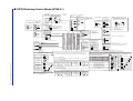
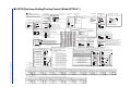
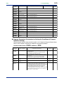
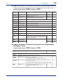
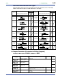
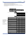
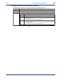
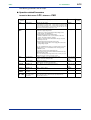
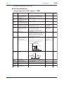
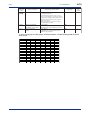
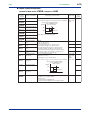
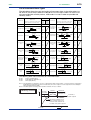
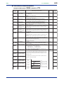
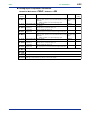
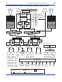
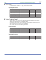
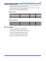
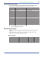
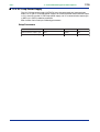
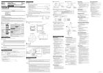
Loop2 heating-side control output Current/voltage Relay contact output pulse output IMPORTANT Change the setting of the control output type (OT1 and OT2) parameters to the Heating/Cooling Control. 0-20mADC, 4-20mADC Voltage pulse (12 V) Loop2 PV input * Factory-set to “TC type-K.” See “2. Initial Settings.” TC input 48 49 COM 50 RS-485 communication - 47 24 Contact rating: 250 V AC, 3 A 30 V DC, 3 A (resistance load) 42 + 0-20mADC, 4-20mADC 42 b 43 43 B 29 SDA(-) + 46 - 47 Default: 4-20 mA DC * Retransmission output 2 is available only when “relay” is selected as the Loop2 heating-side control output. NO COM Power supply N 3 Contact rating: 250 V AC, 3 A 30 V DC, 3 A (resistance load) Power supply L 2 CAUTION 8 Before carrying out wiring, turn off the power to the controller and check that cables to be connected are not alive with a tester or the like because there is a possibility of electric shock. 9 10 Allowable range: 100-240 V AC (10%) (free voltage) 50/60 Hz shared 30 26 RDA(-) 27 SG SG 12 + 13 - 1 41 31 21 11 21 + 42 32 22 12 22 - 3 43 33 23 13 4 44 34 24 14 5 45 35 25 15 6 46 36 26 16 7 47 37 27 17 8 48 38 28 18 9 49 39 29 19 50 40 Note: Connecting a 250 Ω resistor to the terminals is optional. Model: X010-250-2 (resistor with M3.5 crimp-on terminal lugs) mV/V input 2 10 250 Ω 4-20mA 13 - 13 B * Wiring can only be carried out for controllers with auxiliary analog input. Auxiliary analog input * Select this option from the OT1 parameter. 1 12 + 12 + 13 - Relay contact output NC RTD input 11 A RSA(-) Loop1 heating-side control output 43 - * When receiving 4-20 mA DC current signals, set the PV input type to 1-5 V DC (setpoint “41”). 12 b mV/V input 42 + TC input with communication functions. 28 RSB(+) 25 RDB(+) Default: Unspecified retransmission type 41 A * Wiring can only be High performance RS-485 communication carried out for controllers 23 SDB(+) 䊏 Receiving 4-20 mA DC Current Signals with the Controller Loop1 PV input * Not configured at factory before shipment. See “2. Initial Settings.” Communication 1 Communication 2 (PSL1) (PSL2) + 46 Retransmission output 2* RTD input NC NO * Select this option from the OT2 parameter. <Toc> ■ UP750 Dual-loop Heating/Cooling Control (Model UP750-5䊐) 30 Specify in a range of 1-5 V DC, 0-2 V DC, or 0-10 V DC. * Factory-set to “PV retransmission.” Retransmission output 1* 15 V DC loop power supply* Default: 1-5 V DC 14 + * Select this option from the OT1 parameter. * Retransmission output 2 is available only when “relay” is selected as the Loop1 heating-side control output. Loop1 heating-side control output Current/voltage pulse output Retransmission output 2 17 - 20 17 - 15 - 0-20mADC, 4-20mADC 14.5-18.0 V DC (21 mA DC max.) Default: 4-20 mA DC 14 + 16 + 0-20mADC, 4-20mADC Voltage pulse (12 V) 14 + 4-20 or 0-20 mA DC Loop1 cooling-side control output Default: Unspecified retransmission type 16 + 15 - 15 - * Retransmission output 1 is not available if a 15 V DC loop power supply is used. * If you define the Loop1 cooling-side contorl output as continuous output,retransmission output 1 and the 15 V DC loop power supply can no longer be used. 4-20 or 0-20 mA DC Default: 4-20 mA DC Note: Select this option from the OT1 parameter. Default: 4-20 mA DC External contact outputs PV event 1 output DO1 6 Relay PV event 2 output DO2 5 Instrument alarm 1 output DO3 4 Common COM 7 Time event 1 output DO4 34 Time event 2 output DO5 33 Time event 3 output DO6 32 Time event 4 output DO7 31 Common COM 35 External contact inputs Switch between the ON and OFF states of the DI1 to DI4 contact inputs to select from program pattern numbers 1 to 15. (Select a number during a RESET state.) Note 1: If you define the DO2 as the cooling-side control output, the DO5 serves as the Loop2 alarm 1 output. Inversely, if you define the DO5 as the Loop2 cooling-side control output, the DO2 serves as the Loop1 alarm 2 output. Note 2: If you define the DO3 as the Loop1 cooling-side control output, the DO4 serves as the Loop1 alarm 4 output. Inversely, if you define the DO4 as the Loop1 cooling-side control output, the DO3 serves as the Loop1 alarm 3 output. If the Loop1 cooling-side control output is the current, the DO3 serves as the Loop1 alarm 3 output, and the DO4 serves as the Loop1 alarm 4 output. 1 2 3 4 5 6 7 8 9 UP DI1 19 Contact 10 11 12 13 14 15 +5V DI2 DI1 ON OFF ON OFF ON OFF ON OFF ON OFF ON OFF ON OFF ON DI2 OFF ON ON OFF OFF ON ON OFF OFF ON ON OFF OFF ON ON DI2 18 DI3 OFF OFF OFF ON ON ON ON OFF OFF OFF OFF ON ON ON ON DI3 40 +5V DI4 39 +5V DI4 OFF OFF OFF OFF OFF OFF OFF ON ON ON ON ON ON ON ON * Loop1: Select from the OT1 parameter. Loop2: Select from the OT2 parameter. +5V DI3 DI4 Start of program operation when DI5 changes from OFF to ON DI5 38 +5V +5V Stop of program operation when DI6 changes from OFF to ON DI6 37 Start of local-mode operation when DI7 changes from OFF to ON DI7 36 Common COM 20 Transistor contact DI1 +5V DI5 DI6 DI7 19 18 40 39 38 37 36 COM 20 Contact rating: 12 V DC, 10 mA or more * OT1 is a setup parameter. You can change the settings of the parameter OT1 to change the Loop1 control output types. See “2. Initial Settings.” Correspondence between parameter OT1 and heating-side output types/cooling-side output types of Loop1 OT1=5 OT1=6 OT1=7 OT1=8 OT1=9 OT1=10 OT1=11 OT1=12 Heating side: Relay output (terminals 1 , 2 and 3 ) Cooling side: Relay output (terminals 4 and 7 ) Heating side: Voltage pulse output (terminals 16 and 17 ) Cooling side: Relay output (terminals 4 and 7 ) Heating side: Current output (terminals 16 and 17 ) Cooling side: Relay output (terminals 4 and 7 ) Heating side: Relay output (terminals 1 , 2 and 3 ) Cooling side: Transistor output (terminals 34 and 35 ) Heating side: Voltage pulse output (terminals 16 and 17 ) Cooling side: Transistor output (terminals 34 and 35 ) Heating side: Current output (terminals 16 and 17 ) Cooling side: Transistor output (terminals 34 and 35 ) Heating side: Relay output (terminals 1 , 2 and 3 ) Cooling side: Current output (terminals 14 and 15 ) Heating side: Voltage pulse output (terminals 16 and 17 ) Cooling side: Current output (terminals 14 and 15 ) Heating side: Current output (terminals 16 and 17 ) Cooling side: Current output (terminals 14 and 15 ) * OT2 is a setup parameter. You can change the settings of the parameter OT2 to change the Loop2 control output types. See “2. Initial Settings.” Correspondence between parameter OT2 and heating-side output types/cooling-side output types of Loop2 OT2=4 OT2=5 OT2=6 OT2=7 OT2=8 OT2=9 Heating side: Relay output (terminals 1 , 2 and 3 ) Cooling side: Relay output (terminals 5 and 7 ) Heating side: Voltage pulse output (terminals 16 and 17 ) Cooling side: Relay output (terminals 5 and 7 ) Heating side: Current output (terminals 16 and 17 ) Cooling side: Relay output (terminals 5 and 7 ) Heating side: Relay output (terminals 1 , 2 and 3 ) Cooling side: Transistor output (terminals 33 and 35 ) Heating side: Voltage pulse output (terminals 16 and 17 ) Cooling side: Transistor output (terminals 33 and 35 ) Heating side: Current output (terminals 16 and 17 ) Cooling side: Transistor output (terminals 34 and 35 ) 1-15 3rd Edition: May 31, 2006-00 OT1=4 <1. Installation> Transistor IM 05E01B02-51E Relay contact rating: 240 V AC, 1 A 30 V DC, 1 A (resistance load) Transistor contact rating: 24 V DC, 50 mA UP * The functions of the external contact inputs are the defaults for dual-loop heating/cooling control. To change the functions, reconfigure the contact input registration setup parameters. * The functions of the external contact outputs are the defaults for dual-loop heating/cooling control. To change the functions, reconfigure the contact output registration setup parameters.