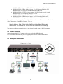
1
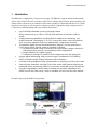
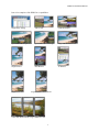
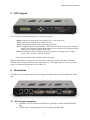
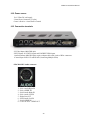
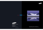
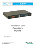
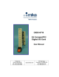
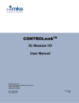
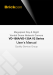
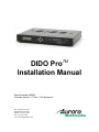
TM
DIDO Pro
Installation Manual
Manual Number 060925
Firmware Version 1.11 Rev: 3122 and above
205 Commercial Court
Morganville, NJ 07751
Phone: (732) 591-5800
Fax: (732) 591-5801
www.auroramultimedia.com
DIDO Pro Installation Manual
TABLE OF CONTENT
1
INTRODUCTION .................................................................................................................................2
2
ACCESSORIES .....................................................................................................................................4
2.1
OPTIONAL ACCESSORIES ..................................................................................................................5
3
IR REMOTE AND BASIC KEY FUNCTIONS .................................................................................7
4
QUICK START GUIDE .......................................................................................................................8
5
LCD / KEYPAD.....................................................................................................................................9
6
CONNECTIONS ...................................................................................................................................9
6.1
6.2
6.3
7
A/V & CONTROL CONNECTORS ........................................................................................................9
POWER CONNECTOR .......................................................................................................................10
EXAMPLES CONNECTIONS ..............................................................................................................10
OPERATING THE DIDO PRO.........................................................................................................12
7.1
REMOTE CONTROL FUNCTIONS ......................................................................................................12
7.2
MENU STRUCTURE .........................................................................................................................13
7.2.1
MAIN MENU ...............................................................................................................................14
7.2.2
WINDOW SETUP .........................................................................................................................14
7.2.3
INPUT SETUP ..............................................................................................................................16
7.2.4
LAYOUT SETUP...........................................................................................................................17
7.2.5
OUTPUT SETUP ...........................................................................................................................19
7.2.6
SOUND SETUP .............................................................................................................................19
7.2.7
PRESET SETUP ............................................................................................................................20
7.2.8
SYSTEM SETTINGS ......................................................................................................................20
7.2.9
SIGNAL TIMING ..........................................................................................................................23
7.2.10 TIMER AND SCHEDULER .............................................................................................................23
8
VIDEO WALL FUNCTIONALITY ..................................................................................................26
9
REAL TIME IMAGE ROTATION...................................................................................................28
10
CONTROL SOFTWARE ...............................................................................................................29
11
FIRMWARE UPDATE...................................................................................................................31
12
CLONING ........................................................................................................................................32
13
RS-232 PROTOCOL.......................................................................................................................33
14
SPECIFICATIONS .........................................................................................................................39
14.1
14.2
14.3
14.4
14.5
SUPPORTED VIDEO TIMING ............................................................................................................39
POWER SOURCE ..............................................................................................................................40
CONNECTION TERMINALS ...............................................................................................................40
DIMENSIONS ...................................................................................................................................42
WEIGHT ..........................................................................................................................................42
15
LIMITED LIFETIME WARRANTY............................................................................................43
16
FCC PART 15 STATEMENT ........................................................................................................44
17
INDEX ..............................................................................................................................................45
I
DIDO Pro Installation Manual
1 Introduction
The DIDO Pro is a high quality video processor engine. The DIDO Pro supports advanced functionality
such as video format /scan rate conversions, audio effects, real time image rotation (patents pending), and
window effects. All these can be controlled via IR remote and RS-232 commands and the device is small
enough to fit in tight areas. The progressive output(s) produces a high quality image using the latest 3:2 /
2:2 pull-down, motion handling, and noise reduction technologies.
•
Up to 165MHz bandwidth on the inputs and outputs.
Allows resolutions up to 1900 x 1200 @ 60Hz and can de-interlace 1080i to
1080p
•
Image enhancing capabilities including Motion Adaptive De-interlacing, Lowangle Directional Interpolation, 3:2 & 2:2 inverse pull-down, Moiré cancellation,
color correction, adaptive flesh tone adjustments, image zoom & shrink.
•
The powerful AARE (Aurora Advanced Rotation Engine) / Picture-and-Picture
(PAP) engine offers several modes of operation including:
1. Hi-resolution Quad Image or Side-by-Side (split screen) images. Perfect for
teleconferencing, security, command and control applications.
2. Image Rotation (for digital signage)
3. Translucent Overlays to maximize main image size while still seeing PiP
•
Accepts digital and analog video inputs through a combination DVI/ RGBHV/
YPbPr connectors and S-Video/Composite input connectors
•
Includes audio propagation delay compensation to properly sync with input video
•
Internal Event Scheduler with Real Time Clock allows AARE special effects to be
scheduled locally and among DIDO Pro units when connected via the RS-485 bus
•
Firmware upgradeable. New firmware releases can be easily uploaded to the
DIDO Pro with the Flash utility, which is available for free from Aurora's website.
Example Setup using the DIDO Pro quad mode:
2
DIDO Pro Installation Manual
Just a few examples of the DIDO Pro’s capabilities:
Single Image Scaling
Side by Side
Quad Mode Equal
Quad Mode 1 & 3 Top/Bottom
Quad Mode 1 & 3 Left/Right
Single with Translucent PiP
Single Rotated
Dual Rotated
Tri Rotated
Single Rotated PiP
Single Rotated Translucent PiP
\
Video Wall Mode Rotated Using 3 DIDO Pro Units
3
DIDO Pro Installation Manual
2 Accessories
Supplied accessories:
1 - 12V / 14.4W DC wall power supply or International Supply Kit if applicable
1 - 8 pin mini DIN to 8 RCA Female audio I/O cable
2 - S-Video to Composite Video Adaptors
1 - RS-232 Adaptor Cable (6 Pin Mini-Din to 9 Pin D-Sub)
1 - IR Remote
All supplied components are shown on the picture below:
12V / 14.4W Supply
Audio Breakout Cable
International Supply with Adaptors
S-Video to Video Adaptors
4
RS-232 Control Cable
IR Remote
DIDO Pro Installation Manual
2.1
Optional Accessories
Optional accessories available from Aurora Multimedia:
SRK-001 Single Rack Mount Kit
DRK-001 Dual Rack Mount Kit
CA0020-1 DVI-I to DVI-D / VGA Adapter Cable
CA0022-1 DVI-I to DVI-D / RCA Adapter Cable
CA0021-1 DVI-I to DVI-D / BNC Adapter Cable
DIDO Pro LOOP KIT RS-485 Loop Through Kit for
connecting multiple DIDO Pro units
5
DIDO Pro Installation Manual
CA0017-6 200MHz 6ft DVI-I to DVI-D / VGA(15pin D SUB) Breakout Cable
CA0016-6 165MHz 6ft DVI-I to DVI-D / 5 BNC Breakout Cable
6
DIDO Pro Installation Manual
3 IR Remote and basic key functions
The DIDO Pro can be controlled using an IR remote control, or via the front panel, or RS-232 commands.
The remote is addressable for installing with multiple DIDO Pro units. To change the address on the
remote:
- Press and hold the ‘Up’ and ‘Down’ arrows together for 5 seconds. The red LED will start to
blink
- Enter the address (0-255) and press ‘Select’
In order for the IR remote to properly control a DIDO Pro, both devices (IR remote and the DIDO Pro)
have to have the same address. See System Setup Menu for more information on how to change the
DIDO Pro’s address.
7
DIDO Pro Installation Manual
For details of DIDO Pro operation, refer to the corresponding chapter of this document.
Below is a brief description of the remote transmitter and the keys used for DIDO Pro control.
IR Remote
POWER
ZOOM
CROP
POS
SIZE
VOLUME +
VOLUME MUTE
ARROWS
MENU
SEL
EXIT
0..9, DIGITS
INFO
ROTATE
DVI A
RGB A
VIDEO A
DVI B
RGB B
VIDEO B
SINGLE
DUAL
TRI
QUAD
SWAP
FREEZE
PRESET KEYS
Function
Toggles Power On and Standby
Brings up Zoom selection for each window 0-100%
Brings up Crop selection for each window 0-100%
Brings up Position selection for each window 0-100%
Brings up Size selection for each window 0-100%
Increases Volume level
Decreases Volume level
Toggles the volume Mute On/Off
Moves the cursor up/down/left/right when Menu is active
Displays Main Menu
Selects option in Menu
Finishes input in dialog panels
Exits 1 menu level
Not in use
Displays current input/output timings and FW version
Rotates output image by 0, 90, 180, 270 degrees
Selects DVI Side A Input
Selects RGB/YPbPr Side A Input
Selects Video/S-Video Side A Input
Selects DVI Side B Input
Selects RGB/YPbPr Side B Input
Selects Video/S-Video Side B Input
Selects 1 window on the output
Selects 2 windows on the output
Selects 3 windows on the output
Selects 4 windows on the output
Swaps the sources between the windows
Freezes the current window
P1 – P4 selects the stored preset
4 Quick Start Guide
1. Make sure the DIDO Pro unit and the Display are both disconnected from power.
2. Connect the DIDO Pro unit to the Display’s DVI, VGA, or YPbPr port as required.
3. Connect the appropriate video sources to input connectors of DIDO Pro (see “Connections”
chapter for details).
4. Connect audio input/output to the 8-pin mini-DIN connector of the DIDO Pro (see
“Connections” chapter for details).
5. Connect the power source to the Display (refer to Operating Instructions of the Display).
6. Connect the supplied 12v DC adapter to the DIDO Pro and the power outlet. The LCD will light
and after 5 seconds, the firmware rev will appear. About 15 seconds later, the DIDO Pro will
complete initialization and display the output resolution and format on the LCD. The last
settings of the DIDO Pro will take effect.
8
DIDO Pro Installation Manual
5 LCD / Keypad
The LCD helps to navigate through menus with the front keypad.
- Menu: brings up the menu on the screen and the LCD - exits menu levels.
- Select: brings up next menu level or confirms an entry.
- Arrows: navigates through the menus and changes selections.
- Power: Toggles the Power On and Standby. This button can also be used to restore all default
values if it’s held down for 10 seconds when the power connector is first applied. Factory
default for the output is RGBHV XGA 60Hz.
- Presets: Holding the select key and pressing the up arrow key will trigger preset 1, right is
preset 2, down is preset 3, and left is preset 4.
Note: Restoring default values will delete all saved settings.
When no OSD (Menu) is present, the ‘Up’ and ‘Down’ arrow keys will show the status of different
functions such as output resolution, layout, input source, etc. The ‘Right’ and ‘Left’ arrow keys can be
used to scroll the text that can not be seen on the LCD.
6 Connections
The DIDO Pro has 6 independent inputs and 2 outputs. In addition, there are audio and RS-232 control
ports.
6.1
A/V & Control connectors
•
•
CONTROL: RS-232 connection and RS-485 loop through to control multiple DIDO Pro
units.
AUDIO: for use with supplied audio breakout cable (8pin Mini DIN).
9
DIDO Pro Installation Manual
•
•
•
•
•
S-VIDEO SIDE A (4-pin mini DIN): S-Video or Composite (supplied adaptor) input.
DVI/RGB/YPbPr SIDE A: for hi-res inputs. If a DVI-I breakout cable is used,
RGBHV/YPbPr can be input as an additional source to the DVI.
DVI/RGB/YPbPr OUTPUT for hi-res outputs. If a DVI-I breakout cable is used
RGBHV/YPbPr can be output in addition to the DVI.
S-VIDEO SIDE B (4-pin mini DIN): S-Video or Composite (supplied adaptor) input.
DVI/RGB/YPbPr SIDE B for hi-res inputs. If a DVI-I breakout cable is used,
RGBHV/YPbPr can be inputted as an additional source to the DVI.
The supplied audio input/output adapter cable has labels on cables near RCA connectors. These labels
indicate the purpose of each RCA connector. They are:
Side A Left Audio, Side A Right Audio, Side B Left Audio, Side B Right Audio,
Side A SPDIF IN, Side B SPDIF In, Line Out Left / SPDIF Out, Line Out Right
The respective audio input channels (A or B) are selected from the menu or RS-232 command.
6.2
Power connector
Connect the supplied 12V DC adapter to the power jack of the DIDO Pro unit.
It is recommended to connect the power supply only after all other connections are done.
6.3
Examples Connections
10
DIDO Pro Installation Manual
11
DIDO Pro Installation Manual
7 Operating the DIDO Pro
The DIDO Pro has many advanced features to enhance the typical viewing experience. A user can switch
the unit on or off, control volume level, switch the current source, rotate an image, and many other
functions.
Advanced functionalities may differ in some of the operating modes, which will be described in more
details and in the subsequent chapters of this document.
7.1
Remote Control Functions
Key: Vol+/Increases or decreases the volume level.
Keys: 0-9
Not in use.
Key: Menu
Displays the Main Menu (see the Menu System chapter).
Key: Sel
Enters selections / confirms changes in the menu.
Key: Exit
Exits one level in the menu or turns off OSD that’s being displayed.
Key: Power
Toggles the power on or standby.
Key: Rotate
Rotates output image by 0, 90, 180, and 270 degrees.
Key: Swap
Swaps input sources between window 1 and window 2 when the DIDO Pro is in PiP or SBS mode.
Keys: Info
Displays current sources, input / output timing information, and FW version via OSD. This information
will be displayed for 5 seconds.
Key: Freeze
When pressed, it stills the current image on the screen. Pressing again will resume motion.
Keys: Zoom, Crop, Pos, Size
When pressed, it will bring up a menu to select the window to be adjusted. All these selections have a
range of 0-100 percent with tenths of a percent accuracy for a total of 1000 points of precision adjusting.
•
•
•
Zoom: enlarges or shrinks the output image.
Crop: is specific to an input and is used when under scanning an image to remove unwanted
areas around the border. It helps balance the inputs with each other.
Size: is used to separately adjust of the horizontal and vertical size of an output image.
12
DIDO Pro Installation Manual
•
Position: moves the window up/down or left/right. Position will only work if the image is
zoomed.
Keys: Single, Dual, Tri, Quad
These keys select picture layout (how many windows will be displayed) of the output.
• Single: only one picture is displayed on the output.
• Dual: toggles between PiP and SBS. When in PiP mode, translucency can be adjusted using
Up/Down arrows (no menus are present).
• Tri: three images are displayed on the output
• Quad: four images are displayed on the output and will toggle between the 2 type of quad
modes.
There are limitations when using these features:
• There is a 7 seconds delay when changing between quad mode and rotated images.
• Quad mode can not be rotated. Only Single, PiP, Dual and Tri modes can be rotated.
• In Tri mode, window 1 can only take Side A inputs. Windows 2 and 3 can only take
Side B inputs.
• In Quad mode, window 1 and 2 (top) can only take Side A inputs. Windows 3 and 4 (bottom)
can only take Side B inputs.
Keys: Side A/B DVI, RGB, VIDEO
These six keys will select the source to be displayed on the screen. In Single mode, the keys select the
source immediately. In PiP, Dual, Tri, or Quad mode, a dialog will appear asking for window selection.
Keys: P1-P4
Preset keys which make the usability of the DIDO Pro much easier. When a preset is recalled, it will
restore the saved screen conditions set at the time of initially saving the preset. Up to 99 presets can be
saved and recalled via the menu or RS-232. Only the first 4 can be recalled with the quick keys on the
remote. Presets are very useful for effects, image resizing, and especially video wall functions. Presets 14 can also be recalled via the front keypad.
7.2
Menu Structure
The menu system allows a user to control various aspects of DIDO Pro configurations.
For all menus, Up/Down arrows move the cursor (yellow highlighted selection) up/down. Central key
(SEL key) selects the current submenu/option, confirms changes, and finishes text entry (passwords,
presets, etc.). Left/Right arrows change the currently active option, if possible.
The sub-menus will be discussed in more details in the subsequent chapters.
13
DIDO Pro Installation Manual
7.2.1 Main Menu
Main Menu contains the branches to all sub-menus. All different features can be accessed from this Main
Menu.
7.2.2 Window Setup
This is where source, size, position, zoom, and crop can be modified per window. Once selected, the
choice of window for modification will appear. Window Setup affects the characteristics of the window
itself and not the image inside the window.
Source allows a user to assign input(s) to available window(s). For example, the menu below shows what
source is assigned to each available window(s). If Quad mode is selected, then four windows would be
available to select from.
14
DIDO Pro Installation Manual
Window Size gives the ability to change the horizontal and vertical sizes of a window.
Window Position gives the ability to change the horizontal and vertical positions of a window. Note that
to move a window, the size of that window must be smaller than the active area.
Window Zoom gives the ability to change both the horizontal and vertical sizes of a window at the same
time to keep the image proportional.
Window Crop allows each of the edges of an image to be adjusted into the window to help reduce noise
specific to an input. Crop is specific to the current resolution of the input inside the window. It must be
saved into a profile in order for it to be automatically applied. If a new resolution is applied, crop must be
re-adjusted. Crop is best for video images that have noisy borders. If the arrow key is pressed once, the
value will change by one pixel. If an arrow is pressed and held for 2 or more seconds, the value will
change by 10 pixels instead.
Note: For Window Size, Window Position, and Window Zoom, there are 1000 points of accuracy. If the
arrow key is pressed once the value will change by tenths of a percent. If an arrow is pressed and held
for two or more seconds, the value will change by 1 percent instead of tenths.
15
DIDO Pro Installation Manual
Video wall setup allows quick setup of a multiple monitor system. Enter the total number of columns and
rows as well as the row and column of the DIDO Pro unit being setup followed by apply changes. The
output will be changed to the appropriate size. It is still necessary to account for the bezel size of the
display device by manually changing the zoom, size or crop. When done, make certain to save in a
preset.
7.2.3 Input Setup
Input Setup allows a user to manually configure different connector inputs.
SVID (A/B):
manual selection.
Auto, S-Video, and Video. If the image can not lock well due to poor sync, use the
DVI (A/B):
Auto, Norm PC, Wide PC, and Video. The manual selection helps to set correct
input timing such as Video or PC. This will help the DIDO Pro to better sync on an input.
RGB (A/B):
Auto, Norm PC, Wide PC, and Video. The manual selection helps to set correct
input timing such as Video or PC. This will help the DIDO Pro to better sync on an input.
RGB/YPbPr (A/B):
RGBHV, RGsB, and YPbPr. Select the type of signal connected to the RGB input.
16
DIDO Pro Installation Manual
ADC Settings currently has phase control as the selection. This is used is there is noise on the YPbPr
input due to the cable or other factors.
7.2.4 Layout Setup
The Layout Setup menu determines the way the windows are positioned and how many windows are
displayed.
Layout selects window layout from Single, PiP, Dual, Tri, and Quad
Stack Type selects the positions of windows 1 and 2 in Dual or Tri modes. The selections are Left-Right
and Up-Down.
Left-Right Dual Mode
Up-Down Dual Mode
17
DIDO Pro Installation Manual
Quad Type selects the type of quad mode. The 2 choices are 4 equal quadrants or 1 large (75%) 3 small
(25%). Using the stack type the windows can be repositioned.
Quad Mode Equal
Quad Mode 1 & 3 Top/Bottom
Quad Mode 1 & 3 Left/Right
Rotate will rotate picture by 0, 90, 180, and 270 degrees.
PiP Transparency sets the transparency level (16 levels) of the pip window when in PiP mode.
PiP Size adjusts the size of the PiP window from 0 - 100 percent with accuracy down to the tenths.
PiP Position adjusts the position of the PiP window from 0 - 100 percent with accuracy down to the
tenths.
18
DIDO Pro Installation Manual
Flip Setup changes the input image orientation with respect to the output. This allows for mirror images
or back to back images in rotated modes to create new effects.
Horizontal Disabled
Horizontal Enabled
7.2.5 Output Setup
Output timing for the DVI/RGBHV/YPbPr connector is selected here. Output type can also be modified
from this menu for the analog portion of the connector. The selections are RGBHV, RGsB, YPbPr, and
No Output.
Video settings adjust the brightness, contrast, saturation, and hue of picture output. All windows will be
affected when adjusted.
7.2.6 Sound Setup
Volume
Input
Mute
Delay
-- Selects the current (default) volume level
-- Selects Side A or B audio input
-- Turns on and off the audio output
-- Enter the amount of audio delay to be added to compensate not just for DIDO
Pro video processing but other equipment as well.
19
DIDO Pro Installation Manual
7.2.7 Preset Setup
This menu allows the saving and loading of up to 99 presets. To save or load a preset, select Load Preset
or Save Preset. Then change or enter preset number to be saved or loaded. Press “SEL” to confirm
changes. If it is saving, the OSD will display “Preset is being saved”. Presets can take up to 2 seconds to
load. So if only simple switching sources is needed, use the keys or RS-232 commands for quicker
changing of inputs. Presets are great for a starting point when many things need to change at once as it
stores everything like output resolution, modes, input setup, audio settings, video settings etc.
7.2.8 System Settings
This menu allows the selection of items which affect the overall DIDO Pro operation.
Unit Address allows many DIDO Pro JR units to be connected via RS-485. When connecting multiple
DIDO Pro JR units via the RS-485, each unit must be addressed differently. This address will be used
when controlling via RS-232 from a control system or PC. In addition, the last unit in the chain must
have
20
DIDO Pro Installation Manual
RS-485 Termination enable.
The IR remote is also addressable (see IR remote section) and if set to the same address as the DIDO Pro
Jr., it will control only that DIDO Pro Jr. This feature is very useful when multiple DIDO Pro Jr. units are
present to prevent inadvertently controlling other units.
Remote Query is a diagnostic tool used to check for any DIDO Pro remote’s current address even if it is
not matched to the address of that DIDO Pro unit.
OSD Setup turns on/off the Menu Transparency and OSD.
Menu Transparency allows the menu to blend with the background.
Show OSD can disable the On Screen Display. When using the front keypad for setup via the LCD, it will
prevent the OSD from coming on the screen. This is handy when making changes to the system while it is
being viewed.
Background Color determines the color of the window when no input signal is present.
Noise reduction allows the DIDO Pro to clean up an image with random noise caused by poor or weak
signal. There are two types of noise reduction filters available. The first one is Spatial filter which is good
for signals from poor TV reception. The second one is Temporal filter which is a good overall noise
reduction to clean up an image. There is a penalty when using noise reduction which is the softening of
the image. Best way to use noise reduction is trial and error to see what works best for the application.
Motion handling is for DIDO Pro’s motion adaptive de-interlacing. There are three options to choose
from. Option 2 gives the best overall compromise of feathering and jitter when enabling this feature.
Once again, it is best that different options are used with the content to see which works best.
21
DIDO Pro Installation Manual
Scaling Filter is for the graphics channel. This should be enabled in most cases especial when an image
is being down scaled or reduced in sized. The scaling filter is not used when an image is up scaled or
increased in size.
ADC Calibration is for the RGBHV amd YPbPr inputs color settings. The Auto will automatically adjust
the gain and offset for each color when a test pattern is inputted. The Manual allows adjustment to a
user’s reference or with external color analyzer.
DIDO Pro Reconfig will re-sync all the current input signals as if the inputs were disconnected and
reconnected.
Default Settings will reset the DIDO Pro to factory settings (default settings). All customized settings will
be deleted.
22
DIDO Pro Installation Manual
7.2.9 Signal Timing
This menu allows the adjusting and adding of input and output resolutions. There are currently two user
profiles for customized input and output resolutions. Horizontal Frequency and Pixel clock are
automatically calculated inside the DIDO Pro. When done making changes, select Apply Changes to
save. Keep in mind any change made affect all inputs using the resolution as well as outputs.
WARNING: When making custom resolutions, make sure the device that accepts the signal is capable of
handling it. Failure to do so may result in damage in some devices. Consult the User Manual before
applying new resolutions with different frequencies.
7.2.10 Timer and Scheduler
The timer scheduler is great for display signage. The DIDO Pro has a built in real time clock which has
backed-up battery. This menu allows for the time and date to be set as well as two types of scheduling.
Current Date and Time is important to the operation as the accuracy of the scheduler is based upon the
settings in this menu. If the region the DIDO Pro is located in has daylight savings then it should be
turned on to keep the time correct throughout the year.
23
DIDO Pro Installation Manual
Time Events are events based on the time of day. The DIDO Pro can have 5 different time events
programmed.
When the an event is turned on, the time selected will cause the DIDO Pro and all other DIDO Pro units
connected on the RS-485 bus to carry out a preset, power on, or power off.
Timer Events are events based on a cycling time line. This means the DIDO Pro will carry out repeating
functions in a timeline. The DIDO Pro can have 5 different timer events programmed. When setting up
the timer events, the last event type must be set to END. If not, timer events will be executed once.
Because of this, there are actually four usable events.
When an event is turned on, the timer selected will cause the DIDO Pro and all other DIDO Pro units
connected on the RS-485 bus to carry out a preset, power on, or power off.
24
DIDO Pro Installation Manual
If multiple DIDO Pro units are used, the schedulers can be used in all units to gain more events. It is not
necessary to program all DIDO Pro units with the same events as they will conflict (time conflict) with
each other. However, if they are programmed at different times, it will work properly with no conflict.
25
DIDO Pro Installation Manual
8 Video Wall Functionality
When multiple DIDO Pro units are used, a very powerful but yet cost effective video wall can be created.
The DIDO Pro can create video walls that have real time vertical rotation of single or multiple images.
For easy setup, the DIDO Pro has a Video Wall Setup menu under Windows Setup. This menu allows a
user to enter the amount of rows and columns of the video wall as well as the current location of the
DIDO Pro. Once entered, the DIDO Pro will calculate the proper size for the unit which can then be
saved into a preset.
Example of 2x2 Video Wall Settings:
For this example, 4 DIDO Pro units will be needed. The output of each DIDO Pro will be connected to a
display that’s assigned to that specific DIDO Pro. The source to be shown across the four displays will
need to be put through a distribution amplifier (D/A) to feed the same source into the four DIDO Pro
units. From Video Wall Setup of each DIDO Pro:
- Set number of columns and rows to 2 (2x2).
- Set column and row of each DIDO Pro to its corresponding quadrant. In 2x2 mode, if column
and row are set to 1, then this DIDO Pro will display the 1st quadrant. If column is set to 2
and row is set to 1, then this DIDO Pro will display the 2nd quadrant and so on.
Note on video wall setup:
- Input the highest possible resolution because it will produce a better picture on the output (the
output picture will not be zoomed as much).
- Avoid using composite video sources as the dot crawl will be magnified. S-Video, YPbPr,
RGBHV, and DVI are the better choices with DVI providing the cleanest picture.
- Use the DVI output of the DIDO Pro units because it will keep the image clean and sharp.
- Match the output resolution of the DIDO Pro to the displays native resolution.
Wire the RS-232/485 as per the connection diagram located in the back of the manual and set the address
in each DIDO Pro unit so they are different from each other. This will help when using presets, IR remote
control, and RS-232 control. The DIDO Pro LOOP KIT can be purchased separately for easy
connections.
Ideally a video generator should be present with a grid pattern to set each DIDO Pro unit to the
appropriate quadrant. When using the grid make certain all the boxes are square even though the screens
may be rectangular. Also, make certain the display device has all zoom modes and aspect controls set to
default positions. Using the Zoom, Size, Position, and Crop to adjust and center the picture and store it in
a preset. Even though each DIDO Pro unit will be zoomed to a different area of the original image, it is
best to store it to the same preset as all the other units. When that preset is recalled, all units will go to the
appropriate area they were set for. Repeat this for each source and each effect desired.
26
DIDO Pro Installation Manual
Depending on input and output resolutions, video walls up to 32 x 32 can be created. Video walls with
rotated images can be created as well with a combination of both rotated and non-rotated to create a
puzzle effect.
27
DIDO Pro Installation Manual
9 Real Time Image Rotation
The DIDO Pro can do real-time image rotation with resolutions up to 1900 x 1200 @ 60Hz. Its patent
pending multi-image rotation allows a display to show multiple rotated images at the same time.
These examples below show some of the many possibilities.
Single Rotated
Dual Rotated
Tri Rotated Single
Rotated PiP
Single Rotated Translucent PiP
Images can be cropped and zoomed for stretch to fit. The edges can also be cut off to show only the
middle for runway effects and thus keeping the image proportional.
Rotated flat displays have many benefits as listed below:
1) Two images can be displayed one on top of another to create two nearly 4:3 images.
2) Three images can be displayed one on top of the other to create three nearly 16:9 images.
3) In a presentation with images are rotated vertically, the presenter will not block any image on the
screen. With a horizontal display doing side by side images, it’s most likely that the image closer
to the presenter will be blocked.
4) Vertically rotated pictures can help preventing burn-in image on plasma display. With horizontal
display doing side by side, the top and bottom usually have black areas to keep the image
proportional. These black areas, if stay on for a long time, will cause the phosphor to burn
unequally.
As there are benefits to having rotated displays, a user may also want to still be able to show a display
horizontally. There are companies that make rotating wall mounts that can be operated manually or
motorized.
Display Devices manufactures motorized wall mounts for plasma and LCD displays. Check out
www.displaydevices.com for more info.
28
DIDO Pro Installation Manual
10 Control Software
Aurora Multimedia has developed control software for use with the DIDO Pro to make control of the unit
even easier. This firmware is available free of charge on the Aurora website www.auroramultimedia.com
It can be found in the DIDO Pro section under products.
The software is written in Flash as an executable file to be run from a PC’s communication port and can
also be run from Aurora WACI control systems.
The latest features and instructions of use can be found using the Help button at the top of the page. The
About button will reveal the Control Software’s revision number. Always make certain the DIDO Pro is
running the latest firmware to take advantage of new features.
29
DIDO Pro Installation Manual
Troubleshooting
Symptom
Key on remote is pressed but
nothing happens
The display does not turn on or
show an image
No control via RS-232
connection to DIDO Pro
DVI output has horizontal noise
going across intermittently
Video is black and white
S-Video does not lock
DVI has output but RGB does
not
No image on either output
Image is green on the input
Image is green on the output
Checks
Check to see if the batteries are good. If the batteries are
good – check the cable connections between the Plasma
Display and the DIDO Pro. Also, make certain the DIDO Pro
has power.
Check if the IR remote address is the same as the DIDO
Pro’s address in System Setup menu.
Check to see if the OSD from the DIDO Pro displays. If it
does check the source selection and/or cables for the
source. If there is no OSD then make certain the output
cable is connected properly and the output timing of the
DIDO Pro matches the capabilities of the display device.
Make sure the DIDO Pro is not in standby.
Check cable connection. If connection is ok, check baud
rate and address of DIDO Pro.
This could happen if a DVI cable is too long. Typical DVI
should not exceed 6ft. Some after market products can
enhance the length of DVI. Double check the specifications
before using these types of DVD cables.
Under Input Settings, check the selection for the SVID. If
the video sync is weak try using video selection instead of
Auto. Also, make certain it is not set for S-Video.
Under Input Settings check the selection for the SVID.
Make certain the selection is not set for Video.
If the content has HDCP, the RGB/YPbPr output will be
disabled due to copyright protection. If it is not HDCP
protected, heck the Output Setup to make certain RGB is
not disabled.
Check output resolution is compatible with display device
and the DIDO Pro is not in standby mode.
Make certain the DIDO Pro input for RGB/YPbPr is set up
correctly.
If the output of the DIDO Pro is setup incorrectly (RGBHV
vs YPbPr vs RGsB) it may result in a green image.
30
DIDO Pro Installation Manual
11 Firmware update
The internal software of DIDO Pro (the firmware) can be updated. This is necessary since new FW will
correct bugs from previous versions or add new functionalities. The serial port of the DIDO Pro must be
connected to the RS-232 (“COM”) port of a PC-compatible personal computer, running MS-Windows 98,
2000, or XP operating systems. Make certain the DIDO Pro unit is set to 115k baud before updating
firmware. Always check the serial number on the DIDO Pro unit to make sure the new firmware is
compatible with the hardware revision. Some features may not work depending on DIDO Pro model,
which is determined by the four digit batch number (example: bbbb-SNxxxx with “bbbb” representing the
batch number).
Update procedure
• Create a directory for the DIDO Pro (such as C:\DIDO Pro).
• Save the attached files to the created directory.
• Unzip the files if necessary.
• Open a Win32 (Command Prompt) window (Start Æ Run Æ cmd Æ Enter).
• Change to DIDO Pro directory (C:\DIDO Pro).
• Type this command “DIDO Proldr.exe 1 DIDO Pro.did” and press “Enter.” (Note: To change the
COM port use the appropriate comm. port number in place of the 1)
• It will take approximately 20 seconds to finish programming and the device will restart itself. If
it does not restart, unplug the power and re-apply it after 5 seconds.
• Under System Settings select Default Settings and confirm.
Important: avoid programming the DIDO Pro using USB-RS232 adapter since it may not work
properly.
Example:
“DIDO Proldr.exe 1 DIDO Pro.did”
DIDO Proldr.exe: program loader
1: COM port used to program the DIDO Pro (for example, 2 is for COM 2)
DIDO Pro.did: firmware (this file name can be anything such as DIDO Pro040916.did)
Microsoft Windows XP [Version 5.1.2600]
(C) Copyright 1985-2001 Microsoft Corp.
C:\DIDO>DIDO ldr.exe 1 DIDOPro.did
DIDO Pro firmware loader V2.03 Copyright (c) 2003 Aurora Multimedia
Loading "DIDOPro.did"
Opening Com 1...
OK
Initiating bootblock.....
OK
Initiating load procedure...
OK
Transferring image header...
OK
Waiting for header response...
OK
Erasing flash...
OK
Loading flash image (137674 bytes)... 100% OK
Rebooting device...
Warning:
In the event the firmware update is interrupted during the transfer process, cycle the power on the DIDO
Pro and wait 30 sec after reapplying the power to start the transfer process again. The LCD screen may
be blank but that is normal if this should happen.
31
DIDO Pro Installation Manual
12 Cloning
The DIDO Pro can be cloned to save and restore all current parameters.
There are two steps involved in cloning procedure. They are:
1. Learning or downloading data (settings) from DIDO Pro to the computer.
2. Teaching or uploading data (settings) from computer to the DIDO Pro.
Before cloning the DIDO Pro, a folder which will be used to store data from the master DIDO
Pro needs to be created (for example: C\DIDO Pro\data). The clone utility (CloneLdr.exe) will be saved
to that directory.
Important:
DIDO Pro may not be cloned properly if a USB to RS 232 adapter is used.
Command lines for learning and teaching:
Learning:
Teaching:
CloneLdr.exe COM[Port#] /l File_Name.par
CloneLdr.exe COM[Port#] /s File_Name.par
CloneLdr.exe: clone utility.
COM[Port#]: serial port (such as 1 or 2) that is used for cloning.
/l: loading data from DIDO Pro to the computer.
/s: sending data from computer to the DIDO Pro.
File_Name.par: name of the file that will be used to store data from DIDO Pro.
32
DIDO Pro Installation Manual
13 RS-232 Protocol
Serial Control Setup:
115k 8N1 (Default)
Baud Rate:
1200 – 115k (Selectable).
Serial Connector Type: 9 to 6 pin RS 232 cable (NULL).
Note: this cable is supplied by the manufacturer.
The DIDO Pro is addressable. Units will be addressable from 000-254.
Address 255 or *** is reserved for broadcasting.
COMMAND FORMAT:
[Prefix][Address][Command][n][m] [<CR>]
?
!
~
ADDRESS
COMMAND
n, m:
<CR>
QUERY COMMAND (Does not have to be Case Sensitive)
COMMAND
(Does not have to be Case Sensitive)
RESPONSE
(ALL RESPONSES ARE CAPITALS)
000 – 254
(255 or *** is used for Broadcasting)
ASCII FORMAT
(See Command List)
variables
0D (hex) or 13 (decimal)
Note:
If a command doesn’t require variable(s), then nothing should be entered.
If a command does have variable(s), the response will include variable(s).
Example:
!001KEY_ZOOM<CR> Will tell unit addressed at 001 to carry out the Zoom command.
~001KEY_ZOOM<CR> Response from the DIDO Pro.
!***KEY_POWER<CR> Will tell all units to toggle the power.
!000HPOSIT <n> <CR> Set horizontal position at n.
~000HPOSIT <n> <CR> Response from DIDO Pro.
COMMAND LIST:
!
1
2
3
4
5
6
7
8
9
10
COMMANDS
KEY_P1
KEY_P2
KEY_P3
KEY_P4
KEY_NUM0
KEY_NUM1
KEY_NUM2
KEY_NUM3
KEY_NUM4
KEY_NUM5
FUNCTION
PRESET 1
PRESET 2
PRESET 3
PRESET 4
NUMBER 0
NUMBER 1
NUMBER 2
NUMBER 3
NUMBER 4
NUMBER 5
NOTE
Not used
Not used
Not used
Not used
Not used
Not used
33
DIDO Pro Installation Manual
!
11
12
13
14
15
16
17
18
19
20
21
22
23
24
25
26
27
28
29
30
31
32
33
34
35
36
37
38
39
40
41
COMMANDS
KEY_NUM6
KEY_NUM7
KEY_NUM8
KEY_NUM9
KEY_LEFT
KEY_RIGHT
KEY_UP
KEY_DOWN
KEY_SEL
KEY_MENU
KEY_EXIT
KEY_POWER
KEY_MUTE
KEY_INFO
KEY_ROTATE
KEY_ZOOM
KEY_CROP
KEY_POS
KEY_SIZE
KEY_A_DVI
KEY_A_RGB
KEY_A_VIDEO
KEY_B_DVI
KEY_B_RGB
KEY_B_VIDEO
KEY_SINGLE
KEY_DUAL
KEY_TRI
KEY_QUAD
KEY_FREEZE
KEY_SWAP
42
43
44
45
46
47
48
49
50
51
52
SETDEFAULT
PRESET n
S_PRESET n
RSADDR n
WINDOW n m
ROTATE n
LAYOUT m
OUTFORMAT n
HPOSIT n m
VPOSIT n m
HSIZE n m
FUNCTION
NUMBER 6
NUMBER 7
NUMBER 8
NUMBER 9
LEFT ARROW
RIGHT ARROW
UP ARROW
DOWN ARROW
SELECT
MENU
EXIT
POWER TOGGLE
AUDIO MUTE
INFORMATION
ROTATE
ZOOM
CROP
POSITION
SIZE
DVI SIDE A
RGB SIDE A
VIDEO/SVIDEO SIDE A
DVI SIDE B
RGB SIDE B
VIDEO/SVIDEO SIDE B
SINGLE MODE
DUAL MODE
TRI MODE
QUAD MODE
FREEZE
SWAP WINDOW
SOURCES
FACTORY DEFAULTS
RECALL PRESET
STORE PRESET
SET ADDRESS
SELECT WINDOW
ROTATE OUTPUT
SET LAYOUT
OUTPUT RESOLUTION
SET H. POSITION
SET V.POSITION
SET H.SIZE
34
NOTE
Not used
Not used
Not used
Not used
n = 00 to 99
n = 00 to 99
n = 000 to 254 (255 or ***: Broadcast)
n = 1, 2, 3, 4; m: input*
Degree of rotation: 90*(n); n = 0, 1, 2, 3
m = single, dual, pip, sbs, tri, and quad
n = output resolution**
n (window):1, 2, 3, 4; m = 0 to 1000
n (window):1, 2, 3, 4; m = 0 to 1000
n (window):1, 2, 3, 4; m = 0 to 1000
DIDO Pro Installation Manual
!
53
54
55
56
57
58
59
60
61
62
63
64
65
66
67
68
69
70
71
72
73
74
75
COMMANDS
VSIZE n m
SWAPIN
RECONFIG
HPOSITPIP n
VPOSITPIP n
HSIZEPIP n
VSIZEPIP n
RGBSYNC n m
SWAPWIN
POWERON
POWEROFF
MUTEON
MUTEOFF
VOLUME+
VOLUMEVOLUME n
AUDIOINPUT n
AUDIOOUTPUT n
AUDIODELAY n
OSDTRANS n
PIPTRANS n
ADCCALIBR
FREEZE n
76
77
78
79
80
81
82
83
84
85
86
87
88
89
90
91
92
93
94
BRIGHTNESS n
CONTRAST n
SATURATION n
HUE n
ZOOM n m
CROPLEFT n m
CROPRIGHT n m
CROPTOP n m
CROPBOTTOM n m
CROPSAVE n
CROPRESET n
OSDON
OSDOFF
VERFLIPON n
VERFLIPOFF n
HORFLIPON n
HORFLIPOFF n
STACK n
QUADTYPE n
FUNCTION
SET V.SIZE
SWAP INPUTS
RECONFIGURE DIDO Pro
SET H.POS FOR PIP
SET V.POS FOR PIP
SET H.SIZE FOR PIP
SET V.SIZE FOR PIP
RGB/YPbPr TYPE
SWAP INPUT
POWER ON
POWER OFF
AUDIO MUTE ON
AUDIO MUTE OFF
VOLUME UP
VOLUME DOWN
VOLUME LEVEL
AUDIO INPUT SOURCE
AUDIO OUTPUT TYPE
AUDIO DELAY
OSD TRANSLUCENCY
PIP TRANSLUCENCY
A/D RGB Auto Calibration
FREEZE OUTPUT
IMAGES
BRIGHTNESS CONTROL
CONTRAST CONTROL
SATURATION CONTROL
HUE CONTROL
ZOOM
CROP LEFT
CROP RIGHT
CROP TOP
CROP BOTTOM
CROP SAVE
CROP RESET
OSD ON
OSD OFF
VERTICAL FLIP ON
VERTICAL FLIP OFF
HORIZONTAL FLIP ON
HORIZONTAL FLIP ON
STACK DIRECTION
QUAD LAYOUT
35
NOTE
n (window):1, 2, 3, 4; m = 0 to 1000
Swap inputs from window 1 and 2
n = 0 to 1000
n = 0 to 1000
n = 0 to 1000
n = 0 to 1000
n = A, B; m = HV, SOG, YPRPB
Swap window 1 and 2 only (sbs, pip)
n: value is in percent (0% – 100%)
n: SOUND_A/B orSPDIF_A/B
n: Analog or SPDIF
n: value is in percent (0% – 100%)
n: value is in percent (0% – 100%)
n: value is in percent (0% – 100%)
n is 0 for off, 1 for on
n = 0 to 1000
n = 0 to 1000
n = 0 to 1000
n = 0 to 1000
n (window): 1,2,3,4 m = 0 to 1000
n (window):1, 2, 3, 4; m = pixels
n (window):1, 2, 3, 4; m = pixels
n (window):1, 2, 3, 4; m = pixels
n (window):1, 2, 3, 4; m = pixels
n (window):1, 2, 3, 4
n (window):1, 2, 3, 4
n: A or B (side A or side B)
n: A or B (side A or side B)
n: A or B (side A or side B)
n: A or B (side A or side B)
n = UD, LR
n: EQUAL, A, ,OR B
DIDO Pro Installation Manual
* Inputs: DVI_A, RGB_A, SVIDEO_A, DVI_B, RGB_B, SVIDEO_B.
** Output resolutions:
0
1
2
3
4
5
6
7
8
9
10
VGA 60Hz
VGA 72Hz
VGA 75Hz
SVGA 60Hz
SVGA 72Hz
SVGA 75Hz
XGA 60Hz (806 Pixels)
XGA 60Hz (807 Pixels)
XGA 70Hz
XGA 75Hz
XGA 85Hz
11
12
13
14
15
16
17
18
19
20
21
SXGA 60Hz
SXGA 75Hz
SXGA 85Hz
WXGA 60Hz
UXGA 60Hz
WVGA 60HZ
480P
576P
720P
1080P
USER 01
36
22
23
24
25
26
27
28
29
30
31
32
USER 02
USER 03
USER 04
USER 05
USER 06
USER 07
USER 08
USER 09
USER 10
DIDO Pro Installation Manual
QUERY COMMAND LIST:
?
1
2
3
4
5
6
7
8
9
10
11
12
13
14
15
16
17
18
19
20
21
22
23
24
25
COMMANDS
RSADDR
OUTFORMAT
HPOSIT n
VPOSIT n
HSIZE n
VSIZE n
HPOSITPIP
VPOSITPIP
HSIZEPIP
VSIZEPIP
VER
PRESET
VOLUME
BRIGHTNESS
CONTRAST
SATURATION
HUE
ZOOM n
INFO
CROPLEFT n
CROPRIGHT n
CROPTOP n
CROPBOTTOM n
FLIP
STACK
FUNCTION
ADDRESS
OUTPUT FORMAT
H.POSITION
V.POSITION
H.SIZE
V.SIZE
PIP H.POSITION
PIP V.POSITION
PIP H.SIZE
PIP V.SIZE
FW VERSION
PRESET
VOLUME LEVEL
BRIGHTNESS
CONTRAST
SATURATION
HUE
ZOOM
INFORMATION
CROP LEFT PIXELS
CROP RIGHT PIXELS
CROP TOP PIXELS
CROP BOTTOM PIXELS
FLIP MODE
STACK MODE
NOTE
n (window): 1,2,3,4
n (window): 1,2,3,4
n (window): 1,2,3,4
n (window): 1,2,3,4
n (window): 1,2,3,4
See below for detailed response info
n (window): 1,2,3,4
n (window): 1,2,3,4
n (window): 1,2,3,4
n (window): 1,2,3,4
Info Query:
Below is a typical response from an Info query. The information line starts with # followed by the
information. This structure and text will change based on the amount of windows displayed and the type
of sources and resolutions supplied.
# Window: 1
# Input : DVI_B, SXGA 60Hz, 1280x1024
# Window: 2
# Input : RGB+HV_A, no signal
# Mode : SbS
# Rotate: No
# Output: XGA 60Hz, 1024x768, DVI/RGB+HV,
# DIDO Pro address : 0
# Version: 1.09, Rev: 8649, Date: 30-Dec-2004
37
DIDO Pro Installation Manual
General Info:
After each command you need to wait for the following answer "~<ADDR> OK <string><CR>" before
sending the next RS-232 command. Some commands require time to carry out the function assigned. If
another command is sent before the DIDO Pro can complete the first task it may ignore the next function.
Always allow the DIDO Pro the proper time to finish the command. Commands which take the longest
would be Preset Load and Save and Source changes.
Invalid commands will reply with ~ERROR<CR> as long as the address is zero.
Convert the multi-digit ASCII decimal representation response to a true hexadecimal value. Ex. xx = 13
(0x31, 0x33) turn this into 0D. The bit information is once the ASCII to hexadecimal conversion has
been done.
38
DIDO Pro Installation Manual
14 Specifications
14.1 Supported Video Timing
Input Format
Horiz. Freq.
(KHz)
Vertical Freq.
(Hz)
Active Resolution Total Resolution Pixel Clock (MHz)
525/60 NTSC, ITU-R
BT601-5, RS-170M
15.75/1.001
60.0/1.001
720x480 @ 59.94i 858x525
13.500
525/60 NTSC, CCIR
656
15.75/1.001
60.0/1.001
720x480 @ 59.94p 858x525
27.000
625/50 PAL/SECAM,
ITU-R BT601-5
15.625
50.000
720x576 @ 50.00i 864x625
13.500
625/50 PAL/SECAM,
CCIR 656
15.625
50.000
720x576 @ 50.00i
864x625
27.000
480p 4:3, SMPTE
293M
31.5/1.001
60.0/1.001
720x483 @ 59.94p 858x525
27.000
720p, SMPTE 296M
45.0/1.001
60.0/1.001
1280x720 @ 59.94p 1650x750
74.25/1.001
1080i, SMPTE 274M
33.750/1.001
60.0/1.001
1920x1080 @ 59.94i 2200x1125
74.25/1.001
1080p, SMPTE
67.4
60.0/1.001
1920x1080 @ 59.94p 2200x1125
74.25/1.001
Note: DIDO Pro will accept interlaced signals but will not output interlaced signals. Interlaced
inputs will be de-interlaced and displayed as a high quality progressive signal.
Supported Default DVI/RGB PC Graphics Input & Output Timing
Mode
Resolution
Horizontal
Frequency
Vertical
Frequency
Pixel Clock (Mhz)
VGA
VGA
VGA
WVGA
SVGA
SVGA
SVGA
XGA
XGA
XGA
XGA
WXGA
SXGA
SXGA
SXGA
UXGA
640x480 @ 60 Hz 800x525
640x480 @ 72 Hz 832x520
640x480 @ 75 Hz 840x500
852x480 @ 60Hz 1072x529
800x600 @ 60 Hz 1056x628
800x600 @ 72 Hz 1040x666
800x600 @ 75 Hz 1056x625
1024x768 @ 60 Hz 1344x806
1024x768 @ 70 Hz 1328x806
1024x768 @ 75 Hz 1312x800
1024x768 @ 85 Hz 1376x808
1280x768 @ 60 Hz 1688x802
1280x1024 @ 60 Hz 1688x1066
1280x1024 @ 75 Hz 1688x1066
1280x1024 @ 85 Hz 1728x1072
1600x1200 @ 60 Hz 2160x1250
31.469
37.861
37.500
31.700
37.879
48.077
46.875
48.363
56.476
60.023
68.600
48.134
63.900
79.900
91.100
76.900
59.940
72.809
75.000
60.000
60.317
72.188
75.000
60.004
70.069
75.029
85.000
60.017
60.000
75.000
85.000
60.000
25.175
40.000
65.000
81.25
Note: DIDO Pro has the ability to program additional resolutions in User profiles. This can be
found in the Signal Timing OSD section.
39
DIDO Pro Installation Manual
14.2 Power source
12v 15 Watt DC wall supply
2.1mm Power Connector (12 volts)
Center is Positive - Outer Shell is Ground
14.3 Connection terminals
2 S-Video Inputs (Mini DIN 4pin)
2 DVI-I Inputs for 2 DVI-D inputs and 2 RGBHV/YPbPr inputs
1 Audio breakout (Mini DIN 8pin) requires adapter cable with 4 pairs of RCA connectors.
1 Control Input for RS-232 and RS-485 (Connecting Multiple Units)
8 Pin Mini-DIN Audio connector:
1 – Side A audio Right IN
2 – Side A SPDIF IN
3 – Side B audio Right IN
4 – Side A audio Left IN
5 – Right Line OUT
6 – Side B audio Left IN
7 – Side B SPDIF IN
8 -- Left Line OUT / SPDIF OUT
40
DIDO Pro Installation Manual
S-Video/Composite 4 Pin Mini-DIN Connector:
1 Y Ground
2 C Ground
3 Y Intensity (Luminance) or Composite
4 C Color (Chrominance)
Control Port:
RS232 - Pins 1, 3, 5
Pin 1: Ground
Pin 3 - TX
Pin 5 – RX
RS-485 – Pins 1, 4, 6 (Used for looping multiple DIDO Pro units)
Pin 1: Ground
Pin 4: 485+
Pin 6: 485When connecting multiple units the first unit will have the RS-232 connected and then its 485+,
485-, and ground, paralleled to all other DIDO Pro units RS-485 ports only. Aurora has made
available DIDO Pro LOOP KIT which makes this task easier to connect.
41
DIDO Pro Installation Manual
Example of multiple DIDO Pro units connected together via RS-485 and controlled from a
PC.
PC (DB9)
DIDO Pro 1
DIDO Pro 2
5 ----------------- 1 ----------------- 1 ----------------- 1
2
2
2
2 ----------------- 3
3
3
4 ----------------- 4 ----------------- 4
3 ----------------- 5
5
5
6 ----------------- 6 ----------------- 6
DIDO Pro 3
DIDO Pro 1 has Address set to 0
DIDO Pro 2 has Address set to 1
DIDO Pro 3 has Address set to 2
14.4 Dimensions
Height:
Depth:
Length:
1”
5.65”
8.4”
14.5 Weight
Approx. 2.5 lbs for DIDO Pro unit and 4.3 lbs with all accessories and boxed
42
DIDO Pro Installation Manual
15 Limited Lifetime Warranty
Aurora Multimedia Corp. (“Manufacturer”) warrants that this product is free of defects in both materials
and workmanship for the product lifetime as defined herein for parts and labor from date of purchase.
This Limited Lifetime warranty covers products purchased in the year of 2003 and after. Product lifetime
is defined as 7 years from discontinuance of product. Motorized mechanical parts (Hard Drives, DVD,
etc), mechanical parts (buttons, doors, etc), remotes and cables are covered for a period of 1 year. Touch
screen displays are covered for 1 year; touch screen overlay components are covered for 90 days.
Supplied batteries are not covered by this warranty. During the warranty period, and upon proof of
purchase, the product will be repaired or replaced (with same or similar model) at our option without
charge for parts or labor for the specified product lifetime warranty period.
This warranty shall not apply if any of the following:
A) The product has been damaged by negligence, accident, lightning, water, act-of-God or mishandling;
or,
B) The product has not been operated in accordance with procedures specified in operating instructions:
or,
C) The product has been repaired and or altered by other than manufacturer or authorized service center;
or,
D) The product's original serial number has been modified or removed: or,
E) External equipment other than supplied by manufacturer, in determination of manufacturer, shall have
affected the performance, safety or reliability of the product.
F) Part(s) are no longer available for product.
In the event that the product needs repair or replacement during the specified warranty period, product
should be shipped back to Manufacturer at Purchaser's expense. Repaired or replaced product shall be
returned to Purchaser by standard shipping methods at Manufacturer's discretion. Express shipping will
be at the expense of the Purchaser. If Purchaser resides outside the contiguous US, return shipping shall
be at Purchaser's expense.
No other warranty, express or implied other than Manufacturer's shall apply.
Manufacturer does not assume any responsibility for consequential damages, expenses or loss of revenue
or property, inconvenience or interruption in operation experienced by the customer due to a malfunction
of the purchased equipment. No warranty service performed on any product shall extend the applicable
warranty period.
This warranty does not cover damage to the equipment during shipping and Manufacturer assumes no
responsibility for such damage.
This product warranty extends to the original purchaser only and will be null and void upon any
assignment or transfer.
43
DIDO Pro Installation Manual
16 FCC Part 15 Statement
RADIO AND TELEVISION INTERFERENCE
This equipment has been tested and found to comply with the limits for a Class A digital device, pursuant to Part 15
of the FCC rules. These limits are designed to provide reasonable protection against harmful interference in a
residential installation. This equipment generates, uses and can radiate radio frequency energy and, if not installed
and used in accordance with the instructions, may cause harmful interference to radio communications. However,
there is no guarantee that interference will not occur in a particular installation. If this equipment does cause
harmful interference to radio or television reception, which can be determined by turning the equipment off and on,
the user is encouraged to try to correct the interference by one or more of the following measures:
- Reorient or relocate the receiving antenna.
- Increase the separation between the equipment and the receiver.
- Connect the equipment into an outlet on a circuit different from that to which the receiver is connected.
- Consult the dealer or an experienced radio/TV technician for help.
You may also find helpful the following booklet, prepared by the FCC: "How to Identify and Resolve Radio-TV
Interference Problems." This booklet is available from the U.S. Government Printing Office, Washington D.C.
20402.
Changes and Modifications not expressly approved by the manufacturer or registrant of this equipment can void
your authority to operate this equipment under Federal Communications Commissions rules.
In order to maintain compliance with FCC regulations shielded cables must be used with this equipment. Operation
with non-approved equipment or unshielded cables is likely to result in interference to radio & television reception.
44
DIDO Pro Installation Manual
17 Index
A
K
Key: Exit, 12
Key: Freeze, 12
Key: Menu, 12
Key: Power, 12
Key: Rotate, 12
Key: Sel, 12
Key: Swap, 12
Key: Vol+/-, 12
Keypad, 9
Keys: 0-9, 12
Keys: Info, 12
Keys: P1-P4, 13
Keys: Side A/B DVI, RGB, VIDEO, 13
Keys: Single, Dual, Tri, Quad, 13
Keys: Zoom, Crop, Pos, Size, 12
A/V & Control connectors, 9
Accessories, 4
ADC Calibration, 22
ADC Settings, 17
address, 20, 21, 26, 30, 37, 38
ADDRESS, 33, 34, 37
Audio connector, 40
B
Background Color, 21
Baud Rate, 33
Breakout Cable, 6
C
L
Calibration, 35
Cloning, 32
Connection terminals, 40
Connections, 9
Control Port, 41
Control Software, 29
current date and time, 23
Layout, 17
Layout Setup, 17
LCD, 9
Limited Lifetime Warranty, 43
M
D
Main Menu, 14
Menu Structure, 13
Menu Transparency, 21
Motion handling, 21
Mute, 19
Default Settings, 22
Delay, 19
DIDO Reconfig, 22
Dimensions, 42
Dual Rotated, 3, 28
DVI, 16
N
Noise reduction, 21
E
O
Examples, 10
Operating the DIDO, 12
Optional Accessories, 5
Output Setup, 19
Output timing, 19
F
FCC Part 15 Statement, 44
Firmware update, 31, 32
Flip Setup, 19
P
I
PiP Position, 18
PiP Size, 18
PiP Transparency, 18
Power connector, 10
Power source, 40
Preset Setup, 20
Input, 19
Input Setup, 16
Introduction, 2
IR Remote, 4, 7, 8
45
DIDO Pro Installation Manual
SVID, 16
S-Video/Composite, 2, 41
System Settings, 20
Q
Quad Mode, 3
Quick Start Guide, 8
T
R
Time Events, 24
Timer and Scheduler, 23
Timer Events, 24
Tri Rotated, 3, 28
Troubleshooting, 30
Rack Mount Kit, 5
Real Time Image Rotation, 28
Remote Control Functions, 12
Remote Query, 21
RGB, 16
RGB/YPbPr, 16
Rotate, 18
RS-232, 2, 4, 7, 9, 10, 13, 20, 26, 30, 31, 33, 40, 41
RS-232 Protocol, 33
RS-485, 2, 9, 20, 24, 40, 41, 42
U
Unit address, 20
V
S
video settings, 19
Video wall, 16
Video Wall, 3, 26
Video Wall Functionality, 26
Video Wall Mode Rotated, 3
Volume, 19
Serial Connector, 33
Side by Side, 3
Signal Timing, 23
Single Image Scaling, 3
Single Rotated, 3, 28
Single Rotated Translucent PiP, 3, 28
Single with PiP, 3
Single with Translucent, 3
Sound Setup, 19
Source, 14
Specifications, 39
Stack Type, 17, 18
Supported Default DVI/RGB PC Graphics Input &
Output Timing, 39
Supported Video Timing, 39
W
Weight, 42
Window crop, 15, 16
Window position, 15
Window Setup, 14
Window size, 15
Window zoom, 15
46
DIDO Pro Installation Manual
Aurora Multimedia Corp.
205 Commercial Court
Morganville, NJ 07751
Phone: (732) 591-5800
Fax: (732) 591-5801
www.auroramultimedia.com
47