1
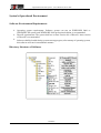
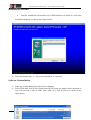
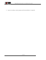
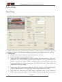
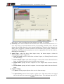
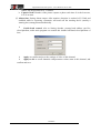
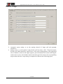
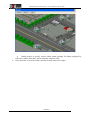
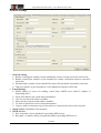
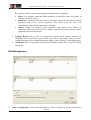
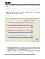
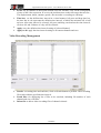
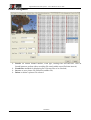
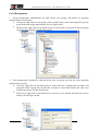
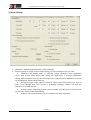
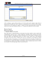
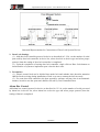
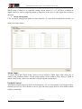
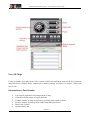
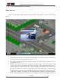
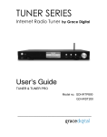
Digital Hard Disk Video System - User's Manual for Server Side Version V1.09 Digital Hard Disk Video System - User's Manual for Server Side November 2007 -2- Digital Hard Disk Video System - User's Manual for Server Side Table of Contents Chapter 1 Introduction to System.....................................................................................................1 System Functionality Features.......................................................................................................1 System's Operational Environment................................................................................................3 Hardware Environment..................................................................................................................4 Chapter 2 System Installations..........................................................................................................5 Hardware Installation.....................................................................................................................5 Software Installation......................................................................................................................5 Chapter 3 Operational Instructions for Software..............................................................................8 Running Software..........................................................................................................................8 Introduction to Functionality.........................................................................................................9 -3- Digital Hard Disk Video System - User's Manual for Server Side Chapter 1 Introduction to System System Functionality Features Server Running on a Windows 2000 or Windows XP platform, adopting state-of-the-art video and audio compression technique and involving few CPU resources, with the ability to ensure the long-term stability of the system; Simple, properly arranged and user-friendly interface; Full and practical functionalities ,without excessive utilities, abilities to satisfy users with monitor supervision requirements, and high system stability; Full capability of windows operation mode and e-map operator mode; and compatibility between e-map mode and window operation mode, without any impact to the connection of network users and reading of video information in any mode; Ability to define maps by user as required in case of e-map mode; Ability to support 4 types of video recording modes: continuous video recording, definite-time video recording, motion detection video recording, and alarming video recording; and ability of individual setup of each of the channel; Ability to support image shading; Ability to support full real time of max. 64 channels of images, with a frame rate for each channel of 25 frames per second (for PAL system) and 30 frames per second (for NTSC system); Ability to support 1, 4, 9, 16, 25 and 36 channels of multiframe split display , and group switchover of images; Image resolution ratio:CIF:352*288,HD1:704*288,D1:704x576; Ability to support alarming pre-recording and time-delay recording (time adjustable), recording the complete process of alarming video recording; No frame loss in switchover between files, completeness of video information ensured; Ability to support storage space of multiple hard disks, multi partition and automaticdetection of hard disk; Capacity of hard disk for recording: depending on a user adjustable code rate of video recording (i.e., compression ratio) , commonly code rate under compressed format of MPEG-4/H.264 is 60-225 Mbit/hour/channel, generally the setting value is 100 Mbit/hour/channel; Ability to superimpose such information as time and monitor supervision location to image frame; DVR4000 -1- Digital Hard Disk Video System - User's Manual for Server Side Ability to concurrently perform video recording, surveillance, playback and remote surveillance; Ability to support control of user authority, administrator can set up various operations for user(s); Functionality of software dongle, allowing the system to conduct self-diagnostics and self-protection, achieving unmanned; Ability to support voice talkback, and achieve voice talkback between multi-clientsides; Ability to support control operation of video camera PTZ (pivoting, translating, zooming and focusing), and decoder protocol being expandable through installation of driver; Ability to support door lock control, and control protocol is expandable through installing driver; Ability to support alarming linkage, alarm unit control protocol can be expanded through installing driver; Functionality of built-in HTTP network server, supporting network browsing (IE browsing) , providing plug-in units running on Internet. supporting mapping of dynamic state IP address to static state IP address or website; Providing common player and specialized player; Distinguishing features: e-map functionality Network talkback functionality Specialized playing functionality Network Network protocol: It supports TCP and UDP. User shall make options according to network conditions, ensuring higher transmission efficiency of video in various network environments; Ability to make retrieval by downloading index files from host computer, and supporting file play and network flow play; Ability to support multi-play operations, such as normal play, frame-by-frame play, fast forward play, slow speed play, single channel play, and multi-channel concurrent play; Ability to conduct PTZ control on video camera through network; Ability to support remote alarm Setup Guard and Remove Guard control; Ability to support remote voice talkback; and Ability of steady transmission of 1 channel real time image in 512Kbps ADSL network environment. DVR4000 -2- Digital Hard Disk Video System - User's Manual for Server Side System's Operational Environment Software Environment Requirements Operating system requirements: Software system can run on WINDOWS 2000 or WINDOWS XP system, and WINDOWS 2000 professional edition is recommended. DirectX requirements: The system shall use at least Version 8.0 of DirectX, latest version of DirectX is recommended. Software shall be loaded during system start-up progress, after startup of operating system, this software will run in an automatic manner. Directory Structure of Software DVR4000 -3- Digital Hard Disk Video System - User's Manual for Server Side Hardware Environment Requirements of Computer System CPU: at least Intel P4 1.4G , P4 2.5G CPU is recommended. Memory: at least 512 M, and 1G is recommended for system of more than 16 channels. Higher memory requirement is preferred for system intended for starting up network functions. Motherboard: since compression card and motherboard are closely related in their operations, noted motherboard with Intel series chipset is recommended on account of the preferable compatibility of motherboard with Intel chipset. Video adaptor: video adaptor shall support hardware stretching functionality, it is recommended to adopt display memory of at least 32M.Image quality depends on video adaptor used, therefore user shall select with care. Preferably GeForce or ATI video adaptors can be used, some integrated video adaptors are not supported. Users should make selections according to the practical situation. Sound card: sound card integrated on motherboard is available. Hard disk: high-capacity IDE or other hard disks with a rotational speed of 7200 rpm are recommended. For hardware installation requirements, refer to Hardware Installation Essentials. Hardware Abilities System supports protocol converter such that it is capable of converting various protocols or communication hardware characteristics into system identifiable protocols and communication hardware characteristics before being re-entered into the system; System is capable of access to cradle head decoder supplied by any manufacturer who can provide communication protocol, therefore implementing cradle head control functionality between local and remote ends; System is capable of access to any door lock controller of which the manufacturer can provide communication protocol; and System is capable of access to any alarm controller of which the manufacturer can provide communication protocol. DVR4000 -4- Digital Hard Disk Video System - User's Manual for Server Side Chapter 2 System Installations Hardware Installation Installation Procedure Installing basic components and operating system (drivers excluded) of computer Installing video compression card Installing motherboard driver Installing video adaptor driver Installation sound card and other drivers Installing DirectX of at least 8.0 version Installing peripheral equipment such as cradle head decoder, alarm controller, matrix, etc. Installation Precautions Peripheral equipment such as cradle head decoder and alarm controller shall be installed in accordance with its practical produce features. Non-compliance with said installation procedure may lead to system installation failure. To dissipate heat caused by hard disks installed in system, preferably the heat dissipation mode is such that air intakes from front face of computer and flows through power supply and cards, and vent holes are widened. In case of over heating in computer (exceeding 65), computer will likely malfunction, and boards/cards will likely malfunction, too. The file length compressed may be much greater than normal. In such a case the computer shall be shut down for cooling, awaiting improvement of CPU's fan and environmental temperature. Hard disk pertains to consumables that users shall buy on their own discretions. Software Installation Software Abilities Demo version: System runs without registration of video card, software of Demo version places restrictions on some software function, ex., unable to make video recording. Official version: The user registered software version, with full abilities of the software. Software is registered in such a manner that the number of the video card is encrypted. For specific procedure see Operational Instructions for Server Side Software. DVR4000 -5- Digital Hard Disk Video System - User's Manual for Server Side Installation Procedure Start the installation with double click of DVR 4000-Server-Setup.exe, and select installation language, as shown in the figure below: Select the default steps, i.e., Next, until installation is completed. Software Uninstallation Enter into Control Panel from Start menu on Desktop; Select DVR 4000 serial H.264 Capture board DVR system (the number herein depends on type of board/card, it may be 4400, 6400, 8400, etc.), click on Delete, as shown in the figure below: DVR4000 -6- Digital Hard Disk Video System - User's Manual for Server Side Operate according to system prompts until the uninstallation is completed. DVR4000 -7- Digital Hard Disk Video System - User's Manual for Server Side Chapter 3 Operational Instructions for Software Running Software Double click on desktop shortcut icon , or click on shortcut icon DVR 4000 from Applications of Start menu to enter software system. Under normal conditions, operating system will run server side software of this supervisory control system in an automatic manner. DVR4000 -8- Digital Hard Disk Video System - User's Manual for Server Side Introduction to Functionality Main Interface DVR4000 -9- Digital Hard Disk Video System - User's Manual for Server Side R.01 Logout. R.02 Login. A user shall use his own valid identity to log in. After login, the user will have operating authorization as allocated by administrator. When running the software for the first time, both default user name and password are admin (in lowercase). This user is of administrator authority. It is recommended to modify the password of user admin and add other operator users. In common cases, each user shall log in with his own user name assigned. See the figure below: R.03 System Log. It is used by user for viewing log information of various operations conducted on system.System provides functionality of current log and historical log viewings as well as log settings. Current log: intended for inquiry of operating records made within 24 hours, including occurrence time (running time) , name of user (log in user's name) and event (operating procedure), as shown in the figure below: Historical log: intended for user inquiry of historical operating records within storage time.One may select the date of log desired to view by time pulldown bar, the system will display the log of this day.See the figure below. DVR4000 - 10 - Digital Hard Disk Video System - User's Manual for Server Side Log settings: intended for setting saving time of historical operating records, as shown in the figure below, move the sliding bar, and the number of days will appear on the right side. R.04 Capture image. Intended to capture current image of selected frame. Continuous capture of multiple photographs can be implemented.After images desired to be captured are selected, click on this capture button, a capture image window appears showing the image captured. User may save or abandon according to image preview, the saving path can be set up on the settings page, the default storage path is X:\Capture (where X is the recording disk set by user). R.05 Hand operated video recording. Intended for startup of specified video camera to record. Select camera channel, click on this recording button to start recording, OSD of corresponding channel indicates red mark on the screen. Storage path of video recording information is X:\Record (where X represents the recording disk set up by user). R.06 Audio switch. Intended for On-Off of audio. R.07 E-map button. Intended for switching to e-map operation mode.See 3.2.3 for specific operations of e-map. R08 Playback video records. For details refer to Operating Instructions of Player. R.09 System settings (key part, which shall be configured by administrator). For specific information, see 3.2.2. R.10 Network management. Providing network online client-side userinfo, including IP address, user name, path way, online time, etc. Connection to client-side can be cut off actively from server side. R.11 Zoom ,Iris, Focus. Is it make a video recording diaphragm, focus, scale of device to regulate, in order to reach the best result of observing. R.12 Camera control. Intended for controlling cradle head (which is the unit supporting camera pick-up head)R.10 contains up, down, left, right, upper left, lower left, upper right, lower right 8 keys, each key controls cradle head to turn to corresponding azimuth. R.13 Alarm management. Intended for controlling the setup and withdraw of security protection of alarm box, and clearing alarm outputs, for details refer to 3.2.3.2. R.14 Fastball control. Intended for implementing the control of fastball cradle head and camera DVR4000 - 11 - Digital Hard Disk Video System - User's Manual for Server Side lens, and calling preset position, see 3.2.3.3 for details. R.15 Channel playback control area. Intended for splitting, grouping poll, display and full screen display of 1, 4, 9, 16, 25 and 36 frames. R.16 Company Logo. R.17 Help , Minimization ,Close. Others, Software information highlight: including current time display, display of user logged in, video recording hard disk partition display and software version display. DVR4000 - 12 - Digital Hard Disk Video System - User's Manual for Server Side System Setting Video Settings 1. Color: Adjust and select channel image's brightness, contrast, degree of saturation and tone, each pathway's image is independently adjustable. Commonly system default values are adopted. 2. Setting Video Channel: Select camera channel of which parameters are to be set; Name: Designate the selected channel camera; Image size: Select the resolution of video recording file from options of QCIF (low resolution), CIF (VCD resolution) and D1(DVD resolution), CIF is recommended for purpose of supervisory control. Higher resolution requires more hard disk space and broader bandwidth for network transmission, and therefore the cost of both storage and transmission will likely multiply. Image format: This system supports both PAL and NTSC formats, video standards applied in Chinese Mainland is PAL, and applied in Taiwan, Japan and Europe is NTSC. Image frame rate: video frame rate of PAL image is adjustable within 1-25 fps, and that of NTSC image is adjustable within 1-30 fps. Variation of frame rate has effect on continuity DVR4000 - 13 - Digital Hard Disk Video System - User's Manual for Server Side of image as well as the size of video recording file. 3.Setting Video Recording Media stream type: the options include Video Stream and Audio & Video Stream. When Video Stream selected, video records include image only, without sound; when Audio & Video Stream selected, video records include both image and sound. Key frame interval: It represents the interval of frame at which a key frame is included. The less the value is, the better the image result is, however, the greater the size of video recording file. Generally it is set to the default value, 100. Customized scheme: This system provides several customized schemes for user selection. Said customized schemes are Top Video Recording Quality, Superior Video Recording Quality, Generic Video Recording Quality, Inferior Video Recording Quality, Worst Video Recording Quality. Each scheme corresponds to a set of bit rate and quantized values, which can be adjusted by user on the basis of the scheme selected. In addition, the program also supports static state code stream (encoded in terms of fixed bit rate), dynamic state code stream (encoding bit rate adjusted on the basis of movement of image) and hybrid code stream (dynamic state encoding with upper limit of bit rate), user shall make the possible selection as required by practical environment, the general recommendation is hybrid code stream. 4. Other Settings OSD Enabled: to superimpose OSD information on image, including time, channel name and other information. Information superimpose starts when enabled; Preview Enabled: to enable the preview supervisory functionality of channel camera selected. Preview available when this is enabled. Network View Permitted: to view this channel of image at network client-side. Network view is available only when permitted; Stop record no video: When the camera video signal of the channel loses, stop the video automatically. After the signal resumes, begin the video automatically. Signal interruption alarm: Alarm is triggered when video signal of selected channel lost. Motion detection(displacement): DVR4000 - 14 - Digital Hard Disk Video System - User's Manual for Server Side (1) Del ay: The delay time of video recording after alarm triggered is within 1-5 seconds. (2) Sensitivity: Set a desired motion detection area (max. full screen detection area is 11 * 9) in video image of selected channel and the corresponding sensibility value, when the motion of area under detection varies (image brightness of detection area changes), the alarm will be triggered. If motion variation is not detected by the system, it means the sensibility value has not been properly set, reset it as appropriate. the less this value is, the higher the sensibility is. (3) Alarm Type: (when the above alarm input occurs, the alarm output as shown in following figure can be triggered): Send an e-mail: send an e-mail when an alarm is input, see Setting Network section for mail settings; Send to alarm center: send alarm message to remote alarm centre when an alarm is input, see Setting Network section for alarm centre settings; Sound alarm: prompt on local computer in voice output mode when an alarm is input; Screen alarm: prompt on local computer in screen output mode when an alarm is input; (4) Capture Setting: Capture: Setting capture photos when receive alarm message. Capture Delay: Interval while capture a photo twice. This interval does not regard time as the unit, but count as the unit with the frame. The minimum interval is 5 DVR4000 - 15 - Digital Hard Disk Video System - User's Manual for Server Side frames, the largest interval is 15 frames. Capture Num: Number of the picture capture a photo each time. It is the least one, it is 10 at most. (5) Alarm Out: Setting Alarm output. After monitor detection is touched off, if link and establish while be exporting, systematic will touch off the warning device (mainly a warning box) among them automatically . Cradle head control: refer to Setting decoder, protocol and address yard for cloud platform, make main program can control this channel affiliated cloud platform of lens; Apply: to confirm and save the settings of video of this channel; Apply to all: to set all channels with parameter values same as this channel, and confirm and save. DVR4000 - 16 - Digital Hard Disk Video System - User's Manual for Server Side General Settings Automatic repeat setting: to set the spacing interval of image poll and grouping switchover; Setting e-map: to set the path of e-map which is a 24 bit-colour, 1024 * 768 pixel-element bit map, user shall customize it when in use; click on the setting button on the right-hand side, a window as shown in the figure appears, press left button of the mouse and drag the camera icon to move each channel camera from the upper left corner to the corresponding map position, then the e-map setting is completed, as shown in the following figure. DVR4000 - 17 - Digital Hard Disk Video System - User's Manual for Server Side Setting sound: to specify various alarm output prompts for alarms triggered by video loss, motion detection, alarm controller, and door lock ; Voice intercom: to specify sound card unit for mike and voice output. DVR4000 - 18 - Digital Hard Disk Video System - User's Manual for Server Side Network Settings 1. Network settings Remote viewing port: number of port intended for remote viewing at network's client side; Remote control port: number of port intended for remote connection control at network's client side; Download port: number of port intended for remote file download at network's client side; Talk port: number of port intended for voice talkback at network's client side. 2. E-mail Settings SMTP: address of server for sending e-mail (Note: SMTP server shall be capable of forwarding mail) ; From: mail address who sends alarm information; User: the account with sender’s mailbox; Password: the password with sender’s mailbox; To: mail recipient who receives alarm information; Copy to: make a concurrent copy for the mail to a recipient when sent to this recipient; 3. Alarm Center (forbidden for the moment) 4. WWW Service Port: set number of port intended for providing WEB service; Root path: set master catalog root path intended for providing WEB service. DVR4000 - 19 - Digital Hard Disk Video System - User's Manual for Server Side 5. DNS Server Configure Start DNS Server: Should set up after serving, the client can be analyzed to controlling the server name through the special name server, obtain its IP address that is using. Enable the client to only need to know the server name can be connected with server, needn't remember constantly changeable IP. DNS Address: The server is in IP address of WAN or the LAN. Server Name: Server name. User , Password: The account and password which will upgrading to the special name server the server address and name. Peripheral Device Device list: list the peripheral devices connected to serial ports COM 1 and COM2, including device type (decoder, door lock controller and alarm box) and device protocol; Device: to add control protocol to various serial port devices, just right click on device type (ex., decoder), select protocol to be added in menu appeared, and specify the protocol driver path according to prompts. DVR4000 - 20 - Digital Hard Disk Video System - User's Manual for Server Side Gpio Setup DVR4000 - 21 - Digital Hard Disk Video System - User's Manual for Server Side 1. Gpio: If already a bunch of resources and warning box agreements have been correlated with connecting with in outside equipment, in the additive warning box equipment here. Add: Add new Gpio. Delete: Delete an existing Gpio. Modify: Modify the setting of Gpio. It is that the warning box adds interfaces to have pictures. Including: Name: This name will appear in other servers will be set up. SerialPort: Correlated with one bunch of resources connected with the warning box agreement with in the outside equipment. This please keep the same with establishment in the outside equipment to establish. Address Code: Establish eight digits of the address on the warning box. About how revise address yard, please consult warning box operation instructions. Alarm In/Out: Different according to warning box specifications which each producer produces, can be divided into and entered eight, entered 16, 16 and entered 16,etc. 2. Alarm In: Namely receive the interface of the alarm message in the warning box. Each alarm in the corresponding alarm is input is clicked, can all link the video and report to the police to export establishing alone. DVR4000 - 22 - Digital Hard Disk Video System - User's Manual for Server Side 3. Linkage Record: Set up how is it report to the police incident of inputting to respond. Including video, send E-mail, screen alarm, voice alarm, report alarm centre to, take a candid photograph, take a candid photograph number, time of taking a candid photograph. 4. Alarm Out: Set up the alarm how the warning output end responds the warning input end and click and touch off the warning incident. Door Setup 1. Door: If already a bunch of resources and entrance guard's agreements have been correlated with connecting with in outside equipment, in the additive entrance guard's equipment here. Add: Add new door. Delete: Delete an existing door. Modify: Modify the setting of the door. DVR4000 - 23 - Digital Hard Disk Video System - User's Manual for Server Side Have picture whether entrance guard equipment add interface. Including : Name: Give entrance guard that adds equipment to name.This name will appear in other servers will be set up. SerialPort: Correlated with one bunch of resources connected with entrance guard's agreement with in the outside equipment. This please keep the same with establishment in the outside equipment to establish. Address Code: The entrance guard establishes eight digits of the address on equipment. About how about revise the address yard, please consult entrance guard's equipment operation instructions. 2. 3. Linkage Record: Set up how to respond the entrance guard incident touched off. Including video, send E-mail, screen alarm, voice alarm, report alarm centre to, take a candid photograph, take a candid photograph number, time of taking a candid photograph. Alarm Out: How to respond the entrance guard incident touched off to set up the warning output end. Disk Management Video recording disk: set the selected partition as video recording file storage partition, the DVR4000 - 24 - Digital Hard Disk Video System - User's Manual for Server Side storage path of video recording file is X:\record, where X is the disk partition selected herein. Several video recording disk partitions hereof can be selected, it is recommended not to select disk C. Capture image disk: set the selected partition as capture image storage partition, the storage path of video recording file is X:\Capture, where X is the disk partition selected herein. Several video recording disk partitions hereof can be selected, it is recommended not to select disk C. Refresh video records: rearrange video recording data, delete error video files due to improper shutdown, and make the video recording data correspond to data base index records. Rearrangement starts after clicking on refresh. Schedule Setup Channel: set definite-time video recording schedule of channel camera, select various channels from drop-down list. Schedule: Set up the arrangement of time that the channel carries out the timing video function at present. Motion: Set up channel in detect and examine after the displacement incident, carry on the arrangement of time of the video at present. If the displacement incident happens outside the time range that sets for, do not carry on the video. Alarm : Set up channel in is it examine get warning box incident to detect, carry on the arrangement of time of the video at present. If the alarm incident happens outside the time range that sets for, do not carry on the video. DVR4000 - 25 - Digital Hard Disk Video System - User's Manual for Server Side Event: Set up channel in detect and examine after the incident, carry on the arrangement of time of the video at present. If receive the incident outer on the time range that sets for ( The displacement, alarm, entrance guard) ,Do not make a recording on videotape. Time bar: set the definite-time interval in a visual manner, left press and drag time bar, the time bar in red represents the definite-time interval, of which the minimal cell is half an hour. After time interval is selected, left press and drag can deselect the time interval; click on All, and 24 hours of a day will be selected. Apply: save the definite-time interval setting of selected channel; Apply to all: apply the time interval setting to all camera channels and save. Video Recording Management Search: set starting time and end time, click on Search button to perform video recording file search within a specified time interval; Listed files: for displaying list of files to be searched, including file number of each channel and size of all files; Delete file: to delete video recording files of channel selected. DVR4000 - 26 - Digital Hard Disk Video System - User's Manual for Server Side Picture Management Search: set camera channel number, event type, starting time and end time, click on Search button to perform video recording file search within a specified time interval; Listed files: intended for displaying list of picture files to be searched; Save as: to save picture file selected as another file; Delete: to delete a picture file selected. DVR4000 - 27 - Digital Hard Disk Video System - User's Manual for Server Side User Management 1. Group management: administrator can add various user groups, and define an operating authorization for each group. Add group: right click on user group, click on Add Group on the menu appeared, specify group name and assign authorization. See the figure below. Delete group: right click on specified group to select group to be deleted, then the group selected can be deleted. See the figure below. 2. User management: intended for add and delete user for group, user has the same operating authorization as group. Add user: right click on specified group to select Add User, complete the user name and password to add a group user. System user is unique, no user name shall be the same even in different groups. See the figure below. Delete user: right click on specified user to select user to be deleted, then this user can be deleted. See the figure below. DVR4000 - 28 - Digital Hard Disk Video System - User's Manual for Server Side DVR4000 - 29 - Digital Hard Disk Video System - User's Manual for Server Side System Settings IP address: indicating the IP address of this computer; Restart system: to set the system restart strategy of host computer at server's side; Shutdown and startup mode: If selecting system shutdown while application closes, then system shuts down when exiting the application; if selecting application startup while computer starts up, then this supervisory control system application will start up automatically when system starts up. Prompt message: if this option is selected, when remote client accesses or logs on with a card through door lock system, a prompting message window will pop up, otherwise no prompt appears. Remote update: displaying current version number, presently this version does not provide any remote update functionality. Register: all system functions can be available only after registered. DVR4000 - 30 - Digital Hard Disk Video System - User's Manual for Server Side Click on Register, system will list numbers of all video cards in this computer, single click on Export, this card number file will be exported to a specified text file, as shown in above figure. Send this file to the company for register, a register-file will be generated, and user copies this register-file to Reg under installation folder (ex., C:\Program Files\Boanson\GVS\Server\Reg). Device Control Door lock Control 1. Structure of Door Lock System Door lock system is composed mainly of card reader, door lock controller, electric control lock, communication converter and PC control mainframe (including control software).Card reader herein is designed for collecting user identity information; door lock controller is designed for data input and output, and implementing unlock IO control; electric control lock is the actuating mechanism of door lock system; communication converter is designed for converting RS 232signal into RS 485 signal, for the purpose of remote transmission and bus networking of multiple door lock controllers; PC controlled mainframe communicates with door lock controller, for the purpose of identifying user identity and sending corresponding control command (open the door) to door lock controller. The following figure shows its system structure: DVR4000 - 31 - Digital Hard Disk Video System - User's Manual for Server Side Structural Representation for Connections of Door Lock System Devices 2. Door Lock Settings (1) Add door lock controller protocol in device as described in 3.2.2.4, set the number of serial port used by door lock controller in device list, select door lock as device type and select proper protocol, then the setting of door lock controller is completed. (2) Upon the completion of setting door lock controller, single click on Door Lock button on main interface of system to implement open/ close the door once. 3. Precautions (1) Electric control lock can be divided into anode lock and cathode lock, therefore attention shall be fixed to wiring during installation of lock so as not to connect the lock inversely. (2) For some door lock controllers, the door opened by software will not close in an automatic manner, in such a case the open state shall be relieved by Card Controlled Door. Alarm Box Control Add alarm box control protocol in device as described in 3.2.2.4, set the number of serial port used by alarm box in device list, select alarm box as device type and select proper protocol, then the setting of alarm is completed. DVR4000 - 32 - Digital Hard Disk Video System - User's Manual for Server Side When setting of alarm box is completed, setting various alarms in 3.2.2.1 will allow its linkage to output alarm box, such as triggering output of alarm box in the cases of video signal loss or motion detection. Alarm Management Click on Alarm Management button on main interface,, to enter alarm management interface, as show in the figure below: Alarm Input: To control alarm box. Select Setup Guard to set up control of alarm input, when alarm box in control setup condition alarms, relevant alarm output will be enabled; Select Remove Guard to cancel control setup, in this case alarm box will not respond to alarm input.. Fastball Control Add fastball control protocol in device as described in 3.2.2.4, set the number of serial port used by fastball in device list, select decoder as device type and select proper protocol, then fastball control setting is completed. DVR4000 - 33 - Digital Hard Disk Video System - User's Manual for Server Side Use of E-Map E-map is another operating mode of the system, which can implement most of the key functions under the above window mode, without any complex settings, therefore it is simple, visible and easy to use. Introduction to Functionality Lay out pick-up head in relevant position of map; View the real time image of a pick-up head; Conduct capture of pictures and video recording from a pick-up head; Exercise control on pick-up head cradle head and camera lens; Door Lock Control: Alarm control; and DVR4000 - 34 - Digital Hard Disk Video System - User's Manual for Server Side View network management information. Main Interface Click on e-map button under window mode to enter e-map mode, as shown in the figure below: User shall set up path of e-map picture and location of each video camera in map under window mode, for specific operations, refer to 3.2.2.2. For display contents of each area below the window and usage of function buttons, refer to descriptions in 3.2.1. Double click video camera icon in map, a real time image of this video camera will appear, then proceed to capture and video recording of this channel of image in the window appeared, as shown in the above figure. Double click multiple video camera icons will open a number of windows, implementing real time monitoring of multi-channel image, however, in such a case image display windows of all channels of video camera are at the same position, the images are all superimposed, resulting in flickering window frame. This superimposition may disappear by dragging windows with mouse to different DVR4000 - 35 - Digital Hard Disk Video System - User's Manual for Server Side positions. DVR4000 - 36 -