1
MANUAL NO. OPS112-UM-155
USER'S MANUAL
SOFTWARE LICENSE AGREEMENT
Graphtec Corporation ("Graphtec") permits you to use the software distributed together with this
agreement ("Software") based on the terms and conditions prescribed below, and you shall also
agree to be bound by such terms and conditions before you may use the Software.
1. Copyrights
Each of the copyrights of the Software and all the information contained in the printed documentation such as manuals, distributed together with the Software, is owned by the individual or
corporate body indicated in the Software or the appropriate documentation.
2. Right of use
You may install and use one copy of the Software on one computer at a time.
3. Duplication or Modification
(1) You may duplicate the Software for backup purposes only. In this case, the right (i.e.,
copyright) that covers the Software must be displayed in every duplication.
(2) You shall not disassemble or decompile the Software in order to merge, amend, or adapt it
in any way.
4. Use by third parties
It is a contravention of the license agreement to permit a third party to use the Software, or
transmit or transfer it to a third party, or otherwise dispose of it for a third party.
5. Warranty
(1) If the Software cannot be operated normally due to physical failure of the storage media,
contact your Graphtec vendor. If the physical failure is due to a fault of Graphtec, the storage media will be replaced free of charge.
(2) The replacement in the above paragraph is the only warranty undertaken by Graphtec.
(3) Graphtec supplies the Software "as is". Graphtec or the supplier does not warrant any
performance or results obtained through use of the Software or the documentation accompanying it. Either expressly or implicitly, Graphtec or the supplier does not warrant any
absence of invasion of the right of a third party, merchantability, and/or fitness for a particular purpose. In whatever case, Graphtec or the supplier assumes no responsibility for
incidental, derivative, or special damages, even if the Graphtec vendor has notified the user
of the possible occurrence of such damages. In addition, Graphtec or the supplier assumes
no liability for rights asserted by a third party.
Scanning Master 21+
i
ABOUT THE REGISTERED TRADEMARKS
◆ Any company or product name in this manual is the registered trademark or trademark of
the respective company.
◆ All copyrights of Scanning Master 21+ software and this manual are owned by Graphtec.
NOTES
◆ While image data is being scanned using Scanning Master 21+, it is mandatory that no
other scanning-in software be operated concurrently.
◆ To output data to a plotter or printer using Scanning Master 21+, you must have a plotter
that supports raster printing.
◆ To output a long-length document on a plotter by using Scanning Master 21+, you must
have a plotter that supports long-length printing of raster data.
When using the USB interface
◆ Requires a USB 2.0 interface.
When using the IEEE 1394 interface
◆ Requires an IEEE 1394 interface.
CAUTIONS AND CONDITIONS CONCERNING THIS MANUAL
◆ The whole or part of the contents of this manual may not be duplicated or reproduced
without the permission of Graphtec.
◆ The contents of this manual and the specifications for the product are subject to change
without prior notice.
◆ We have made every effort to guarantee the contents of this manual and product; however,
should you find any unclear information or possible errors, please contact Graphtec or your
Graphtec vendor.
◆ Graphtec assumes no liability with respect to this manual or for any effect arising from
operating the product even if the manual contains any unclear information or possible errors
as mentioned in the previous paragraph.
Scanning Master 21+
ii
CONTENTS
1. INTRODUCTION
1.1
1.2
1.3
Preface ................................................................................................................. 1-1
Features ................................................................................................................ 1-1
Operating Environment ......................................................................................... 1-2
2. SETUP
2.1
Installation ............................................................................................................. 2-1
3. OPERATIONS
3.1
3.2
3.3
3.4
3.5
Setting Up the Scanner ......................................................................................... 3-1
Scanning Procedure ............................................................................................. 3-2
Scan Settings ........................................................................................................ 3-3
Scan and Print .................................................................................................... 3-20
Scanner Adjustment ........................................................................................... 3-21
4. IMAGE DATA MANIPULATION
4.1
4.2
4.3
4.4
4.5
4.6
4.7
Window Overview ................................................................................................. 4-1
Basic File Operations ............................................................................................ 4-4
Printing Image Data .............................................................................................. 4-6
Viewing the Image ................................................................................................ 4-7
Using the Edit Functions ..................................................................................... 4-12
Other Image Editing Functions .......................................................................... 4-19
Image Measurement ........................................................................................... 4-29
5. DESCRIPTIONS OF FUNCTIONS
5.1
5.2
5.3
Options Settings ................................................................................................... 5-1
Menus ................................................................................................................... 5-5
File Formats ........................................................................................................ 5-11
INDEX .......................................................................................................................... Index-1
Scanning Master 21+
iii
1. INTRODUCTION
1.
INTRODUCTION
1.1
Preface
The Scanning Master 21+ driver software scans in image data through the scanner and displays
it, allowing you to edit the scanned-in image.
1.2
Features
Improved Productivity with an Enhanced Scanner Driver
You can perform all scanning settings for the scanner through the Scanning Master 21+ scanner driver. The conditions of the drawing may vary significantly. However, it is easy to select the
resolution and make fine adjustments when setting the threshold according to various document
conditions (e.g., diazo copy, yellowed drawings).
Scanning Functions to Implement Sharp Input
Using the Rocker Mode, you can determine the most appropriate settings while repeatedly
scanning in a specific section of the input image and reviewing the scanned-in image.
Threshold Adjustment
You can make the settings as detailed as is appropriate for the intended use (e.g., settings
related to black/white inversion, halftones, brightness, and threshold).
Variety of Edit Functions
With despeckling, speckles smaller than the specified size can be erased. With deskewing, any
skew in the scanning operation can be corrected horizontally. Other functions such as copy,
paste, area erase and rotate are also available.
Note: Editable functions may be different, depending on the data type (grayscale, 8-bit color, 24bit color, bilevel).
Supports a Wide Range of File Formats
Scanning Master 21+ supports a wide range of file formats:
Bilevel:
Bitmap, CAD Overlay ESP, TIFF Uncompressed, TIFF G4, TIFF Packbits,
TIFF CCITT G3, TIFF G3, CALS G4, PCX, INTERGRAPH G4, Sun Raster
Uncompressed, Sun Raster Encode, PDF*1
Grayscale:
Bitmap, Bitmap RLE, TIFF Uncompressed, TIFF Packbits, TIFF JPEG, PCX,
Sun Raster Uncompressed, Sun Raster Encode, JPEG, PDF*1
8-bit color:
Bitmap, Bitmap RLE, TIFF Uncompressed, TIFF Packbits, PCX, Sun Raster
Uncompressed, Sun Raster Encode, PDF*1
24-bit color:
Bitmap, TIFF Uncompressed, TIFF Packbits, TIFF JPEG, PCX, Sun Raster
Uncompressed, JPEG, PDF*1
*1 For saving data only
Scanning Master 21+
1-1
1. INTRODUCTION
1.3
Operating Environment
The minimum system requirements for operation of the scanner hardware and software are
listed below:
System Requirements
◆ OS
◆
◆
◆
◆
◆
◆
◆
◆
: Windows 2000 Professional, Windows XP Professional/Home Edition, Windows Vista
We do not have plan to comply with the Windows (64bit version).
(The NTFS filesystem is necessary to preserve the file in 4G byte or more.)
CPU
: Pentium 133 MHz or higher grade
Memory : 32 MB or more
Monitor : 1024 × 768, 256 colors or more
Disk space amount that can contain the scanned-in data
Mouse
Network interface : 10BASE-T/100BASE-TX (to connect the scanner via the Network interface)
USB interface (to connect the scanner via the USB interface*1)
IEEE 1394 card (to connect the scanner via the IEEE 1394 interface*2)
*1 If your scanner does not operate with the USB interface that comes with your computer, or if your
computer does not have a USB 2.0 interface, please contact your sales representative or nearest
Graphtec vendor for information on supported add-on cards.
*2 Graphtec does not guarantee correct scanner operation with every IEEE 1394 computer interface or
add-on card. Please contact your sales representative or nearest Graphtec vendor for information on
supported add-on cards.
*3 When using this driver software on the Windows Vista, please logon as the administrator. If you logon
as the general user, some functions are limited.
Recommended Environment
For bilevel data:
◆ CPU
: Pentium 200 MHz or higher grade
◆ Memory : 64 MB or more
◆ Network interface : 100BASE-TX (to connect the scanner via the Network interface)
◆ USB 2.0 interface (to connect the scanner via the USB interface)
For grayscale:
◆ CPU
: Pentium III, 550 MHz or higher grade
◆ Memory : 256 MB or more
◆ Monitor : 1024 × 768. Must support High Color display.
◆ Network interface : 100BASE-TX (to connect the scanner via the Network interface)
◆ USB 2.0 interface (to connect the scanner via the USB interface)
For 8-bit/24-bit color:
◆ CPU
: Pentium III, 866 MHz or higher grade
◆ Memory : 512 MB or more
◆ Monitor : 1024 × 768, True Color display
◆ Network interface : 100BASE-TX (to connect the scanner via the Network interface)
◆ USB 2.0 interface (to connect the scanner via the USB interface)
1-2
Scanning Master 21+
1. INTRODUCTION
Checkpoint
To satisfy the specification for the scanning speed, use hardware of the recommended grade or
higher. For a monitor with 256 or fewer colors, scanned-in images may be unable to be displayed
in the original colors. If you want to scan in and edit grayscale or color data larger than A1 size,
400 dpi, you may need a memory larger than the recommended size.
Depending on the document, it may not be possible to scan in the images it contains or the
process may slow down even if the memory size is increased.
If you encounter such a problem, select "Tools" > "Options" > "General" tab and enable "Use
Work File". In addition, enable "Specify Folder" and then specify a folder that contains sufficient
available space.
Compatible Scanners
◆ The following Graphtec scanners are compatible:
CS300 Series
CS400 Series
CS500 Series
CS510 Series
CS600 Series
CS610 Series
IS200 Series
IS210 Series
SK200 Series
CSX300 Series
Checkpoint
For details, see the README.TXT file.
For details on how to connect your scanner to your computer, please refer to your scanner’s
User’s Manual.
Scanning Master 21+
1-3
2. SETUP
2.
SETUP
2.1
Installation
The Scanning Master 21+ software is designed to scan in image data through a Graphtec
scanner.
Setup Procedure
(The description below is for Windows 2000.)
(1) Start Windows.
(2) Insert your scanner’s User Guide CD-ROM into the CD-ROM drive slot.
(3) In the Start menu, select Run.
(4) In the Run dialog box, type the CD-ROM drive letter followed by
"English\OPS112\SETUP.EXE".
(5) Once you click the OK button, the Scanning Master 21+ setup program starts. Next, follow
the instructions of the setup program to perform the setup.
Note: Once the setup program terminates normally, "Scanning Master 21+" is added to the
Programs menu in the Start menu.
Scanning Master 21+
2-1
3. OPERATIONS
3.
OPERATIONS
3.1
Setting Up the Scanner
(1) Make sure that the scanner is connected to the computer and the power to it is off. Then
power on the scanner.
(2) Power on the computer.
(3) Windows starts up.
(4) Locate the Scanning Master 21+ icon. To do so, click the Start button and select Programs
and the Scanning Master 21+ folder in that order. The icon is found there.
(5) Click the Scanning Master 21+ icon.
(6) If you run Scanning Master 21+ for the first time, use the Model Setup in the Scan menu to
specify the scanner currently connected to the system.
Checkpoint
Although Scanning Master 21+ lets you set the same items regarding the View window regardless of scanner model, it requires you to set different items regarding the Scan window, depending on the scanner model. Be sure to select the scanner model.
Scanner ................... Set the model of the scanner through which image data is scanned in.
Interface ................... Select the interface used to connect the scanner to the computer.
Confirm button ........ Use this button to confirm that the scanner is connected. If a scanner is
connected, its name and version number are displayed.
(7) Select the Scan command from the Scan menu, or click the Scan button in the Scan Tools
sub-window, or click the Scan button on the toolbar to display the window for performing
scanning by the scanner.
Scanning Master 21+
3-1
3. OPERATIONS
3.2
Scanning Procedure
Select the Scan command from the Scan menu, or click the Scan button in the Scan Tools
sub-window, or click the Scan button on the toolbar to display the Scan window.
To scan the document, simply select the document type in the Scan window and then click the
Scan button. For further details on the Scan window settings, please refer to Section 3.3,
"Scan Settings".
Scan settings are preset for each document type. You can add, modify or delete document
types as required.
To add or modify a document type
(1) Select the Scan command from the Scan menu, or click the Scan button in the Scan Tools
sub-window, or click the Scan button on the toolbar.
(2) Change the settings in the Scan window. Prescan and preview the document to set the
optimum scan conditions.
(3) Click the Save... button to name and save the scan settings.
(4) The saved scan settings are added to the document types.
To delete a document type
(1) Select the Scan command from the Scan menu, or click the Scan button in the Scan Tools
sub-window, or click the Scan button on the toolbar.
(2) In the Scan window, select the document type you want to delete, and then click the Delete
button.
(3) The specified scan settings are deleted from the document types.
3-2
Scanning Master 21+
3. OPERATIONS
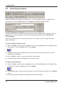
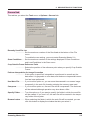
3.3
Scan Settings
Checkpoint
Scanning Master 21+ may not permit you to select or specify some of the Scan Settings,
depending on the scanner model that you have.
For details on connecting your scanner to your computer, please see your scanner’s User’s
Manual.
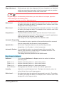
Scan Button ............ Performs scanning using the specified settings.
Prescan Button ....... Performs a prescan operation. The Prescan mode lets you set the scanning conditions most suitable for the document while the scanner is
actually in operation.
Using the Rocker Mode, you can change the scanning conditions while
scanning in the same section repeatedly; you should set the optimal
scanning conditions while reviewing the on-screen image quality. Then
perform the actual scanning.
Scanning Master 21+
3-3
3. OPERATIONS
Use the following procedure for operation:
(1) Press the Prescan button to initiate scanning.
(2) Continue scanning up to the section for which you want to set the
scanning conditions. If the image is currently displayed in the Preview Window, move the mouse cursor to the section for which you
want to set the scanning conditions. Left-click there to move the
scanning position to a previous one.
(3) Once the scanning position has been moved, turn on the Rocker
Mode at any position to scan in data repeatedly from the same
position. At this time, while reviewing the on-screen image in the
Preview or Details Window, you can set the optimal conditions by
changing the scanning settings.
(4) Once you have set the optimal conditions, quit the Prescan Mode and
run Scan.
This setting cannot be specified for the SK200 model.
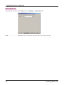
Preview .................... Performs scanning using the specified settings, and displays the results
in the Preview window. Left-click on any part of the Preview window to
display that area in the Details window. To change the size of the display, click on the buttons in the Preview window. Scanning is performed
at the 1:1 setting.
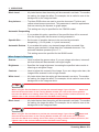
Output ...................... Specify how the scanned-in image data is to be processed.
Bilevel .................. Data is scanned in at two levels of black and white. Suitable for scanning
in line drawings or characters.
Halftones ............. Data is scanned in at two levels of black and white. During scanning, one
of four halftone methods is used to perform halftone processing.
Grayscale ............ Data is scanned in as an eight-bit image that contains a 256-level gray scale.
Suitable for scanning in a monochrome photograph or similar document.
8-bit color ............. Data is scanned in as an eight-bit color image.
24-bit color ........... Data is scanned in as a 24-bit color image.
Document Type ....... Specify the type of document. Also specify any settings that are to be
saved/read.
Save… Button ......... Saves the scan settings under a new file name. The saved settings can
be read in Document Type.
Delete Button .......... Deletes the currently selected Document Type from the list.
Defaults Button ....... Loads the default settings for the specified Document Type.
Tip
Settings entered at Output and at the Document, Adjustments, File, Options, and Mail tabs are
saved as scan conditions.
3-4
Scanning Master 21+
3. OPERATIONS
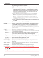
Document Tab
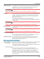
Paper Size ............... Select the size of the document that contains the image data you want to
scan in. If you want to supply a user-defined paper size here, type in the
width and length of the document.
When automatic detection of document size is enabled
Automatic detection .............................. The scanner automatically detects the dimensions of
the document to be scanned.
This setting cannot be specified for the CSX300
model.
Automatic detection of standard size ... The document is scanned so that its length and
width proportions automatically fit within the borders
of the set paper size.
This setting cannot be specified for the CSX300
model.
Automatic detection—ISO series ......... This setting cannot be specified for the CSX300
model.
Automatic detection—ISO A series ...... This setting can only be specified for the CSX300
model.
Automatic detection—ISO B series ...... This setting can only be specified for the CSX300
model.
Automatic detection—ANSI series
Automatic detection—ARCH series
Automatic detection—DIN series ......... The document is scanned so that its length and
width proportions automatically fit within the borders
of the paper size of each series.
All automatic detection cannot be specified for the
SK200 model.
Orientation .............. Select the orientation of the document that contains the image data you
want to scan in.
Resolution ............... Specify the resolution at which image data is scanned in.
Quality ..................... Specify the sacn quality at which image data is sanned in.
This setting cannot be specified for the CS300/400 model.
Fast Scan ................. Scans and feeds documents at up to twice normal speed. The scanned
image data may be somewhat coarse compared to normal scans.
This setting can only be specified for the CS300/400 model.
Initial X Position Initial Y Position
.................. Let you move the start position so that you can skip over any white
margins at the edge of the document.
This setting cannot be specified for the SK200 model.
Paper Size after Scan
.................. After the document has been scanned, the document is enlarged or
reduced to a specified paper size without altering its height to width ratio.
Scanning Master 21+
3-5
3. OPERATIONS
End-of-paper processing
.................. Specifies the processing to be performed when the scanner has detected
the end of the paper during scanning.
Confirm ................ Displays a window for confirming whether or not to create an image all
the way up to a specified paper size.
End of paper ........ Creates the image all the way up to the position at which the end of the
paper was detected.
Paper size ........... Creates an image all the way up to a specified paper size.
Rotate ...................... The image will be rotated after scanning.
Mirror ....................... If you enable this option, the image will be inverted on the vertical axis
after scanning.
Negative ................... If you enable this option, the image will be color-inverted after scanning.
Document Thickness
.................. Displays the thickness of the document during scanning.
This setting can be only displayed in the CS600/610 model.
Adjustments tab
Rocker Mode ........... If you enable this option, you can change the scanning conditions while
scanning the same section repeatedly; you should set the optimal scanning conditions while reviewing the on-screen image quality. Then perform the actual scanning.
This setting cannot be specified for the SK200 model.
Tip
Rocker Mode is available only for prescanning.
Once the scanning position has been moved, you can turn on the Rocker Mode at any position
and scan in data repeatedly from the same position.
With the image displayed in the Preview window, move the mouse cursor to the area for which
you wish to make the settings for scanning, and then right-click to return the scanning position
to a previous position and turn on the Rocker mode.
You can turn the Rocker mode off if you right-click in the Preview window when in Rocker mode.
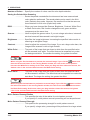
When Output is Bilevel
Intensity ................... Adjusts the overall brightness level. The higher the Intensity value, the
whiter (fainter) the overall image appears.
Intensity Correction
.................. Specify the degree of correction that applies to auto adjustment of the
difference in contrast between the foreground and background.
If the value is 0 (zero), only Brightness (Intensity) is available. The larger
the value, the greater the effect on documents with contrast. Note that setting
an excessively large value here is likely to generate noise or speckles.
3-6
Scanning Master 21+
3. OPERATIONS
Edge Adjustment .... Setting a larger value here sharpens thin lines, characters, etc. Note that
setting an excessively large value is likely to generate noise or speckles
at each boundary between a black and a white area.
Tip
If a good image is not obtained by default when you select “Bilevel” for Output, adjust the
control settings in the following order:
Intensity > Intensity Correction> Edge Adjustment
White Level .............. All pixels whiter than the setting will be scanned in as white. The smaller
the setting, the larger the effect. For example, this is useful to scan in the
background on the image as white.
Black Level .............. All pixels blacker than the setting will be scanned in as black. The smaller
the setting, the larger the effect. For example, this is useful to scan in the
background on the image as black.
Gray balance ........... The three RGB colors are used to scan the document. The blue and
yellow colors become prominent. This parameter is used for applications
such as scanning the squares on graph paper.
This setting can only be specified for the CSX300 model.
Automatic Despeckling
.................. If you enable this option, speckles of the specified size will be removed
from the image while the document is being scanned in.
Speckle Size ............ Set the size of speckles that are to be removed by automatic
despeckling. (1 to 30 pixels, in 1-pixel increments)
Automatic Deskew .. If you enable this option, any skewed image will be corrected if the
scanner gets scanned-in image data from a skewed document. The
automatic deskew operates up to ±7.1°.
This setting cannot be specified for the SK200 model.
When Output is Halftones
Halftones ................. If you selected Halftones for Output, select the method of halftone
processing here.
Dither 4 × 4 .......... Halftone processing with a 4 × 4 dot matrix pattern.
Dither 4 × 8 .......... Halftone processing with a 4 × 8 dot matrix pattern.
Dither 8 × 8 .......... Halftone processing with a 8 × 8 dot matrix pattern.
Error Diffusion ..... Photographs are scanned in with a more natural appearance.
Intensity ................... Adjusts the overall brightness level. The higher the Intensity value, the
whiter (fainter) the overall image appears.
White Level .............. All pixels whiter than the setting will be scanned in as white. The smaller
the setting, the larger the effect. For example, this is useful to scan in the
background on the image as white.
Scanning Master 21+
3-7
3. OPERATIONS
Black Level .............. All pixels blacker than the setting will be scanned in as black. The smaller
the setting, the larger the effect. For example, this is useful to scan in the
background on the image as black.
Gray balance ........... The three RGB colors are used to scan the document. The blue and
yellow colors become prominent. This parameter is used for applications
such as scanning the squares on graph paper.
This setting can only be specified for the CSX300 model.
Automatic Despeckling
.................. If you enable this option, speckles of the specified size will be removed
from the image while the document is being scanned in.
Speckle Size ............ Set the size of speckles that are to be removed by automatic
despeckling. (1 to 30 pixels, in 1-pixel increments)
Automatic Deskew .. If you enable this option, any skewed image will be corrected if the
scanner gets scanned-in image data from a skewed document. The
automatic deskew operates up to ±7.1°.
This setting cannot be specified for the SK200 model.
When Output is Grayscale
Gamma .................... Used to adjust the gamma value. If you set a large value here, intermediate-level areas will be scanned in as bright images.
Brightness ............... Specifies the image brightness. Increasing the specified value results in
scanning as a brighter image.
Contrast ................... Used to adjust the contrast of the image. If you set a large value here, the
image will be scanned in with a high contrast.
White Level .............. All pixels whiter than the setting will be scanned in as white. The smaller
the setting, the larger the effect. For example, this is useful to scan in the
background on the image as white.
Tip
When using the Preview button to preview the scanned image, if you click the
button and
then the left mouse button in the ensuing Details window, the color at the cursor position
becomes the White Level setting. At this time, when you drag and then release the mouse, the
darkest color in the enclosed area becomes the White Level setting.
Black Level .............. All pixels blacker than the setting will be scanned in as black. The smaller
the setting, the larger the effect. For example, this is useful to scan in the
background on the image as black.
Tip
When using the Preview button to preview the scanned image, if you click the
button and
then the left mouse button in the ensuing Details window, the color at the cursor position
becomes the Black Level setting. At this time, when you drag and then release the mouse, the
lightest color in the enclosed area becomes the Black Level setting.
3-8
Scanning Master 21+
3. OPERATIONS
Gray balance ........... The three RGB colors are used to scan the document. The blue and
yellow colors become prominent. This parameter is used for applications
such as scanning the squares on graph paper.
This setting can only be specified for the CSX300 model.
Edge Sharpening .... To sharpen the boundary between the background and the data, enable
this parameter. If you want to perform high resolution scanning or if
background speckles increase, disable this parameter.
Automatic Despeckling
.................. If you enable this option, speckles of the specified size will be removed
from the image while the document is being scanned in.
Automatic Deskew .. If you enable this option, any skewed image will be corrected if the
scanner gets scanned-in image data from a skewed document. The
automatic deskew operates up to ±7.1°.
This setting cannot be specified for the SK200 model.
When Output is 8-bit Color (Standard)
Reduction Method .. Specify the method used to subject the image to eight-bit color depth reduction.
Closest Match ...... Data is scanned in as an eight-bit color image through the scanner.
Error Diffusion ..... Data is scanned in as a 24-bit color image through the scanner. The image
is subjected to color depth reduction so that the color is viewed more naturally.
RGB .......................... Used to change Gamma, Brightness, Contrast, White Point and Black
Point to RGB elements. If RGB is selected, the red, green, and blue
elements change simultaneously.
Gamma .................... Used to adjust the gamma value. If you set a large value here,
intermediate-level areas will be scanned in as bright images.
Brightness ............... Specifies the image brightness. Increasing the specified value results in
scanning as a brighter image.
Contrast ................... Used to adjust the contrast of the image. If you set a large value here,
the image will be scanned in with a high contrast.
White Point .............. The parts of the image that are closer to white than the specified value
will be scanned in as white. The effect that can be expected is to make
the background white. The smaller the setting, the greater the effect.
Tip
When using the Preview button to preview the scanned image, if you click the
button and
then the left mouse button in the ensuing Details window, the color at the cursor position
becomes the White Point setting. At this time, when you drag and then release the mouse, the
darkest color in the enclosed area becomes the White Point setting.
Scanning Master 21+
3-9
3. OPERATIONS
Black Point .............. The parts of the image that are closer to black than the specified value
will be scanned in as black. The effect that can be expected is to make the
data black. The larger the setting, the greater the effect.
Tip
When using the Preview button to preview the scanned image, if you click the
button and
then the left mouse button in the ensuing Details window, the color at the cursor position
becomes the Black Point setting. At this time, when you drag and then release the mouse, the
lightest color in the enclosed area becomes the Black Point setting.
Moire Pattern Removal Radius
.................. This specifies the size of the radius for moiré pattern removal.
If you specify 0, moiré pattern removal processing will not be performed.
Moire Pattern Removal Strength
.................. This specifies the processing strength for moiré pattern removal.
If you specify a large value, processing will be performed to a large extent.
Checkpoint
The above settings cannot be specified if the Color Reduction Method is Closest Match.
Crease Reduction Threshold Level
.................. To reduce the effects of creases on documents, specify the threshold
level at which you want images to be processed for crease reduction.
Crease Reduction Intensity
.................. To reduce the effects of creases on documents, specify the degree of
crease reduction. The larger the specified value, the greater the crease
reduction. Specifying 0 disables crease reduction.
Checkpoint
The above settings cannot be specified if the Color Reduction Method is Closest Match.
Modify Color After Scanning
.................. If this setting is enabled, the Modify Color window is displayed after the
document has been scanned and color reduction performed.
Tip
Please refer to Page 4-26 for the Modify Color window setting procedure.
Specify Color Modification Using a File
.................. This specifies a file to which Modify Color settings were saved. If this
setting is enabled, the Modify Color window is not displayed, and the
colors are modified automatically.
3-10
Scanning Master 21+
3. OPERATIONS
Edge Sharpening .... To sharpen the boundary between the background and the data, enable
this parameter. If you want to perform high resolution scanning or if
background speckles increase, disable this parameter.
Checkpoint
The above setting cannot be specified if the Color Reduction Method is Closest Match.
Express .................... Color processing is performed at the scanner to enable high-speed data
transfer. If the image to be scanned in is a large image, the scanning
speed is increased. If this setting is turned off, color processing is not
performed at the scanner.
This setting cannot be specified for the CSX300 model.
For other models, it cannot be specified if the Color Reduction Method is
Closest Match.
Checkpoint
The above setting cannot be specified if the Color Reduction Method is Closest Match.
Moire Reduction ..... To suppress moiré patterns, documents are read from the scanner at
high resolution.
Checkpoint
The above setting cannot be specified if the Color Reduction Method is Closest Match.
Automatic Despeckling
.................. If you enable this option, speckles of the specified size will be removed
from the image while the document is being scanned in.
Automatic Deskew .. If you enable this option, any skewed image will be corrected if the
scanner gets scanned-in image data from a skewed document. The
automatic deskew operates up to ±7.1°.
When Output is 8-bit Color (Optimized)
Reduction Method .. Specify the method used to subject the image to eight-bit color depth reduction.
Closest Match ...... Data is scanned in as a 24-bit color image through the scanner.
The image is subjected to eight-bit color depth reduction so that the color
is optimized for the majority of documents.
For Maps/Drawings
.................. Data is scanned in as a 24-bit color image through the scanner.
The image is subjected to the color depth reduction suitable for cases
where the number of colors in use is small (e.g., maps, drawings).
Particularly, if 8 or a lower number is specified for the number of colors,
the image will be subjected to a special process so that the necessary
colors will remain.
Scanning Master 21+
3-11
3. OPERATIONS
Number of Colors ... Specify the number of colors used for color depth reduction.
Saving the Palette After Scanning
.................. Saves the palette created after the document has been scanned and
color reduction performed. The saved palette can be used in the 8-bit
color (Palette) scan mode. However, the results will not be the same as
those obtained in 8-bit color (Optimized) mode.
RGB .......................... When you have changed the Gamma, Brightness, Contrast, White Point
or Black Point value, this function changes the red, green and blue
components at the same time.
Gamma .................... Used to adjust the gamma value. If you set a large value here, intermediate-level areas will be scanned in as bright images.
Brightness ............... Specifies the image brightness. Increasing the specified value results in
scanning as a brighter image.
Contrast ................... Used to adjust the contrast of the image. If you set a large value here, the
image will be scanned in with a high contrast.
White Point .............. The parts of the image that are closer to white than the specified value
will be scanned in as white. The effect that can be expected is to make
the background white. The smaller the setting, the greater the effect.
Tip
When using the Preview button to preview the scanned image, if you click the
button and
then the left mouse button in the ensuing Details window, the color at the cursor position
becomes the White Point setting. At this time, when you drag and then release the mouse, the
darkest color in the enclosed area becomes the White Point setting.
Black Point .............. The parts of the image that are closer to black than the specified value
will be scanned in as black. The effect that can be expected is to make the
data black. The larger the setting, the greater the effect.
Tip
When using the Preview button to preview the scanned image, if you click the
button and then
the left mouse button in the ensuing Details window, the color at the cursor position becomes
the Black Point setting. At this time, when you drag and then release the mouse, the lightest
color in the enclosed area becomes the Black Point setting.
Moire Pattern Removal Radius
.................. This specifies the size of the radius for moiré pattern removal.
If you specify 0, moiré pattern removal processing will not be performed.
Moire Pattern Removal Strength
.................. This specifies the processing strength for moiré pattern removal.
If you specify a large value, processing will be performed to a large extent.
3-12
Scanning Master 21+
3. OPERATIONS
Crease Reduction Threshold Level
.................. To reduce the effects of creases on documents, specify the threshold
level at which you want images to be processed for crease reduction.
Crease Reduction Intensity
.................. To reduce the effects of creases on documents, specify the degree of
crease reduction. The larger the specified value, the greater the crease
reduction. Specifying 0 disables crease reduction.
Modify Color After Scanning
.................. If this setting is enabled, the Modify Color window is displayed after the
document has been scanned and color reduction performed.
Tip
Please refer to Page 4-26 for the Modify Color window setting procedure.
Specify Color .......... This specifies a file to which Modify Color settings were saved. If this
Modification Using a File
.................. setting is enabled, the Modify Color window is not displayed, and the
colors are modified automatically.
Edge Sharpening .... To sharpen the boundary between the background and the data, enable
this parameter. If you want to perform high resolution scanning or if
background speckles increase, disable this parameter.
Express .................... Color processing is performed at the scanner to enable high-speed data
transfer. If the image to be scanned in is a large image, the scanning
speed is increased. If this setting is turned off, color processing is not
performed at the scanner.
This setting cannot be specified for the CSX300 model.
Moire Reduction ..... To suppress moiré patterns, documents are read from the scanner at
high resolution.
Automatic Despeckling
.................. If you enable this option, speckles of the specified size will be removed
from the image while the document is being scanned in.
Automatic Deskew .. If you enable this option, any skewed image will be corrected if the
scanner gets scanned-in image data from a skewed document. The
automatic deskew operates up to ±7.1°.
When output is 8-bit Color (Palette)
Palette ...................... Selects the palette file for color reduction.
Edit Button .............. Displays the Edit and Save Palette window to enable editing of the palette
files.
RGB .......................... When you have changed the Gamma, Brightness, Contrast, White Point
or Black Point value, this function changes the red, green and blue
components at the same time.
Scanning Master 21+
3-13
3. OPERATIONS
Gamma .................... Used to adjust the gamma value. If you set a large value here, intermediate-level areas will be scanned in as bright images.
Brightness ............... Specifies the image brightness. Increasing the specified value results in
scanning as a brighter image.
Contrast ................... Used to adjust the contrast of the image. If you set a large value here,
the image will be scanned in with a high contrast.
White Point .............. The parts of the image that are closer to white than the specified value
will be scanned in as white. The effect that can be expected is to make
the background white. The smaller the setting, the greater the effect.
Tip
When using the Preview button to preview the scanned image, if you click the
button and
then the left mouse button in the ensuing Details window, the color at the cursor position
becomes the White Point setting. At this time, when you drag and then release the mouse, the
darkest color in the enclosed area becomes the White Point setting.
Black Point .............. The parts of the image that are closer to black than the specified value
will be scanned in as black. The effect that can be expected is to make the
data black. The larger the setting, the greater the effect.
Tip
When using the Preview button to preview the scanned image, if you click the
button and
then the left mouse button in the ensuing Details window, the color at the cursor position
becomes the Black Point setting. At this time, when you drag and then release the mouse, the
lightest color in the enclosed area becomes the Black Point setting.
Moire Pattern Removal Radius
.................. This specifies the size of the radius for moiré pattern removal.
If you specify 0, moiré pattern removal processing will not be performed.
Moire Pattern Removal Strength
.................. This specifies the processing strength for moiré pattern removal.
If you specify a large value, processing will be performed to a large extent.
Crease Reduction Threshold Leve
.................. To reduce the effects of creases on documents, specify the threshold
level at which you want images to be processed for crease reduction.
Crease Reduction Intensity
.................. To reduce the effects of creases on documents, specify the degree of
crease reduction. The larger the specified value, the greater the crease
reduction. Specifying 0 disables crease reduction.
Modify Color After Scanning
.................. If this setting is enabled, the Modify Color window is displayed after the
document has been scanned and color reduction performed.
Tip
Please refer to Page 4-26 for the Modify Color window setting procedure.
3-14
Scanning Master 21+
3. OPERATIONS
Specify Color Modification Using a File
.................. This specifies a file to which Modify Color settings were saved. If this
setting is enabled, the Modify Color window is not displayed, and the
colors are modified automatically.
Edge Sharpening .... To sharpen the boundary between the background and the data, enable
this parameter. If you want to perform high resolution scanning or if
background speckles increase, disable this parameter.
Express .................... Color processing is performed at the scanner to enable high-speed data
transfer. If the image to be scanned in is a large image, the scanning
speed is increased. If this setting is turned off, color processing is not
performed at the scanner.
This setting cannot be specified for the CSX300 model.
Moire Reduction ..... To suppress moiré patterns, documents are read from the scanner at
high resolution.
Automatic Despeckling
.................. If wyou enable this option, speckles of the specified size will be removed
from the image while the document is being scanned in.
Automatic Deskew .. If you enable this option, any skewed image will be corrected if the
scanner gets scanned-in image data from a skewed document. The
automatic deskew operates up to ±7.1°.
When Output is 24-bit Color
RGB .......................... Used to change Gamma, Brightness, Contrast, White Point and Black
Point to RGB elements. If RGB is selected, the red, green, and blue
elements change simultaneously.
Gamma .................... Used to adjust the gamma value. If you set a large value here,
intermediate-level areas will be scanned in as bright images.
Brightness ............... Specifies the image brightness. Increasing the specified value results in
scanning as a brighter image.
Contrast ................... Used to adjust the contrast of the image. If you set a large value here,
the image will be scanned in with a high contrast.
White Point .............. The parts of the image that are closer to white than the specified value
will be scanned in as white. The effect that can be expected is to make
the background white. The smaller the setting, the greater the effect.
Tip
When using the Preview button to preview the scanned image, if you click the
button and
then the left mouse button in the ensuing Details window, the color at the cursor position
becomes the White Point setting. At this time, when you drag and then release the mouse, the
darkest color in the enclosed area becomes the White Point setting.
Scanning Master 21+
3-15
3. OPERATIONS
Black Point .............. The parts of the image that are closer to black than the specified value
will be scanned in as black. The effect that can be expected is to make the
data black. The larger the setting, the greater the effect.
Tip
When using the Preview button to preview the scanned image, if you click the
button and
then the left mouse button in the ensuing Details window, the color at the cursor position
becomes the Black Point setting. At this time, when you drag and then release the mouse, the
lightest color in the enclosed area becomes the Black Point setting.
Moire Pattern Removal Radius
.................. This specifies the size of the radius for moiré pattern removal.
If you specify 0, moiré pattern removal processing will not be performed.
Moire Pattern Removal Strength
.................. This specifies the processing strength for moiré pattern removal.
If you specify a large value, processing will be performed to a large extent.
Crease Reduction Threshold Level
.................. To reduce the effects of creases on documents, specify the threshold
level at which you want images to be processed for crease reduction.
Crease Reduction Intensity
.................. To reduce the effects of creases on documents, specify the degree of
crease reduction. The larger the specified value, the greater the crease
reduction. Specifying 0 disables crease reduction.
Modify Color After Scanning
.................. If this setting is enabled, the Modify Color window is displayed after the
document has been scanned and color reduction performed.
Tip
Please refer to Page 4-26 for the Modify Color window setting procedure.
Specify Color Modification Using a File
.................. This specifies a file to which Modify Color settings were saved. If this
setting is enabled, the Modify Color window is not displayed, and the
colors are modified automatically.
Edge Sharpening .... To sharpen the boundary between the background and the data, enable
this parameter. If you want to perform high resolution scanning or if
background speckles increase, disable this parameter.
Express .................... Color processing is performed at the scanner to enable high-speed data
transfer. If the image to be scanned in is a large image, the scanning
speed is increased. If this setting is turned off, color processing is not
performed at the scanner.
This setting cannot be specified for the CSX300 model.
3-16
Scanning Master 21+
3. OPERATIONS
Moire Reduction ..... To suppress moiré patterns, documents are read from the scanner at
high resolution.
Automatic Despeckling
.................. If you enable this option, speckles of the specified size will be removed
from the image while the document is being scanned in.
Automatic Deskew .. If you enable this option, any skewed image will be corrected if the
scanner gets scanned-in image data from a skewed document. The
automatic deskew operates up to ±7.1°.
This setting cannot be specified for the SK200 model.
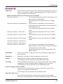
File tab
File Name ................. Specify the file name of the image that is to be scanned in.
File Type .................. In the pull-down menu, select the type of file to save.
Auto-Assign Filename
.................. The file name is automatically generated during scanning.
Direct Output to a File
.................. Image data is immediately stored in the file without displaying the image.
Save as 24-bit Color
.................. After the document is read, the data is automatically saved as 24-bit color
data.
Tip
The file name is automatically generated when a number is appended to the right end of the file
name that was saved using this setting. The automatically generated file name is the same as
the previous file name except that the appended number is incremented by 1.
The number is incremented until the maximum limit is reached, and then reverts to zeroes.
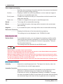
Options tab
Scan Speed ............. To scan a soft (limp) document or reduce the load on the document,
select Low. (Usually set to Standard).
Batch Scan .............. If you enable this option, document scanning will operate continuously,
thereby saving time. The documents submitted to batch scanning must
be uniform in image quality so that it will not be necessary to adjust the
scanning settings for each document.
Tip
When you enable Batch Scan, enable Auto-Assign Filename in the File tab. Neither Continuous
Scan nor Manual Loading is available.
Scanning Master 21+
3-17
3. OPERATIONS
Continuous Scan .... If you enable this parameter, document scanning will operate continuously without closing the Scan window.
Tip
When you enable Continuous Scan, enable Auto-Assign Filename in the File tab. Batch Scan is
not available.
Detecting the Front Edge of Document
.................. If this parameter is enabled, the leading edge of the document is detected. If the detection operation is performed each time a document is
scanned, the overall scanning efficiency is decreased but the leading
edge of the document will be detected correctly.
If this parameter is disabled, the leading edge of the document is not
detected. Eliminating the detection operation increases the overall scanning efficiency, but there may be a certain amount of blank space created
at the leading edge of the data. Moreover, if a document that is longer
than the specified Paper Size is scanned, the data will be scanned in at
the longer length.
This setting cannot be specified for the CS300/400 models.
Checkpoint
This function is effective when the Batch Scan function is enabled.
If batch scanning is performed when this function is disabled, the automatic detection function
specified for Paper Size may not operate correctly if the document is not inserted correctly.
Furthermore, paper jams may occur more frequently. We recommend that this function always
be enabled.
When scanners are IS200 and CS500/600 models, this function can be enabled or disabled if
the firmware version is 1.70 or later. With earlier firmware versions, it is always enabled.
Manual Loading ...... Enable this parameter if you want to scan in thin or large documents.
If you enable this parameter, documents will not be fed automatically. If
you disable it, documents will be fed automatically.
This setting cannot be specified for the SK200 model.
Delay Time .............. Required if document feed is initiated automatically. Set the delay time
from when the document touches the sensor switch of the scanner to
when the feed is actually initiated. (In 0.1-s increments). If, for example,
you set “15” for the delay time, feed is initiated 1.5 seconds after the
document touches the sensor switch.
Auto Eject ................ This section lets you control how the document is to be moved after being
scanned.
None .................... The document is not ejected and stops at the position where scanning ends.
Eject to Back ....... The document is ejected to the back of the scanner.
Front .................... The document is fed to the front of the scanner.
3-18
Scanning Master 21+
3. OPERATIONS
Back .................... The document is fed to the back of the scanner.
Only the None and Eject to Back settings can be specified for the SK200
model.
Scanning Master 21+
3-19
3. OPERATIONS
3.4
Scan and Print
Select the Scan and Print command from the Scan menu, or click the Scan and Print button in
the Scan Tools sub-window, or click the Scan and Print button on the toolbar to output
scanned data to a preset printer after scanning is completed.
Tip
If you want to save the printed image to a file, click "Direct Output to File" on the File tab before
scanning the document.
Click the printer tab to enter or modify printer settings, including printer selection.
Scan tab
Printer ...................... Select the printer to which you want to output scanned data.
Properties button .... Shows the properties of the selected printer. For more information on
printer setup, refer to the instruction manual provided with your printer.
Paper Size ............... Specify the size of paper on which to output the scanned data.
Scale ........................ Specify a scale between 25% and 400%.
Adjust to Paper Size
.................. The scale is automatically set to match the paper size in which the
scanned data is output.
Number of Copies ... Specify the number of copies you want to output. You can specify a value
from 1 to 999.
Center of Paper ....... The scanned data is output so that the center of the data coincides with
the center of the printer print area.
Left Margin .............. The scanned data is offset by the specified amount from the left margin of
the paper selected for output.
Top Margin .............. The scanned data is offset by the specified amount from the top of the
paper selected for output.
3-20
Scanning Master 21+
3. OPERATIONS
3.5
Scanner Adjustment
You should set the adjustment features if you want to approximate the accuracy of the scannedin drawing to that of the original. (Fine-tuning the accuracy, depending on the quality of the
document.)
Usually this adjustment is unnecessary.
You can adjust the scanner (Distance Correction, Joint Fine-adjustment, and Trapezoidal
Correction) by selecting the Tools menu > Adjust Scanner.
The settings that can be specified vary according to the scanner model.
Distance Correction
Corrects distances as appropriate for the type of document.
The setting may be within approximately ±1%. It is effective until the scanner is powered off.
To use the Distance Correction function, you must first measure a vertical line drawn on the
document using the following procedure:
(1) Select a document that contains one or more drawn vertical lines. Scan it in at 600 dpi in
portrait orientation.
(2) Measure the length of the vertical line on the document. Define it as x (Distance Measured
on Document).
(3) Using the View menu > Relative Measure > Distance between Specified Points, measure the length of the corresponding vertical line in the image data. Define it as y (Distance
Measured after Scanning).
(4) In the Scanner Adjustments window, click the Distance Correction button in Adjustments. The Distance Correction window appears.
(5) Type in the Distance Measured on Document x and Distance Measured after Scanning
y values. These values must be within the range of distance correction.
(6) Click the OK button to calculate the corrections. Distance correction will take effect from the
next document scanned.
Scanning Master 21+
3-21
3. OPERATIONS
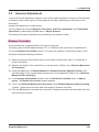
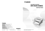
Joint Fine-adjustment
Graphtec scanners use multiple rows of sensors.
In rare cases, there may be one or two overlapping or missing pixels in the data at a joint
between the rows of sensors.
Overlapped data
Original Document
Data overlaps
Missing data
Original Document
Data is missing
In either of these cases, finely adjust the sensor-to-sensor joints using the following procedure:
(1) In the Scanner Adjustments window, click the Joint Fine-adjustment button in Adjustments to open the Joint Adjustment window.
(2) Finely adjust each of the joints.
For overlapping pixels in the data at a joint, set a negative value. For missing pixels, set a
positive value.
Usually set 0 (0 is the factory default) for the joints.
(3) Once you have completed the settings, click the OK button.
3-22
Scanning Master 21+
3. OPERATIONS
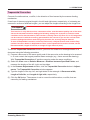
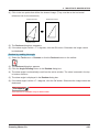
Trapezoidal Correction
Corrects fine deformations, or shifts, in the direction of feed caused by the scanner feeding
mechanism.
If two lines of the same original length in the left and right areas, respectively, of a drawing are
scanned in as lines of different lengths, you can adjust the lengths according to the longer line.
Checkpoint
This function is only effective when a document of the same document quality and of the same
size as the document used for making the following settings are scanned in under the same
conditions as for that document. (This function is usually set to off.) Even if it is off, image data
can be scanned in with the accuracy guaranteed for the scanner. If you use the scanner after
incorrect settings have been made using this function, the accuracy may be lowered.
To turn off Trapezoidal correction, select the Tools menu > Adjust Scanner and click the Trapezoidal Correction button in Adjustments. Then, in the Trapezoidal Correction window, set the
Document width, Length of left side, or Length of right side to 0 (zero).
To use the Trapezoidal Correction function, you must first measure a rectangle drawn on a
document using the following procedure:
(1) Prepare a document of the same quality and of the same size as the drawing to be scanned
in. It must contain the largest possible drawn rectangle (e.g., frame around the drawing).
With Trapezoidal Correction off, perform scanning under the same conditions.
(2) Select the View menu > Relative Measure > Distance between Specified Points, and
measure the lengths of the left, right, and top sides.
(3) In the Scanner Adjustments window, click the Trapezoidal Correction button in Adjustments. The Trapezoidal Correction window appears.
(4) Type the lengths of the top, left, and right sides of the rectangle in Document width,
Length of left side, and Length of right side, respectively.
(5) Click the OK button. The scanner is set to correct the deformations, or shifts, that are
caused by its feeding mechanism.
Scanning Master 21+
3-23
4. IMAGE DATA MANIPULATION
4.
IMAGE DATA MANIPULATION
This chapter describes how to display and manipulate image data and perform the basic edit
functions using Scanning Master 21+.
This chapter consists of the following sections:
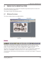
4.1
Window Overview
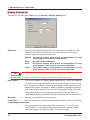
The various window functions are explained below.
Toolbar
View window
Status Bar
Toolbar
The toolbar is located above the application window and just under the menu bar. On the
toolbar, you can operate many tools used in Scanning Master 21+ by clicking them with the
mouse. To show or hide the toolbar, select the View menu > Toolbar command.
The above view of the toolbar shows the initial settings. It can be customized by selecting the
Tools menu > Customize command (see Section 4.6, "Other Image Edit Functions").
For descriptions of the functions of the other buttons on the toolbar, see Chapter 5, “Description
of Functions”.
Scanning Master 21+
4-1
4. IMAGE DATA MANIPULATION
Scan Tools
The Scan Tools are normally displayed in the upper part of the application window, immediately
below the toolbar.
To show or hide the Scan Tools, select the View menu > Scan Tools command.
For information on using Scan button, refer to Chapter 3.2, Scanning Procedure.
For information on using Scan and Print button, refer to Chapter 3.4, Scan and Print.
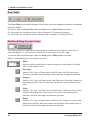
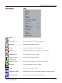
Edit Bar (Editing Function Tools)
The Editing tools are located above the application window and just under the menu bar. In
Scanning Master 21+, click the icon of the tool you want to use to edit the image.
To show or hide the Editing tools, select the View menu > Editing Tool command.
Below is a brief description of the button functions:
Width
Sets the width (in pixels) that is used for erasure or modification in the Edit
menu or that used for lines.
Rectangle
Used for Cut, Copy, or Erase Area in the Edit menu. Left-click two points.
The area is defined by the rectangle containing them as opposite vertexes.
Polygon
Used for Cut, Copy, and Erase Area in the Edit menu. Define the vertexes of
the polygon by left-clicking. Double-click on the last vertex to determine the
area.
Circle
Used for Cut, Copy, or Erase Area in the Edit menu. Define the center of the
circle by left-clicking. Move the mouse until a circle of the desired size is
obtained. Left-click there again to determine the area.
Ellipse
Used for Cut, Copy, or Erase Area in the Edit menu. Define the center of the
ellipse by left-clicking. Move the mouse until an ellipse of the desired size is
obtained. Left-click there again to determine the area.
4-2
Scanning Master 21+
4. IMAGE DATA MANIPULATION
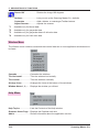
Status Bar
The Status Bar is shown at the bottom of the Scanning Master 21+ window.
When you select a menu command or a button on the toolbar, the Status Bar displays a brief
description of the command, the cursor position, and the magnification of the image data displayed.
To show or hide the Status Bar, select the View menu > StatusBar command.
Scanning Master 21+
4-3
4. IMAGE DATA MANIPULATION
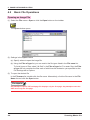
4.2
Basic File Operations
Opening an Image File
(1) Select the File menu > Open or click the Open button on the toolbar.
The Open window opens.
(2) Settings in the Open window
(a) Specify where to open the image file.
(b) Using the Files of type list, you can restrict the file types listed in the File name list.
To list all types of files, select "all files" in the Files of type list. For raster files, the Files
of type list only contains the files each of which has the extension you specified on the
File Settings tab in Options.
(3) To open the desired file
In the File name list, double-click the file name. Alternatively, click the file name in the File
Name list and click the Open button.
Checkpoint
Any attempt to open a TIFF multipage file displays only the first page. Any attempt to save the
data saves only the first page.
4-4
Scanning Master 21+
4. IMAGE DATA MANIPULATION
Saving an Image File
(1) Select the window in which the image you want to save is on-screen.
(2) Select the File menu > Save or click the Save button on the toolbar.
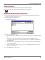
Changing the File Name, Folder, or File Format
(1) If you want to change the folder, file name, or file format before saving the file, select the
window in which the image is on-screen.
(2) Select the File menu > Save As.
The Save As window opens.
(3) Settings in the Save As window
(a) To save the image in a different file format, select the new format from the Save as type
list.
The extension of the new file format will change to the default character string.
The default extension for the file format can be specified on the Tools menu > Options >
File Settings tab.
(b) To save the image under a different file name, type the new name in the File name box.
The file will be renamed.
(c) To save the image in a different folder or drive, set the folder and drive in the location
where you want to save it.
(4) Click the Save button to save the file.
Scanning Master 21+
4-5
4. IMAGE DATA MANIPULATION
4.3
Printing Image Data
(1) Open the window that contains the preview of the image to be printed.
(2) Select the File menu > Print or click the Print button on the toolbar.
The Print window opens. Complete all the settings, and click the OK button to initiate printing.
Tip
After selecting the File menu > Page Setup, you can set the document size, the print orientation, and the magnification.
You should turn on Direct Output to Plotter in the Page Setup dialog box, for example, if you
want to output a long-length image on a Graphtec plotter or similar output equipment. Usually
leave this check box off.
4-6
Scanning Master 21+
4. IMAGE DATA MANIPULATION
4.4
Viewing the Image
Scrolling the Image
If the image is scrollable, a scroll bar appears at both the right end and bottom. The scroll box in
each scroll bar indicates the current position in the on-screen image. Using the mouse, you can
scroll the image to move to the desired position in a hidden area.
Perform one of the following:
◆ Drag the horizontal or vertical scroll box.
◆ Click the scroll arrow at either end of a scroll bar.
◆ Click the scroll bar.
◆ Press the <←>, <→>, <↑>, or <↓> key on the keyboard.
Previewing the Whole Image
This function scales the on-screen image so that the whole image fits in the current window
size.
Perform one of the following:
◆ Select the View menu > Fit.
◆ On the toolbar, click the Fit button.
◆ Press the <F2> key on the keyboard.
Viewing the Image at Pixel Level
This function displays the image at pixel level, associating one dot with one pixel on the screen.
All the data can be displayed precisely.
Perform one of the following:
◆ Select the View menu > 1:1.
◆ On the toolbar, click the 1:1 button.
◆ Press the <Ctrl>+<1> keys on the keyboard.
Scanning Master 21+
4-7
4. IMAGE DATA MANIPULATION
Zooming in on the Image
This function zooms in on the on-screen image, by a factor of 2 or 4, relative to the one-to-one
view size.
◆ Select the View menu > Zoom In.
Tip
If you want to double the size of the image relative to the current one, click the Zoom In button
on the toolbar once.
Zooming out the Image
This function zooms out the on-screen image, by a factor of 1/2, 1/4, 1/8, or 1/16, relative to the
one-to-one view size.
◆ Select the View menu > Zoom Out.
Tip
If you want to zoom the image to half its current size, click the Zoom Out button on the toolbar
once.
4-8
Scanning Master 21+
4. IMAGE DATA MANIPULATION
Bird's Eye Display
You can show or hide the Bird's Eye that is used to manipulate the on-screen image (for example, zooming in on the image).
◆ Select the View menu > Bird's Eye.
◆ On the toolbar, click the Bird's Eye button.
◆ Press the <F6> key on the keyboard.
Tip
You can show the Bird's Eye button by customizing the toolbar.
How to use the Bird's Eye Function
The Bird's Eye shows the overview of the on-screen image and what section of the overview is
currently displayed in the View window.
In addition, you can control display of the View window through the Bird’s Eye.
(1) Moving the display position
With the left mouse button, drag the view range in the overview to the desired position to display.
(2) Setting the display position and the magnification
With the right mouse button, drag the overview. Once the desired range to display in the View
window is obtained, release the button. To cancel setting of the view range, press the <Esc>
key during drag.
Scanning Master 21+
4-9
4. IMAGE DATA MANIPULATION
Zoom Display
You can show or hide the Zoom function that is used to zoom the area located at the current
cursor position.
◆ Select the View menu > Zoom.
◆ On the toolbar, click the Zoom button.
◆ Press the <F11> key on the keyboard.
Tip
You can show the Zoom button by customizing the toolbar.
How to use Zoom
Zoom displays the detailed view of a zoomed section in the area containing the current cursor
position.
Setting the magnification
Left-click Zoom to make it active. Next, use the <+> key to zoom in on the view or the <-> key
to zoom it out. For the magnification, you can select 1/16, 1/8, 1/4, 1/2, 1, 2, 4, or 8.
Loupe Display
You can turn on or off the Loupe Mode, which enables you to zoom in on the area around the
cursor.
◆ Select the View menu > Loupe.
◆ On the toolbar, click the Loupe button.
◆ Select the <F12> key on the keyboard.
Tip
You can show the Loupe button by customizing the toolbar.
How to use Loupe
If Loupe Mode is on, the view is zoomed in on while you are holding down the left mouse
button in the View window. You can change the size and magnification for Loupe by using
Display Settings in the Tools menu > Options. In addition, you can change the magnification
by pressing the <+> or <-> key while the image is currently zoomed in on.
4-10
Scanning Master 21+
4. IMAGE DATA MANIPULATION
Image Info
You can display the window that lists detailed information about the on-screen image.
◆ Select the View menu > Image Info.
◆ On the toolbar, click the Image Info button.
Tip
You can show the Image Info button by customizing the toolbar.
Scanning Master 21+
4-11
4. IMAGE DATA MANIPULATION
4.5
Using the Edit Functions
You can edit image data easily using the function buttons on the toolbar.
Tip
While you are editing image data, the cursor may change as appropriate for the actions of each
command or function. While the cursor is in the form of a cross, the point indicated by the
cursor is its intersection.
Cut
The data you selected from the on-screen image is cut and saved in memory. Once it is cut, the
existing memory contents are replaced by the new cut data.
To cut a specific area from the image, take the following steps:
(1) Select the Edit menu > Cut, or click the Cut button on the toolbar.
(2) Next use the Cut tool as follows. Press the <Esc> key to cancel the operation.
(a) For a rectangle, define any two points by left-clicking. The contents are deleted from
the rectangular area that contains these points as opposite vertexes, and saved in
memory.
(b) For a polygon, define the positions of the vertexes of the polygon by left-clicking (every
polygon is a closed form). With the left button, double-click the last vertex of the area
you want to cut. The contents of the defined area are deleted and saved in memory.
(c) For a circle or ellipse, take the following steps: Left-click the center of the area you
want to cut. To define the cut area, move the mouse until a circle or ellipse of the desired size is obtained. Click with the left button again. At this time, the contents of the
defined area are deleted and saved in memory.
(3) To terminate use of the Cut tool
Select Edit > Cut again, or click the Cut button on the toolbar again.
Tip
You can select the Cut tool shape (rectangle, polygon, circle, or ellipse) from the Edit Function
Tools on the Edit Bar.
Checkpoint
This function is available only for bilevel data.
4-12
Scanning Master 21+
4. IMAGE DATA MANIPULATION
Copy
The data you selected from the on-screen image is copied and saved in memory. Once it is
copied, the existing memory contents are replaced by the new copied data.
To copy a specific area from the image, take the following steps:
(1) Select the Edit menu > Copy, or click the Copy button on the toolbar.
(2) Next use the Copy tool as follows. Press the <Esc> key to cancel the operation.
(a) For a rectangle, define any two points by left-clicking. The contents of the rectangular
area that contains these points as opposite vertexes are saved in memory.
(b) For a polygon, define the positions of the vertexes of the polygon by left-clicking (every
polygon is a closed form). With the left button, double-click the last vertex of the copy
area. The contents of the defined area are saved in memory.
(c) For a circle or ellipse, take the following steps: Left-click the center of the copy area.
To define the copy area, move the mouse until a circle or ellipse of the desired size is
obtained. Click with the left button again. At this time, the contents of the defined area
are saved in memory.
(3) To terminate use of the Copy tool
Select Edit > Copy again, or click the Copy button on the toolbar again.
Tip
You can select the Copy tool shape (rectangle, polygon, circle, or ellipse) from the Edit Function Tools on the Edit Bar.
Checkpoint
This function is available only for bilevel data.
Scanning Master 21+
4-13
4. IMAGE DATA MANIPULATION
Paste
This function pastes the memory contents to the on-screen image. If the memory contains no
data, this command is not available. Scanning Master 21+ allows you to use one of three paste
functions, depending on the circumstances.
New Image
An on-screen View window is created with the memory contents as the new image data.
The procedure is as follows.
(1) Select the Edit menu > Paste > New Image, or click the New Image button on the toolbar.
(2) A new View window is created.
Current Window
The memory contents are pasted to the cursor position.
The procedure is as follows.
(1) If you want to paste the area to a window other than the one where you performed Cut or
Paste, open the window to which you want to paste the area.
(2) Select the Edit menu > Paste > Current Window, or click the Paste to Current Window
button on the toolbar.
(3) By pressing and holding down the left mouse button, you can view the image contained in
the memory or in that area. Press the Esc key to terminate the operation.
(4) While holding down the left mouse button, drag the mouse to the desired position.
(5) Release the mouse button to paste the contents to the image.
(6) To terminate use of the Paste tool
Select Edit > Paste > Current Window again, or click the Paste to Current Window
button on the toolbar again
Transparent Background
The memory contents are pasted to the cursor position. Unlike the Current Window command,
these contents are pasted in with the background in transparent color.
To paste the cut or copied area to the image, take the following steps:
(1) If you want to paste the area to a window other than the one where you performed Cut or
Paste, open the window to which you want to paste the area.
(2) Select the Edit menu > Paste > Transparent Background or click the Transparent Background button on the toolbar.
4-14
Scanning Master 21+
4. IMAGE DATA MANIPULATION
(3) By pressing and holding down the left mouse button, you can view the image contained in
memory or in that area. Press the Esc key to terminate the operation.
(4) While holding down the left mouse button, drag the mouse to the desired position.
(5) Release the mouse button to paste the memory contents to the image.
(6) To terminate use of the Paste tool
Select Edit > Paste > Transparent Background again, or click the Transparent Background button on the toolbar again
Checkpoint
This function is available only for bilevel data.
Rubout
The image is erased in a manner similar to rubbing out with an eraser on the document (partial
erasure).
The procedure is as follows.
(1) Select the Edit menu > Rubout or click the Rubout button on the toolbar.
(2) Press and hold down the left mouse button to drag the Rubout tool and erase the image.
(3) To terminate use of the Rubout tool
Select Edit > Rubout again, or click the Rubout tool on the toolbar again.
Tip
You can set the width of the Rubout tool using the Editing Function Tools on the Edit Bar.
Checkpoint
This function is only available for bilevel data.
Scanning Master 21+
4-15
4. IMAGE DATA MANIPULATION
Erase Area
The specified area in the on-screen image is erased.
The procedure is as follows.
(1) Select the Edit menu >Erase Area or click the Erase Area button on the toolbar.
(2) Next use the Erase Area Tool as follows. Press the Esc key to terminate the operation.
(a) For a rectangle, left-click the two points where opposite vertexes of the rectangular
area you want to erase are located.
(b) For a polygon, define the positions of the vertexes of the polygon by left-clicking (every
polygon is a closed form). With the left mouse button, double-click the last vertex of the
area you want to erase.
(c) For a circle or ellipse, take the following steps: Left-click the center of the area you
want to erase. Move the mouse until a circle or ellipse of the desired size is obtained.
Click with the left button again in the area you want to erase.
(3) To terminate use of the Erase Area tool
Select Edit > Erase Area again, or click the Erase Area tool on the toolbar again.
Tip
You can select the Erase Area tool shape (rectangle, polygon, circle, or ellipse) from the Editing
Function Tools on the Edit Bar.
Checkpoint
This function is available only for bilevel data.
4-16
Scanning Master 21+
4. IMAGE DATA MANIPULATION
Revise
You can retouch the on-screen image in a manner similar to using a pencil on the document.
The procedure is as follows.
(1) Select the Edit menu >Revise or click the Revise button on the toolbar.
(2) Press and hold down the left mouse button to drag the Revise Tool and retouch the image.
(3) To terminate use of the Revise tool
Select Edit > Revise again, or click the Revise tool on the toolbar again.
Tip
You can set the Revise tool width using the Editing Function Tools.
Checkpoint
This function is available only for bilevel data.
Line
You can draw a line on the on-screen image.
The procedure is as follows.
(1) Select the Edit menu >Line or click the Line button on the toolbar.
(2) Define the start position of the line by left-clicking there. Next move to the desired position,
and left-click there again to define it as the end position. While holding down the <Shift>
key, enter the second position to obtain a horizontal, vertical, or 45-degree line.
(3) To terminate use of the Line tool
Select Edit > Line again, or click the Line tool on the toolbar again.
Tip
You can set the Line tool width using the Editing Function Tools.
Checkpoint
This function is available only for bilevel data.
Scanning Master 21+
4-17
4. IMAGE DATA MANIPULATION
Undo Edit Function
This function lets you undo the immediately previous action.
The procedure is as follows.
◆ Select the Edit menu > Undo.
◆ On the toolbar, click the Undo button.
Tip
If you have saved the image or used a tool, this function cannot be used.
You can show the Undo button by customizing the toolbar.
Checkpoint
This function is available only for bilevel data.
Redo Undo Edit
This function restores the last edit you did using Undo.
The procedure is as follows.
◆ Select the Edit menu > Redo.
◆ On the toolbar, click the Redo button.
Tip
You can show the Undo button by customizing the toolbar.
Checkpoint
This function is available only for bilevel data.
4-18
Scanning Master 21+
4. IMAGE DATA MANIPULATION
4.6
Other Image Editing Functions
Various editing functions can be used from the Tools menu.
Tip
The Crop and Skew correction buttons can be displayed by customizing the toolbar.
Preview display
The following explanations are common to the Bilevel and Modify Color preview displays.
Fit button
Enlarges or reduces the image to display the entire image within the current
window size.
1:1 button
Displays the image at one dot per pixel.
Zoom In button
Displays the image at twice its current size.
Zoom Out button
Displays the image at half its current size.
Update Image button
Refreshes the image to the current settings after making the specified
changes.
Scanning Master 21+
4-19
4. IMAGE DATA MANIPULATION
Tip
To display a range on the image, right-click and drag to create a rectangular area. When the
mouse button is released, the image in the range specified will be displayed in the current
window.
To scroll the image, left-click and drag the Original Image box or Modified Image box with the
mouse. The image scrolls in the direction in which the mouse is moved until the mouse button
is released.
Despeckling
Any remaining speckles are removed from the background of the on-screen image.
The procedure is as follows.
(1) Select the Tools menu > Despeckle, or click the Despeckle button on the toolbar.
(2) The Despeckle dialog box appears.
(3) Set the speckle size in the Despeckle dialog box, then click the OK button.
Checkpoint
This function is available only for bilevel data.
Deskew
When the scanner has scanned in a skewed document, the skewed on-screen image can be
corrected.
Deskew by setting the angle
(1) Select the Tools menu > Deskew or click the Deskew button on the toolbar.
(2) The Deskew dialog box appears.
(3) Type the new angle in the Deskew dialog box, then click the OK button.
Deskew by line
(1) Select the Tools menu > Deskew or click the Deskew button on the toolbar.
(2) The Deskew dialog box appears.
(3) Click the Set Angle button in the Deskew dialog box.
4-20
Scanning Master 21+
4. IMAGE DATA MANIPULATION
(4) Click in the two points that define the skewed image. (They must be on the horizontal
reference line for the document.)
Skewed document
Deskewed document
2 points to click
(5) The Deskew dialog box reappears.
(6) If the skew angle is within ±7.1 degrees, click the OK button. Otherwise the image cannot
be deskewed.
Deskew by reading the angle
(1) Select the Tools menu > Deskew or click the Deskew button on the toolbar.
(2) The Deskew dialog box appears.
(3) Click the Angle Reading button in the Deskew dialog box.
(4) The skew angle is automatically read from the active window. The skew is sensed in the top
to bottom direction.
(5) The skew angle is displayed in the Deskew dialog box.
(6) If the skew angle is within ±7.1 degrees, click the OK button. Otherwise the image cannot be
deskewed.
Checkpoint
This function is available only for bilevel data.
Scanning Master 21+
4-21
4. IMAGE DATA MANIPULATION
Crop
You can easily crop any sections protruding from the defined rectangular area.
A0-Landscape to B4-Portrait
This function crops any sections outside the frame defining the specified document size.
The procedure is as follows.
(1) Select the Tools menu > Crop > ISO A0-Landscape to DIN A4-Portrait, or click the ISO
A0-Landscape to DIN A4-Portrait button on the toolbar.
(2) The frame defining the document size you selected appears. This is the range for clipping
the image inside the frame.
(3) Move the mouse to define the area to be clipped, and then left-click to delete the sections
outside the frame.
User 1 to 4
This function crops any sections outside the frame outside the registered document size.
The procedure is as follows.
(1) Select the Tools menu > Crop > User 1 to 4, or click the User 1 to 4 button on the toolbar.
(2) The dialog box for defining the size of the frame for clipping appears.
(3) Input the width and height for the document size, and then click the OK button.
(4) Move the mouse to define the area to be clipped, and then left-click to delete the sections
outside the frame.
Set Region
This function crops any sections outside the user-specified region.
The procedure is as follows.
(1) Select the Tools menu > Crop > Set Region, or click the Set Region button on the toolbar.
(2) Left-click at the desired position to define the start position.
(3) Move the mouse to define the area to be clipped, and then left-click once again to delete the
sections outside the frame.
4-22
Scanning Master 21+
4. IMAGE DATA MANIPULATION
Move
Use this function to move the on-screen image to a different position without resizing it.
The procedure is as follows.
(1) Select the Tools menu > Crop > Move, or click the Crop at Current Size button on the
toolbar.
(2) The frame defining the current size appears. This is the range for clipping the image inside
the frame.
(3) Move the mouse to define the area to be clipped, and then left-click to delete the sections
outside the frame.
Tip
The Crop reference point can be changed within the General tab in Options in the Tools menu.
Similarly, the home point can be changed in the sequence “Center” → “Upper Left” → “Lower
Left” → “Lower Right” → “Upper Right” → “Center” by pressing the Home key while selected.
If you want to scroll the area during setting, use the [←], [→], [↑], [↓] keys on the keyboard.
Pressing the <ESC> key cancels the settings.
Resize
You can resize the on-screen image.
The procedure is as follows.
Specifying Pixel
(1) Select the Tools menu > Resize, or click the Resize button on the toolbar.
(2) The Resize dialog box is displayed.
(3) Select Pixel as the Specification Method.
(4) Specify the New Width and New Height as pixel units, and then click the OK button.
Specifying Paper Size
(1) Select the Tools menu > Resize, or click the Resize button on the toolbar.
(2) The Resize dialog box is displayed.
(3) Select Paper Size as the Specification Method.
(4) Select the new paper size from the options in Paper Size, and then click the OK button.
Tip
If you select User Size, you can specify the New Width and New Height.
Scanning Master 21+
4-23
4. IMAGE DATA MANIPULATION
Specifying Resolution
(1) Select the Tools menu > Resize, or click the Resize button on the toolbar.
(2) The Resize dialog box is displayed.
(3) Select Resolution as the Specification Method.
(4) Specify a new resolution for either the New Width or the New Height (both settings will be
the same), and then click the OK button.
Checkpoint
In this case, Fix the Aspect Ratio will be enabled.
Specifying Scale
(1) Select the Tools menu > Resize, or click the Resize button on the toolbar.
(2) The Resize dialog box is displayed.
(3) Select Scale as the Specification Method.
(4) Specify a Scale value for New Width and New Height, and then click the OK button.
Checkpoint
This function is available only for bilevel data.
Smoothing
Smoothes out grayscale images by averaging each pixel value with those of the surrounding pixels.
The procedure is as follows.
(1) Select the Tools menu > Smoothing, or click the Smoothing button on the toolbar.
(2) Smoothing is performed
Checkpoint
This function is available only for grayscale data.
4-24
Scanning Master 21+
4. IMAGE DATA MANIPULATION
Reduce Colors to Bilevel
Changes grayscale or color images to bilevel images.
The procedure is as follows.
(1) Select the Tools menu > Bilevel, or click the Bilevel button on the toolbar.
(2) The Bilevel dialog box is displayed.
(3) Select the Color Depth Reduction Method
Auto ......................... Calculates the most suitable threshold value for each area while
converting the data to bilevel format.
Manual ..................... Converts the data to bilevel format at one threshold value for the
entire area.
Dither ....................... Sets conversion to bilevel using a dither pattern.
Error Diffusion ........ Sets conversion to bilevel using an error diffusion method.
(4) Adjust the Threshold and Variability parameters according to the Color Depth Reduction
Method selected.
Threshold ................ Sets the threshold value for manual bilevel conversion.
Variability ................ Specifies whether to convert to black or white for automatic bilevel
conversion. To make the image blacker, reduce the value, and to
make the image whiter, raise the value.
(5) Click the Update Image button to display the updated image.
(6) Repeat steps (3) to (5) until the desired image is obtained.
(7) Click the OK button to close the dialog box.
Tip
Please refer to the Preview Display on page 4-19 for details on the Original Image and Modified
Image windows.
Checkpoint
This function can only be used for grayscale and color data.
Scanning Master 21+
4-25
4. IMAGE DATA MANIPULATION
Modify Color
Modifies a specified color on the image.
The procedure is as follows.
(1) Select the Tools menu > Modify Color, or click the Modify Color button on the toolbar.
(2) The Modify Color dialog box is displayed.
(3) Click the New Color button
, then click on the color to be modified in the Original Image
box. New colors can also be added from the palette by pressing the Select from Palette
button
.
To change colors enclosed in a specified region into a single color, left-click and drag the
pointer in the Original Image box to create a region enclosing the colors to be modified.
After the mouse button released, the color enclosed in the region will be added to the
Original Color list. Up to 16 colors can be added to the list at once.
(4) To add a color to be modified, increase the allowable range or click the Add button
and
click on the colors to be added in the Original Image box. To add colors enclosed in a
specified region, left-click and drag the pointer in the Original Image box to create a region
enclosing the colors to be added. After the mouse button is released, the colors enclosed in
the region will be added to the list. Up to 16 colors can be added to the list at once.
(5) To modify a selected color, double-click on the color to be modified to display the Select
Color window, then modify the color.
(6) To delete a color from the list, select the color on the list and click the Delete button
(7) Click the Update Image button
.
. The Modified Image box will be updated.
(8) Repeat steps 3 to 7 until the desired image is obtained.
(9) Click the OK button to close the window. At this time, if Display in New Window has been
selected, a new window is created separately and displayed.
Allowable Range ..... Specifies the allowable range for the color to be modified.
If the Allowable Range setting is 0, only the colors specified in Original
Color are changed to the colors set in Modified Color.
If the Allowable Range setting is 20, the colors specified in Original
Color are changed to the colors set in Modified Color which fall into the
± 20 range of that color's respective RGB values.
If the Allowable Range setting is 255, all colors are changed to the colors
set in Modified Color.
Apply to All Colors .. Specifying this option applies Allowable Range changes to all the colors
displayed in the Original Color list.
Modify Other Colors
.................. If this option is specified, colors which have not been selected are all
changed to the same color. If you click on an area where a color is
displayed, the Select Color Window is displayed for setting the modified
colors.
4-26
Scanning Master 21+
4. IMAGE DATA MANIPULATION
Display in New Window
.................. If this option specified, displays the modified image in a new window.
Load Button ............ Loads the settings from an already existing file. The Load dialog box is
displayed for you to select the file to be loaded to the window.
Save Button ............. Saves the current settings to a file. The Save dialog box is displayed for
you to specify a suitable file name for saving.
At this time, if you save to the Color folder inside the folder in which
Scanning Master Copy Color is installed, the settings can be specified
when scanning in data from the scanner.
Tip
Please refer to the Preview Display on page 4-19 for details on the Original Image and Modified
Image windows.
Checkpoint
This command can only be used for color data.
Select Color window
Clicking the Select from Palette button in the Modify Color dialog box displays the Select
Color window.
The procedure is as follows.
(1) Click on the color to be selected. Multiple colors can be selected by pressing the <Shift> or
<Ctrl> keys while clicking.
(2) Click the OK button to close the window.
Tip
Display Order changes the color display order. Colors can be displayed in order of index,
brightness, or hue.
Undo
This function undoes the previous raster action, such as despeckling, deskewing, cropping, or
resizing. This operates only once for each action.
Perform one of the following.
◆ Select the Tools menu > Undo.
◆ Click the Undo button on the toolbar.
Scanning Master 21+
4-27
4. IMAGE DATA MANIPULATION
Making the Image Negative
This function inverts the colors of the on-screen image.
Perform one of the following:
◆ Select the Tools menu > Negative.
◆ On the toolbar, click the Negative button.
◆ Press the <F8> key on the keyboard.
Mirroring the Image
This function mirrors the image on the vertical axis.
Perform one of the following:
◆ Select the Tools menu > Mirror.
◆ On the toolbar, click the Mirror button.
Rotating the Image
This function rotates the on-screen image 90 degrees clockwise or counterclockwise, or 180 degrees.
Perform one of the following:
Rotating the image 90 degrees counterclockwise
◆ Select the Tools menu > Rotate 90°° CCW.
◆ On the toolbar, click the Rotate 90°° CCW button.
◆ Press the <F9> key on the keyboard.
Rotating the image 90 degrees clockwise
◆ Select the Tools menu > Rotate 90°° CW.
◆ On the toolbar, click the Rotate 90°° CW button.
◆ Press the <F10> key on the keyboard.
Rotating the image 180 degrees
◆ Select the Tools menu > Rotate 180°° .
◆ On the toolbar, click the Rotate 180°° button.
4-28
Scanning Master 21+
4. IMAGE DATA MANIPULATION
4.7
Image Measurement
This function measures a point-to-point distance based on the current resolution.
If the reference unit length is known, relative measurement is enabled based on this length.
Setting the Unit Length
Set a new interval between the two points that are used for the reference.
The procedure is as follows.
(1) Select the View menu > Relative Measure > Unit Length.
(2) Click the two new points you want to use for the reference.
(3) The Measurement Reference dialog box appears.
(4) In the Measurement Reference dialog box, set the length of the designated interval.
(5) Click the OK button to close the dialog box.
Checkpoint
The scale you set in the Measurement Reference dialog box will take effect only for calculation
by the Distance between Specified Points command. It does not influence any other commands.
Measure the Distance Between Specified Points
Measure the relative distance between the two points.
The procedure is as follows.
(1) Select the View menu > Relative Measure > Distance between Specified Points.
(2) Click the two points for which you want to perform relative measurement.
(3) The Measured Results window appears.
Scanning Master 21+
4-29
5. DESCRIPTIONS OF FUNCTIONS
5.
DESCRIPTIONS OF FUNCTIONS
This chapter details the Options settings, the Scanning Master 21+ menus, and the file formats.
5.1
Options Settings
Perform the Scanning Master 21+ default operations. To set the Options, select the Tools menu
> Options.
File Settings tab
You can set options related to the on-screen image.
File Type .................. Select the type of the files the default extensions of which are to be
changed.
Extension ................ Set the extension you want to use by default for the selected file type.
Default Resolution .. Set the resolution that is used if no resolution has been written for the file
that is read through Open in the File menu.
JPEG Image Quality
.................. Specifies the image quality when a file is saved in JPEG format. A low
image quality reduces the size of the file, but renders a coarser image.
Scanning Master 21+
5-1
5. DESCRIPTIONS OF FUNCTIONS
Display Settings tab
This tab lets you select the Tools menu > Options > Display Settings tab.
Emphasis ................. Specify what pixels should be left when the image is zoomed out. This
option will take effect for the file you will open next time or for the onscreen image you will scan in next time.
Default : For bilevel images, black pixels are emphasized. For any
other images, no pixels are emphasized.
None : No pixels are emphasized.
Dark
: For bilevel images, black pixels are emphasized. For any
other images, pixels in dark color are emphasized.
Light : For bilevel images, white pixels are emphasized. For any
other images, pixels in light color are emphasized.
Tip
Setting "Dark" or "Light" for non-bilevel images of small size may have no effect.
High Speed .............. If you turn this option on, display-related operation (e.g., scroll) will speed up
for the file you will open next time or the on-screen image you scan in next
time through the scanner. (If the size of available memory space is small,
selecting this option may have no effect.) In addition, this option will cause
Edit Paste to show only the frame without dragging the image. Note that
reading from a file or scanning through the scanner may slow down, because data for display is created when the file is being opened or scanned in.
Maximize .................. Maximizes the default on-screen image.
Loupe Size ............... Set the loupe size in 1-pixel increments in the range from 50 to 500 pixels.
Loupe Magnification Rate
.................. Set the magnification of the loupe. You can select 1, 2, 4, or 8 for the
magnification. You can also change it by pressing the <+> or <-> key
while the image is currently zoomed in on with the Loupe.
5-2
Scanning Master 21+
5. DESCRIPTIONS OF FUNCTIONS
General tab
This tab lets you select the Tools menu > Options > General tab.
Recently Used File List
.................. Set the maximum number of the files listed at the bottom of the File
menu.
To enable the new setting, you must restart Scanning Master 21+.
Scan Conditions ..... Set the maximum number of the settings displayed in Save Conditions
and Load Conditions in the Scan menu.
Crop Outside Frame Reference Point
.................. Selects the position of the reference point when you specify Crop Outside
Frame.
Perform Interpolation for Image Correction
.................. If this option is specified, interpolation is performed to smooth out the
data when it is grayscale or color data, and deskew or trapezoidal correction has been performed.
Use Work File .......... If you turn this option on, you can save the scanned in on-screen image
temporarily in the work file, thereby reducing the memory area used.
Compress ................ If you turn this option on, the work file will be compressed. The disk area
will be reduced although operation may slow down a little.
Specify Folder ......... Turn this option on if you want to specify the folder in which the work file
will be created. If you turn it off, the work file will be created in the temporary folder of the system.
Browse button ........ When selecting the folder in which the work file will be created, you can
click this button to display the window that lets you select it.
Scanning Master 21+
5-3
5. DESCRIPTIONS OF FUNCTIONS
Unit Setup tab
This tab lets you select the Tools menu > Options > Unit Setup tab.
Unit ........................... Specifies the unit used for the Paper Size and other settings.
5-4
Scanning Master 21+
5. DESCRIPTIONS OF FUNCTIONS
5.2
Menus
File Menu
Open… ........................... Opens an existing on-screen image.
Close............................... Closes the currently open on-screen image.
Save ................................ Saves the latest version of the on-screen image file, with the
previous version overwritten.
Save As… ...................... Saves the on-screen image under a new name.
Print… ............................. Prints the on-screen image.
Page Setup… ................ Lets you set up the page layout and selection and connection
of the printer (or plotter).
File names 1, 2, 3, 4,… .. Opens a recently closed file.
Exit .................................. Exits Scanning Master 21+.
Scanning Master 21+
5-5
5. DESCRIPTIONS OF FUNCTIONS
Edit Menu
Undo ............................... Undoes the last action.
Redo ............................... Redoes the action you undid with Undo.
Cut .................................. Cuts and saves the selection in memory.
Copy ............................... Copies and saves the selection in memory.
Paste ............................... Pastes the memory contents to the on-screen image.
....... New Image
Creates an image window in which you view the data contained in memory as a new image.
....... Paste to Current Window
Pastes the data in memory to the cursor position.
....... Transparent Background
With the background in transparent color, pastes the data in
memory to the cursor position.
Rubout ............................ Rubs out part of the on-screen image with the background color.
Erase Area ...................... Paints the specified area in background color.
Revise ............................. Retouches the on-screen image in foreground color.
Line ................................. Draws a line in foreground color.
Tip
Pressing the <Esc> key during an Edit action cancels that action.
Checkpoint
The Edit menu is available only for bilevel data.
5-6
Scanning Master 21+
5. DESCRIPTIONS OF FUNCTIONS
View Menu
Fit .................................... Displays the whole on-screen image to fit it in the current
window area.
1:1 ................................... Displays the on-screen image as Normal size, with one dot
representing one pixel.
Zoom Out ....................... Zooms out the on-screen image.
Zoom In .......................... Zooms in on the on-screen image.
Bird's Eye ....................... Shows or hides the window containing the overview of the onscreen image.
Zoom............................... Displays the detailed view of the zoomed section of the area at
the current cursor position.
Loupe .............................. Turns on or off the Loupe Mode, which enables you to zoom in
on the area around the cursor.
Image Info... ................... Displays the window that lists detailed information about the
on-screen image.
Relative Measure ........... Measures a relative distance on the on-screen image.
Toolbar ........................... Shows or hides the toolbar.
StatusBar ....................... Shows or hides the Status Bar.
Editing Tools .................. Shows or hides the Editing Tools.
Scan Tools ..................... Shows or hides the Scan Tools.
Scanning Master 21+
5-7
5. DESCRIPTIONS OF FUNCTIONS
Tip
To view just one part of the image, define that area by pressing the right mouse button to
display a rectangle and dragging the mouse to the desired position. Once you release the
mouse button, the image in the defined area is viewed according to the current window.
To cancel setting of the defined area, press the <Esc> key during drag.
Scan Menu
Model Setup... .............. Displays the dialog box that lets you set the scanner
model for scanning.
Scan.............................. Displays the Scan window.
Scan and Print... .......... Displays the Scan window and automatically outputs
scanned data to the specified printer after scanning is
completed.
Save Conditions .......... Saves the current scanning settings.
Load Conditions .......... Loads the existing scanning settings.
5-8
Scanning Master 21+
5. DESCRIPTIONS OF FUNCTIONS
Tools Menu
Undo ............................... Undoes the previous raster action.
Despeckle…*1 ................ Removes speckles from the background.
Deskew… ....................... Deskews an on-screen image.
Crop ................................ Crops the outside of the defined area.
Resize…*1 ...................... Displays the dialog box that lets you resize data.
Smoothing*2 .................. Smooths the on-screen image.
Reduce Colors ............... Converts the image to bilevel.
to Bilevel*3
Modify Color*4 ............... Modifies a specified color within the image data.
Negative ......................... Color-inverts the on-screen image.
Mirror .............................. Inverts the on-screen image.
Rotate 90° CCW ............. Rotates the on-screen image 90 degrees counterclockwise.
Rotate 90° CW ................ Rotates the image 90 degrees clockwise.
Scanning Master 21+
5-9
5. DESCRIPTIONS OF FUNCTIONS
Rotate 180° ..................... Rotates the image 180 degrees.
Options... ........................ Lets you set up the Scanning Master 21+ defaults.
Customize ...................... Adds, deletes, or rearranges Toolbar buttons.
Adjust Scanner... ........... Adjusts the scanner.
*1
Available only for bilevel data.
*2
Available only for grayscale data.
*3
Available only for grayscale data or 8-bit color data.
*4
Available only for 8-bit color data.
Window Menu
The Window menu contains commands that control how two or more application windows are to
be listed.
Cascade ......................... Cascades the windows.
Tile Horizontal ............... Tiles the windows horizontally.
Tile Vertical ................... Tiles the windows vertically.
Arrange Icons ............... Arranges the icons at the bottom of the windows.
Window Name 1, 2, … .. Displays the window you clicked.
Help Menu
Help Topics ................... Lists the Contents of the Help window.
Graphtec Home Page ... Displays the Graphtec web site.
About … ......................... Shows information about the application version.
5-10
Scanning Master 21+
5. DESCRIPTIONS OF FUNCTIONS
5.3
File Formats
Scanning Master 21+ handles all the following file formats, but compatible formats vary according to the type of image data.
Bitmap ..................................... Saved as Windows bitmap data. The folder extension is BMP.
Bitmap RLE ............................. Saved as Windows RLE compressed format bitmap data. The
folder extension is BMP.
CAD Overlay ESP ................... This format is for CAD Overlay ESP data. The folder extension
is RLC
Checkpoint
Resolution information cannot be added to the CAD Overlay ESP data at the time it is saved.
When using Scanning Master 21+ to save CAD Overlay ESP data, the image data is saved as is.
To load existing CAD Overlay ESP image data from a file, or to save the data under a different
file format, select the Tools menu > Options > File Settings tab and then save at the resolution
specified for the Default Resolution setting.
TIFF Uncompressed MSB ...... TIFF format, Motorola Big Endian uncompressed format.
The default extension is .tif
TIFF Uncompressed LSB ....... TIFF format, Intel Little Endian uncompressed format.
The default extension is .tif
TIFF G4 MSB ........................... TIFF format, Motorola Big Endian Group 4 MMR compressed
format.
The default extension is .tif
TIFF G4 LSB ............................ TIFF format, Intel Little Endian Group 4 MMR compressed
format.
The default extension is .tif
TIFF Packbits MSB ................. TIFF format, Motorola Big Endian Packbits compressed format.
The default extension is .tif
TIFF Packbits LSB .................. TIFF format, Intel Little Endian Packbits compressed format.
The default extension is .tif
TIFF CCITT G3 MSB ................ TIFF format, Motorola Big Endian CCITT Group 3 compressed
format.
The default extension is .tif
TIFF CCITT G3 LSB ................ TIFF format, Intel Little Endian CCITT Group 3 compressed
format.
The default extension is .tif
TIFF G3 MSB ........................... TIFF format, Motorola Big Endian Group 3 compressed format.
The default extension is .tif
TIFF G3 LSB ............................ TIFF format, Intel Little Endian Group 3 compressed format.
The default extension is .tif
Scanning Master 21+
5-11
5. DESCRIPTIONS OF FUNCTIONS
TIFF JPEG MSB ...................... TIFF format, Motorola Big Endian JPEG compressed format.
The default extension is .tif
TIFF JPEG LSB ....................... TIFF format, Intel Little Endian JPEG compressed format.
The default extension is .tif
Checkpoint
Scanning Master 21+ cannot display TIFF multi-page format data. If a TIFF multi-page format file
is read, only the first page will be displayed. Further, if a save operation is performed, only the
first page is saved. All other images will be deleted.
CALS G4 .................................. CALS TYPE 1 , Group 4 MMR compressed format.
The default extension is .cg4
PCX .......................................... PCX version 5 format.
The default extension is .pcx
Intergraph G4 .......................... Intergraph Group 4 MMR compressed format.
The default extension is .cit
Sun Raster Uncompressed .... Sun Raster uncompressed format.
The default extension is .ras
Sun Raster Encode ................. Sun Raster Encode format.
The default extension is .ras
JPEG ........................................ Joint Photographic Experts Group compressed format.
The default extension is .jpg
Checkpoint
Data cannot be saved in the CAD Overlay ESP, TIFF JPEG, PCX or JPEG formats if the width or
length of the document exceeds the dimensions given below.
Resolution (dpi)
100 200 300 400 600 800 1200 1600 1800 2400 3600 4800 9600
Length (mm)
16645 8322 5548 4161 2774 2080 1387 1040 924 693 462 346 173
PDF .......................................... PDF (1.3) format files. The default extension is PDF.
Scanning Master 21+ can save files in PDF format, but PDF
files cannot be opened or edited in Scanning Master 21+.
Checkpoint
The PDF format is not selectable when specifying any paper size which uses the automaticdetection and checking the “Direct Output to a File” check box.
5-12
Scanning Master 21+
5. DESCRIPTIONS OF FUNCTIONS
File format compatibility
...... Data can be read and saved
× ...... Data cannot be read or saved
...... Data can be saved only
Bilevel data
Grayscale data
8-bit color data 24-bit color data
File format
Bitmap
×
×
×
×
Bitmap RLE
×
CAD Overlay ESP
TIFF Uncompressed MSB
TIFF Uncompressed LSB
×
×
×
TIFF G4 • MSB
×
×
×
TIFF G4 • LSB
TIFF Pack Bits • MSB
TIFF Pack Bits • LSB
×
×
×
TIFF CCITTG3 • MSB
×
×
×
TIFF CCITTG3 • LSB
×
×
×
TIFF G3 • MSB
×
×
×
TIFF G3 • LSB
×
×
TIFF JPEG • MSB
×
×
TIFF JPEG • LSB
×
×
×
CALS G4
PCX
×
×
×
INTERGRAPH G4
Sun Raster Uncompressed
×
×
×
Sun Raster Encode
JPEG
PDF
Scanning Master 21+
5-13
INDEX
INDEX
Sign
1:1 ..................................................................... 5-7
1:1 button ........................................................ 4-19
24-bit color ........................................................ 3-4
8-bit color .......................................................... 3-4
A
A0-Landscape to B4-Portrait ........................... 4-22
About ............................................................... 5-10
Adjust Scanner ................................................ 5-10
Adjust to Paper Size ........................................ 3-20
Adjustments tab ................................................ 3-6
Arrange Icons .................................................. 5-10
Auto-Assign Filename ..................................... 3-17
Automatic Deskew
............ 3-7, 3-8, 3-9, 3-11, 3-13, 3-15, 3-17
Automatic Despeckling
............ 3-7, 3-8, 3-9, 3-11, 3-13, 3-15, 3-17
B
Basic File Operations ........................................ 4-4
Batch Scan ...................................................... 3-17
Bilevel ................................................................ 3-4
Bird's Eye Display ............................................. 4-9
Black Level ................................................ 3-7, 3-8
Black Point ........................ 3-10, 3-12, 3-14, 3-16
Brightness ................... 3-8, 3-9, 3-12, 3-14, 3-15
Browse button ................................................... 5-3
C
Cascade .......................................................... 5-10
Center of Paper ............................................... 3-20
Changing the File Name, Folder, or File Format 4-5
Circle ................................................................. 4-2
Close ................................................................. 5-5
Compatible Scanners ........................................ 1-3
Compress .......................................................... 5-3
Confirm button .................................................. 3-1
Continuous Scan ............................................. 3-18
Contrast ....................... 3-8, 3-9, 3-12, 3-14, 3-15
Copy ........................................................ 4-13, 5-6
Scanning Master 21+
Crease Reduction Intensity
.................................... 3-10, 3-13, 3-14, 3-16
Crease Reduction Threshold Level
.................................... 3-10, 3-13, 3-14, 3-16
Crop ................................................................ 4-22
Crop Outside Frame Reference Point ............... 5-3
Current Window ............................................... 4-14
Customize ....................................................... 5-10
Cut ........................................................... 4-12, 5-6
D
Default Resolution ............................................. 5-1
Defaults Button .................................................. 3-4
Delay Time ...................................................... 3-18
Delete Button .................................................... 3-4
Descriptions of functions ................................... 5-1
Deskew ................................................... 4-20, 5-9
Despeckle ......................................................... 5-9
Despeckling ..................................................... 4-20
Detecting the Front Edge of Document ........... 3-18
Direct Output to a File ..................................... 3-17
Display Settings tab .......................................... 5-2
Distance Correction ......................................... 3-21
Document Tab ................................................... 3-5
Document Thickness ......................................... 3-6
Document Type ................................................. 3-4
E
Edge Adjustment ............................................... 3-7
Edge Sharpening ...... 3-9, 3-11, 3-13, 3-15, 3-16
Edit Bar ............................................................. 4-2
Edit Button ....................................................... 3-13
Edit Menu .......................................................... 5-6
Editing Function Tools ....................................... 4-2
Editing Tools ...................................................... 5-7
Ellipse ................................................................ 4-2
Emphasis .......................................................... 5-2
End-of-paper processing ................................... 3-6
Erase Area .............................................. 4-16, 5-6
Exit .................................................................... 5-5
Express ............................. 3-11, 3-13, 3-15, 3-16
Extension .......................................................... 5-1
Index-1
INDEX
F
Fast Scan .......................................................... 3-5
Features ............................................................ 1-1
File format compatibility .................................. 5-13
File Formats .................................................... 5-11
File Menu .......................................................... 5-5
File Name ........................................................ 3-17
File names 1, 2, 3, 4, ......................................... 5-5
File Settings tab ................................................ 5-1
File tab ............................................................ 3-17
File Type .................................................. 3-17, 5-1
Fit ...................................................................... 5-7
Fit button ......................................................... 4-19
G
Gamma ....................... 3-8, 3-9, 3-12, 3-14, 3-15
General tab ....................................................... 5-3
Graphtec Home Page ..................................... 5-10
Gray balance ..................................... 3-7, 3-8, 3-9
Grayscale .......................................................... 3-4
H
Halftones ................................................... 3-4, 3-7
Help Topics ...................................................... 5-10
High Speed ....................................................... 5-2
I
Image data manipulation ................................... 4-1
Image Info ............................................... 4-11, 5-7
Image Measurement ....................................... 4-29
Initial X Position Initial Y Position ....................... 3-5
Installation ......................................................... 2-1
Intensity ..................................................... 3-6, 3-7
Intensity Correction ........................................... 3-6
Interface ............................................................ 3-1
ird's Eye ............................................................ 5-7
J
Joint Fine-adjustment ...................................... 3-22
JPEG Image Quality .......................................... 5-1
L
Left Margin ...................................................... 3-20
Line ......................................................... 4-17, 5-6
Load Conditions ................................................ 5-8
Index-2
Loupe ................................................................ 5-7
Loupe Display ................................................. 4-10
Loupe Magnification Rate ................................. 5-2
Loupe Size ........................................................ 5-2
M
Making the Image Negative ............................ 4-28
Manual Loading ............................................... 3-18
Maximize ........................................................... 5-2
Measure the Distance Between Specified Points
.................................................................. 4-29
Menus ............................................................... 5-5
Mirror ......................................................... 3-6, 5-9
Mirroring the Image ......................................... 4-28
Model Setup ...................................................... 5-8
Modification Using a File ................................. 3-13
Modify Color ............................................ 4-26, 5-9
Modify Color After Scanning
.................................... 3-10, 3-13, 3-14, 3-16
Moire Pattern Removal Radius
.................................... 3-10, 3-12, 3-14, 3-16
Moire Pattern Removal Strength
.................................... 3-10, 3-12, 3-14, 3-16
Moire Reduction ................ 3-11, 3-13, 3-15, 3-17
Move ............................................................... 4-23
N
Negative .................................................... 3-6, 5-9
New Image ...................................................... 4-14
Number of Colors ............................................ 3-12
Number of Copies ........................................... 3-20
O
Open ................................................................. 5-5
Opening an Image File ...................................... 4-4
Operating Environment ..................................... 1-2
Operations ......................................................... 3-1
Options ............................................................ 5-10
Options Settings ................................................ 5-1
Options tab ...................................................... 3-17
Orientation ........................................................ 3-5
Other Image Editing Functions ........................ 4-19
Output ............................................................... 3-4
P
Page Setup ....................................................... 5-5
Scanning Master 21+
INDEX
Palette ............................................................. 3-13
Paper Size ............................................... 3-5, 3-20
Paper Size after Scan ....................................... 3-5
Paste ....................................................... 4-14, 5-6
Perform Interpolation for Image Correction ....... 5-3
Polygon ............................................................. 4-2
Preface .............................................................. 1-1
Prescan Button .................................................. 3-3
Preview ............................................................. 3-4
Preview display ............................................... 4-19
Previewing the Whole Image ............................. 4-7
Print ................................................................... 5-5
Printer ............................................................. 3-20
Printing Image Data .......................................... 4-6
Properties button ............................................. 3-20
Q
Quality ............................................................... 3-5
R
Recently Used File List ..................................... 5-3
Recommended Environment ............................. 1-2
Rectangle .......................................................... 4-2
Redo .................................................................. 5-6
Redo Undo Edit ............................................... 4-18
Reduce Colors to Bilevel ......................... 4-25, 5-9
Reduction Method ................................... 3-9, 3-11
Relative Measure .............................................. 5-7
Resize ..................................................... 4-23, 5-9
Resolution ......................................................... 3-5
Revise ..................................................... 4-17, 5-6
RGB .................................... 3-9, 3-12, 3-13, 3-15
Rocker Mode ..................................................... 3-6
Rotate ................................................................ 3-6
Rotate 180° ..................................................... 5-10
Rotate 90° CCW ............................................... 5-9
Rotate 90° CW .................................................. 5-9
Rotating the Image .......................................... 4-28
Rubout ..................................................... 4-15, 5-6
S
Save .................................................................. 5-5
Save as 24-bit Color ........................................ 3-17
Save As… ......................................................... 5-5
Save Conditions ................................................ 5-8
Save… Button ................................................... 3-4
Scanning Master 21+
Saving an Image File ........................................ 4-5
Saving the Palette After Scanning ................... 3-12
Scale ............................................................... 3-20
Scan .................................................................. 5-8
Scan and Print ........................................ 3-20, 5-8
Scan Button ....................................................... 3-3
Scan Conditions ................................................ 5-3
Scan Menu ........................................................ 5-8
Scan Settings .................................................... 3-3
Scan Speed .................................................... 3-17
Scan tab .......................................................... 3-20
Scan Tools ................................................. 4-2, 5-7
Scanner ............................................................. 3-1
Scanner Adjustment ........................................ 3-21
Scanning Procedure ......................................... 3-2
Scrolling the Image ........................................... 4-7
Select Color window ........................................ 4-27
Set Region ...................................................... 4-22
Setting the Unit Length ................................... 4-29
Setting Up the Scanner ..................................... 3-1
Setup ................................................................. 2-1
Smoothing ............................................... 4-24, 5-9
Specify Color ................................................... 3-13
Specify Color Modification Using a File
.............................................. 3-10, 3-15, 3-16
Specify Folder ................................................... 5-3
Speckle Size ............................................. 3-7, 3-8
Status Bar ................................................. 4-3, 5-7
System Requirements ....................................... 1-2
T
Tile Horizontal ................................................. 5-10
Tile Vertical ...................................................... 5-10
Toolbar ...................................................... 4-1, 5-7
Tools Menu ........................................................ 5-9
Top Margin ...................................................... 3-20
Transparent Background ................................. 4-14
Trapezoidal Correction .................................... 3-23
U
Undo ................................................ 4-27, 5-6, 5-9
Undo Edit Function .......................................... 4-18
Unit .................................................................... 5-4
Unit Setup tab ................................................... 5-4
Update Image button ....................................... 4-19
Use Work File .................................................... 5-3
Index-3
INDEX
User 1 to 4 ....................................................... 4-22
Using the Edit Functions ................................. 4-12
V
View Menu ........................................................ 5-7
Viewing the Image ............................................. 4-7
Viewing the Image at Pixel Level ...................... 4-7
W
White Level ................................................ 3-7, 3-8
White Point .......................... 3-9, 3-12, 3-14, 3-15
Width ................................................................. 4-2
Window Menu ................................................. 5-10
Window Name 1, 2, ......................................... 5-10
Window Overview ............................................. 4-1
Z
Zoom ................................................................. 5-7
Zoom Display .................................................. 4-10
Zoom In ............................................................. 5-7
Zoom In button ................................................ 4-19
Zoom Out .......................................................... 5-7
Zoom Out button ............................................. 4-19
Zooming in on the Image .................................. 4-8
Zooming out the Image ..................................... 4-8
Index-4
Scanning Master 21+
The specifications, etc., in this manual are
subject to change without notice.
OPS112-UM-155
February 5, 2008 5th edition-01
GRAPHTEC CORPORATION