1
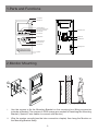
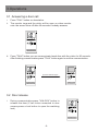
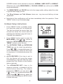
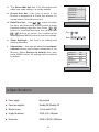
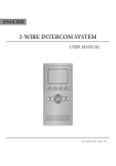
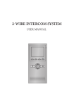
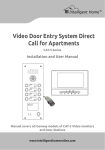
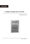
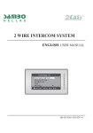
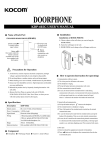
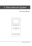
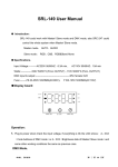
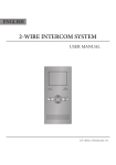
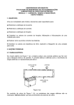
VM 35 User Manual
2
TALK
MENU
MONITOR
CONTENTS
1.Parts and Functions................................................. 1
2.Monitor Mounting..................................................... 1
3.Operations................................................................ 2
3.1 Answering a door call........................................ 2
3.2 Door release...................................................... 2
3.3 Entrance monitoring.......................................... 3
3.4 Intercom function............................................... 3
3.5 Image and Volume Adjust................................. 3
3.6 Basic Setup Instructions..................................... 4
4.Specifications........................................................... 5
1.Parts and Functions
LCD Screen
Microphone
UNLOCK Button
Second UNLOCK Button
Connection Port
Staircase Light Button
LED Indicator
2
CALL Button
MENU Button
Extend Port
ON
123456
TALK
MENU
MONITOR
DIP Switches
MONITOR Button
Direction Button
TALK Button
Mounting Hook
Speaker
145~160 cm
2.Monitor Mounting
i.
Use the screws to fix the Mounting Bracket on the mounting box.(fitting accesories
includes a Bracket (Two pieces of 4X25 screws are needed for fastening the Mounting
Bracket), Special 2 wire cables to connect with Monitor)
ii. Wire the system correctly(see the later connection chapter) then hang the Monitor on
the Mounting Bracket firmly.
-1-
3.Operations
3.1 Answering a door call
i. Press "CALL" button on doorstation.
ii. The monitor rings,and the visitor will be seen on video monitor.
note: the screen turns off after 40 seconds if nobody answers.
2
TALK
MENU
MONITOR
iii. Press "TALK" button,you can communicate hands free with the visitor for 90 seconds.
After finishing communication,press "TALK" button again to end the communication.
2
2
press TALK button again
TALK
MENU
MONITOR
finish the communication
TALK
MONITOR
MENU
3.2 Door release
i.
During communication,press "UNLOCK" button to
release the door.(If two locks connected to door
camera,press a lock button to open the matching
lock)
2
TALK
-2-
MENU
MONITOR
3.3 Entrance monitoring
i.
Press "MONITOR" button when in standby.
1
4
2
A
3
1
ii. The screen will show the icon
, press
to
choose the first camera,the screen will display the
image from the first door camera.Similarly, Press
to choose the second one,Press
to choose
the third one, Press
to choose the fourth one.
4
2
2
2
3
TALK
MENU
MONITOR
TALK
MENU
MONITOR
iii. Press"MONITOR" button again to end monitoring.
3.4 Intercom function
i.
Intercom Function
Intercom Call
Press "CALL" button in standby mode to enter
intercom function page.
Inner Call
Direct Dial Guard Unit
Exit
ii. Intercom Call: User in one apartment can call
other apartments in the system. Use
/
to
select the item and press MENU button to enter
the Name List page. (the namelist will be created
automatically by the system). Selete a name on
the screen then press CALL Button to call.Use
/
button to scroll to Last / Next name list page.
note:1. Press "CALL" button again to redial. 2.
Press "TALK" button to cancel the call.
- Name List [01] Mr A
[02] Mr B
[03] Mr C
[04] Mr D
[05] Mr E
iii. Inner Call: If multi Monitors are installed in the same apartment, select Inner Call
all the other Monitors will ring at the same time, whichever Monitor answers the call,
conversation is started.
iv. Direct Dial Guard unit: A Monitor can be assigned as Guard Unit Monitor; when the
Guard Unit Monitor answers the call, conversation with the guard person is started..
3.5 Image and Volume Adjust
i.
During monitoring or talking, press
“MENU"button,the ADJUST MENU will be
displayed.
user
scene
5
Brightness
RGB
/
ii. Press
to decrease or increase the
value; Use
/
button to select the next
adjustment item.
iii. The first item is Scene mode selection: Total 4
-3-
4
Colour
2
Ring Volume
Talk Volume
6
SCREEN modes can be selected in sequence: NORMAL, USER, SOFT and BRIGHT.
Whenever you modify BRIGHTNESS or COLOUR, SCENE item will be set to USER
mode automatically.
iv. The BRIGHTNESS and COLOR item is for the image quality setting, adjust the value
to get the best image you like.
v.
The Ring Volume and Talk Volume items are ring tone and talking volume
adjustment.
vi. Note that all the modifications will be done immediately after the operation. Press
"MENU" button to quit the adjust page.
3.6 Basic Setup Instructions
i.
ii.
Press "MENU" button in standby mode,
the date/time page will be dispalyed.
The first line shows the current time, the
second line shows the current date and
weekday.(the date/time page will close in
3 munite if no operation).
Press "MENU" button again to enter the
MAIN MENU, Use
/
button to
select the SETUP MENU,and then press
"MENU" button to enter the item.
iii. The OUTDOOR TONE and INTERCOM
TONE item are for chord ring selection.
Press
/
to increase/decrease the
value. (alternatively, press the item itself
in sequence to increase/decrease the
value)
iv. AUTO RECORD:If the item is set to
ON, the Monitor will record the image
automatically in 2 seconds after the visitor
pressed the CALL Button on the Outdoor
station (optional).
v.
4
T h e A D VA N C E D S E T. . . i t e m i s f o r
advance settings. a password will be
asked before entering. The default
password is 2008.So you can press
/
button to increase/decrease the
value,Press
button to select the
/
location,after finishing,press MENU button
to enter next step.
-4-
monitor
intercom
setup
exit
Outdoor Tone
--
01
Intercom Tone
--
05
Monitor Time
-- 1min
Advanced Set...
Auto Record
--
OFF
Exit
Password: 0
***
vi. The Slave Addr Set item is for the master and
slave user code setting, it is set by installer.
vii. Guard Unit Set: if the item is set to 1, the
Monitor is assigned as a Guard Unit Monitor, for
normal users, it should be set to 0.
button to select
/
viii. Date/Time Set...: Use
the item. and then press MENU button to enter
time/date setting page.after that Press
/
button to increase/decrease the value,Press
button to select the location,after
/
finishing,press MENU button to save the settings.
ix. Other Settings...: this item is for adding and
deleting Remotes.
x.
Information...: this item will show the hardware/
software version and voltage information of the
Monitor. Select Restore to default item ,then
press MENU button. All settings will be restored
to default.
Slave Addr Set
--
0
Guard Unit Set
--
0
Date/Time Set...
Other Settings...
Information...
Exit
Time 1 1 : 3 5
Date 2 0 0 9 0 2 1 4
Hardware ver
0302
Software ver
0168
Voltage
22.4V
Manufacture
00.0T
Restore to default
Exit
4.Specifications
● Power supply:
bus powered
●● Power consumption:
Standby 2W; Working 5W
●● Monitor screen:
3.5 Inch color TFT-LCD
●● Display Resolutions:
320(R, G, B) x 240 pixels
●● Dimensions:
220(H)×105(W)×20(D)mm
-5-