1
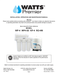
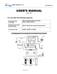
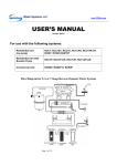
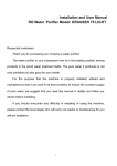
PWS2000 Water Dispenser User Manual PWS2000 Water Dispenser User Manual C130-00049 OCT2013 Page 1 PWS2000 Water Dispenser User Manual Notices & Safety Information Throughout this manual there are paragraphs set off by special headings. 1. 2. 3. Notice is used to emphasize installation, operation or maintenance information which is important, but does not present any hazard to persons or property. Caution is used when failure to follow directions could result in damage to equipment or property. Warning is used to indicate a hazard which could cause injury or death if ignored. The CAUTION and WARNING paragraphs are not meant to cover all possible conditions and situations that may occur. It must be understood that common sense, caution, and careful attention are conditions which cannot be built into the equipment. • To ensure proper operation of your dispenser, carefully follow the instructions in this manual. Do not use with water that is microbiologically unsafe or of unknown quality without adequate disinfection before or after the system. • Check and follow the applicable plumbing codes and ordinances when installing this equipment. Local codes may prohibit the discharge of acid or caustic solutions to drain. An extra solution tank should be used to neutralize the solution before discharging to drain. Follow local codes if they differ from this manual. • Regularly inspect the dispenser for water leaks. Water leaks can cause damage to home and property. • Only connect the power cord to a properly grounded outlet and do not use an extension cord. • Never pull the power plug from the outlet with a wet hand or allow the plug to get wet. • Keep the power cord out of heavy traffic areas. To avoid a fire hazard, never put the power cord under rugs, near radiators, stoves or heaters. • Do not use a damaged power cord or plug. If damaged, a qualified service technician must replace it. • To meet European CE requirements, fasten the unit to the floor with the expansion bolt M6x60. • This appliance is not intended for use by persons (including children) with reduced physical, sensory or mental capabilities, or lack of experience and knowledge, unless they have been given supervision or instruction concerning use of the appliance by a person responsible for their safety. Children should be supervised to ensure that they do not play with the appliance. This product should not be disposed with other household wastes throughout the EU. To prevent possible harm to the environment or human health from uncontrolled waste disposal, recycle it responsibly to promote the sustainable reuse of material resources. To return your used device, please use the return and collection systems or contact the retailer where the product was purchased. C130-00049 OCT2013 Page 2 PWS2000 Water Dispenser User Manual Table of Contents Notices & Safety Information .............................................................................. 2 Table of Contents ................................................................................................ 3 PWS2000 Series Water Dispenser Overview ....................................................... 4 Water Dispenser ......................................................................................... 4 UV Light System .......................................................................................... 4 Leak Detection System ................................................................................ 4 Filtration System ......................................................................................... 4 Main Storage Tank ...................................................................................... 4 Mechanical Components ............................................................................ 4 Unpacking ........................................................................................................... 5 Assembly Drawings.............................................................................................. 6 Installation .......................................................................................................... 8 Position & Level........................................................................................... 8 Install Filtration ........................................................................................... 9 Establish Water & Electrical Connections ................................................. 10 Flush Filters ............................................................................................... 11 Sanitize Dispenser ..................................................................................... 11 Turn ON HOT & COLD Switches ................................................................ 11 Record Installation Date............................................................................ 11 Operation .......................................................................................................... 12 Service and Maintenance .................................................................................. 13 General Maintenance ............................................................................... 13 Sanitize Dispenser ..................................................................................... 13 UV System Bulb Replacement ................................................................... 13 Reset Leak Detection System .................................................................... 14 Reset HOT Tank Element........................................................................... 14 Troubleshooting ................................................................................................ 15 Technical Specifications ..................................................................................... 16 Flow Diagrams ................................................................................................... 17 Electrical Diagram.............................................................................................. 18 Normal Service Replacement Parts.................................................................... 19 Warranty ........................................................................................................... 20 C130-00049 OCT2013 Page 3 PWS2000 Water Dispenser User Manual PWS2000 Series Water Dispenser Overview Thank you for purchasing the PWS2000 Series Water Dispenser. The PWS2000 Series brings a unique, fresh approach and a new look to point-of-use water treatment systems. The system’s contemporary color scheme complements every office environment. Unlike a bottled water cooler, incoming tap water is treated as it is needed, so the water is always fresh and great tasting. Best of all, there are no bottles to change and the supply is virtually unlimited. Water Dispenser Depending on model, your PWS2000 Series Water Dispenser is configured to supply a clean and pure supply of HOT, COLD, and if equipped, AMBIENT water. The heating system consists of a 0.5 gallon (2 liter) stainless steel tank fitted with a 500 watt heating element and protected by a resettable bi-metal overload thermostat. The HOT water being dispensed is factory set to 185°F (85°C). COLD water is chilled with a high capacity compressor using R134a non-ozone depleting refrigerant gas. This compressor is controlled by an electromechanical thermostat, which controls the water temperature in the 1 gallon (3.8 liter) stainless steel tank. The COLD water temperature is factory preset to a nominal 41°F (5°C). UV Light System Most models of the PWS2000 Series Water Dispenser are fitted with a UV-C band light system between the tank and dispenser spigot. This system is used to inhibit the growth of bacteria by compromising their DNA structure. When dispensing water, you will notice a pulsating UV INSIDE light which simulates the UV light system activation. The UV bulb is housed within a quartz sleeve which allows the UV light to pass through to the water. This bulb should be replaced every 12 months and the quartz sleeve removed and cleaned. Leak Detection System All models of the PWS2000 Series Water Dispenser are fitted with a leak detect system. This system will generate an audible and visual warning upon detecting water at the base of the unit due to failed tubing or connections. In addition, the system will automatically close the incoming water supply valve to prevent further damage. Filtration System The PWS2000 Water Dispenser is shipped from the factory with no internal filtration. Consult with your local dealer on the best filtration solutions for the local water conditions. Main Storage Tank Both HOT and COLD tanks are fed from a main 3 gallon (11 liter) storage reservoir located at the top of the water dispenser. This tank is fed directly from the filtration system and is protected from overflow by a redundant float system. Mechanical Components The dispenser is connected to the water supply by a 1/4” push-to-connect style bulkhead fitting. The entire internal water circuit and all components which come in contact with water are NSF Standard 61 approved. The molded panels are made from recyclable ABS plastic. All the ABS plastic panels are UV resistant and meet the standards of both CE and ETL. C130-00049 OCT2013 Page 4 PWS2000 Water Dispenser User Manual This manual includes information on the following PWS2000 Series Water Dispenser models. PWS2000- HC HC = Hot & Cold HAC = Hot, Ambient, & Cold AC = Ambient & Cold HA = Hot & Ambient 11RO 11RO = w/ UV 01RO = w/o UV 1 1 = 120VAC w/ US plug, 2 = 220VAC w/ Euro plug 3 = 220VAC w/ UK plug 4 = 100VAC w/ JPN plug 5 = 220VAC w/ CCC plug W B = Black G = Gray W = White Unpacking The PWS2000 comes completely assembled and ready to operate upon installation of the appropriate filtration cartridges. Remove the dispenser and save the carton and packaging materials. The carton contains the following items. Qty 1 1 1 1 1 1. 2. 3. 4. Item PWS2000 Series Water Dispenser Cup Holder M4 X 30 Tamper-proof Screw M6 X 60 Expansion Bolt User Manual Inspect the outer panels for any damage which may have occurred during shipment. To inspect the interior, remove the filtration service panel. Visually inspect for any wires, tubing, or fittings which may have come loose during shipment. Record the unit model and serial numbers in this manual for future reference. Record your water dispenser part number here: PWS2000Date purchased Date installed Products manufactured and marketed by SIMPLEMENTE AGUA SAS and its affiliates are protected by patents issued or pending in the United States and other countries. S.A reserves the right to change the specifications referred to in this literature at any time, without prior notice. C130-00049 OCT2013 Page 5 PWS2000 Water Dispenser User Manual Assembly Drawings Figure 1. Side Views 1. Top Service Panel 11. Status Indicator - Power 21. Fuse 2. Side Panel Right 12. Side Panel Left 22. Power Cord 3. Front Top Panel 13. Rear Service Panel 23. Thermostat for Cooling 4. Hot Water Pushbutton 14. ON/OFF Switch (HOT) 24. Cold Tank Drain 5. Spigot 15. Main PCB Cover 25.RO Waste Drain 6. Drip Tray 16. Condenser 7. Filtration Service Panel 17. Hot Tank Drain 8. Front Lower Panel 18. Supply Inlet 9. UV Simulation Display 19. Adjustment Feet 10. Cold Water Pushbutton 20. ON/OFF Switch (COLD) Top P C130-00049 OCT2013 Page 6 PWS2000 Water Dispenser User Manual Main Tank Primary Level Sensor Redundant Level Sensor UV Chamber COLD Tank HOT Tank Filter Manifold Inlet Valve Filter Cartridge Compressor Leak Sensor Figure 2. Exploded View Figure 3. Dimensions C130-00049 OCT2013 Page 7 PWS2000 Water Dispenser User Manual Installation Figure 4. Quick Start Guide. Position & Level 1. 2. 3. Locate the dispenser as close to the water supply and the electrical connections as possible. Level the dispenser using the adjustable leveling feet and built-in bubble indicator. Keep the dispenser at least 3 inches from the wall to ensure adequate airflow. WARNING TO COMPLY WITH CE STANDARDS, IT IS NECESSARY TO FASTEN THE UNIT TO THE FLOOR. THE APPLIANCE SHOULD NOT BE EXPOSE D TO DIRECT SUNLIGHT, HEAT SOURCES, OR AN AMBIENT AIR TEMPERATURE ABOVE 90°F (32°C) OR BELOW 37°F (3°C) OR STRUCTURAL DAMAGE MAY OCCUR. 4. To comply with CE standards, it is necessary to fasten the unit to the floor with an M6x60 expansion bolt. 1) Locate and drill a 43mm deep hole using an alloy drill bit with 9mm diameter. 2) Install the flat pad, the spring washer and the nut to the bolt, and then insert into the hole. C130-00049 OCT2013 Page 8 PWS2000 Water Dispenser User Manual 3) Remove the Filtration Service panel and locate the alignment hole on the base plate. 4) Align the appliance with the expansion bolt using the hole in the base plate. 5) Using a wrench, secure the appliance to the expansion bolt. 6) Reinstall the Filtration Service panel. Figure 5. Dispenser Leveling Feet and Installing the Expansion Bolt 5. Your PWS2000 Water Dispenser comes complete with a built-in cup holder under the water dispenser section. This holder is designed to hold up to 20 standard size cups with a top diameter of between 2.8” and 3.0” (71 – 76mm). Install Filtration The PWS2000 Water Dispenser is shipped from the factory with no internal filtration installed. Consult with your local dealer on the best filtration solutions for the local water conditions and follow the manufacturer’s instructions on their installation, use, and servicing. Typical solutions include SED for the reduction of particulates, CTO for chlorine, taste, and odor, and RO for the filtration of waterborne microorganisms, heavy metal, and other inorganic contaminants. The steps below apply to a typical twist-lock style filtration system. 1. 2. 3. 4. 5. 6. 7. Open the filtration service panel. Mount the manifold to the dispenser back-plate using two mounting screws Connect the yellow (supply water) tube to the inlet port of the manifold. Connect the blue tube (filtered water) to the manifold outlet port. Insert both filter cartridges to the manifold by pushing up and turning clockwise. Turn on water supply and check for leaks. Reinstall the filtration service panel. Figure 6. Example of 2-stage twist-lock filtration system installation. C130-00049 OCT2013 Page 9 PWS2000 Water Dispenser User Manual 1. 2. Open the filtration service panel. Mount the manifold to the dispenser back-plate using two mounting screws 3. Connect the yellow (supply water) tube to the inlet port of the manifold. 4. Connect the blue tube (filtered water) to the manifold outlet port. 5. Connect the red tube (RO drain) between the cartridge and the drain port on the dispenser. Ensure that the flow restrictor is properly sized and installed! 6. Insert filter cartridges to the manifold by pushing up and turning clockwise. 7. Turn on water supply and check for leaks. 8. Reinstall the filtration service panel. Figure 7. Example of 3-stage twist-lock RO filtration system installation. Establish Water & Electrical Connections The dispenser contains push-to-connect type fittings on the dispenser rear for the water supply and RO drain. These fittings accept ¼” polypropylene plastic tubing. If copper tubing is to be used, then these fittings must be replaced with a metal design. In addition, two drain ports are provided for the HOT and COLD tanks. 1. 2. Connect a clean, soft water supply to the unit. Pressure must be 40-60psi (2.8-4.1 bar) and at a temperature no more than 105°F (41°C). Flush the water supply feed until it runs clear before making connection to the dispenser. CAUTION DO NOT CONNECT THE DISPENSER TO A WATER LINE WHICH EXCEEDS 105°F (41°C) AS STRUCTURAL DAMAGE MAY OCCUR. A PRESSURE REGULATOR MUST BE USED FOR WATER SUPPLIES THAT EXCEED 60 PSI (4.1 BAR), ARE UNKNOWN, OR HAVE PRESSURE FLUCTUATIONS. THIS SHOULD BE INSTALLED ON THE WATER SUPPLY BEFORE THE DISPENSER INLET. 3. Plug the dispenser into the wall outlet and verify that the green PWR status indicator is ON. A fuse located on the rear service panel protects the internal circuits from damage. CAUTION DAMAGE TO THE DISPENSER WILL RESULT IF HOT AND COLD SWITCHES ARE TURNED ON WITHOUT WATER INSIDE THE TANKS IF THE UNIT WAS PLACED ON ITS SIDE, IT MUST STAND UPRIGHT FOR A MINIMUM OF 2 HOURS BEFORE OPERATION TO ALLOW THE COMPRESSOR TO STABILIZE C130-00049 OCT2013 Page 10 PWS2000 Water Dispenser User Manual Flush Filters All filters must be flushed prior to use per manufacturer’s instructions. When using twist lock style cartridges, this process may be combined with the initial dispenser sanitizing process below. Sanitize Dispenser Your dispenser is sanitized at the factory prior to shipment. However, it is recommended to sanitize again before using your dispenser for the first time. Failure to do so may result in poor water taste. This is best accomplished as outlined below (for a typical 3-stage filtration system) using the sanitizing kit from the dispenser supplier. 1. 2. 3. 4. 5. 6. 7. 8. 9. 10. 11. 12. 13. 14. 15. Soak RO cartridge in clean water while the dispenser is being sanitized. Ensure both water connections – supply and RO drain – are made at the rear of the dispenser. Open top service panel to gain access to the main storage tank and UV bulb. Open filtration service panel, locate, and install the SED and CTO filters in positions 1 and 2 of the manifold. Locate the SAN cartridge and pipette from the Sanitization kit. Using the pipette, draw 2ml of unscented, liquid bleach (5% sodium hypochlorite) and dispense into the SAN cartridge. Insert the SAN cartridge into position 3 of the manifold. Slowly turn ON the water supply until the main storage tank is ½ full then turn OFF. Carry out a visual inspection for any water leaks. Lift the main storage tank lid taking care not to damage the level sensor. Wearing gloves and using a clean, lint-free cloth, thoroughly wipe down the inside of the main storage tank. Let stand for ten minutes. Slowly turn ON the water supply. Depress the dispenser buttons (alternate between HOT and COLD sides) to allow the solution to run through the spigot and associated lines. Drain the system until the chlorine bleach is no longer detected at the spigot. Remove the SAN cartridge and replace with the RO cartridge. NOTE REMEMBER TO CONNECT THE RO DRAIN LINE TO THE RO CARTRIDGE. ALSO ENSURE THAT THE BLUE FLOW RESTRICTOR IS VISIBLE INSIDE THE RO DRAIN LINE 16. Record service date on the inside filtration panel for future reference. 17. Replace the filtration service panel. Turn ON HOT & COLD Switches With all tanks completely filled with water, both the HOT and COLD switches at the rear of the dispenser should be turned ON. It will take approximately 30 minutes for the HOT water and 60 minutes for the COLD water to reach their temperature presets. NOTE IF AN RO FILTRATION IS BEING USED ALLOW 45 MINUTES TO COMPLE TELY FILL ALL TANKS. Record Installation Date In order to ensure proper maintenance of your dispenser, a service tag is provided on the inside of the filtration panel. This will ensure that maintenance intervals can be recorded and scheduled. C130-00049 OCT2013 Page 11 PWS2000 Water Dispenser User Manual Operation Your PWS2000 Series Water Dispenser contains a simple, intuitive user interface for operation and status. All buttons are backlit and a nightlight is provided in the dispenser area. UV light simulator COLD button HOT button System fault indicator Night light POWER status Figure 8. User Interface Button/LED POWER Indicator ON Dispenser powered OFF Dispenser unpowered Flashing n/a HOT Illuminated Pushbutton Water heating n/a AMBIENT illuminated Pushbutton n/a COLD Illuminated Pushbutton Water chilling UV Simulation Light UV system ready* Dispenser unpowered or water heated to preset temperature Dispenser unpowered or ambient water ready to dispense Dispenser unpowered or water chilled to preset temperature UV system ready UV Fault Indicator UV bulb needs replacement UV system ready n/a n/a UV system active System fault – i.e. leak, short-circuit *ON only when user is in front of dispenser. NOTE A CHILD SAFETY LOCKOUT IS PROVIDED FOR THE HOT WATER SIDE. THE BUTTON MUST BE HELD FOR 3 SECONDS UNTIL A BEEP IS HEARD. PRESS THE BUTTON AGAIN FOR WATER TO DISPENSE C130-00049 OCT2013 Page 12 PWS2000 Water Dispenser User Manual Service and Maintenance Once assembled, installed, and flushed properly, your PWS2000 Water Dispenser will provide years of trouble-free operation. Normal service should only be carried out by a trained service professional. Depending on usage, the filtration cartridges should be replaced every six (6) months or as directed by their manufacturer. In addition, models with the UV system option should have the UV bulb replaced every twelve (12) months. SERVICE NOTES DO NOT CLEAN THIS APPLIANCE WITH A WATER JET. RUBBER GLOVES MUST BE WORN WHEN HANDLING THE FILTERS, STORAGE TANKS, UV QUARTZ SLEEVE, OR ANY COMPONENTS THAT HAVE CONTACT WITH THE DRINKING WATER. General Maintenance 1. Wipe all surfaces on the front panels, dispenser buttons, dispenser area, faucet, and drip tray with a bacterial cleaning wipe or spray. 2. Remove and clean the drip tray and grill. If the grill is damaged or heavily stained it should be replaced. 3. Wipe away any dust which may have accumulated on the condenser grill behind the dispenser. 4. Drain all tanks after long periods of non-use. 5. On RO models periodically inspect the flow restrictor to ensure it is clean an unrestricted. WARNING TAKE PRECAUTIONS WHEN DRAINING THE HOT WATER. Sanitize Dispenser All tanks should be sanitized at regular intervals, especially after a long period of non-use. accomplished using a sanitization kit from the dispenser supplier as outlined on page 11. This is best UV System Bulb Replacement The UV bulb is located under the top service panel and should be replaced every twelve months. 1. Disconnect power to the dispenser. 2. Turn OFF the water supply and activate the dispenser buttons to relieve any pressure in the system. 3. Turn OFF the HOT and COLD switches at the dispenser rear. 4. Drain all tanks using the drain ports at the dispenser rear. 5. Open top service panel to gain access to the main storage tank and UV bulb. WARNING NEVER LOOK INTO THE UV LIGHT AS UV RADIATION IS DANGEROUS TO THE EYES AND SKIN. DO NOT TOUCH THE UV THE QUARTZ SLEEVE WITH BARE HANDS. THE TEMPERATURE OF THE WATER FLOWING AROUND THE UV BULB IS HOT. 6. 7. 8. Unplug the UV electrical connector from the UV assembly. Unscrew the top four screws and carefully lift out the UV bulb from UV assembly. Unscrew the quartz sleeve by turning counterclockwise. C130-00049 OCT2013 Page 13 PWS2000 Water Dispenser User Manual 9. 10. 11. 12. 13. Using a clean, lint-free cloth, thoroughly wipe down the outside of the quartz sleeve and reinstall. Install a new UV bulb (FilterPro part number C080-00030) into the UV assembly and fasten the top four screws. Plug in the UV electrical connector to the UV assembly. Reconnect power to the dispenser. Check that the UV lamp is functioning by observing a blue glow from the UV assembly inlet or outlet (Note that the lamp only operates when the dispenser buttons are pressed). 14. Reinstall top service panel. 15. Slowly turn ON the water supply. 16. When all tanks are filled, turn ON the HOT and COLD switches at the dispenser rear. Reset Leak Detection System All models of the PWS2000 Series Water Dispenser are fitted with a leak detect system which will generate an audible and visual warning upon detecting water at the base of the unit due to failed tubing or connections. In addition, the system will automatically close the incoming water supply valve to prevent further damage. Normal operation will return once the source of the leak is removed. Reset HOT Tank Element All models of the PWS2000 Series Water Dispenser are fitted with a thermal overload switch to protect the HOT tank system. If an audible “click” is heard within 5 minutes of turning ON the HOT on/off switch, OR if the dispenser fails to make HOT water, then this switch has tripped. The overload switch is on the side of the hot tank as shown below and must be manually reset. Ensure that the dispenser is unplugged before accessing this switch. HOT ON/OFF Switch Overload Switch Figure 9. HOT Tank Reset Button Location C130-00049 OCT2013 Page 14 PWS2000 Water Dispenser User Manual Troubleshooting Symptom Possible Cause No Power / Power status indicator OFF No electric current flowing External circuit breaker has tripped Blown fuse Tanks not filling during initial setup External water supply is turned OFF Leak detection system activated Blockage in filtration system RO filtration installed Check external water supply valve for proper position Remove source of leak and reset system Remove source of blockage Allow 45 minutes to fill tanks when RO filtration installed Dispensed water is neither HOT nor COLD HOT/COLD switches turned OFF Check position of the HOT/COLD switches on the dispenser rear panel No, or low flow from COLD dispenser – HOT is OK Water inside the cold tank frozen Check to ensure that the thermostat is at the factory setting Turn OFF the COLD switch for 4 hrs to melt ice inside tank No or low flow from HOT dispenser – COLD is OK HOT water tank needs to be de-scaled De-scale HOT water tank If problem persists, consult with your authorized service provider about adding a de-scaling filter cartridge No or low flow from both HOT and COLD dispensers Filter cartridges may need changing Low pressure from water supply Change filter cartridge(s) Check water supply pressure Dispensed HOT water is cold HOT tank overload switch has tripped Follow the instructions in this manual on how to reset the HOT water tank Dispensed COLD water is warm Dispenser COLD switch is OFF Dispenser is not positioned correctly Condenser refrigerant is low Check that the COLD switch on the dispenser rear panel is in the ON position Check to ensure the dispenser is at least 3” from the wall, not in direct sunlight or in a room with high ambient temperature Dispensed water has a “bad” taste Dispenser not sanitized Filters not flushed Sanitize the dispenser If the bad taste persists taste the water coming directly from the filter cartridge and change as necessary If still bad change the filter, or contact your service provider C130-00049 OCT2013 Solution Check outlet and plug for proper connection Check external circuit breaker Check fuse at rear of dispenser and replace as necessary Page 15 PWS2000 Water Dispenser User Manual Technical Specifications Cabinet Color Black, white, gray Material Metal side panels, ABS front panels Dimensions 16.6” x 17.1” x 48.8” (422 x 435 x 1240mm) Empty Weight 65 Lbs (29.5 Kg) Water Connections 1/4" push to fit style Water Dispenser Selections Hot & Cold standard Storage Tank Material Stainless Steel (plastic for 3 gallon internal storage tank) Hot Cold Temperature Range 176-185°F (85 °C) Storage Capacity 0.5 Gallons (2 Liters) Heating Capacity Min. 0.26 Gallon (1000 ml) dispensed @160°F (70°C) Temperature Range 39 – 46°F (4 - 8°C) Storage Capacity 1 Gallons (3.8 Liters) Chilling Capacity Min. 0.26 Gallon (1000 ml) dispensed @40°F (5°C) Min/Max Water Pressure 40 - 60 psi (2.8 – 4.1 bar) User Interface Electronic Controls / Status Indicators Illuminated Pushbutton / Power LED Adjustable Temperature Range No ON/OFF Switch HOT and COLD Safety Features Child-proof HOT Water Dispenser Standard Leak Detect with Auto Shutoff Standard Antimicrobial Coating Select models only Bacterial Growth inhibitor Models with UV option only Electrical Operating Voltage US version: 120 VAC/60Hz (700W) EUR version: 220-240VAC/50Hz (600-705W) Energy Consumption 0.932 KwH (normal operation) Environmental Refrigeration Gas R134a 1.4 Oz (40 grams) Decibels 41 dB Approvals ETL to UL 399 standard, CE C130-00049 OCT2013 Page 16 PWS2000 Water Dispenser User Manual Flow Diagrams Figure 10. Flow Diagram (HOT & COLD models) Figure 11. Flow Diagram (HOT, AMBIENT, and COLD models) C130-00049 OCT2013 Page 17 PWS2000 Water Dispenser User Manual Electrical Diagram Figure 12. Electrical Diagram (All models) MC: motor compressor H: Heater SOL1: Inlet valve SOL2: HOT inlet valve SOL3: COLD inlet valve SWL: compressor switch SWH: Heater switch C130-00049 OCT2013 SW1: HOT dispenser switch SW2: COLD dispenser switch LD: Water leak detector WLD: Water level detector OV: Low level control switch TH: Temperature control switch Page 18 PWS2000 Water Dispenser User Manual Normal Service Replacement Parts Filtration Parts, FilterPro Clean & Pure Twist Lock Brand TLSSH Manifold, single stage TLDSH Manifold, double stage TLRO3H-S-C Manifold, triple stage (series) TLROMC Cartridge, RO, 35GPD TLROROMC-75 Cartridge, RO, 75GPD TLSSC TLSC1 TLSC2 TLSAN Cartridge, sediment Cartridge, CTO level 1 Cartridge, CTO plus lead and cyst Cartridge, sanitization Water Dispenser Parts C080-00030 UV Bulb C080-00015 C030-00091 C030-00093 C030-00094 C010-00239 C080-00007 C080-00017 UV Ballast HOT Tank Assembly 120AVC HOT Tank Assembly 220AVC COLD Tank Assembly 3G Tank Assembly Transformer, 120VAC Transformer, 220VAC C080-00023 C080-00006 C010-00045 C010-00044 C010-00039 C030-00002 Fuse, 10A/120VAC Fuse, 5A/220VAC Drip Tray Grill, specify color Drip Tray, specify color Filtration Service Panel, specify color Left Side Panels, specify color C030-00003 C030-00001 C010-00240 C010-00055 C080-00028 C080-00052 Right Side Panels, specify color Lower Front Panel, specify color Cup Holder Assembly Drain Plug (supply) Inlet Solenoid Valve Ambient Outlet Solenoid Valve C080-00052 C080-00052 C080-00024 C080-00040 Cold Outlet Solenoid Valve Hot Outlet Solenoid Valve Electric Ball Float Valve Mechanical Float Valve C130-00049 OCT2013 Page 19 PWS2000 Water Dispenser User Manual Warranty This water treatment system is guaranteed to the original user only to be free of defects in materials and workmanship for a period of one (1) year from the date of purchase, or initial lease, but in no event longer than twenty-four (24) months from the date of manufacture. S.A will not be liable for any cost of removal, installation, transportation, or any other charges which may arise in connection with a warranty claim. S.A will not be liable for damage or wear to products caused by abnormal operating conditions, accident, abuse, misuse, unauthorized alteration or repair, or if the products were not installed in accordance with S.A’s printed installation and operating instructions, or for any damage caused by hot water, freezing, flood, fire, or acts of God. In the event of a claim for warranty, the defective part must be returned to S.A, together with proof of purchase, installation date, failure date and supporting installation data. Any defective part returned to S.A incorporated must be sent freight prepaid. Documentation to support the warranty claim and/or a Return Authorization form must be included, if so instructed. S.A, at its sole discretion, will determine whether to correct the defect or replace the unit, or will request that the unit be returned to S.A. Provided a claim is based on a defect in materials or workmanship; and provided the claim is made within the warranty period; and provided the user has used and maintained the equipment in accordance with the manufacturer’s instructions, S.A will replace the parts free of charge. If the unit is returned to S.A for repairs, the end user will pay the cost of freight in both directions. This warranty does not apply to damage caused by, or resulting from, shipping, accident, alteration, misuse or abuse, unauthorized or improper installation, or to units used outside the country where the unit was rented or purchased. The effects from chlorine corrosion, scaling and normal wear are specifically excluded from this warranty. S.A hereby disclaims any and all implied warranties including, but not limited to, the implied warranties of merchantability and fitness for a particular purpose. The manufacturer or its agents shall not be liable for consequential damages, whether economic or otherwise, resulting from breach of this limited warranty. Failure to follow all instructions for operation and maintenance provided with this unit voids the warranty. This warranty gives you specific legal rights and you may also have other rights which may vary from country to country. C130-00049 OCT2013 Page 20