1
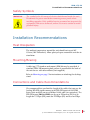
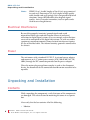
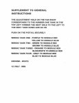
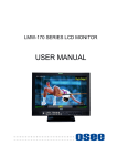
RDM-173-3G
Rack Drawer Dual Input, LCD, Audio/
Video Monitor
User Guide
Part Number 821099, Revision A
© 2013 Wohler Technologies, Inc. All rights reserved.
This publication is protected by federal copyright law. No part of this publication may be
copied or distributed, stored in a retrieval system, or translated into any human or computer
language in any form or by any means electronic, mechanical, manual, magnetic, or otherwise,
or disclosed to third parties without the express written permission of Wohler Technologies.
Reproduction
Licensed users and authorized distributors of Wohler Technologies, Inc. products may copy
this document for use with Wohler Technologies., Inc. products provided that the copyright
notice above is included in all reproductions.
Customer Support
Wohler Technologies, Inc.
31055 Huntwood Avenue
Hayward, CA 94544
www.wohler.com
Phone: 510-870-0810
FAX: 510-870-0811
US Toll Free: 1-888-596-4537
(1-888-5-WOHLER)
Web: www.wohler.com
Sales: [email protected]
Support: [email protected]
Disclaimers
Even though Wohler Technologies, Inc. has tested its equipment and software, and reviewed
the documentation, Wohler Technologies, Inc. makes no warranty or representation, either
express or implied, with respect to software, documentation, their quality, performance,
merchantability, or fitness for a particular purpose.
Wohler Technologies, Inc. reserves the right to change or improve our products at any time and
without notice.
In no event will Wohler Technologies, Inc. be liable for direct, indirect, special, incidental, or
consequential damages resulting from any defect in the hardware, software, or its
documentation, even if advised of the possibility of such damages.
Some states do not allow the exclusion or limitation for incidental or consequential damages, so
the above exclusion or limitation may not apply to you.
Printing
This document is intended to be printed on a duplex printer, such that the copy appears on
both sides of each page. This ensures that all new chapters start on a right-facing page.
This document looks best when printed on a color printer since some images may be indistinct
when printed on a black and white printer.
Last Update
October 28, 2013
8 21 09 9 :
ii
RD M -1 73 -3 G U se r G u id e
© 2 01 3 Woh le r Te ch no lo g ie s, Inc . A ll ri g ht s re s e r v ed .
RDM-173-3G
Introduction
Overview
The RDM-173-3G dual input, LCD video monitors are highperformance, professional LCD monitors that support advanced 10-bit
digital processing technology with 3D comb filter and de-interlace,
accurate scaling engine, GAMMA correction and color temperature
adjustments to achieve the best possible image display.
The RDM-173-3G supports 2-channel 3G/HD/SD-SDI, Y/C,
component, and CVBS signal inputs as well as a single HDMI signal
input. Each model can simultaneously display two signal inputs, with
three display modes including one full screen display, Picture-InPicture (PIP) displays and two Picture-By-Picture (PBP) uniform size
screen displays.
Topics
Topics
Introduction
Page
1
Safety
2
Installation Recommendations
3
Unpacking and Installation
4
Features
9
Front Panel Features
10
Rear Panel Features
13
Using the Menu System
17
Specifications
30
Technical Function Overview
33
82 10 99 :
RD M -1 73 -3 G U se r G u id e
© 2 0 1 3 Wo hl e r Te c hno lo g i e s, In c. A ll r ig h ts re se r v ed .
1
RD M - 1 7 3- 3G
Sa f e t y
Safety
Important Safety Instructions
IMPORTANT:
1.
Read, keep, and follow all of these instructions; heed all warnings.
2.
Do not use this equipment near water, rain or moisture.
3.
Use only a dry cloth to clean the equipment.
4.
Do not install near any heat source such as a radiator, heat register,
amplifier, or stove.
5.
Do not attempt to plug the unit into a two-blade outlet (with only
two prongs of equal width).
By design, these monitors will only plug into a three-prong outlet for
your safety. If the plug does not fit into your outlet, contact an
electrician to replace the obsolete outlet.
6.
Protect the power cord from being walked on or pinched,
particularly at plug’s source on the equipment and at the socket.
7.
Use only the attachments/accessories specified by the
manufacturer.
8.
Unplug the equipment during lightning storms or when unused
for long periods of time.
9.
Use of a cart is neither recommended nor approved by Wohler.
10. Refer all servicing to qualified service personnel. Servicing will be
required under all of the following conditions:
8 21 09 9 :
2
•
The equipment has been damaged in any way, such as when
the power-supply cord or plug is damaged.
•
Objects have fallen onto the equipment; or the equipment has
been exposed to rain or moisture, or liquid has been spilled
onto the equipment.
•
The equipment does not operate normally.
•
The equipment has been dropped.
RD M -1 73 -3 G U se r G u id e
© 2 01 3 Woh le r Te ch no lo g ie s, Inc . A ll ri g ht s re s e r v ed .
RDM-173-3G
I n s t a l la t io n R e c om m e n d a t io n s
Safety Symbols
WARNING:
The symbol to the left warns of electric shock hazard inside the unit.
Disconnect the power cord before removing access panels when
installing upgrades. Only qualified service personnel are to operate the
equipment with covers removed, and are to exercise caution to avoid
personal injury.
Installation Recommendations
Heat Dissipation
The ambient temperature around the unit should not exceed 40°
Celsius (104° Fahrenheit). Allow plenty of space around the unit for air
circulation.
Mounting/Bracing
A table top (-TT) stand or rack mount (-RM) kit may be provided. A
standard VESA 100 mounting hole pattern is provided on the back of
the unit for use with other mounts (not supplied).
Refer to Mounting on page 5 for instructions on attaching the desktop
stand.
Connections and Cable Recommendations
We recommend that you limit the length of the cables that you use for
feeding HD-SDI signals sources to the HD-SDI inputs of the HDM
Series units and that you use a Belden 1694A cable (or equivalent). The
HD-SDI inputs (IN1 and IN2) can be up to 150 meters (492 feet) in
length for 1.5 Gbps (HD), more for 270 Mbps (SD) and less for 3Gbps.
82 10 99 :
RD M -1 73 -3 G U se r G u id e
© 20 13 Wo hl e r Te c hn ol og i e s , In c . A l l r ig h ts re se rv ed .
3
RD M - 1 7 3- 3G
U n p a ck in g a n d I n s t a ll a t io n
Note:
HDMI 1.3 or 1.4 cable lengths of 2m (6 feet) are guaranteed
to work well. Four meters (12 feet) lengths of high quality
cable should work well enough, but is not guaranteed for all
situations. Longer HDMI cables often degrade signal
quality. Active extender transmitter/receiver pairs can be
used to cover long distances.
Electrical Interference
Be careful to properly terminate/ground signals and avoid
mismatched cable types and other similar causes of undesired
reflections in digital signal systems. If severe enough, such reflections
can result in corruption of the digital data stream. As with any audio
equipment, maximum immunity from electrical interference requires
the use of shielded cable. The internal circuitry ground is connected to
the chassis.
Power
The unit comes with a standard 12 VDC/5 A external power adapter
and connects an A/C mains power source (65W, 100 to 240 VAC, 50/
60Hz) through the IEC connector provided on the power adapter.
When the mains plug or appliance coupler is used as the disconnect
device, the disconnect device connection should remain accessible to be
operable.
Unpacking and Installation
Contents
While unpacking the components, verify that none of the components
are damaged. The selected stand or mounting kit comes in a separate
box.
Also verify that the box contains all of the following:
• Monitor
8 21 09 9 :
4
RD M -1 73 -3 G U se r G u id e
© 2 01 3 Woh le r Te ch no lo g ie s, Inc . A ll ri g ht s re s e r v ed .
RDM-173-3G
U n p a c k in g a nd I n s t a ll a t io n
• Adapter (12 VDC)
• Power cord
• User guide CDROM
• Warranty card
Mounting
The RDM-173-3G monitor comes standard with a rack mounted
drawer. It is to be installed using the following steps:
1.
Withdraw the monitor from its drawer cage by unscrewing the
front panel captive fasteners and pulling the handle out toward
you.
2.
Push the catches inward on both sides to release and pull the
monitor with the inner slides to extract the monitor from the cage
as shown in Figure 1–1:
Figure 1–1
Drawer Release Catches
One of two catches
3.
As shown in Figure 1–2, set the monitor assembly aside for
safekeeping until the cage assembly is installed in the rack.
82 10 99 :
RD M -1 73 -3 G U se r G u id e
© 20 13 Wo hl e r Te c hn ol og i e s , In c . A l l r ig h ts re se rv ed .
5
RD M - 1 7 3- 3G
U n p a ck in g a n d I n s t a ll a t io n
Figure 1–2
4.
Set Monitor Assembly Aside
The cage for the drawer must be attached at both the front and
back of the rack. As shown in Figure 1–3 and Figure 1–4, the cage
depth can be adjusted for rack depths of 18 to 21 inches. If the rack
is within 2 inches deeper or shallower, spacers can be used to fill
the gap for secure mounting. Female-female threaded standoffs or
hollow spacers and thru-bolts work well.
Figure 1–3
Drawer Cage
18 - 21 inch depth
8 21 09 9 :
6
RD M -1 73 -3 G U se r G u id e
© 2 01 3 Woh le r Te ch no lo g ie s, Inc . A ll ri g ht s re s e r v ed .
RDM-173-3G
U n p a c k in g a nd I n s t a ll a t io n
IMPORTANT:
Very deep racks require wire or strap hangers secured to rack walls to
support the weight at the rear.
5.
If there is enough vertical space in the rack to insert the entire cage,
loosen but do not remove the screws shown in Figure 1–4 to allow
adjustment for depth. However, if vertical space is tight, remove
the two screws on each side, as shown in Figure 1–4, to separate
the rear mounting from the cage. Retain the flange and screws.
Figure 1–4
IMPORTANT:
Front & Back Separation / Adjustment
6.
Steps 6 and 7 will be easier to perform if two people are working
together. Mark the cage mounting locations on front and rear rack
rails. Ensure it will be level front-to-back and side-to-side.
7.
Slide the front section into the rack enclosure. If you separated the
front and rear cage section in Step 5, join them by engaging the
inner and outer slide rails. Attach the rack rails with rack screws
you provide. Secure the rear flanges as required. Tighten the
adjustment screws shown in Figure 1–4 on both sides.
Flypacks or vehicle mountings need to be shock and vibration resistant
in all axes to withstand transport stresses.
8.
Place the inner slides of the monitor assembly you set aside in Step
3 into the cage outer slides. Push the entire assembly in until
catches (shown in Figure 1–1) engage. The monitor can now be
tilted up into the vertical viewing position at this point. Figure 1–5
82 10 99 :
RD M -1 73 -3 G U se r G u id e
© 20 13 Wo hl e r Te c hn ol og i e s , In c . A l l r ig h ts re se rv ed .
7
RD M - 1 7 3- 3G
U n p a ck in g a n d I n s t a ll a t io n
shows the RDM-173-3G tilted up into viewing position, although it
is shown outside of the rack enclosure for clarity. You can see the
connectors in this figure.
Figure 1–5
9.
RDM-173-3G in Viewing Position
Run the power and signal wiring through the cage. Connect the
wiring at the monitor end. Locate the wiring so that it will not get
pinched when closing and opening the drawer. Use adhesive
tiedowns and cable ties to secure wiring on monitor back and key
points along the route, as required. Spiral wrap sleeving is
recommended to protect cable bundles and form neat service
loops. Check wiring/loop travel in open and closed positions
again. (Adjustments may be needed to allow the cables to flex
smoothly.)
10. Connect signal and power wiring at source end. The monitor will
begin working when the power switch (hidden from view below
DC jack) is set to the "1" (ON) position.
8 21 09 9 :
8
RD M -1 73 -3 G U se r G u id e
© 2 01 3 Woh le r Te ch no lo g ie s, Inc . A ll ri g ht s re s e r v ed .
RDM-173-3G
F ea t u r e s
Features
The RDM-173-3G monitor provides the following features:
• 178° viewing angle
• Multi-format analog and digital audio signals
• Adjustment of the parameters for each channel
• High-quality waveform or vector monitoring (as SUB input)
• Embedded SDI or stereo analog audio through speakers or
headphones
• Audio bar graph meters, up to sixteen
• Stereo analog audio line output of selected channel
• Area, safety, and center markers
• Closed captions for CVBS
• Pre-set or user-adjustable color temperature per channel
• Time code for SD/HD-SDI in ANC-packet form and D-VITC
• Dynamic OSD/IMD tally
82 10 99 :
RD M -1 73 -3 G U se r G u id e
© 20 13 Wo hl e r Te c hn ol og i e s , In c . A l l r ig h ts re se rv ed .
9
RD M - 1 7 3- 3G
F r o nt P a n el F e a t u r e s
Front Panel Features
The following feature descriptions refer to Figure 1–6 below.
Figure 1–6
RDM-173-3G Front Panel (PIP)
Audio Level
Meters
Status - Sub
LED Tally
Status - Main
Main Input
Buttons
IMD
PIP display
mode
• Status: The status is displayed in the upper left corner for the main
window and in the upper right corner for the sub-window. It
includes the input channel number and signal format. Operation is
defined in the DISPLAY menu.
• Level Meters: Displays up to 16 channels, in horizontal or vertical
orientation. Define the meters setup in the AUDIO SOURCE and
METER DISPLAY menu options.
• IMD: The 16 characters of the in-monitor display (IMD) can be
displayed in red, green, yellow, or white. OSD CONFIG IMD
8 21 09 9 :
10
RD M -1 73 -3 G U se r G u id e
© 2 01 3 Woh le r Te ch no lo g ie s, Inc . A ll ri g ht s re s e r v ed .
RDM-173-3G
F r o n t P a n el F ea t u r e s
DISPLAY, IMD COLOR, and IMD CHAR define the static operation.
The IMD menu defines the dynamic IMD and OSD tally operations.
• Timecode: The display format for the timecode is HH: MM: SS: FF.
In the event no timecode is available, the monitor will display
--:--:--:--. Time code is currently available for SD/HD-SDI ANCpacketized only.
• Input: Pressing this button displays the Source menu. Further
presses cycle through available main video inputs. Alternately the
Up/Dn keys can be used.
• F1 through F5: These buttons serve as programmable hot keys.
Pressing a Function key displays the Function menu. Pressing the
key again toggles the state of that function. Refer to the Function
Key Menu on page 26 for details.
• Menu: Pressing this button displays the on-screen display (OSD)
Menu. Press MENU again to revert one menu level or exit out of
MENU mode.
• Up and Down: After pressing the MENU button, press Up or
Down to move within submenus.
• ENTER: After pressing the MENU button, pressing this button
selects the current menu or menu option. Changes are previewed,
but not saved, until you press the ENTER button again.
When the OSD Menu is not displayed, you can press the ENTER
button to quickly adjust the following parameters.
•
VOLUME :
Adjusts the volume from 0 to 30.
•
BRIGHTNESS:
•
CONTRAST:
•
CHROMA:
Adjusts the video brightness from 0 to 100,
where 50 is the typical value.
Adjusts the image contrast from 0 to 100, where
50 is the typical value.
Adjusts the color saturation from 0 to 100, where
50 is the typical value.
• Power LED: Lights red in standby mode and green when on. When
no main input signal is present, it blinks green.
• POWER (front): Toggles the monitor to on or standby mode.
82 10 99 :
RD M -1 73 -3 G U se r G u id e
© 20 13 Wo hl e r Te c hn ol og i e s , In c . A l l r ig h ts re se rv ed .
11
RD M - 1 7 3- 3G
F r o nt P a n el F e a t u r e s
• Waveform/Vector: In PIP or PBP screen modes, the SUB window
displays the waveform or vector, as defined in the Display Menu on
page 22 and Config Menu on page 23.
Figure 1–7
RDM-173-3G Waveform Display (PBP)
Main Input (in PBP
display mode)
8 21 09 9 :
12
RD M -1 73 -3 G U se r G u id e
© 2 01 3 Woh le r Te ch no lo g ie s, Inc . A ll ri g ht s re s e r v ed .
Waveform or Vector
as SUB Input (in
PBP display mode)
RDM-173-3G
R e a r P a n el F ea t u r e s
Rear Panel Features
Figure 1–8
RDM-173-3G Complete Rear Panel
82 10 99 :
RD M -1 73 -3 G U se r G u id e
© 20 13 Wo hl e r Te c hn ol og i e s , In c . A l l r ig h ts re se rv ed .
13
RD M - 1 7 3- 3G
Re a r Pa n e l F e a t u r es
Figure 1–9
RDM-173-3G Rear Panel - Lower Right
• DC IN (jack): Accepts power plug from the included 12 VDC
power adapter.
• Power (Rocker Switch not shown, near DC IN): Turns power to
the monitor on (1) or off (0).
• Audio Inputs (4 RCA): Each input pair (one for each channel)
accepts standard analog audio.
• GPI (RJ-45): Tally input. Refer to Figure 1–11 on page 16 and Table
1–1 on page 16 for connection details. Refer to the GPI Menu on
page 27 for selectable functions.
• Headphones: This 1/8” jack receives a standard mini-headphone
plug and provides stereo audio from the last video channel selected.
Inserting a plug here, wired or not, will mute the speakers.
8 21 09 9 :
14
RD M -1 73 -3 G U se r G u id e
© 2 01 3 Woh le r Te ch no lo g ie s, Inc . A ll ri g ht s re s e r v ed .
RDM-173-3G
R e a r P a n el F ea t u r e s
• Ethernet (RJ-45): Network interface for upgrades and dynamic
tally/UMD.
• RS485 Port (RJ-45): Input connector for external control. Refer to
Figure 1–11 on page 16 and Table 1–2 on page 16 for connection
details.
Figure 1–10
RDM-173-3G Rear Panel - Upper Left
• SDI Video Inputs (2 BNC) and SDI Output (BNC): These inputs
and output receive 3G/HD/SD-SDI signals. The output produces a
regenerated 3G/HD/SD-SDI signal from the input selected as
Main.
• HDMI IN: Type A HDMI jack accepts non-DHCP HDMI signals in
standard broadcast video formats, It can also accept similar DVI-D
resolutions with an adaptor (not supplied).
• Line 1 Input (BNC): CVBS composite analog video.
82 10 99 :
RD M -1 73 -3 G U se r G u id e
© 20 13 Wo hl e r Te c hn ol og i e s , In c . A l l r ig h ts re se rv ed .
15
RD M - 1 7 3- 3G
Re a r Pa n e l F e a t u r es
• Line 2 Inputs: CVBS/Y (BNC), Pb/C (BNC), Pr (BNC), analog
composite, S-video, and component video.
Table 1–1
GPI Pin Out
Pin
1
2
3
4
5
6
7
8
Figure 1–11
Function
GPI 1
GPI 2
GPI 3
GPI 4
GPI 5
GPI 6
NC
GND
RJ45 Connector Pin Map
.
Table 1–2
Pin
1, 2
3
4
5
6
7, 8
8 21 09 9 :
16
RS485 Pin Out
RS485 In Terminal Signal
GND
TxRx+
RxTx+
NC
RD M -1 73 -3 G U se r G u id e
© 2 01 3 Woh le r Te ch no lo g ie s, Inc . A ll ri g ht s re s e r v ed .
RS485 Out Terminal
Signal
GND
TxRx+
RxTx+
NC
RDM-173-3G
U s i ng t h e M e n u S y s t e m
Using the Menu System
Configuring the RDM-173-3G monitor is accomplished in the Menu
System. Each of the menus is explained on this and the following
pages.
1.
Press the MENU button to display the menu.
2.
Use the Up and Down buttons to navigate through the submenus.
The submenus are:
•
STATUS MENU (Read-only)
•
INPUT SELECT MENU
•
MARKER MENU
•
AUDIO MENU
•
DISPLAY MENU
•
CLOSED CAPTION MENU
•
CONFIG MENU
•
COLOR TEMP MENU
•
FUNCTION KEY MENU
•
GPI MENU
•
IMD MENU
•
KEY INHIBIT MENU
3.
Press the ENTER button to move into the parameter selections in
the chosen sub-menu.
4.
Use the Up or Down buttons to cycle through the sub-menus and
sub-menu selections.
5.
When the desired option is highlighted, press the ENTER button to
select it.
6.
Use the Up or Down buttons to adjust the parameter value up or
down, make a selection, or turn a function on or off.
7.
Press the ENTER button to save the parameter change and return
to the sub-menu level.
Press the MENU button to back out of a parameter or sub-menu. Press
the MENU button again to remove the menu from the screen.
82 10 99 :
RD M -1 73 -3 G U se r G u id e
© 20 13 Wo hl e r Te c hn ol og i e s , In c . A l l r ig h ts re se rv ed .
17
RD M - 1 7 3- 3G
U s in g t h e M en u S y s t e m
Status Menu
Note that none of the options displayed on the STATUS menu are
editable.
Table 1–3
Status Menu
Parameters
Default
Value
Domain Range
INPUT (Main)
FORMAT
COLOR TEMP
SCAN MODE
I/P MODE
MODEL
Display only; Non-selectable. The values vary
depending on input signal type and
configuration settings.
SERIAL NUMBER
IP ADDRESS
COLOR VERSION
Input Select Menu
Table 1–4
Input Select Menu
Parameters
Default Value
Domain Range
SDI1
ON
ON/OFF
SDI2
ON
ON/OFF
LINE1
ON
ON/OFF
• CVBS
LINE2
LINE2(YPBPR)
• LINE2(Y/C)
• LINE2(YPBR)
• OFF
HDMI
ON
NTSC SETUP
7.5
NTSC PHASE
0
8 21 09 9 :
18
ON/OFF
• 0
•
7.5
-50 to +50
RD M -1 73 -3 G U se r G u id e
© 2 01 3 Woh le r Te ch no lo g ie s, Inc . A ll ri g ht s re s e r v ed .
Setting an input to
OFF disables it in
the source popup
menu, so that
INPUT button
presses will
bypass it.
•
RDM-173-3G
U s i ng t h e M e n u S y s t e m
Marker Menu
Important:
MARKER is disabled when SCAN mode is NATIVE, or when the
input signal is DVI or VGA.
Table 1–5
Marker Menu
Parameters
MARKER
Default
Value
OFF
Domain Range
All markers ON (enabled) or OFF
(disabled)
Select the area marker aspect ratio
to be displayed. Note: the aspect
ratio of the current image will not
appear in this list.
• OFF: turns area marker off
• 4:3
AREA MARKER
OFF
• 16:9
• 15:9
• 14:9
• 13:9
• 16:9
• 1.85:1
• 2.35:1
CENTER MARKER
OFF
ON (enabled) or OFF (disabled)
Setting the picture safe area size
marker proportional to the aspect
ratio (determined by the Area
Marker setting):
SAFETY MARKER
OFF
•
OFF
•
80%
•
85%
• 88%
• 90%
• 93%
•
95%
82 10 99 :
RD M -1 73 -3 G U se r G u id e
© 20 13 Wo hl e r Te c hn ol og i e s , In c . A l l r ig h ts re se rv ed .
19
RD M - 1 7 3- 3G
U s in g t h e M en u S y s t e m
Table 1–5
Marker Menu (Continued)
Default
Value
Parameters
Domain Range
Sets the luminance (white level or
brightness) to display safety, center,
and area marker line, where:
MARKER LEVEL
1
• 1 = 100%
• 2 = 75%
• 3 = 50%
Sets the area marker matte
transparency, where:
MARKER MAT
OFF
• OFF = Normal background, use
line for area marker edge only
• HALF = 50% Background
brightness
• BLACK = Black
Audio Menu
The menu sets up the audio sources for each channel according to the
last video input selected. Speakers and the analog Audio Output follow
the selection accordingly.
Table 1–6
Parameters
Audio Menu
Default
Value
Domain Range
Used to select the audio source
type, where:
• UNDEF = Disables audio source
AUDIO SOURCE
EBD
• AUDIO1 / AUDIO2 = Analog
audio Inputs IN1 to IN2 selected
• EBD = Embedded audio (only
for HDMI and SDI inputs)
Select embedded audio for the left
speaker/headphone/line output:
SPEAK OUT L
EBD CH1
• OFF
• CH1 thru CH16
8 21 09 9 :
20
RD M -1 73 -3 G U se r G u id e
© 2 01 3 Woh le r Te ch no lo g ie s, Inc . A ll ri g ht s re s e r v ed .
RDM-173-3G
U s i ng t h e M e n u S y s t e m
Table 1–6
Parameters
Audio Menu (Continued)
Default
Value
Domain Range
Select embedded audio for the right
speaker/headphone/line output:
SPEAK OUT R
EBD CH1
• OFF
• CH1 thru CH16
AUDIO METER
ON
ON / OFF
Select the audio meters to display:
• OFF
• CH1-2
• G1 (Group 1: 4 channels: 1-4)
• G2 (Group 2: 4 channels: 5-8)
• G3 (Group 3: 4 channels: 9-12)
• G4 (Group 4: 4 channels: 13-16)
• G1+G2 (Groups 1 & 2: 8
channels: 1-8)
METER SELECT
G1-4
• G1+G3 (Groups 1 & 3: 8
channels: 1-4, 9-12)
• G1+G4 (Groups 1 & 4: 8
channels: 1-8, 13-16)
• G2+G3 (Groups 2 & 3: 8
channels: 5-12)
• G2+G4 (Groups 3 & 4: 8
channels: 5-8, 13-16)
• G3+G4 (Groups 3 & 4: 8
channels: 9-16)
• G1-4 (Groups 1 - 4: 16 channels:
1-16)
HORIZ: divided evenly between
METER
DIRECTION
VERTICAL
the left and right sides of the
monitor
VERT: displayed in a single bank
82 10 99 :
RD M -1 73 -3 G U se r G u id e
© 20 13 Wo hl e r Te c hn ol og i e s , In c . A l l r ig h ts re se rv ed .
21
RD M - 1 7 3- 3G
U s in g t h e M en u S y s t e m
Table 1–6
Audio Menu (Continued)
Default
Value
Parameters
METER POSITION
BOT LEFT
METER DIS MODE MODE 1
-20dB
REF LEVEL
-10dB
OVER LEVEL
Domain Range
TOP (HORIZ)
BOT (HORIZ)
TOP LEFT (VERT)
BOT LEFT (VERT)
BOT RIGHT (VERT)
TOP RIGHT (VERT)
MODE 1: BARS ONLY
MODE 2: # & BOX
MODE 3: #, BOX, & VALUE TEXT
Select the reference level:
-20dB or -18dB
Select the overload level:
•
-10dB
•
-8dB
•
-6dB
•
-4dB
•
-2dB
Display Menu
Table 1–7
Display Menu
Parameters
Default
Value
Domain Range
STATUS DISPLAY
OFF
OFF/AUTO/ON
AFD DISPLAY
OFF
OFF/ON
• LINE WAVE
WAVEFORM TYPE
VECT100
•
WAVEFORM
•
VECT75
•
8 21 09 9 :
22
LINE WAVE
NUMBER
MID
SCREEN
VECT100
• 0 TO HIGHEST SCAN LINE
NUMBER
WAVE OVER
LIMIT
75
50 to 100
RD M -1 73 -3 G U se r G u id e
© 2 01 3 Woh le r Te ch no lo g ie s, Inc . A ll ri g ht s re s e r v ed .
RDM-173-3G
U s i ng t h e M e n u S y s t e m
Table 1–7
Display Menu (Continued)
Default
Value
Parameters
WAVE UNDER
LIMIT
0 to 50
5
TIMECODE
Domain Range
OFF
•
VITC
•
LTC
•
D-VITC
•
OFF
Closed Caption Menu
Table 1–8
Parameters
Closed Caption Menu
Default
Value
CLOSED CAPTION CC1
SDI CC LOG
ON
Domain Range
•
CC1
•
CC2
•
CC3
•
CC4
•
TEXT1
•
TEXT2
•
TEXT3
•
TEXT4
•
OFF
ON/OFF
Config Menu
Table 1–9
Parameters
Config Menu
Default
Value
Domain Range
•
NORMAL, FILM (Pulldown)
•
FIELD (Interlace)
IP MODE
NORMAL
SUB IN TYPE
OFF
OFF/PBP/PIP
SUB IN SELECT
SDI1
INPUTS OR WAVEFORM /
VECTORSCOPE
82 10 99 :
RD M -1 73 -3 G U se r G u id e
© 20 13 Wo hl e r Te c hn ol og i e s , In c . A l l r ig h ts re se rv ed .
23
RD M - 1 7 3- 3G
U s in g t h e M en u S y s t e m
Table 1–9
Config Menu (Continued)
Default
Value
Parameters
Domain Range
• SMALL/LARGE
PIP SIZE
SMALL
PIP POSITION
•
•
BOT RIGHT •
•
BACKLIGHT
15
0 to 30
AUTO STANDBY
OFF
ON/OFF
APERTURE
0
0 to 24
LOCK NUMBER
---
8 characters (factory setup)
• ENGLISH
LANGUAGE
ENGLISH
•
TOP RIGHT
TOP LEFT
BOT RIGHT
BOT LEFT
CHINESE
Color Temp Menu
Important:
To make custom modifications to the RGB gains and bias, COLOR
TEMP must be set to either USER 1 or USER 2.
Table 1–10
Parameters
Color Temp Menu
Default
Value
Domain Range
Selects the color temperature (white
balance) in degrees Kelvin X 100:
COLOR TEMP
D65
•
D93 = 9300K
•
D65 = 6500K
•
D56 = 5600K
•
D50 = 5000K
•
D32 = 3200K
• USER1 (Set for HDMI and
Component Inputs)
•
RED GAIN
GREEN GAIN
BLUE GAIN
8 21 09 9 :
24
Presets
Factory
Calibrated
RD M -1 73 -3 G U se r G u id e
© 2 01 3 Woh le r Te ch no lo g ie s, Inc . A ll ri g ht s re s e r v ed .
USER2 (Set by user)
0 to 255
RDM-173-3G
U s i ng t h e M e n u S y s t e m
Table 1–10
Parameters
RED BIAS
GREEN BIAS
BLUE BIAS
COPY FROM
RESET
COLOR SPACE
Color Temp Menu (Continued)
Default
Value
Presets
Factory
Calibrated
Domain Range
0 to 63
When USER1 or USER 2 is selected,
COPY FROM will copy one of the
--standard color temperatures to be
custom modified.
Resets User gain and bias to their factory
defaults.
OFF
•
OFF
•
EBU
•
SMPTE-C
•
ITU-709
82 10 99 :
RD M -1 73 -3 G U se r G u id e
© 20 13 Wo hl e r Te c hn ol og i e s , In c . A l l r ig h ts re se rv ed .
25
RD M - 1 7 3- 3G
U s in g t h e M en u S y s t e m
Function Key Menu
This menu lets you customize what you need each function key to do.
Table 1–11
Parameters
F1 BUTTON
Function Key Menu
Default
Value
AUDIO
METER
Domain Range
Select the function to assign to the
function button:
• SCAN: Enables or disables
display.
• NATIVE
F2 BUTTON
NATIVE
• ASPECT: Toggles between 4:3
and 16:9 scaling (SD only).
• BLUE ONLY
• MONO
F3 BUTTON
ASPECT
•
MARKER
• H/V DELAY
• AUDIO METER
F4 BUTTON
F5 BUTTON
BLUE ONLY
PBP
•
I/P MODE
•
TC
•
IMD
•
MUTE
•
PBP
•
CC
• UNDEF (none)
8 21 09 9 :
26
RD M -1 73 -3 G U se r G u id e
© 2 01 3 Woh le r Te ch no lo g ie s, Inc . A ll ri g ht s re s e r v ed .
RDM-173-3G
U s i ng t h e M e n u S y s t e m
GPI Menu
Table 1–12
Parameters
GPI 1
GPI 2
GPI 3
GPI 4
GPI 5
GPI 6
GPI Menu
Default
Value
TALLY
GREEN
TALLY RED
NATIVE
BLUE ONLY
MONO
H/V DELAY
Domain Range
Select the function that each GPI
will control.
•
AREA MARKER
•
CENTER MARKER
•
SAFETY MARKER
•
ASPECT
•
NATIVE
•
OVER SCAN
•
UNDER SCAN
•
BLUE ONLY
•
MONO
•
H DELAY
•
V DELAY
•
H/V
•
SDI 1
•
SDI 2
•
LINE 1
•
LINE 2
•
HDMI
•
LED TALLY GREEN
•
LED TALLY RED
•
UNDEF (NONE)
82 10 99 :
RD M -1 73 -3 G U se r G u id e
© 20 13 Wo hl e r Te c hn ol og i e s , In c . A l l r ig h ts re se rv ed .
27
RD M - 1 7 3- 3G
U s in g t h e M en u S y s t e m
IMD Menu
Table 1–13
IMD Menu
Default
Value
Parameters
IMD DISPLAY
ON
Domain Range
ON = Displays
OFF = Does not display
Select the color in which to display
the IMD text:
• RED
IMD COLOR
RED
• GREEN
• YELLOW
IMD CHARACTER
IMD PROTOCOL
8 21 09 9 :
28
RDM-1733G
MONITOR
TSL3.1
• WHITE
The IMD text can contain up to 16
characters including all letters,
numbers, and some symbols.
Select the IMD protocol you want
to use:
•
LOCAL
•
NETWORK
•
TSL3.1
•
TSL4.0
•
TSL5.0
•
IMAGE VIDEO
IMD ID
0
Select the IMD ID:
0 through 255
IMD NAME (S/N)
XXXXXXXX
XXXXXXXX
The IMD serial number contains up
to 16 characters.
RD M -1 73 -3 G U se r G u id e
© 2 01 3 Woh le r Te ch no lo g ie s, Inc . A ll ri g ht s re s e r v ed .
RDM-173-3G
U s i ng t h e M e n u S y s t e m
Table 1–13
IMD Menu
Parameters
Default
Value
Domain Range
Select the communications baud
rate:
BAUD RATE
9600
•
2400
•
4800
• 9600
• 19200
• 38400
• 57600
• 115200
LED TALLY
ON
ON/OFF
Select the OSD tally mode:
• RG: Red/Green
OSD TALLY MODE
OFF
• GR: Green/Red
• RGY: Red/Green/Yellow
• OFF: No OSD Tally
Select the IMD tally mode:
• T1
• T2
• T1T2
IMD TALLY MODE
T1
• T2T1
• T1• T2• T1T2• T2T1Select the LED/OSD tally source.
Refer to Table 1–2 and Figure 1–11
on page 16:
TALLY SOURCE
STANDARD • STANDARD
• IMAGE VIDEO
• TSL
82 10 99 :
RD M -1 73 -3 G U se r G u id e
© 20 13 Wo hl e r Te c hn ol og i e s , In c . A l l r ig h ts re se rv ed .
29
RD M - 1 7 3- 3G
Sp e ci fi ca t io n s
Key Inhibit Menu
Key Inhibit Menu
Table 1–14
Parameters
Key Inhibit Menu
Default
Value
Domain Range
• OFF = Does not inhibit keys
KEY INHIBIT
OFF
• ON = Inhibits all keys except
POWER and MENU (to make
setup changes)
Specifications
The general specifications of the RDM-173-3G monitor is listed in Table
1–15 below.
Table 1–15
RDM-173-3G Specifications
Specification
Dimensions of monitor in
viewing position
Dimensions of drawer in
closed position
Shipping Weight
LCD Dimension
Aspect Ratio
Resolution
Color Depth
Viewing Angle
Brightness
Contrast Ratio
8 21 09 9 :
30
RD M -1 73 -3 G U se r G u id e
© 2 01 3 Woh le r Te ch no lo g ie s, Inc . A ll ri g ht s re s e r v ed .
RDM-173-3G
11” H (7RU) x 16.3” W x 1.5” D
280 mm H x 415 mm W x 38 mm D
1.75” H (1RU) x 19” W x 18” - 21” D
44 mm H x 483 mm W x 457 mm 533 mm D
22 lbs. (10 kg)
17.3”
4:3/16:9 (native)
1920 H x 1080 V
178° (H/V)
300 cd/m2
600:1
RDM-173-3G
S p e c if ic a t io n s
Table 1–16 below lists the I/O specifications.
Table 1–16
RDM-173-3G Specifications
Specification
HDM Values
Video Inputs
• 6 BNCs: CVBS, S-Video, YPbPr, 3G/
HD/SD-SDI (supports embedded
audio)
Video Outputs
Audio Inputs
Audio Outputs
• HDMI
1 BNC: Loop out of selected SDI In
4 RCAs: Analog stereo for EXT sources
3.5mm TRS: Headphone
Table 1–17 below distinguishes each of the HDM models.
Table 1–17
RDM-173-3G Distinctions Among Each
Model
Category
3G-A SDI
SMPTE 424M
HD-SDI
SMPTE 292M,
296M
SD-SDI
SMPTE 259M
Analog
Note:
Specification
1080p: (60/59.94/50)
3G
HD
SD
A
1080p: (23.98, 24, 25,
29.97, 30)
1080i: (60/59.94/50)
1035i: (60/59.94)\
720p: (60/59.94/50)
480i: (60/59.94)
576i: (50)
PAL
NTSC
1080psF may display as the equivalent 1080i rates listed
above. Segmented-Frame (sF) scan is not supported.
Table 1–18 below lists the specifications for CVBS inputs.
Table 1–18
RDM-173-3G CVBS I/O Specifications
Specification
Signal Type
Signal Amplitude
Impedance
Return Loss
DC Offset
Frequency Response
HDM Values
NTSC, PAL
1V peak-to-peak ±3 dB
75 Ω
> 40 dB ±5 MHz
0V ±0.05 V
±0.2 dB to 5 MHz
82 10 99 :
RD M -1 73 -3 G U se r G u id e
© 20 13 Wo hl e r Te c hn ol og i e s , In c . A l l r ig h ts re se rv ed .
31
RD M - 1 7 3- 3G
Sp e ci fi ca t io n s
Table 1–18
RDM-173-3G CVBS I/O Specifications
Specification
Differential Gain
Differential Phase
HDM Values
< 1%
< 1.5°
Table 1–19 below lists the specifications for SDI inputs.
Table 1–19
RDM-173-3G SDI Specifications
Specification
Signal Compliance
Connector
Impedance
Return Loss
Maximum Signal Level
Signal Amplitude
DC Offset
Overshoot
Total Jitter
Rise and Fall Time
8 21 09 9 :
32
HDM Values
SMPTE 424M, SMPTE 299M, SMPTE
296M, SMPTE 274M, SMPTE 259M,
SMPTE 292M, SMPTE 291M
BNC per IEC 169-8
75 Ω
>18 dB at 5 to 270 MHz
>15 dB at 270 MHz to 1.5 GHz
>10 dB up to 3 GHz
800 mV peak-to-peak, 10%
800 mV peak-to-peak, 10%
0 V ±0.5 V
<10%
<0.2 UI
3G (3Gb/s): <135 ps
HD (1.5 Gb/s): <270 ps
SD: <700 ps
RD M -1 73 -3 G U se r G u id e
© 2 01 3 Woh le r Te ch no lo g ie s, Inc . A ll ri g ht s re s e r v ed .
RDM-173-3G
T e ch n ic a l F u n ct io n O v e rv ie w
Technical Function Overview
Figure 1–12 below illustrates the overall functionality of the RDM-1733G monitor.
Figure 1–12
RDM-173-3G Block Diagram
82 10 99 :
RD M -1 73 -3 G U se r G u id e
© 20 13 Wo hl e r Te c hn ol og i e s , In c . A l l r ig h ts re se rv ed .
33