1
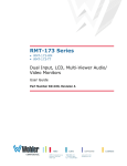
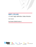
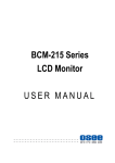
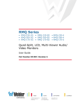
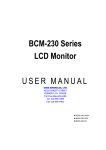
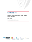
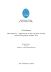
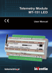
RMM1024 Monitor User Manual MODEL: RMM1024 Monitor VERSION: V010000 RELEASE DATE: 2013-12-20 Company Beijing Osee Digital Technology Ltd. Customer Support Address: No.22 Building, No.68 zone, Beiqing Road, Haidian District, Beijing, China Post Code: 100094 Tel: 010-62434168 Fax: 010-62434169 http://www.osee-dig.com/ E-mail: [email protected] About this manual Important The following symbols are used in this manual: The further information or know-how for described subjects above which helps user to understand them better. The safety matters or operations that user must pay attention to when using this product. Contents The user manual applies to the following device types: RMM1024-3HSV RMM1024-HSV RMM1024-SV The images of RMM1024-3HSV are adopted in the following descriptions. Any of the different specifications between the device types are elaborated. Before reading the manual, please confirm the device type. Contents Contents .......................................................................................................... I Chapter 1 Overview ....................................................................................... 1 Chapter 2 Safety............................................................................................. 3 Chapter 3 Unpack and Installation ............................................................... 5 Chapter 4 RMM1024 Features ....................................................................... 7 4.1 Front Panel Features .......................................................................... 8 4.1.1 Arrangement of Front Panel ............................................................. 9 4.1.2 Operation of Front Panel ................................................................ 10 4.2 Rear Panel Features .......................................................................... 15 4.2.1 Arrangement of Rear Panel ............................................................ 15 4.2.2 Operations of Rear Panel ............................................................... 16 4.3 Supported Signal Format ................................................................. 18 Chapter 5 Functionality of the Main Menu ................................................. 21 5.1 Main Menu ......................................................................................... 21 5.1.1 STATUS Menu ............................................................................... 24 5.1.2 INPUT SELECT Menu .................................................................... 26 5.1.3 MARKER Menu .............................................................................. 27 5.1.4 AUDIO Menu .................................................................................. 29 5.1.5 DISPLAY Menu .............................................................................. 31 5.1.6 CLOSE CAPTION Menu................................................................. 33 5.1.7 CONFIG Menu ................................................................................ 34 5.1.8 COLOR TEMP Menu ...................................................................... 38 5.1.9 FUNCTION KEY Menu ................................................................... 40 5.1.10 IMD Menu ..................................................................................... 41 5.2 Menu Settings.................................................................................... 43 Chapter 6 Network Control.......................................................................... 49 6.1 Access the settings........................................................................... 49 6.2 Menu Control ..................................................................................... 50 6.2.1 ADJUST Menu ................................................................................ 52 6.2.2 VIDEO DISPLAY Menu .................................................................. 54 6.2.3 SYSTEM Menu ............................................................................... 54 6.2.4 Other Menus ................................................................................... 55 6.3 Parameter Settings ........................................................................... 56 I Chapter 7 Specifications ............................................................................. 61 II Overview Chapter 1 Overview RMM1024 is a 10.1”, 2-screen, 4RU high full HD LCD monitor. It offers a full resolution 1920X1200 LCD panel, with wide viewing angle and wide color gamut. It supports the video signal of analog composite/3G/HD/SD-SDI and HDMI. It supports analog audio input/output. It supports precise color correction, audio meter display, wave form, vector and so on. It is compatible with the monitors of RMS series, and adding the new Ethernet function. Figure 1 A Diagram of RMM1024 Features Supports 3G/HD/SD-SDI, analog composite video signal and HDMI 1.3a Offers LCD panel with resolution of 1920 X1200, high-brightness, high-contrast and 178° wide viewing angle Supports color gamut modes that meet the criteria of SMPTE-C, EBU, ITU-709 Supports various color temperature(D93, D65, D56, D50, D32) and user customized color temperature Aluminum-magnesium alloy frame(with hanging board), standard 4RU high, adjustable frame 1 Overview Functionality Audio phase meter and phase alarm display 16 channels embedded audio level meter, the channel number and the dB value can be displayed Supports various markers: Center Marker, Area Marker and Safe Marker Supports TSL/IMAGE VIDEO dynamic TALLY protocol Supports TC code(VITC, LTC, D-VITC) Supports AFD prompts display Supports H/V Delay, NATIVE, BLUE ONLY, MONO Speaker and earphone output Supports Ethernet control 3G supports 1080P 50, 1080P 60 2 Safety Chapter 2 Safety Read, keep and follow all of these instructions for your safety. Heed all warnings. Monitor Do not beat with a hard object or scratch the LCD display. Do not make the freeze picture displaying on the screen time too long, otherwise, it will leave the afterimage on the screen. Install in accordance with the manufacturer's instructions. If the brightness is adjusted to the minimum, then it might be hard to see the display screen. Refer all servicing to qualified service personnel. Servicing will be required under all of the following conditions: The unit has been exposed to rain or moisture. Liquid had been spilled or objects have fallen onto the unit. The unit has been damaged in any way, such as when the power-supply cord or plug is damaged. The unit does not operate normally. Clean only with dry cloth. Specifications are subject to change without notice. Position Do not block any ventilation openings. Do not use this unit near water. 3 Safety Do not expose the unit to rain or moisture. Do not use this unit near any heat sources such as radiators, heat registers, stoves, or other apparatus (including amplifiers) that product heat. A nameplate indicating operating voltage, etc., is located on the rear panel. The socket-outlet shall be installed near the equipment and shall be easily accessible. Power Supply Cord Do not defeat the safety purpose of the polarized or grounding-type plug. Do not damage the power cord, place the heavy objects on the power cord, stretch the power cord, or bend the power cord. Protect the power cord from being walked on or pinched, particularly at plugs, convenience receptacles, and the point where they exit from the unit. If the power cord is damaged, turn off the power immediately. It is dangerous to use the unit with a damaged power cord. It may cause fire or electric shock. Unplug this unit during lighting storms or when unused for long periods of time. Disconnect the power cord from the AC outlet by grasping the plug, not by pulling the cord. Should any solid object or liquid fall into the cabinet, unplug the unit and have it checked by qualified personnel before operating it any further. 4 Unpack and Installation Chapter 3 Unpack and Installation Unpack: When unpacking the components of RMM1024 monitor, please verify that none of the components listed in Table 3.1 are damaged or lack. If there is any missing, contact your distributors or Beijing Osee Digital Technology Ltd. for it. Table 3.1 Packing List No. Item Quantity 1 Monitor 1 2 Power cord 1 3 adapter 1 4 User manual 1 5 warranty card 1 Installation: 1. Prepare for installation Please follow the procedures below before installing RMM1024 monitor: Check the equipment for any invisible damage that may have occurred during transit. Confirm all the items listed on the packing list have been received. Remove all the packing material including electrostatic-resistant packing. Retain these packing for future use. 2. Install RMM1024 in your desired location of a standard EIA equipment rack. Adequate ventilation is required when installed to prevent possible damage to the RMM1024internal components. 3. Connect required cables for signal input and output. For BNC connections use 75Ω rated connectors. 4. Connect AC power source using the included power cord. 5. Connect the power cord to the rear panel. 6. Fasten the power protect accessory. 7. As a final step, turn on each screen of the RMM1024 by pressing the corresponding power switch located on the front panel. 5 6 RMM1024 Features Chapter 4 RMM1024 Features This chapter describes the features of RMM1024 monitor. The features of RMM1024 monitor are as shown in Figure 4-1 after installed and powered on: Figure 4-1 Features of RMM1024 Monitor 1. Tally light: this LED light is at the top center of the front panel, and you can judge the monitor status by the color of Tally light. This tri-color (red/green/amber) light is controlled through a RJ45 connector on the rear panel. 2. Status Information: it is displayed in the top left corner of the screen, and includes the input channel and signal format. You can define it in DISPLAY menu. 3. Waveform and Vector: this is effective only for SDI signal. The waveform and vector of the input signal are configurable in the MAIN Menu. 4. Area Marker: it is used to mark different area of the image. You can set whether to display it or not and their displaying mode in MARKER menu. 5. Safe Marker: it is used to mark different area of the image. You can set whether to display it or not and their displaying mode in MARKER menu 7 RMM1024 Features 6. Center Marker: it is displayed in the center of the screen, and marks the center of the image. You can set whether to display it or not in MARKER menu. 7. Audio Meter: it is displayed for audio monitoring. You can set its groups, direction, position and mode in AUDIO menu. 8. Timecode: it is displayed at the bottom of the image, the format is HH:MM:SS:FF, if there is no timecode available, the monitor will display --:--:--:--. 9. IMD: the IMD text displays at the bottom of the screen, the length can’t exceed 16 characters, and you can choose letter, number or other character for it. 10. Headphone Interface: The Ω icon as shown in Screen No.1 is the headphone interface, it supports 3.5mm stereo, and the two screen share one headphone interface. The Status Information usually displays as the following situations: "UNKNOW” appears if an unsupported signal is input. “NO SIGNAL” appears if no signal is input. The signal is normal, for example: 1080i59.94, NTSC, 1280X1024, etc. The Status Information for the main picture displays at the top left corner of the screen, and the Status Information for the slave picture displays at the top right corner of the screen. The AFD information displays at the top center of the screen. 4.1 Front Panel Features It will introduce the arrangement and the operations of the buttons in front of the panel in the following. 8 RMM1024 Features 4.1.1 Arrangement of Front Panel There are a series of buttons at the bottom of the screen, and each group of buttons control the corresponding screen. IN 1 2 /MUTE MENU 3 Figure 4.1-1 4 F2 V V POWER F1 ENTER 5 6 7 the Buttons in Front Panel As shown in Figure 4.1-1, take the left screen of RMM1024 for example, these buttons are as follows: 1. Power 2. IN 3. /MUTE 4. MENU 5. F1/∨ 6. F2/∧ 7. ENTER Stand directly in front of a RMM1024, usually, the left screen is called No.1 screen, and the right screen is called No.2 screen. The buttons of Screen No.2 act as the same as the buttons of Screen No.1, and just effect on the current screen. This is the same to the usage of the interfaces in the rear panel, and no more repeat in the following contents. Only the POWER button and the AUDIO button have a light indicator. 9 RMM1024 Features 4.1.2 Operation of Front Panel The functionality and usage of the buttons at the front panel are as follows: 1. Power Used to power on or standby, and the light in the button will indicate the status of the power. If the light is green, the monitor is powered on, if the light is flashing, the monitor is standby. When the device is standby, cut off the power and restart the device, the status of the device will be normal but not standby. 2. IN Select the input signal. Press this button to display the source menu at the right top corner of the screen, as shown in Figure 4.1-2. Use it to select an input signal source, press it again to toggle among these input signal items. SOURCE SDI1 SDI2 LINE1(CVBS) LINE2(CVBS) HDMI Figure 4.1-2 Source Menu The one-to-one correspondence between the signals in the source menu list and the interfaces in the back panel are shown in Figure 4.1-3: 10 RMM1024 Features Figure 4.1-3 3. Correspondence between Source Menu and Interface /MUTE This button can achieve the following two functions: : Audio monitor button. Toggle this button to enable or disable the audio monitor, and the light in the button will indicate the status of audio monitoring. When the light is on, the audio is monitoring, and when the light is off, it is mute. The volume is adjusted in adjust menu. MUTE: Audio mute button. Toggle this button to enable or disable the audio monitor. Figure 4.1-4 Audio Monitor Menu 11 RMM1024 Features After you have loaded the Audio Monitor Menu, it will be closed automatically if you do nothing operation with it in 10s. 4. MENU It is used to activate the Main menu. Press this button to do some operations with the Main menu, it includes the following operations: Display the Main menu Back to the higher level menu Quit the Main menu Refer to “5.2 Menu Settings” for detail about the main menu operations. Press and hold the MUTE+ENTER button for 3s can reset the menu settings to factory originals, as shown in Figure 4.1-5. Figure 4.1-5 Reset Menu List 5. F1/∨ This button can achieve the following two functions: F1: F1 function button. Press F1 to display the function menu list in the center of the screen, as shown in Figure 4.1-6. Toggle F1 button to change the value related to this function. ∨: it is Down button when working with MENU. Toggle this button to select the next item or decrease the number. 12 RMM1024 Features Figure 4.1-6 Function Menu List After you have loaded the function menu list, it will be closed automatically if you do nothing operation with it in 10s. If the value related to the function button can’t be modified, the value shows in blue. Use FUNCTION KEY menu to assign F1 and F2. You can assign F1/F2 the function from among: SCAN, NATIVE, ASPECT, BLUE ONLY, MONO, MARKER, H/V DELAY, AUDIO METER, TC, IMD, UNDEF. Refer to "5.1.9 FUNCTION KEY Menu" for the details. 6. F2/∧ This button can achieve the following two functions: F2: F2 function button. Press F2 to display the function menu list in the center of the screen, toggle F2 button to change the value related to this function. ∧: it is Up button when working with MENU. Toggle this button to select the next item or increase the number. FUNCTION F1 MUTE OFF F2 NATIVE OFF Figure 4.1-7 Function Menu List 7. ENTER This button can achieve the following two situations: Work with the Main MENU: when working with the Main menu, 13 RMM1024 Features ENTER button achieve the following functions: Enter into the next level menu: press ENTER button, you will enter into the menu item as this relationship: the Main menu list sub-menu list sub-menu value list, the current editable object is in yellow control icon; Confirm the value selection: press ENTER button to confirm the value selection. Adjust Menu: when not displaying the Main menu, press ENTER button to display the adjust menu list, as shown in Figure 4.1-8, toggle among these menu items: VOLUME, BRIGHTNESS, CONTRAST, CHROMA. Figure 4.1-8 Adjust Menu List After displaying the Adjust menu, press ∧(Up) or ∨(Down) button to adjust the menu value, and then press ENTER button to confirm the value selection. The relationship of the menu items and their range is shown in Table 4.1-1: Table 4.1-1 The Description of Adjust Menu Items Adjust Menu Description Range Default VOLUME Adjust the volume 0~31dB 16 BRIGHTNESS Adjust the image brightness 0~100 50 CONTRAST Adjust the image contrast 0~100 50 CHROMA Adjust the image monochroma 0~100 50 Set these parameter value in the following position: BRIGHTNESS, CONTRAST, CHROMA. In Adjust Menu List on screen when pressing Enter key. In Adjust menu of network control page. 14 RMM1024 Features After you have loaded the adjust menu list, it will be closed automatically if you do nothing operation with it in 10s. The main menu, the adjust menu, the function menu and the input signal selection list of a screen may not be shown all simultaneously. 4.2 Rear Panel Features It will introduce the arrangement and the operations of the interfaces in rear of the panel in the following. 4.2.1 Arrangement of Rear Panel As shown in Figure 4.2-1, there are various input and output interfaces at the rear panel of RMM1024 monitor. Figure 4.2-1 The Rear Panel of RMM1024 Monitor The interfaces numbered from 1 to 8 in red dotted rectangle are described as follows: 1. Power Input 2. Video Input 3. Video Output 4. HDMI Input 5. Video Input 6. Audio Output 7. Audio Input 15 RMM1024 Features 8. Ethernet 9. RS485 In/Out 10. Tally Input 4.2.2 Operations of Rear Panel The details of these interfaces at the rear panel are described as follows: 1. Power Input It provides one power input interface, the specification is 5~12VDC. The corresponding indicator is at the front panel. If the light is green, the monitor is powered on, if the light is flashing, the monitor is standby, and if the light is off, the monitor is powered off. Only use the adapter and the power cord specified by the manufacture for your safety! 2. Video Input Interface (BNC) It provides two SDI input interfaces, one is labeled as SDI1 IN, and the other is SDI2 IN, 800mVp-p +/-10%. 3. Video Output Interface (BNC) It provides two SDI output interfaces. One is labeled as SDI1 OUT, the other is SDI2 OUT, 800mVp-p +/-10%, active loop. 4. HDMI It provides one HDMI input interface, HDMI Type-A connector with a fastener. 5. Video Input Interface (BNC) It provides two SDI input interfaces. One is labeled as LINE IN1, and the other is LINE IN2, 1Vp-p +/-3dB, sync negative. 6. Audio Output interface It provides two audio output interfaces, 5dBu, impedance≤500Ω, RCA connector. 7. Audio Input interface It provides four audio input interfaces, 5dBu, impedance≥47K, RCA connector. 16 RMM1024 Features 8. Ethernet (RJ-45) It provides one 10/100M Ethernet connector. It is used to connect with a computer to modify the network settings. 9. IN/ OUT RS485 Interface (RJ-45) Support for dynamic UMD and updating the new firmware. The Comparison of Pins and Input/output connectors for RS485 is shown as in Table 4.2-1: Table 4.2-1 The Comparison of Pins and Input/output connectors for RS485 PIN No. RS485 IN Terminal Signal RS485 OUT Terminal Signal 1,2 GND GND 3 Tx- Tx- 4 Rx+ Rx+ 5 Rx- Rx- 6 Tx+ Tx+ 7,8 NC NC 10. Tally(DB9) It controls the LED tally light. The relationship of the pins of Tally interface and its channel value is shown in Table 4.2-2. Table 4.2-2 The Relationship of Tally Input Pins and Channel Values Pin No. Channel Value Pin 1 CH1-R Pin 2 CH1-G Pin 3 CH2-R Pin 4 CH2-G Pin 8 GND 17 RMM1024 Features Thereinto, the tally light will display in different color according to its pin connection way, the relationship is shown in Table 4.2-2: Table 4.2-3 The Relationship of Tally Light Color and Pins Tally Light Screen 1 Color PIN1 Screen 2 PIN2 PIN3 PIN4 Red GND Open GND Open Green Open GND Open GND Amber GND GND GND GND Tally light is in working status when grounding. 4.3 Supported Signal Format The supported signal format for this device is as shown in Table 4.3-1: Table 4.3-1 Supported Signal Format SDI VIDEO PAL NTSC HDMI 480I60/59.94 576I50 480P60/59.94 576P50 720P24/23.97 720P25 720P30/29.97 720P50 720P60/59.94 1080SF24/23.97 1035I60/59.94 18 RMM1024 Features SDI VIDEO HDMI 1080I50 1080I60/59.94 1080P24/23.97 1080P25 1080P30/29.97 1080P50 1080P60/59.94 VGA(640X480) SVGA(800X600) XGA(1024X768) SXGA(1280X1024) WXGA(1360X768) WXGA+(1440X900) WXGA+(1400X1050) UXGA(1600X1200) UXGA+(1680X1050) WUXGA(1920X1080) WUXGA(1920X1200) 19 20 Functionality of the Main Menu Chapter 5 Functionality of the Main Menu This chapter describes the structure and functionality of the main menu, and introduces how to modify and customize the menu settings. The main menu includes the following menu items, as shown in Figure5-1. MAIN STATUS STATUS INPUT SELECT INPUT MARKER COLOR TEMP AUDIO SCAN MODE OVER DISPALY FAST MODE OFF CLOSE CAPTION MODEL CONFIG SERIAL NUMBER COLOR TEMP IP ADDRESS FUNCTION KEY COLOR VERSION SDI1 NO SIGNAL FORMAT D65 RM1024-3HSV RM10242013070001 192.168.1.86 65535 -255 -255.65535 IMD Figure 5-1 Main Menu 5.1 Main Menu Press the MENU button at the bottom of the front panel, the main menu is displayed at the top left corner of the screen, as shown in Figure 5.1-1: 1 MAIN 2 STATUS STATUS INPUT SELECT INPUT MARKER COLOR TEMP AUDIO SCAN MODE OVER DISPALY FAST MODE OFF CLOSE CAPTION MODEL CONFIG SERIAL NUMBER COLOR TEMP IP ADDRESS FUNCTION KEY COLOR VERSION FORMAT SDI1 NO SIGNAL D65 RM1024-3HSV RM10242013070001 192.168.1.86 65535 -255 -255.65535 IMD Figure 5.1-1 the Structure of the Main Menu 21 Functionality of the Main Menu The menu interface is divided into three parts: 1. Main Menu List: it contains the several sub-menu items. The title of this list is MAIN. Press Up(∧) or Down(∨) to access the corresponding menu item. 2. Sub-menu value list: as shown in Figure 5.1-2, it lists the control icon, sub-menu item and the value of the item. After pressing Menu button, press Up(∧), Down(∨) button and Enter button to modify the value of the sub-menu. Refer to “5.2 Menu Settings” for details. Figure 5.1-2 the Sub-menu Value List The sub-menu item is selected when the control icon which is in yellow highlight is at the back of the item name. The sub-menu item value is editable when the control icon which is in yellow highlight is at the back of the item value. The control icon of the main menu has the following status when in different positions, as shown in the red rectangle of the following figures: when in the main menu, it shows that this menu item is selected, as shown in Figure 5.1-3: 22 Functionality of the Main Menu Figure 5.1-3 A Main Menu Item Is Selected when in the sub-menu item, it shows that this sub-menu item is selected, and the control icon is displayed as a yellow rectangle in front of it, as shown in Figure 5.1-4: Figure 5.1-4 A Sub-menu Item Is Selected when in the sub-menu item value, it shows that this sub-menu item value is selected, and the value is displayed in yellow, as shown in Figure 5.1-5: 23 Functionality of the Main Menu Figure 5.1-5 A Sub-menu Item Value Is Selected The following will introduce the contents and functionality of these sub-menu items in sorts. 5.1.1 STATUS Menu The STATUS menu items are used to describe the current status information of the monitor, the menu items are as shown in Figure 5.1-6: Figure 5.1-6 STATUS Menu 24 Functionality of the Main Menu The relationship of Items, Default Value, Domain Range and Description of the sub-item is shown in Table 5.1-1: Table 5.1-1 Items The Description of STATUS Menu Items Default Value Domain Range INPUT SDI1 FORMAT NO SGINAL -- Show the format of the input signal COLOR TEMP D65 -- Show the temperature. SCAN MODE NORMAL FAST MODE OFF OFF/ON Show the fast mode. SD ASPECT 16:9 16:9/4:3 Show the screen Aspect Ratio. MODEL RMM1024-3HSV -- Show the production model. SERIAL NUMBER RMM10242013070001 -- Show the number. IP ADDRESS 192.168.1.86 -- Show the IP address. COLOR VERSION 2013-12-9.1 -- Show the color version according to its adjusted date. Description SDI1 SDI2 Show LINE1(CVBS) format LINE2(CVBS) HDMI NORMAL OVER UNDER the 25 color Show the scan mode. The sub-menu values in STATUS menu can’t be modified, they are displayed the actual status of the monitor. Input serial Functionality of the Main Menu 5.1.2 INPUT SELECT Menu The INPUT SELECT menu items are used to set the source of the input signals, the menu items are as shown in Figure 5.1-7: INPUT SELECT MAIN STATUS INPUT SELECT SDI1 ON SDI2 ON MARKER LINE1 ON AUDIO LINE2 ON DISPALY HDMI ON CLOSE CAPTION NTSC SETUP 7.5 CONFIG NTSC PHASE 0 COLOR TEMP FUNCTION KEY IMD Figure 5.1-7 INPUT SELECT Menu The relationship of Items, Default Value, Domain Range and Description of the sub-item is shown in Table 5.1-2: Table 5.1-2 The Description of INPUT SELECT Menu Items Items Default Value Domain Range Description SDI1 ON ON/OFF Enable/Disable SDI1 input SDI2 ON ON/OFF Enable/Disable SDI2 input LINE1 ON ON/OFF Enable/Disable LINE1 input LINE2 ON ON/OFF Enable/Disable LINE2 input HDMI ON ON/OFF Enable/Disable HDMI input NTSC SETUP 7.5 0/7.5 Select the NTSC mode NTSC PHASE 0 -50~50 Set the NTSC phase 26 Functionality of the Main Menu 5.1.3 MARKER Menu The MARKER menu items are used to adjust the marker parameters, the menu items are as shown in Figure 5.1-8: MARKER MAIN STATUS INPUT SELECT MARKER OFF AREA MARKER OFF MARKER CENTER MARKER OFF AUDIO SAFETY MARKER OFF DISPALY MARKER LEVEL CLOSE CAPTION MARKER MAT OFF CONFIG CROSS HATCH OFF 1 COLOR TEMP FUNCTION KEY IMD Figure 5.1-8 MARKER Menu The relationship of Items, Default Value, Domain Range and Description of the sub-item is shown in Table 5.1-3: Table 5.1-3 Items MARKER The Description of MARKER Menu Items Default Domain Range Value Description OFF Set whether to show all of the markers. It is the main switch for area marker, center marker and safety marker. AREA MARKER OFF OFF/ON when the 27 display Select the area marker Functionality of the Main Menu Items Default Domain Range Value Description aspect is 16:9, images aspect ratio according to show with the following the display aspect ratio. scale: OFF: close area marker 4:3 15:9 14:9 13:9 1.85:1 2.35:1 when the display aspect is 4:3, images show with the following scale: OFF: close area marker 16:9 CENTER MARKER SAFETY MARKER MARKER LEVEL MARKER MAT OFF OFF/ON Set whether to show the center marker OFF OFF 80% 85% 88% 90% 93% 95% Set the safety area size according to the aspect ratio and scan mode. 1 1: 50% 2: 75% 3: 100% Set the luminance of marker line, including safety marker, center marker, area marker and cross hatch. OFF: Normal background, use line for area marker edge only Set the transparency of area marker mat. HALF: 50% Background brightness BLACK: all black OFF CROSS HATCH OFF Set whether to show the cross hatch. OFF/ON 28 Functionality of the Main Menu The AREA MARKER, CENTER MARKER and SAFETY MARKER feature are available only when the MARKER item is set to ON. The marker will not display in PBP mode even if you have opened the marker switch. 5.1.4 AUDIO Menu The AUDIO menu items are used to adjust the audio parameters, the menu items are as shown in Figure 5.1-9: Figure 5.1-9 AUDIO Menu The relationship of Items, Default Value, Domain Range and Description of the sub-item is shown in Table 5.1-4: Table 5.1-4 Items AUDIO SOURCE Default Value EDB The Description of AUDIO Menu Items Domain Range EDB: embedded signal AUDIO1: external signal1 AUDIO2: external 29 Description Select the audio source. When there is no sync in and the input signal is not HDMI/SDI1/SDI2, Functionality of the Main Menu Items Default Value Domain Range signal2 UNDEF: no signal Description you can select only UNDEF, AUDIO1 or AUDIO2. EBD CH1 When the audio source is Left speaker, select a EBD, the range of this item channel according to the is EDB CH1~ EDB CH16. type of audio source. SPEAK OUT R EDB CH2 When the audio source is Right speaker, select a EBD, the range of this item channel according to the is EDB CH1~ EDB CH16. type of audio source. AUDIO METER OFF OFF/ON CH1-2 SPEAK OUT L METER SELECT METER VERTICAL DIRECTION METER POSITION BOT LEFT/ BOTTOM Set whether to display the audio meter. CH1-2 G1 G2 G3 G4 G1+G2 G1+G3 G1+G4 G2+G3 G2+G4 G3+G4 G1-G4 Select a meter display mode. Each G* contains four channels, and each CH* means a channel with number. VERTICAL HORIZONTAL Select the displayed direction of audio meter. When the value of METER DIRECTION is VERTICAL , you can choose the followings for Meter Position: BOT LEFT: bottom left BOT RIGHT: bottom right Select the displayed TOP RIGHT: top right position of audio meter. TOP LEFT: top left When the value of METER DIRECTION is HORIZONTAL, you can choose the followings for Meter Position: BOTTOM TOP 30 Functionality of the Main Menu Items Default Value Domain Range METER DIS MODE1 MODE MODE1: simple audio meter MODE2: audio meter with channel number MODE3: audio meter with channel number and dB value REF LEVEL -20dB -20dB/-18dB OVER LEVEL -10dB Description Select the displayed mode for audio meter. Select level -10dB -8dB -6dB -4dB -2dB the reference Select the overload level 5.1.5 DISPLAY Menu The DISPLAY menu items are used to adjust the parameters displayed on the screen, the menu items are as shown in Figure 5.1-10: Figure 5.1-10 DISPLAY SETUP Menu The relationship of Items, Default Value, Domain Range and Description of the sub-item is shown in Table 5.1-5: 31 Functionality of the Main Menu Table 5.1-5 Items STATUS DISPLAY AFD DISPLAY The Description of DISPLAY SETUP Menu Items Default Value Domain Range Description AUTO Set whether to display STD information. If the signal input is not equal to "No signal" and this item is auto, OFF/ON/AUTO the status information will show 15 seconds when the status changed, and then closed automatically. OFF OFF/ON NORMAL: Normal size Set the display size of WFM/VT. FULL: Full screen WFM FORM NORMAL SIZE WFM FORM NORMAL TYPE LINE WAVE OFF/ON OFF LINE WAVE 260 NUMBER Set whether to display AFD information. ON is an effective value to AFD DISPLAY item only if the value of STATUS DISPLAY is AUTO or ON. VECT100 VECT75 WAVE FORM Set whether to show line wave. As shown Table 5.1-6. WFM POS BOT RIGHT WFM OVERLIMIT 50 Switch the display mode among vector100, vector75 and wave form. in Set the position of WFM. BOT RIGHT BOT LEFT Select the displayed position for TOP LEFT WFM. BOT RIGHT 50~100 Set the over limit of WFM WFM 0 UNDERLIMIT 0~50 Set the under limit of WFM TIME CODE OFF OFF D-VITC LTC VITC Set whether to display TC, and select a mode for TC display. Thereinto, the value of LINE WFM is different according to the type of input signal, as shown in Table 5.1-6. 32 Functionality of the Main Menu Table 5.1-6 The Description for LINE WFM Item Input Signal Default Domain Range 576i50 310 23~623 480i60 261 22~524 720p 386 26~745 560 21~1123 1035i60 557 41~1120 1080p 561 42~1121 1080i50 1080i60/59.94 1080sf23/23.97 Only in PIP mode or PBP mode, you can call out the vectorscope or wave form, configure its size through DISPLAYWAVE FORM SIZE, configure its display mode through DISPLAYWAVE FORM TYPE, and configure its display position through CONFIGIMD POSITION. Use CONFIGSUB IN TYPE to switch to PIP mode or PBP mode. Refer to "5.1.7 CONFIG Menu" for details. Please refer to the international standard SMPTE2016-1-2007 for the details about AFD display. 5.1.6 CLOSE CAPTION Menu The CLOSE CAPTION menu items are used to adjust the parameters displayed on the screen, the menu items are as shown in Figure 5.1-10: 33 Functionality of the Main Menu MAIN CLOSE CAPTION STATUS INPUT SELECT CLOSED CAPTION CC1 SDI CC LOG OFF MARKER AUDIO DISPALY CLOSE CAPTION CONFIG COLOR TEMP FUNCTION KEY IMD Figure 5.1-11 CLOSE CAPTION Menu The relationship of Items, Default Value, Domain Range and Description of the sub-item is shown in Table 5.1-7: Table 5.1-7 Items CLOSE CAPTION The Description of CLOSE CAPTION Menu Items Default Value Domain Range OFF SDI CC LOG OFF CC1 CC2 CC3 CC4 TEXT1 TEXT2 TEXT3 TEXT4 OFF Description Set whether to display caption information, and select its display mode. Set whether to display CC information. OFF/ON 5.1.7 CONFIG Menu The CONFIG menu items are used to adjust the parameters defined by customers, the menu items are as shown in Figure 5.1-12: 34 Functionality of the Main Menu Figure 5.1-12 CONFIG Menu The relationship of Items, Default Value, Domain Range and Description of the sub-item is shown in Table 5.1-8: Table 5.1-8 The Description of CONFIG Menu Items Items Default Value Domain Range Description FAST MODE OFF OFF/ON Set whether mode. FILM DETECT OFF OFF/ON Set whether to detect film mode. PBP PBP/PIP/OFF Set the arrangement mode of screen picture SUB IN SELECT SDI1 PIP SIZE LARGE SMALL/LARGE MODE SUB IN TYPE SDI1 SDI2 LINE1(CVBS) LINE2(CVBS) HDMI WAVE FORM 35 in fast Set the source of slave picture, refer to Table 5.1-10 for the details. Set the size of PIP Functionality of the Main Menu Items Default Value Domain Range PIP POSITION BOT LEFT BACK LIGHT 15 BOT LEFT: bottom left BOT RIGHT: bottom right TOP RIGHT TOP LEFT Description Set the position of PIP 0~30 Adjust the back light AUTO STANDBY OFF OFF/ON Set whether open the standby mode. APPERTURE 0 0~24 Set the sharpness LOCK NUMBER XXXXXXXX -- Set the lock number LANGUAGE ENGLISH Select mode ENGLISH/CHINESE a picture language 1. PIP and PBP In PIP mode, the relationship of the main picture and the slave picture is as shown in Figure 5.1-13 : Figure 5.1-13 PIP Mode In PBP mode, the relationship of the main picture and the slave picture 36 Functionality of the Main Menu is as shown Figure 5.1-14: Figure 5.1-14 PBP Mode 2. Scope for the slave picture The selection scope of the signal source for the slave picture will be changing with the main picture's source, as shown in Table 5.1-9: Table 5.1-9 The Relationship of the Signal Source for Slave Picture and Main Picture Signal Source for Main Picture SDI1 SDI2 LINE1(CVBS) LINE2(CVBS) HDMI WFM \ Signal Source for Slave Picture SDI1 SDI2 LINE1(CVBS) LINE2(CVBS) HDMI In PIP mode, the WFM/Vector will be displayed as the slave picture; in PBP mode, the WFM/Vector will be displayed paralleled as the slave picture, as shown in Figure 5.1-15: 37 Functionality of the Main Menu Figure 5.1-15 The Slave Picture Is Displayed as WFM The length of LOCK NUMBER is up to 8 characters, you can use the combination of these characters: number (0 to 9) and letter (A to Z). Press ENTER to edit the LOCK NUMBER, than use ∧(Up) and ∨(Down) to select characters, than press ENTER to go to next character, press MENU to exit editor. 5.1.8 COLOR TEMP Menu The COLOR TEMP menu items are used to adjust the color temperature parameters and the color balance, the menu items are as shown in Figure 5.1-16: Figure 5.1-16 38 COLOR TEMP Menu Functionality of the Main Menu The relationship of Items, Default Value, Domain Range and Description of the sub-item is shown in Table 5.1-10: Table 5.1-10 Items The Description of COLOR TEMP Menu Items Default Value Domain Range Description USER1: Customized by user USER2: Customized by user D32: 3200K Set color temperature D50: 5000K D56: 5600K D65: 6500K D93: 9300K COLOR TEMP EDB RED GAIN 128 0~256 Adjust the Red Gain GREEN GAIN 128 0~256 Adjust the Green Gain BLUE GAIN 128 0~256 Adjust the Blue Gain RED BIAS 0 -50~50 Adjust the Red Offset GREEN BIAS 0 -50~50 Adjust the Green Offset BLUE BIAS 0 -50~50 Adjust the Blue Offset COPY FROM D65 D32: 3200K D50: 5000K D56: 5600K D65: 6500K D93: 9300K Copy this parameter value to USER RESET -- -- Reset the Gain and Offset values to the product originals COLOR SPACE EBU OFF/EBU/SMPTE-C/ ITU-709/AUTO Select the color matrix The items about RED/GREEN/BLUE GAIN and BIAS are available only in USER1 and USER2 mode. 39 Functionality of the Main Menu 5.1.9 FUNCTION KEY Menu The FUNCTION KEY menu items are used to define parameters to F1 and F2, the menu items are as shown in Figure 5.1-17: MAIN STATUS INPUT SELECT FUNCTION KEY F1 SCAN F2 OFF MARKER AUDIO DISPALY CLOSE CAPTION CONFIG COLOR TEMP FUNCTION KEY IMD Figure 5.1-17 FUNCTION KEY Menu The relationship of Items, Default Value, Domain Range and Description of the sub-item is shown in Table 5.1-11: Table 5.1-11 The Description of FUNCTION KEY Menu Items Items Default Value Domain Range Description F1 SCAN SCAN, NATIVE, ASPECT, BLUE ONLY, MONO, MARKER, H/V Set a function to DELAY, AUDIO METER, TC, F1 button IMD, UNDEF F2 SCAN the same as F1 SCAN This product supports the following scan modes: 40 Set a function to F2 button Functionality of the Main Menu NORMAL OVER UNDER Set the function button as [SCAN], press the button continuously to activate various scan modes. OVER: Zooms in/out of the image to 96% of its original size without changing the aspect ratio. NORMAL: Zooms in/out of the image without changing the aspect ratio. UNDER: Zooms in/out of the image without changing the aspect ratio. Also, displays the data at the top of the horizontal blanking block. ASPECT: Set the aspect ratio of the screen as 4:3 or 16:9. 5.1.10 IMD Menu The IMD menu items are used to adjust the parameters defined for IMD display, the menu items are as shown in Figure 5.1-18: Figure 5.1-18 IMD Menu The relationship of Items, Default Value, Domain Range and Description of the sub-item is shown in Table 5.1-12: 41 Functionality of the Main Menu Table 5.1-12 Items The Description of IMD Menu Items Default Value Domain Range Description IMD DISPLAY ON OFF/ON Set whether to display IMD CHARACTER on screen. IMD COLOR RED RED GREEN YELLOW WHITE Set the color for IMD CHARACTER. Set the IMD string displayed on the screen. After entering this item, press Up or Down to choose your character for this IMD string. IMD XXXXXXXX -CHARACTER LOCAL TSL3.1 TSL4.0 TSL5.0 IMAGE VIDEO NETWORK IMD PROTOCAL LOCAL IMD ID 000 0~255 IMD NAME XXXXXXXX BAUD RATE 38400 2400/4800/9600/19200 Select a baud rate for /38400/57600/115200 communication. LED TALLY ON OFF/ON OSD TALLY RG MODE Set the ID number for IMD Set an IMD name for each screen. IMD TALLY T1 MODE Select an IMD protocol Set whether to switch on tally light. RG: Red/Green GR: Green only RGY: Red/Green/Yellow OFF: No tally light Select the OSD Tally mode. Only the TALLY SOURCE is STANDARD or STANDARD + IV422, the setting is available. Select the IMD Tally mode. T1/T2/T1T2/T2T1/T1-/ Use this setting when T2-/T1T2-/T2T1using the Image Video tally control, this setting 42 Functionality of the Main Menu Default Value Items Domain Range Description will determine the state which is selected. TALLY SOURCE STANDARD STANDARD/IMAGE IDEO/TSL Select the source for LED tally source The length of IMD NAME and IMD CHARACTER is up to 16 characters. The character range is from 0x00 to 0x7F of ASCII. Press ENTER to edit the IMD characters, than use ∧(Up) and ∨(Down) to select characters, than press ENTER to go to next character, press MENU to exit editor. 5.2 Menu Settings When checking or modifying the value of the menu item, cooperating with the following buttons: MENU, ∧(Up), ∨(Down), ENTER. 1. Operations to the Main menu Display the Main Menu Press MENU button to enter into the main menu, it displays at the top left corner of the screen. Switch menu items After displaying the main menu, press ∧(Up) or ∨(Down) button to choose a menu item, the menu item selected is in yellow. For example, you have selected Status menu, as shown in Figure 5.2-1. 43 Functionality of the Main Menu MAIN STATUS STATUS INPUT SELECT INPUT MARKER COLOR TEMP AUDIO SCAN MODE OVER DISPALY FAST MODE OFF CLOSE CAPTION MODEL CONFIG SERIAL NUMBER COLOR TEMP IP ADDRESS FUNCTION KEY COLOR VERSION SDI1 FORMAT NO SIGNAL D65 RM1024-3HSV RM10242013070001 192.168.1.86 65535 -255 -255.65535 IMD Figure 5.2-1 Selecting STATUS Menu Back to the Main menu After entering to a sub-menu item or a sub-menu item value, press MENU button to back to the upper level menu area. Close the Main menu Press MENU button to close the Main menu when the control icon is in the Main menu item. After you have loaded the Main menu, it will be closed automatically if you do nothing operation with it in 60s. 2. Operations to sub-menu item Display the sub-menu item After display the Main menu, press ∧(Up) or ∨(Down) button to select a menu item, and the right part displays its sub-menu items according to the current selected menu item. Switch sub-menu items After displaying the sub-menu items list, press ENTER button to enter into the sub-menu items list, press ∧(Up) or ∨(Down) button to choose a sub-menu item, a yellow rectangle is in front of the selected sub-menu item. 44 Functionality of the Main Menu Back to menu item After entering to the sub-menu item value, press MENU button to back to menu items, or after setting the sub-menu item value and press Enter button to firm the modification, the control icon is back to the corresponding sub-menu item, as shown in Figure 5.2-2: INPUT SELECT SDI1 OFF INPUT SELECT SDI1 Figure 5.2-2 OFF The Control Icon Moves from the Sub-menu Item Value to the Corresponding Sub-menu Item 3. Operations to sub-menu item value Switch sub-menu item value When the control icon is in sub-menu item value, press ∧(Up) or ∨ (Down) button to switch among its value list. Confirm the modification to sub-menu item value Press ENTER button to confirm the selection of a value, and the control icon is back to the corresponding sub-menu item. Abandon the modification to sub-menu item value Press MENU button to give up the modification to sub-menu item value, and the control icon is back to the corresponding sub-menu item. The value in white color is modifiable, and the value in blue color is unmodifiable. 4. Selecting the Menu Language You can select one of languages (English or Chinese) for displaying the menu. The default language for the menu is ENGLISH. The following 45 Functionality of the Main Menu will teach you how to switch to Chinese. Operation: Step 1 Select CONFIG menu Press MENU button to display the OSD menu, click ∨(down) button to select CONFIG menu. Step 2 Select the value of the Language item Press ENTER button to get into the CONFIG menu items, and click ∨ (down) button to select the sub-item LANGUAGE, then, click ENTER button to get into the sub-value list, as shown in Figure 5.2-3, the current control icon is in ENGLISH. Figure 5.2-3 Select the Value of Language Step 3 Confirm the modification of the value of sub-item Click ∨(down) button to select the sub-item LANGUAGE to Chinese, as shown in Figure 5.2-4, press ENTER button to confirm the modification. 46 Functionality of the Main Menu Figure 5.2-4 Switching the Value of LANGUAGE Step 4 Exit the main menu Click MENU button to exit the main menu. 47 48 Network Control Chapter 6 Network Control RMM1024 supports network interface. Connect a computer with RMM1024 through this interface to achieve the network control to RMM1024. The network address of the computer which is connected with RMM1024 and the network address of RMM1024 must be in the same segment. This chapter will introduce how to set and check the parameters of RMM1024 in Internet Explorer. 6.1 Access the settings Use Internet Explorer to enter into a web control page. For example, input http://192.168.1.86 in address bar, it will display the then, press Enter key, the management interface of RMM1024 is shown as in Figure 6.1-1: Figure 6.1-1 Network Control Page 49 Network Control 6.2 Menu Control Open the management interface as shown in Figure 6.2-1, the menu items listed in the left part are almost as the same as the main menu items. Figure 6.2-1 Management Interface As shown in Figure 6.2-1, the management interface is divided into the following parts: 1. Screen selection button It is used to switch between the two screens at the top of the working area. Click “Monitor 1” to show the parameter values set in screen No.1, and click “Monitor 2” to show the parameter values set in screen No. 2. For a RMM1024 device, “Monitor 1” is corresponding to screen No.1, and “Monitor 2” is corresponding to screen No.2. Select a monitor before you set or check the parameters for it. 50 Network Control 2. Input Source Selection Button It is used to selecting an input source as the input signal, such as: SDI1, SDI2, LINE1, LINE2, HDMI. The selecting box of "Apply to All" at the right side is used to synchronize the settings of a monitor to another monitor. 3. Navigation menu list It shows the navigation menus: STATUS, ADJUST, VIDEO DISPLAY, INPUT SETUP, MARKER, AUDIO, DISPLAY, CLOSE CAPTION, USER CONFIG, COLOR TEMPERATURE, FUNCTION KEY, IMD and SYSTEM. Click the navigation menu, it will show the corresponding settings on the right side. The menu items in main menu on screen display are mostly as the same as the menu items listed in navigation menus except SYSTEM. 4. Parameter list It shows the parameter names, values and operation buttons of the selected navigation menu, as shown in the red rectangle in Figure 6.2-2. The title in the yellow rectangle of the parameter list and the parameter list will change with the navigation menu when switched. Figure 6.2-2 Parameter List 51 Network Control There may be a “(S)” icon followed by some parameter name in the parameter list, it is mean that this parameter is only a local parameter for the current selected monitor, otherwise, the parameter is global and the modification is valid for both screens. The SET button is used to confirm the modification of the parameter value. 6.2.1 ADJUST Menu It will introduce ADJUST menu. Click ADJUST button at the left navigation menu list, it will display the adjust parameters, as shown in Figure 6.2-5: Figure 6.2-3 ADJUST Menu 52 Network Control The relationship of Items, Default Value, Domain Range and Description of the sub-item is shown in Table 6.2-3: Table 6.2-1 The Description of ADJUST Menu Items Items Default Value Domain Range Description CONTRAST 50 0~100 Adjust contrast the picture BRIGHTNESS 50 0~100 Adjust the brightness picture CHROMA 50 0~100 Adjust the monochroma picture ASPECT 16:9 4:3/16:9 Set the aspect ratio of the picture BLUE ONLY NORMAL NORMAL/BLUE Enable/disable Only mode NORMAL NORMAL/MONO Enable/disable Monochrome mode, normal mode is actually the color mode H/V DELAY OFF MUTE Current Audio Level MONO FREEZE OFF Blue OFF H DELAY V DELAY H/V DELAY Display synchronizing signals in horizontal or vertical mode Current Audio Level MUTE Enable/disable the audio monitor OFF/ON Enable/disable the current picture to be stopped or played. WIN SOURCE MAIN MAIN/SUB Set the picture displaying mode in full mode or in sub-picture mode AUDIO MONITOR OFF OFF/ON Set whether in audio monitoring. VOLUME 15 0~31 Adjust the volume 53 Network Control 6.2.2 VIDEO DISPLAY Menu It will introduce VIDEO DISPLAY menu. Click VIDEO DISPLAY button at the left navigation menu list, it will display the video display parameters, as shown in Figure 6.2-5: Figure 6.2-4 VIDEO DISPLAY Menu The relationship of Items, Default Value, Domain Range and Description of the sub-item is shown in Table 6.2-3: Table 6.2-2 The Description of VIDEO DISPLAY Menu Items Items Default Value Domain Range SCAN NORMAL NATIVE OFF OFF/ON NORMAL OVERSCAN UNDERSCAN Description Set the scan mode Whether to display the picture dot by dot 6.2.3 SYSTEM Menu It will introduce SYSTEM menu. Click SYSTEM button at the left navigation menu list, it will display the system parameters, as shown in Figure 6.2-5: 54 Network Control Figure 6.2-5 System Menu The relationship of Items, Default Value, Domain Range and Description of the sub-item is shown in Table 6.2-3: Table 6.2-3 The Description of System Menu Items Items Default Value Domain Range Description IP 192.168.1.86 - IP address MASK 255.255.255.0 - Subnet mask Gateway 192.168.1.1 - Gateway address LOCK NUMBER 0001 - Serial Number 32626 Version 3 - Product information FPGA Version 1 - Product information F107 Version 1 - Product information 6.2.4 Other Menus For the menu items in management interface are almost as the same as 55 Network Control the menu items in the Main menu on screen, there will be no further description about their meanings and value range in this chapter, refer to “Chapter 5 Functionality of the Main Menu” for the details about STATUS, VIDEO CONFIG, AUDIO CONFIG, MARKER, DISPLAY, USER CONFIG, and COLOR TEMPERATURE. 6.3 Parameter Settings It will introduce how to modify parameter values in management interface in the followings. For example: modify Meter Select in AUDIO menu. Click AUDIO button to display its parameter list, as shown in Figure 6.3-1, the corresponding screen main menu is shown as in Figure 6.3-2: Figure 6.3-1 Parameter List for AUDIO 56 Network Control Figure 6.3-2 Screen Main Menu for AUDIO button to display the drop-down value list for the parameter, as shown Click in Figure 6.3-3, for example, modify “CH1-2” to “G1”. Figure 6.3-3 Display the Drop Down Value List of Meter Select(S) 57 Network Control Click button to confirm the selection and the page is refreshed. You can check the modification on the screen menu, the results are the same as shown in Figure 6.3-4 and Figure 6.3-5: Figure 6.3-4 Modify the Value of a Parameter The volume can be checked and modified in adjust menu on screen adjustment, or in Volume item of ADJUST menu in management interface. 58 Network Control Figure 6.3-5 The Value is Modified Simultaneously on Screen Menu Likewise, if you modify the value of a parameter on screen menu first, you may check the same changing result in management interface through network connection. 59 60 Specifications Chapter 7 Specifications 1. Product detailed information Specification Values Number of Screens 2 Aspect Ratio 16:10 Display Area(mm) 216.81(H)×135.50(V) Viewing Angle 178°(H)x178°(V) Color Depth 16.7M colors (RGB 8-bits) Resolution 1920(H)×1200(V) Dot Pitch(mm) 0.113(H)×0.113(V) Contrast 800:1 Brightness(cd/㎡) 400 typ. (5 points average) 340 min. (5 points average) Response Time (ms Typ.) <25 Backlight WhiteLED Backlight Life(Hrs) 20000 Work Temperature 0°C~35°C SD: 480ip59.94, 576i50 HD: SMPTE-274M: 1080i 50/59.94,1080p/PsF 23.98/24/25 Signal Formats HD: SMPTE-296M: 720p 50/59.94 3G: SMPTE-425 level A(mapping 1): 1080p 50/59.94 HDMI 1.3a Compliant to EIA/CEA-861-D 3G/HD/SD-SDI Input(75Ohm BNCx2) Input Analog Composite (75Ohm BNCx2) HDMI Input(HDMI Type A) Analog stereo input(RCAx4) Output 3G/HD/SD-SDI Input(BNCx2) Analog stereo output (RCAx2) 61 Specifications Specification Values Stereo HEADPHONE (3.5mm stereo Jack) 2. Dimensions The description of the product dimensions of RMM1024is shown as in the following figures: Figure 7-1 Front Panel(Unit: mm) Figure 7-2 Rear Panel(Unit: mm) 62 Specifications Figure 7-3 Side View(Unit: mm) Specifications are subject to change without notice. ------------------No Text Below------------------ 63 FOR MORE INFORMATION PLEASE VISIT: http://www.osee-dig.com/ No.22 Building, No.68 zone, Beiqing Road, Haidian District, Beijing, China Tel: (+86) 010-62434168, Fax: (+86) 010-62434169 E-mail: [email protected]