1
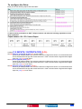
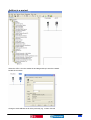
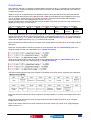
In Menu [1.9 COMMUNICATION] (COM-)
Set [Scan. Out1 address] (nCA1) to 8601
This configures the IO scanner to direct bytes 0 and 1 to address 8601 which is the drive command
word. (CMd)
Set [Scan. Out2 address] (nCA2) to 8602
This configures the IO scanner to direct bytes 2 and 3 to address 8602 which is the drive speed
reference. (LFRD)
Set [Scan. Out3 address] (nCA3) to 9001
This configures the IO scanner to direct bytes 4 and 5 to address 9001 which is the drive
acceleration rate. (ACC)
Set [Scan. Out4 address] (nCA4) to 9002
This configures the IO scanner to direct bytes 6 and 7 to address 9002 which is the drive
deceleration rate. (dEC)
[Scan. Out5 address] (nCA5) to [Scan. Out8 address] (nCA8) are not useful for the DeviceNet card.
Set [Scan. In1 address] (nMA1) to 8603
This configures the drive to direct the value held in address 8603 which is the drive status word
(EtA) to bytes 0 and 1 of the IO scanner.
Set [Scan. In2 address] (nMA2) to 8604
This configures the drive to direct the value held in address 8604 which is the drive output speed
(rFrd) to bytes 2 and 3 of the IO scanner.
Set [Scan. In3 address] (nMA3) to 9630
This configures the drive to direct the value held in address 9630 which is the motor thermal state
(tHd) to bytes 4 and 5 of the IO scanner.
Set [Scan. In4 address] (nMA4) to 3204
This configures the drive to direct the value held in address 3204 which is the motor current (LCr) to
bytes 6 and 7 of the IO scanner.
[Scan. In5 address] (nCA5) to [Scan. In8 address] (nCA8) are not useful for the DeviceNet card.
Schneider Electric
7