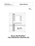
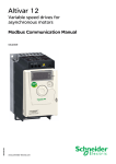
1
Altivar 71
User's manual
Retain for future use
Modbus Plus card
VW3 A3 302
Contents
1. Before you begin___________________________________________________________________________________________ 3
2. Documentation structure_____________________________________________________________________________________ 4
3. Introduction _______________________________________________________________________________________________ 5
3. 1. Presentation _________________________________________________________________________________________ 5
3. 2. Notation ____________________________________________________________________________________________ 5
4. Hardware setup ___________________________________________________________________________________________
4. 1. Receipt _____________________________________________________________________________________________
4. 2. Hardware description __________________________________________________________________________________
4. 3. Installing the card in the drive ____________________________________________________________________________
4. 4. Configuring the switches________________________________________________________________________________
6
6
6
6
7
5. Connecting to the network ___________________________________________________________________________________
5. 1. Connector pinout _____________________________________________________________________________________
5. 2. Connection accessories ________________________________________________________________________________
5. 3. Modbus Plus wiring system _____________________________________________________________________________
8
8
8
9
6. Modbus Plus menu ________________________________________________________________________________________
6. 1. Access via graphic display terminal ______________________________________________________________________
6. 2. Access via the integrated display terminal _________________________________________________________________
6. 3. Modbus Plus parameters ______________________________________________________________________________
11
11
11
12
7. Configuration ____________________________________________________________________________________________
7. 1. Communication parameters ____________________________________________________________________________
7. 2. Control - Signaling ___________________________________________________________________________________
7. 3. Communication scanner _______________________________________________________________________________
7. 4. Communication faults _________________________________________________________________________________
7. 5. Monitored parameters_________________________________________________________________________________
13
13
14
17
19
20
8. Diagnostics ______________________________________________________________________________________________
8. 1. Checking the address _________________________________________________________________________________
8. 2. LEDs ______________________________________________________________________________________________
8. 3. Control - Signaling ___________________________________________________________________________________
8. 4. Communication scanner _______________________________________________________________________________
8. 5. Communication fault __________________________________________________________________________________
8. 6. Card fault __________________________________________________________________________________________
21
21
21
22
23
24
24
While every precaution has been taken in the preparation of this document,
Schneider Electric SA assumes no liability for any omissions or errors it may contain,
nor for any damages resulting from the application or use of the information herein.
The products and options described in this document may be changed or modified at
any time, either from a technical point of view or in the way they are operated. Their
description can in no way be considered contractual.
2
1. Before you begin
Read and understand these instructions before performing any procedure with this drive.
DANGER
HAZARDOUS VOLTAGE
• Read and understand the Installation Manual before installing or operating the Altivar 71 drive. Installation, adjustment,
repair, and maintenance must be performed by qualified personnel.
• The user is responsible for compliance with all international and national electrical standards in force concerning
protective grounding of all equipment.
• Many parts of this variable speed drive, including the printed circuit boards, operate at the line voltage. DO NOT TOUCH.
Use only electrically insulated tools.
• DO NOT touch unshielded components or terminal strip screw connections with voltage present.
• DO NOT short across terminals PA and PC or across the DC bus capacitors.
• Install and close all the covers before applying power or starting and stopping the drive.
• Before servicing the variable speed drive
- Disconnect all power.
- Place a “DO NOT TURN ON” label on the variable speed drive disconnect.
- Lock the disconnect in the open position.
• Disconnect all power including external control power that may be present before servicing the drive. WAIT 15
MINUTES to allow the DC bus capacitors to discharge. Then follow the DC bus voltage measurement procedure given
in the Installation Manual to verify that the DC voltage is less than 45 VDC. The drive LEDs are not accurate indicators
of the absence of DC bus voltage.
Electric shock will result in death or serious injury.
CAUTION
DAMAGED EQUIPMENT
Do not install or operate any drive that appears damaged.
Failure to follow this instruction can result in equipment damage.
3
2. Documentation structure
The following Altivar 71 technical documents are available on the Web site www.telemecanique.com and on the CDROM delivered with
each drive.
b Installation Manual
This manual describes:
• How to assemble the drive
• How to connect the drive
b Programming Manual
This manual describes:
• The functions
• The parameters
• How to use the drive display terminal (integrated display terminal and graphic display terminal)
b Communication Parameters Manual
This manual describes:
• The drive parameters with specific information (addresses, formats, etc.) for use via a bus or communication network
• The operating modes specific to communication (state chart)
• The interaction between communication and local control
b Modbus, CANopen, Ethernet, Profibus, INTERBUS, Uni-Telway, DeviceNet, Modbus Plus, Fipio,
etc., manuals
These manuals describe:
• Connection to the bus or network
• Configuration of the communication-specific parameters via the integrated display terminal or the graphic display terminal
• Diagnostics
• Software setup
• The communication services specific to the protocol
b Altivar 58/58F Migration Manual
This manual describes the differences between the Altivar 71 and the Altivar 58/58F.
It explains how to replace an Altivar 58 or 58F, including how to replace drives communicating on a bus or network.
4
3. Introduction
3. 1. Presentation
The Modbus Plus communication card (catalog number VW3 A3 302) is used to connect an Altivar 71 drive to a Modbus Plus network.
The data exchanges permit full drive functionality:
• PeerCop control and adjustment
• Monitoring using the Global Data service
• Configuration, adjustment and diagnostics using the Modbus message handling service
If the Peer Cop service is not used for control, the drive can be controlled using the Modbus message handling service.
The card has a 9-way female SUB-D connector for connection to the Modbus Plus network.
The address of the drive is configured using the switches on the card.
The graphic display terminal on the drive can be used to access numerous functions for communication diagnostics.
The cable and accessories for connection to the Modbus Plus network must be ordered separately.
3. 2. Notation
Drive terminal displays
The graphic display terminal menus are shown in square brackets.
Example: [1.9 COMMUNICATION].
The integrated 7-segment display terminal menus are shown in round brackets.
Example: (COM-).
Parameter names are displayed on the graphic display terminal in square brackets.
Example: [Fallback speed]
Parameter codes are displayed on the integrated 7-segment display terminal in round brackets.
Example: (LFF).
Formats
In this manual:
- Hexadecimal values are written as follows: 16#
- Binary values are written as follows: 2#
5
4. Hardware setup
4. 1. Receipt
Check that the card catalog number marked on the label is the same as that on the delivery note corresponding to the purchase order.
Remove the option card from its packaging and check that it has not been damaged in transit.
4. 2. Hardware description
Green LED
9-way female SUB-D connector
8 addressing switches, also used to select the
mode (normal or ATV58/58F migration)
4. 3. Installing the card in the drive
See the Installation Manual.
6
4. Hardware setup
4. 4. Configuring the switches
The switches are used to configure the mode (normal or Altivar 58/58F migration) and the address on the network.
The correspondence between the drive and the position of the switch is as follows:
• 0 = OFF = Switch in upper position
• 1 = ON = Switch in lower position
The switch on the right-hand side is used to configure the Modbus Plus card mode:
• 0 = OFF = normal mode
• 1 = ON = Altivar 58/58F migration mode
This manual only describes normal mode.
To find out about Altivar 58 migration mode, refer to the Altivar 58/58F Migration Manual.
The table below indicates the positions of the switches for all configurable addresses (1 to 64) in normal mode:
Address
1
2
3
4
5
6
7
8
9
10
11
12
13
14
15
16
Switches
0000 0000
1000 0000
0100 0000
1100 0000
0010 0000
1010 0000
0110 0000
1110 0000
0001 0000
1001 0000
0101 0000
1101 0000
0011 0000
1011 0000
0111 0000
1111 0000
Address
17
18
19
20
21
22
23
24
25
26
27
28
29
30
31
32
Switches
0000 1000
1000 1000
0100 1000
1100 1000
0010 1000
1010 1000
0110 1000
1110 1000
0001 1000
1001 1000
0101 1000
1101 1000
0011 1000
1011 1000
0111 1000
1111 1000
Address
33
34
35
36
37
38
39
40
41
42
43
44
45
46
47
48
Switches
0000 0100
1000 0100
0100 0100
1100 0100
0010 0100
1010 0100
0110 0100
1110 0100
0001 0100
1001 0100
0101 0100
1101 0100
0011 0100
1011 0100
0111 0100
1111 0100
Address
49
50
51
52
53
54
55
56
57
58
59
60
61
62
63
64
Switches
0000 1100
1000 1100
0100 1100
1100 1100
0010 1100
1010 1100
0110 1100
1110 1100
0001 1100
1001 1100
0101 1100
1101 1100
0011 1100
1011 1100
0111 1100
1111 1100
Examples:
Address 10
Address 23
7
5. Connecting to the network
5. 1. Connector pinout
Contact 1
shield
Contact 2
signal
Contact 3
signal
9-way female SUB-D connector
5. 2. Connection accessories
Modbus Plus card VW3 A3 302
9-way female
SUB-D connector on card
Modbus Plus 990 NAD 219pp drop cable
(2, 4 or 6 m)
Modbus Plus 490 NAA 271pp trunk cable
Modbus Plus tap
990 NAD 230 00
8
5. Connecting to the network
5. 3. Modbus Plus wiring system
Quantum
10
Network # 2
Premium
11
8
10
4
10
11
5
Network # 1
11
2
12
6
6
11
13
7
1
1
RS 485
3
9
Fiber-optic link
RS 232
ATV 38
ATV 71
13
ATS 48
13
ATV 31
Quantum
b Cards and gateways
Description
Used with
ATV 38
ATV 71
ATS 48, ATV 31
Reference
number
1
1
2
Communication cards
VW3 A58 302
VW3 A3 302
NW BM85000
ATS 48, ATV 31
3
XGS Z24
Description
Used with
Modbus Plus tap
(IP 20)
Modbus Plus in-line connector
Connector with Modbus Plus terminator
(sold in lots of 2)
Modbus Plus electrical repeater
extension for 64 subscribers
Modbus Plus bridge with 4 ports
Line/station fiber-optic repeater
Point-to-point fiber-optic repeater
For connecting via a tap junction
Reference Catalog number
number
4
990 NAD 230 00
Gateway, bridge and repeater
Bridge and repeater
5
6
AS MBKT 085
AS MBKT 185
Extension beyond 450 m
7
NW RR85 001
Connection of 4 networks maximum
–
Used to connect an electrical segment to the fiberoptic segment (3000 m maximum)
Mounting trunk and drop cables in a 990 NAD 230 00
tap
8
9
_
NW BP85 002
490 NRP 254 00
NW NRP 253 00
–
043 509 383
Modbus Plus/Modbus
Gateway
4 x RS 232 ports
115Ö220 V a power supply
RS 232/RS 485 interface
24 V c, 20 mA power supply (1)
Catalog number
b Connection accessories
Wiring tool
(1) Please consult our specialist “Interfaces, I/O splitter boxes and power supplies” catalog.
9
5. Connecting to the network
b Cables
Description
Modbus Plus
trunk cables
Drop cables
1 x 9-way female
SUB-D connector
and
1 x stripped end
Used with
From
Modbus Plus tap
990 NAD 230 00
ATV 38 (+ VW3 A58 302
communication card), Premium/
Quantum PLCs, NW BP85 002
Modbus Plus bridge with 4 ports,
490 NRP 253 00 line/station
fiber-optic repeater
ATV 71 (+ VW3 A3 302
communication card)
Cable for Modbus
ATS 48, ATV 31, NW BM85000
1 x RJ45 contact and Modbus Plus/Modbus gateway
1 x stripped end
To
Modbus Plus tap
990 NAD 230 00, Modbus Plus
in-line connector AS MBKT 085,
connector with Modbus Plus
terminator AS MBKT 185
Reference Length Catalog number
number
m
10
Modbus Plus tap
990 NAD 230 00
11
Modbus Plus tap
990 NAD 230 00
12
RS 232/RS 485 interface
13
30.5
152.5
305
457
1525
2.4
6
490 NAA 271 01
490 NAA 271 02
490 NAA 271 03
490 NAA 271 04
490 NAA 271 06
990 NAD 211 10
990 NAD 211 30
2.4
6
3
990 NAD 219 10
990 NAD 219 30
VW3 A8 306 D30
To order other connection elements, please consult our specialist "Automation platform Modicon Premium and Unity - PL7 software" and
"Automation platform Modicon Quantum" catalogs.
10
6. Modbus Plus menu
6. 1. Access via graphic display terminal
The [MODBUS PLUS] submenu is used to configure and display the parameters of the Modbus Plus card and can be accessed via the
[1.9 - COMMUNICATION] menu.
RDY
RDY
Term +0.00Hz
MAIN MENU
1 DRIVE MENU
2 CONTROL ACCESS
3 OPEN / SAVE AS
4 PASSWORD
5 LANGUAGE
Code
0A
ENT
Quick
Term +0.00Hz
0A
1 DRIVE MENU
1.1 SIMPLY START
1.2 MONITORING
1.3 SETTINGS
1.4 MOTOR CONTROL
1.5 INPUTS/OUTPUTS CFG
Code
<<
>>
Quick
1.6 COMMAND
1.7 APPLICATION FUNCT.
1.8 FAULT MANAGEMENT
1.9 COMMUNICATION
1.10 DIAGNOSTICS
1.11 IDENTIFICATION
1.12 FACTORY SETTINGS
1.13 USER MENU
1.14 PROGRAMMABLE CARD
RUN
ENT
Term
+50.00Hz 80A
1.9 COMMUNICATION
COM. SCANNER OUTPUT
MODBUS HMI
MODBUS NETWORK
CANopen
MODBUS PLUS
Code
<<
>>
Quick
6. 2. Access via the integrated display terminal
The (MbP-) submenu is used to configure and display the Modbus Plus card parameters and can be accessed via the (COM-) menu.
Power-up
XXX
Displays the drive status
ENT
ESC
SIM-
ESC
FLtENT
ESC
COMMUNICATION
CONESC
ESC
FCS-
ESC
LAC-
11
6. Modbus Plus menu
6. 3. Modbus Plus parameters
Code
(AdrC)
Description
M [Address]
Modbus Plus address
Type:
Display (read-only)
Possible values:
1 ... 64
This parameter can be used solely to read back the value coded on the switches on the Modbus Plus card.
(tLP)
M [Network time out]
Communication monitoring time out
Type:
Configuration (read and write)
Possible values:
0.1 ... 60 s
Default value:
10 s
Unit:
0.1 s
The value of this parameter must be greater than:
• The maximum time that elapses without a token being received
• The maximum time between two Peer Cop receptions
(PrC)
M [Peer Cop]
Enable Peer Cop service
Type:
Configuration (read and write)
Possible values:
• [No] (nO)
: Peer Cop service disabled
• [Yes] (YES)
: Peer Cop service enabled
Default value:
[No] (nO)
(rEG)
M [Number of registers]
Number of registers for the Peer Cop service
Type:
Configuration (read and write)
Possible values:
0 ... 32
In normal mode, values between 9 and 32 are meaningless.
Default value:
(GLb)
M [Global Tx]
Number of registers for the Global Data service
Type:
Configuration (read and write)
Possible values:
0 ... 32
In normal mode, values between 9 and 32 are meaningless.
Default value:
(Cdn)
0
M [Command station]
Address of the Modbus Plus station authorized to control the drive
Type:
Configuration (read and write)
Possible values:
• 0: The drive will ignore Peer Cop services.
• 1 ... 64: Address of the Modbus Plus station authorized to control the drive using Peer Cop.
Default value:
12
0
0
7. Configuration
7. 1. Communication parameters
b Peer Cop
Peer Cop parameters are used as periodic output variables on the PLC controlling the drive.
To configure Peer Cop parameters, you must first know the number of periodic control and adjustment variables required for the application
(maximum: 8).
Configure the following parameters in the [1.9 - COMMUNICATION] (COM-) menu, [MODBUS PLUS] (MbP-) submenu:
[Peer Cop] (PrC)
[Number of registers] (rEG)
[Command station] (Cdn)
: [Yes] (YES)
: Number of Peer Cop control and adjustment variables
: PLC's Modbus Plus address
If only the drive is monitored, [Peer Cop] (PrC) will be set to the factory value [No] (nO).
b Global Data
Global Data parameters are used as periodic input variables on the PLC controlling the drive.
To configure Global Data parameters, you must first know the number of periodic monitoring variables required for the application
(maximum: 8).
Configure the following parameters in the [1.9 - COMMUNICATION] (COM-) menu, [MODBUS PLUS] (MbP-) submenu:
[Global Tx] (GLb)
: Number of Global Data monitoring variables
Note: These configurations are taken into account immediately by the drive (the power supply does not have to be disconnected).
13
7. Configuration
7. 2. Control - Signaling
Numerous configurations are possible. For more information, refer to the Programming Manual and the Parameters Manual.
The following configurations are just some of the possibilities available.
b Control via Modbus Plus in I/O profile
The command and reference come from Modbus Plus.
The command is in I/O profile.
Configure the following parameters:
Parameter
Value
Comment
Profile
I/O profile
The run command is obtained simply by bit 0 of the control word.
Reference 1 configuration
Network card The reference comes from Modbus Plus.
Command 1 configuration
Network card The command comes from Modbus Plus.
Configuration via the graphic display terminal or the integrated display terminal:
Menu
[1.6 - COMMAND] (CtL-)
Parameter
Value
[Profile] (CHCF)
[I/O profile] (IO)
[Ref.1 channel] (Fr1)
[Com. card] (nEt)
[Cmd channel 1] (Cd1)
[Com. opt card] (nEt)
b Control via Modbus Plus or the terminals in I/O profile
Both the command and reference come from Modbus Plus or the terminals. Input LI5 at the terminals is used to switch between
Modbus Plus and the terminals.
The command is in I/O profile.
Configure the following parameters:
Parameter
Value
Comment
Profile
I/O profile
The run command is obtained simply by bit 0 of the control word.
Reference 1 configuration
Network card
Reference 1 comes from Modbus Plus.
Reference 1B configuration
Analog input 1 on the terminals Reference 1B comes from input AI1 on the terminals.
Reference switching
Input LI5
Input LI5 switches the reference (1 ↔1B).
Command 1 configuration
Network card
Command 1 comes from Modbus Plus.
Command 2 configuration
Terminals
Command 2 comes from the terminals.
Command switching
Input LI5
Input LI5 switches the command.
Note: Target 1B is connected to the functions (Summing, PID, etc) which remain active even after switching.
Configuration via the graphic display terminal or the integrated display terminal:
Menu
Parameter
Value
[1.6 - COMMAND] (CtL-)
[Profile] (CHCF)
[I/O profile] (IO)
[Ref.1 channel] (Fr1)
[Com. card] (nEt)
[Cmd channel 1] (Cd1)
[Com. card] (nEt)
[Cmd channel 2] (Cd2)
[Terminals] (tEr)
[1.7 APPLICATION FUNCT.] (FUn-)
[REFERENCE SWITCH.]
14
[Cmd switching] (CCS)
[LI5] (LI5)
[Ref.1B channel] (Fr1b)
[Ref. AI1] (AI1)
[Ref 1B switching] (rCb)
[LI5] (LI5)
7. Configuration
b Control via Modbus Plus in Drivecom profile
The command and reference come from Modbus Plus.
The command is in Drivecom profile.
Configure the following parameters:
Parameter
Value
Comment
Profile
Drivecom profile not
separate
The run commands are in Drivecom profile, the command and the reference
come from the same channel.
Reference 1 configuration
Network card
The command comes from Modbus Plus.
Configuration via the graphic display terminal or the integrated display terminal:
Menu
Parameter
Value
[1.6 - COMMAND] (CtL-)
[Profile] (CHCF)
[Not separ.] (SIM) (factory setting)
[Ref.1 channel] (Fr1)
[Com. card] (nEt)
b Control via Modbus Plus or the terminals in Drivecom profile
Both the command and reference come from Modbus Plus or the terminals. Input LI5 at the terminals is used to switch between
Modbus Plus and the terminals.
The command is in Drivecom profile.
Configure the following parameters:
Parameter
Value
Comment
Profile
Drivecom profile not separate
The run commands are in Drivecom profile, the command and the
reference come from the same channel.
Reference 1 configuration
Network card
Reference 1 comes from Modbus Plus.
Reference 2 configuration
Analog input 1 on the terminals
Reference 2 comes from input AI1 on the terminals.
Reference switching
Input LI5
Input LI5 switches the reference (1 ↔ 2) and the command.
Note: Reference 2 is directly connected to the drive reference limit. If switching is performed, the functions that affect the reference
(summing, PID, etc.) are inhibited.
Configuration via the graphic display terminal or the integrated display terminal:
Menu
Parameter
Value
[1.6 - COMMAND] (CtL-)
[Profile] (CHCF)
[Not separ.] (SIM)
[Ref.1 channel] (Fr1)
[Com. card] (nEt)
[Ref.2 chan] (Fr2)
[Ref. AI1] (AI1)
[Ref. 2 switching] (rFC)
[LI5] (LI5)
15
7. Configuration
b Control in Drivecom profile via Modbus Plus and reference switching at the terminals
The command comes from Modbus.
The reference comes either from Modbus Plus or from the terminals. Input LI5 at the terminals is used to switch the reference between
Modbus Plus and the terminals.
The command is in Drivecom profile.
Configure the following parameters:
Parameter
Value
Comment
Profile
Drivecom profile separate
The run commands are in Drivecom profile, the command and the
reference can come from different channels.
Reference 1 configuration
Network card
Reference 1 comes from Modbus Plus.
Reference 1B configuration
Analog input 1 on the terminals
Reference 1B comes from input AI1 on the terminals.
Reference switching
Input LI5
Input LI5 switches the reference (1 ↔1B).
Command 1 configuration
Network card
Command 1 comes from Modbus Plus.
Command switching
Channel 1
Channel 1 is the command channel.
Note: Target 1B is connected to the functions (Summing, PID, etc) which remain active even after switching.
Configuration via the graphic display terminal or the integrated display terminal:
Menu
Parameter
Value
[1.6 - COMMAND] (CtL-)
[Profile] (CHCF)
[Separate] (SEP)
[1.7 APPLICATION FUNCT.] (FUn-)
[REFERENCE SWITCH.]
16
[Ref.1 channel] (Fr1)
[Com. card] (nEt)
[Cmd channel 1] (Cd1)
[Com. card] (nEt)
[Cmd switching] (CCS)
[ch1 active] (Cd1)
[Ref.1B channel] (Fr1b)
[Ref. AI1] (AI1)
[Ref 1B switching] (rCb)
[LI5] (LI5)
7. Configuration
7. 3. Communication scanner
The variables exchanged by the Peer Cop and Global Data services are selected by configuring the communication scanner.
The 8 Peer Cop periodic output variables are assigned by means of the 8 parameters [Scan. Outp address] (nCAp). They are configured
using the graphic display terminal via the [1.9 - COMMUNICATION] (COM-) menu, [COM. SCANNER OUTPUT] (OCS-) submenu.
The 8 Global Data periodic input variables are assigned by means of the 8 parameters [Scan. INp address] (nMAp). They are configured
using the graphic display terminal via the [1.9 - COMMUNICATION] (COM-) menu, [COM. SCANNER INPUT] (ICS-) submenu.
Enter the logic address of the parameter (see the Parameters Manual).
If a parameter [Scan. Outp address] (nCAp) or [Scan. INp address] (nMAp) is equal to zero, the corresponding period variable is not
used by the drive.
These 16 assignment parameters are described in the tables below:
Parameter name
Output variable
[Scan. Out1 address] (nCA1)
Peer Cop 1
Default assignment
Control word (CMd)
[Scan. Out2 address] (nCA2)
Peer Cop 2
Speed reference (LFrd)
[Scan. Out3 address] (nCA3)
Peer Cop 3
Not used
[Scan. Out4 address] (nCA4)
Peer Cop 4
Not used
[Scan. Out5 address] (nCA5)
Peer Cop 5
Not used
[Scan. Out6 address] (nCA6)
Peer Cop 6
Not used
[Scan. Out7 address] (nCA7)
Peer Cop 7
Not used
[Scan. Out8 address] (nCA8)
Peer Cop 8
Not used
The number of parameters assigned in the Peer Cop variables must be consistent with the [Number of registers] (rEG) parameter.
Parameter name
Input variable
Default assignment
[Scan. IN1 address] (nMA1)
Global Data 1
Status word (EtA)
[Scan. IN2 address] (nMA2)
Global Data 2
Output speed (rFrd)
[Scan. IN3 address] (nMA3)
Global Data 3
Not used
[Scan. IN4 address] (nMA4)
Global Data 4
Not used
[Scan. IN5 address] (nMA5)
Global Data 5
Not used
[Scan. IN6 address] (nMA6)
Global Data 6
Not used
[Scan. IN7 address] (nMA7)
Global Data 7
Not used
[Scan. IN8 address] (nMA8)
Global Data 8
Not used
The number of parameters assigned in the Global Data variables must be consistent with the [Global Tx] (GLb) parameter.
Example of configuration via the graphic display terminal:
RDY
NET
+0.00Hz
0A
RDY
COM. SCANNER INPUT
NET
+0.00Hz
0A
COM. SCANNER OUTPUT
Scan. IN1 address
:
3201
Scan. Out1 address
:
8501
Scan. IN2 address
:
8604
Scan. Out2 address
:
8602
Scan. IN3 address
:
0
Scan. Out3 address
:
0
Scan. IN4 address
:
0
Scan. Out4 address
:
0
Scan. IN5 address
:
0
Scan. Out5 address
:
Code
Quick
Code
0
Quick
Scan. IN6 address
:
0
Scan. Out6 address
:
0
Scan. IN7 address
:
0
Scan. Out7 address
:
0
Scan. IN8 address
:
0
Scan. Out8 address
:
0
Note:
All modifications to parameters [Scan. Outp address] (nCAp) or [Scan. INp address] (nMAp) must be made with the motor stopped. The
master PLC program should be updated to take account of this modification.
17
7. Configuration
Example of Peer Cop and Global Data configuration
The following periodic Peer Cop et Global Data variables are to be configured:
Output variable
Peer Cop 1
Peer Cop 2
Peer Cop 3
Peer Cop 4
Peer Cop 5
Peer Cop 6
Peer Cop 7
Peer Cop 8
Parameter assigned
Control word (CMd)
Speed reference (LFrd)
Acceleration (ACC)
Deceleration (dEC)
_
_
_
_
Input variable
Global Data 1
Global Data 2
Global Data 3
Global Data 4
Global Data 5
Global Data 6
Global Data 7
Global Data 8
Parameter assigned
Status word (EtA)
Output speed (rFrd)
Speed reference before ramp (FrHd)
Logic input map (IL1r)
Physical image of analog input 1 (AI1C)
Physical image of analog input 2 (AI2C)
_
_
Configuration settings to be made:
Communication scanner
inputs
Parameter logic address
Communication scanner
outputs
Parameter logic address
[Scan. Out1 address] (nCA1)
8501
[Scan. IN1 address] (nMA1)
3201
[Scan. Out2 address] (nCA2)
8602
[Scan. IN2 address] (nMA2)
8604
[Scan. Out3 address] (nCA3)
9001
[Scan. IN3 address] (nMA3)
8605
[Scan. Out4 address] (nCA4)
9002
[Scan. IN4 address] (nMA4)
5202
[Scan. Out5 address] (nCA5)
0
[Scan. IN5 address] (nMA5)
5242
[Scan. Out6 address] (nCA6)
0
[Scan. IN6 address] (nMA6)
5243
[Scan. Out7 address] (nCA7)
0
[Scan. IN7 address] (nMA7)
0
[Scan. Out8 address] (nCA8)
0
[Scan. IN8 address] (nMA8)
0
[Peer Cop] (PrC) = [Yes] (YES)
[Number of registers] (rEG) = 4 (5, 6, 7 or 8 are also possible)
[Global Tx] (GLb) = 6 (7 and 8 are also possible)
[Command station] (Cdn) = PLC address
18
7. Configuration
7. 4. Communication faults
If the drive does not detect any traffic on the network for a predefined period of time (time out), a Modbus Plus fault is triggered.
The card interprets the following as losses of activity:
• No token passing
• No Peer Cop update
• No Modbus messages
The "time out" can be set between 0.1 s and 60 s in the [Network time out] (tLP) parameter in the [1.9 COMMUNICATION] (COM-)
menu ([MODBUS PLUS] (MbP-) submenu) on the graphic display terminal or integrated display terminal. The default value is 10 s.
The response of the drive in the event of a Modbus Plus communication fault can also be configured.
RDY
NET
+0.00Hz
0A
COM. FAULT MANAGEMENT
Configuration can be performed using the graphic display terminal or
integrated display terminal via the [Network fault mgt] (CLL)
parameter in the [1.8 – FAULT MANAGEMENT] (FLt-) menu
([COM. FAULT MANAGEMENT] (CLL-) submenu)..
Network fault mgt
:
Freewheel
CANopen fault mgt
:
Freewheel
Modbus fault mgt
:
Freewheel
Code
Quick
The values of the [Network fault mgt] (CLL) parameter, which trigger a drive fault [Com. network] (CnF), are:
Value
Meaning
[Freewheel] (YES)
Freewheel stop (factory setting)
[Ramp stop] (rMP)
Stop on ramp
[Fast stop] (FSt)
Fast stop
[DC injection] (dCI)
DC injection stop
The values of the [Network fault mgt] (CLL) parameter, which do not trigger a drive fault, are:
Value
Meaning
[Ignore] (nO)
Fault ignored
[Per STT] (Stt)
Stop according to configuration of [Type of stop] (Stt).
[fallback spd] (LFF)
Switch to fallback speed, maintained as long as the fault is present and the run command is not disabled.
[Spd maint.] (rLS)
The drive maintains the speed at the time the fault occurred, as long as the fault persists and the run
command has not been removed.
The fallback speed can be configured in the [1.8 – FAULT MANAGEMENT] (FLt-) menu using the [Fallback speed] (LFF) parameter.
19
7. Configuration
7. 5. Monitored parameters
It is possible to select up to 4 parameters to display their values in the [1.2 - MONITORING] menu ([COMMUNICATION MAP] submenu)
on the graphic display terminal.
The selection is made via the [6 – MONITOR CONFIG.] menu ([6.3 - CONFIG. COMM. MAP] submenu).
Each parameter [Address 1 select] ... [Address 4 select] can be used to
choose the logic address of the parameter. Select an address of zero
to disable the function.
In the example given here, the monitored words are:
• Parameter 1 = Motor current (LCr): Logic address 3204;
signed decimal format
• Parameter 2 = Motor torque (Otr): logic address 3205; signed
decimal format
• Parameter 3 = Last fault occurred (LFt): logic address 7121;
hexadecimal format
• Disabled parameter: Address W0; default format: hexadecimal
format
RDY
NET
+0.00Hz
6.3 CONFIG. COMM. MAP.
Address 1 select
:
3204
FORMAT 1
:
Signed
Address 2 select
:
3205
FORMAT 2
:
Signed
Address 3 select
:
7121
Code
Quick
FORMAT 3
:
Hex
Address 4 select
:
0
FORMAT 4
:
Hex
One of the three display formats below can be assigned to each monitored word:
Format
Range
Terminal display
Hexadecimal
0000 ... FFFF
[Hex]
Signed decimal
-32 767 ... 32 767
[Signed]
Unsigned decimal
0 ... 65 535
[Unsigned]
20
0A
8. Diagnostics
8. 1. Checking the address
On the graphic display terminal or integrated display terminal, check the address using the [Address] (AdrC) parameter in the
[1.9 - COMMUNICATION] (COM-) menu, [MODBUS PLUS] (MbP-) submenu.
8. 2. LEDs
The Modbus Plus card features one LED in position 2.1, which is visible through the drive cover.
1.1
1.2
1.3
1.4
1.5
2.1
2.2
2.3
2.4
2.5
MB+
The following table gives the meaning of the various states of the LED:
State of LED 2.1
Off
Flashing slowly
(1 flash/second)
Flashing quickly
(6 flashes/second)
2 flashes followed by a pause
3 flashes followed by a pause
4 flashes followed by a pause
Meaning
Internal problem on the Modbus Plus card triggering an [internal com. link] (ILF) fault.
MONITOR LINK
On power-up or on exiting "4 flashes followed by a pause" mode, the card monitors the network
and builds a table of nodes that are active and in receipt of a token.
After 8 seconds, the card will try to switch to normal mode state (indicated by 6 flashes/second).
TOKEN OK
The token is circulating normally and the card is receiving it once per rotation.
NEVER GETTING TOKEN
The token is being circulated via other nodes without ever being received by the card.
SOLE STATION
The network only comprises one node or the link has been lost.
DUPLICATE STATION
Another node is using the card's address.
This node is waiting to be reconfigured or waiting for the other node to be disconnected from the
network.
21
8. Diagnostics
8. 3. Control - Signaling
On the graphic display terminal only, the [1.2 - MONITORING] menu ([COMMUNICATION MAP] submenu) can be used to display
control-signal diagnostic information between the drive and the Modbus Plus PLC:
Active command channel
Value of control word
used to control the drive
(hexadecimal format)
Active reference channel
Value of frequency reference (unit 0.1 Hz)
used to control the drive
RUN
NET
+50.00Hz
80A
COMMUNICATION MAP
Value of status word
(hexadecimal format)
Values of the four monitored words selected by the user.
The address and display format of these parameters can be
configured in the [6 - MONITORING CONFIG.] menu,
[6.3 - COM. MAP CONFIG.] submenu
(see the "Configuration" section on page 20).
The value of a monitored word is equal to "-----" if:
- Monitoring is not activated
(address equal to W0)
- The parameter is protected
- The parameter is not known (e.g., W3200)
Global Data values
Command Channel
:
COM. CARD
Cmd value
:
000FHex
Active ref. channel
:
COM. CARD
Frequency ref.
:
500.0Hz
Status word
:
8627Hex
Code
Quick
W3204
:
53
W3205
:
725
W7132
:
0000Hex
W0
:
-----Hex
COM. SCANNER INPUT MAP
COM SCAN OUTPUT MAP
Peer Cop values
CMD. WORD IMAGE
FREQ. REF. WORD MAP
Control word from Modbus Plus
[COM. card cmd.] (CMd3)
MODBUS NETWORK DIAG
MODBUS HMI DIAG
Frequency reference from Modbus Plus
[Com. card ref.] (LFr3)
22
CANopen MAP
PROG. CARD SCANNER
8. Diagnostics
8. 4. Communication scanner
On the graphic display terminal, in the [1.2 - MONITORING] (SUP-) menu ([COMMUNICATION MAP] (CMM-) submenu):
- The [COM. SCANNER INPUT MAP] (ISA-) submenu is used to display the value of the Global Data parameters: 8 communication
scanner input parameters [Com Scan Inp val.] (NMp).
- The [COM SCAN OUTPUT MAP] (OSA-) submenu is used to display the value of the Peer Cop parameters: 8 communication
scanner output parameters [Com Scan Outp val.] (NCp).
Global Data 1
Input variable
Scanner parameter
[Com Scan In1 val.] (NM1)
Output variable
Peer Cop 1
Scanner parameter
[Com Scan Out1 val.] (NC1)
Global Data 2
[Com Scan In2 val.] (NM2)
Peer Cop 2
[Com Scan Out2 val.] (NC2)
Global Data 3
[Com Scan In3 val.] (NM3)
Peer Cop 3
[Com Scan Out3 val.] (NC3)
Global Data 4
[Com Scan In4 val.] (NM4)
Peer Cop 4
[Com Scan Out4 val.] (NC4)
Global Data 5
[Com Scan In5 val.] (NM5)
Peer Cop 5
[Com Scan Out5 val.] (NC5)
Global Data 6
[Com Scan In6 val.] (NM6)
Peer Cop 6
[Com Scan Out6 val.] (NC6)
Global Data 7
[Com Scan In7 val.] (NM7)
Peer Cop 7
[Com Scan Out7 val.] (NC7)
Global Data 8
[Com Scan In8 val.] (NM8)
Peer Cop 8
[Com Scan Out8 val.] (NC8)
Configuration of these periodic parameters is described in the "Configuration" section.
Example:
RUN
NET
+50.00Hz
80A
RUN
COM. SCANNER INPUT MAP
NET
+50.00Hz
80A
COM SCAN OUTPUT MAP
Com Scan In1 val.
:
34359
Com Scan Out1 val.
:
15
Com Scan In2 val.
:
600
Com Scan Out2 val.
:
598
Com Scan In3 val.
:
0
Com Scan Out3 val.
:
0
Com Scan In4 val.
:
0
Com Scan Out4 val.
:
0
Com Scan In5 val.
:
0
Com Scan Out5 val.
:
0
Code
Quick
Code
Quick
Com Scan In6 val.
:
0
Com Scan Out6 val.
:
0
Com Scan In7 val.
:
0
Com Scan Out7 val.
:
0
Com Scan In8 val.
:
0
Com Scan Out8 val.
:
0
In this example, only the first two parameters have been configured (default assignment).
[Com Scan In1 val.]
= [34343]
Status word = 34359 = 16#8637
V
Drivecom state "Operation enabled",
reverse operation, speed reached
[Com Scan In2 val.]
= [600]
Output speed = 600
V
600 rpm
[Com Scan Out1 val.] = [15]
Control word = 15 = 16#000F
V
"Enable operation" (Run) command
[Com Scan Out2 val.] = [598]
Speed reference = 600
V
598 rpm
23
8. Diagnostics
8. 5. Communication fault
Modbus Plus faults are indicated by the LED on the Modbus Plus card.
In the factory configuration, if Modbus Plus is involved in the command or reference, a Modbus Plus fault will trigger a resettable drive fault
[Com. network.] (CnF) and initiate a freewheel stop.
The Parameters manual contains a detailed description of how to manage communication faults
(see the "Communication monitoring" section).
• Following initialization (power-up), the drive checks that at least one command or reference parameter has been written for the first time
by Modbus Plus.
• Then, if a communication fault occurs on Modbus Plus, the drive will react according to the configuration (fault, maintain, fallback, etc.).
The response of the drive in the event of a Modbus Plus communication fault can be changed (see the Configuration section).
- Drive fault [Com. network] (CnF) or [External fault com.] (EPF2) (freewheel stop, stop on ramp, fast stop or DC injection braking
stop)
- No drive fault (stop, maintain, fallback)
The [Network fault] (CnF) parameter can be used to obtain more detailed information about the origin of the last [Com. network] (CnF)
fault. It can be accessed on the graphic display terminal only, in the [1.10 DIAGNOSTICS] (DGt-) menu, [MORE FAULT INFO]
(AFI-) submenu.
Value
Description of the values of the [Network fault] (CnF) parameter
0
No fault
1
Peer Cop time out
2
Change from run to stop for a PLC sending Peer Cop data
3
Modbus message handling time out
8. 6. Card fault
The [internal com. link] (ILF) fault appears when the following serious problems occur:
- Hardware fault on the Modbus Plus card
- Dialog fault between the Modbus Plus card and the drive
The response of the drive in the event of an [internal com. link] (ILF) fault cannot be configured, and the drive trips with a freewheel stop.
This fault cannot be reset.
Two diagnostic parameters can be used to obtain more detailed information about the origin of the [internal com. link] (ILF) fault:
- [Internal link fault 1] (ILF1) if the fault has occurred on option card no. 1 (installed directly on the drive)
- [Internal link fault 2] (ILF2) if the fault has occurred on option card no. 2 (installed on option card no. 1)
The Modbus Plus card can be in position 1 or 2.
The [Internal link fault 1] (ILF1) and [Internal link fault 2] (ILF2) parameters can only be accessed on the graphic display terminal in
the [1.10 DIAGNOSTICS] (dGt-) menu, [MORE FAULT INFO] (AFI-) submenu.
Value
24
Description of the values of the [Internal link fault 1] (ILF1) and [Internal link fault 2] (ILF2) parameters
0
No fault
1
Loss of internal communication with the drive
2
Hardware fault detected
3
Error in the EEPROM checksum
4
Faulty EEPROM
5
Faulty Flash memory
6
Faulty RAM memory
7
Faulty NVRAM memory
8
Faulty analog input
9
Faulty analog output
10
Faulty logic input
11
Faulty logic output
101
Unknown card
102
Exchange problem on the drive internal bus
103
Time out on the drive internal bus (500 ms)
atv71_ModbusPlus_EN_V1
2005-05