1
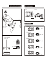
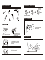
WIRELESS PARKING SENSOR
US NUMBER PLATE DESIGN
USER’S MANUAL
GENERAL INSTALLATION DIAGRAM
DECTECTING RANGE
Top View
Side View
Display
Red wire + reversing light wire
Black wire - ground
0
1.0
0
8.0(feet)
1.0
8.0(feet)
DISPLAY STATUS
Safety Area 5.5-8.0 feet
se
ns
or
s
Red wire + 12V (ON/ACC)
Black wire - Ground
Silence
ce
ns
e
pl
at
e
F
Li
Safety Area 4.0-5.0 feet
F
Red wire + reversing light wire
Black wire - ground
dang......dang......
Danger Area 1.5-3.5 feet
F
Dang...dang...
ID learning hole
Display Top View
Alarm Area 1.0 feet
Red wire + 12V (ON/ACC)
Black wire - Ground
A
B
F
Dang.......
Display Front View
C
Alarm Area <1.0 feet
License Plate Sensors
UP
F
Dang.......
SENSOR INSTALLATION DIAGRAM
INSTALLATION TOOLS
Smooth slope
Smooth round objects
Objects absorbing
wave, e.g. Cotton
Objects hard to be detected
DISPLAY INSTALLATION
INSTALLATION
The display should be installed
where easily seen.
1. Firstly, disassemble the license
plate.
2. Drill with the original driller,
according to the location of the
license plate sensor.
SENSOR DETECTING
A
B
C
3. Insert the cable of the license plate
sensor into the hole, and then tighten
the screws.
8.0ft
4. Hide the wires in good order
according to various cars.
ID LEARNING
WIRELESS PARKING SENSOR FOR US NUMBER PLATE DESIGN
This system consists of digital control box of MCU, ultrasonic sensors and display. This system detects
the distance between the car and the back obstruction by the ultrasonic sensors installed at the rear
bumper. Distance signal is sent via wireless transmitter. The distance and direction of obstruction will be
displayed via the digital display and imitation progress bar display with step-up sounds, the change of alarm
sounds, progress bar and figures, the driver could judge the distance to avoid accident
MAIN FUNCTIONS
LCD display distance
Wireless transmission of detected distance
Imitation progress bar display
ID code learning
"DangDang" alarm sound
Easy installation
Volume adjustable
Controller working temperature: -30 - +70 degree Celsius
Display working temperature: -20 - +70 degree Celsius
Size of display: 80.4 x 49.8 x 30.2mm
Stage
Alarm Sound
Digital Display
Silence
.
Off
Off
>8.5 feet
F
NOTE
ALARM MODE
Distance
Press the button
Picture A
TECHNICAL SPECIFICATIONS
Rated voltage: DC 12V
Working voltage: DC 9V-16V
Rated working current: 20-150mA
Detecting range: 1.0-8.0 feet
Each license plate sensor has a unique ID to ensure the
confidentiality and reliability of data transmission during
communication with corresponding display. The display
has the function of learning ID, in order that the user could
replace the display or control box if necessary. Operation
as follows:
1. Connect the license plate sensor according to the
diagram, then select reverse gear to activate the
license plate sensor.
2. Connect the display with power. Press the button on
the display back. The display system will store the ID
of the control box automatically. See picture A
Indicator Light
5.5~8.0 feet
1
Silence
5.5~8.0
4.0~5.0 feet
2
Dang……Dang……
4.0~5.0
1 time/sec
2.5~3.5 feet
3
Dang…Dang…
2.5~3.5
2 times/sec
1.5~2.0 feet
4
Dang…Dang…
1.5~2.0
4 times/sec
1.0 feet
5
Dang……
1.0
On
0.0~0.5 feet
6
Dang……
0.0
On
Direction indicator of left , right, middle.
INSTALLATION STEPS
1. Choose the position for license plate sensors
2. Locate the position and drill
3. Install the license plate sensors and hide the wire
4. Install display
5. Connect the whole system according to the General Installation Diagram
1. The vehicle must be off during installation.
2. Its performance may be affected in following situations: heavy rain, gravel road, bumpy road sloping
road and bush, very cold, hot or moist weather, or the sensor is covered by ice, snow or mud.
3. Test the system to make sure it works normally before using.
4. This system is a reversing aid and the manufacturer will take no responsibility for any accident after
the kit is installed.