1
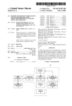
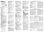
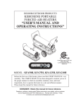
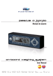
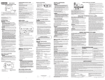
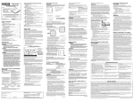
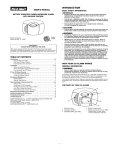
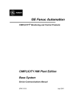
C400V C500V C600V
C400FV C500FV C600FV
R
Smarteye
Model Description:
CX00
LED Display(X=2 3 4 5 6 The number of sensors.)
CX00V VFD Display(X=2 3 4 5 6 The numbe r o f sensors.)
CX00F Flash Sensor with LED display
CX00FV Flash Sensor with VFD display
cable
Display cable
1 piece
6.Driller
1 piece (option)
s
15
-40
-50
response:
---+80
---+90
(1-7 feet)
with LED or VFD
person for help,
Brake light (Flash model)
display cable (6.5m)
6
2
2
3 Digital distance show
Beep switch
(high/low/off)
mini USB
lndicator
VFD display
Brake light (Flash model)
display cable (6.5m)
6
2
2
Back ground light
Beep switch
Cable
lndicator
3 Digital distance show
LED display
display
(display cable)
2.Installation of Power supply wires: For C500. C600 model: It comprise 3 wires totally.
Red Wire Number 1 is 6 meters ; Red Wire Number 2 is 2 meters; Black Wire Number3 is 2
meters . C200.C300.C400. S400 have 2 wires total, Red Wire Number2 is 2meter long,
Black Wire Number3 is 2 meters long.
No.1 Red Wire Number 1 should be connected to the "on" block or brake light (Flash
model) when switch on ignition
No.2 Red wire number 2 should be connected to the power of the back up light.
No.3 Black Wire Number 3 should be connected to the ground of the back up light
Pay attention to the aesthetics when installing the wires.
3.Installation of display cable ( cord or cable):Routing display cable from the left side of the
display panel and following the path of car wiring as to the diagram, spliced the display cable
and pay attention to the concealment and the aesthetics , at last, plug one side of the display
cable into the appropriate socket .
4.Installation of Parking System Module: Parking System Module is normally installed
inside the trunk of the car, adhesive at the two side of the trunk by the double-sided tape and
nylon lock. Pay attention leave far away from any obstruction.
MAIN BOX
WIRE HIDED IN THE SEAL
DRILL
SENSOR WIRE CONNECTING
5. Installation of the Parking sensors:
a) Pay attention to find the accuracy position to drill holes and make sure to connect the
cable correctly, we suggest the clients to take a measurement and before you drill holes and
perform the installation refer to the user manual.
b) For A-D, 4sensors (C400) should installed in the back bumper of the car, E-F, should
installed in the front bumper of the car. (C500,C600).
Disp. window
E
F
MAIN BOX
A
B
C
SENSOR
D
Backup light power
Brake light (flash model)
c) According to the amount of the parking sensors and the width of the back bumper,
confirm the installation distance from the height and the distance as to the diagram, the drill
the hole in the bumper or other proper place (we provide the special drill head). Check the car
bumper, make sure it reach the installation standard. (check the internal structure of the
bumper, make sure it is above 45cm from ground level when installing and the angle should
be parallel to the ground). After having drilled the holes (recheck the diameters of the drill head),
the sharp edge of the holes should be polished smooth.
A
B
C D
0.4-0.8m
0.3-0.4m
d) After having drilled the holes, install the parking sensors in the hole and the best height
should be 50cm from ground level, to angle the sensors a bit up according to the installation
and the slope of the bumper surface, the plastic washer should be installed upward. Adjust the
direction of the parking sensors, do not cut the wires and leave the wires about 10cm extra to
avoid any damage when pulling wires too tight.
e) Plug one sensor into the appropriate socket, switch on ignition and select reverse, the
display panel show the correct distance, repeat the procedure for the remaining sensors.
f) After testing the sensors, leave all the sensors connected. Ensure there is no wrong
connection according to the diagram, otherwise it could alarm incorrectly.
6. Leave all the connecting wires a bit longer to avoid the looseness when driving,
particular care should be taken to avoid the damage of the connector, recheck the position of
the sensor to ensure that they are not direct toward to the ground.
Product Adjustment Test
After the installation, we can test the production now
1.Near-vertical sensing scope diagram
2.Horizontal sensing scope diagram
3. Frontal distance:
When you engage to power on engine, frontal system (E. F. sensor) are automatically
activated, the sensing range should be: 0.3m-1.2m
They send and receive ultrasonic radio waves which bounce off obstacles and alert you to
their presence. there is a internal buzzer that gradually increases in frequency as you approach
the object. A continues tone denotes that you are within 0.5 meters. When encounter the red
light, the internal buzzer will stopped after 10 seconds if the distance of the obstacles without
change, but the display panel still show the distance of the object.
The display panel will show the distance of the obstacles without buzzing if the object is
beyond 0.5 meters.
4. Rear distance:
When you engage in reverse gear the frontal and rear system are automatically activated,
the distance response for rear sensors should be 0.3-1.8 meter, 0.3-0.5 meter for frontal
sensor. display panel shows the digital read out with buzzer as "0.00" when the obstacles are
within 0.3 meter. It shows the relatively minimal distance from A-E. the system will released
when you drive away from the parking lot and display panel will back to multi-functional again.
5. The system alarms the distance of the obstacles while reversing, it detect the direction
of the sensor as well, direction indicator lamps show the directions, it will buzz gradually when
obstacle is within 1.8 meters.
6. To avoid the inertia car accident, it is precision designed byus. The system will alert
driver to brake the car on time when any obstacles are within 0.3 meter, the display panel will
show as: 0.0and the internal buzzer will audible at the time being.
7. Pressing the temperature test button, the display panel shows the temperature of the
car. It will disappear after 5 seconds. (C600T only)
8. Carbon monoxide detection and alarm automatically if the CO density in your car is
over 100ppm (UL2034 standard). as you power on the engine, carbon monoxide detection
will clean automatically for 8 seconds. It starts to detect the CO density after one minute and
clean once again in every 30 minutes. (C600C only)
9. Please notice: during heavy raining day, and driving in a bumpy road or sand; or the
sensor was icing or covered with snow or mud. All these factors will effect the result of the
detection.
10. Please note that this positional ultrasonic parking is designed as an aid and should
not replace the need to drive carefully.
11. The specifications of the products in this manual is just for reference, the content
might be changed without notice ahead and the company keep the final explanation right for
the manual.
Warranty Card
Model:
Note:
Dealer
Name of the company:
Tel:
Signature and the seal:
Client
Name of the company:
Address:
Post number:
Date of the purchasing:
Servicing record:
1.
2.
3.
4.
5.
6.
7.
8.
Tel: