1
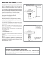
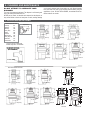
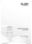
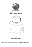
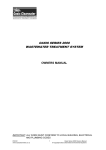
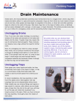
Food Waste Disposer
Instruction Manual
See insert for specific information about your new disposer
NOTE:
This Food Waste Disposer has been designed to operate at 220/240V~, 50/60 Hz household
current exclusively. Using any other voltage or Hz adversely affects performance.
IMPORTANT:
Read all instructions thoroughly. Keep this guide for future reference.
CAUTION:
Be sure to review SAFETY INSTRUCTIONS FIRST PERTAINING TO A RISK OF FIRE,
ELECTRICAL SHOCK OR INJURY TO PERSONS before using disposer.
Record important disposer information here
Model Number*
Serial Number*
*Above information appears on the label affixed to bottom of the disposer. For your convenience,
write down the model and serial numbers prior to installation.
IMPORTANT SAFETY INSTRUCTIONS
INSTRUCTIONS PERTAINING TO A RISK OF FIRE, ELECTRIC SHOCK OR INJURY TO
PERSONS. SAVE THESE INSTRUCTIONS.
WARNING – When using electrical appliances,
basic precautions should always be followed,
including the following:
1.
2.
3.
4.
5.
6.
7.
8.
Read all instructions before using the appliance.
To reduce the risk of injury, close supervision is necessary when
an appliance is used near children.
Do not put fingers or hands into a waste disposer.
Turn the power switch to the off position before attempting to clear
a jam or remove an object from the disposer.
When attempting to loosen a jam in a waste disposer, use a long
wooden object such as a wooden spoon or the wooden handle of
a broom or mop.
When attempting to remove objects from a waste disposer use
long-handled tongs or pliers. If the disposer is magnetically
actuated, non-magnetic tools should be used.
To reduce the risk of injury by materials that may be expelled by
a waste disposer, do not put the following into a disposer: clam
or oyster shells; caustic drain cleaners or similar products; glass,
china or plastic; large whole bones; metal, such as bottle caps,
tin cans, aluminum foil or utensils; hot grease or other hot liquids;
whole cornhusks.
When not operating a disposer, leave the stopper in place to
9.
10.
11.
12.
13.
14.
reduce the risk of objects falling into the disposer.
DO NOT operate disposer unless splash guard is in place.
For proper grounding instructions see the ELECTRICAL
CONNECTION portion of this manual.
Installation of this appliance must be done in
accordance to local plumbing codes and laws.
If the supply cord is damaged, it must be replaced by the
manufacturer, its service agent, or authorized person in order to
avoid hazard.
This appliance is not intended for use by persons (including
children) with reduced physical, sensory or mental capabilities, or
lack of experience and knowledge, unless they have been given
supervision or instruction concerning use of the appliance by a
person responsible for their safety.
Children should be supervised to ensure that they do not play with
the appliance.
IM-UK-INTL-121
1. REMOVAL OF OLD UNIT
TYPICAL INSTRUCTIONS, YOUR MODEL MAY VARY.
Before starting this step, turn off electrical
power at the circuit breaker or fuse box. Unplug
disposer.
If your old mount is the same type as the mount on your new disposer,
just reverse the assembly instructions found in section 3. If your new
mount system is different, follow these instructions:
A. Use a pipe wrench to disconnect drain line where it attaches to
disposer discharge elbow (see 1A).
B. Remove disposer from sink flange by turning mount ring to
the left clockwise (see 1B). If you are unable to turn the mount
ring, tap on one of the extensions from the ring with a hammer.
Some mounting systems have tubular extensions. Inserting a
screwdriver into one tube will provide additional leverage for
turning the mount ring (see 1B). Some disposers may require the
removal or loosening of nuts from the mount screws (see 1C).
Some disposers may require the removal of a clamp.
1A
Caution: Be sure to support the disposer while
performing this step or it may fall when the mounting
ring is disconnected from the mounting assembly.
C. To remove remaining mount system from the sink, loosen mount
screws, push mount ring up. Under it is the snap ring. Use
screwdriver to pop off ring (see 1D). Remove mount ring,
protector ring and gasket from sink flange. Some mounts will
require the unscrewing of a large ring holding the sink flange in
place. Pull sink flange up through sink and clean off old putty
from sink.
IMPORTANT: This is a good time to clean out the trap and
drain lines by running a drain auger or plumber’s snake
before installing your new disposer.
1B
1D
1C
2. DISHWASHER CONNECTION
If you are utilizing a dishwasher, complete the following procedure. If
dishwasher is not to be connected go on to section 3.
A. Using a drill. Drill out the entire plug. (see 2A) When knockout
plug falls into disposer, you may remove it or grind it up when the
disposer is used. This will not damage the disposer in any way,
but may take some time to grind).
B. Connect dishwasher hose (see 2B) using hose clamp. Make
sure all plumbing connections are tight and in accordance with all
plumbing codes and ordinances. Run water and check for leaks.
* AIR GAP
2B
RUBBER
HOSE
DISHWASHER
HOSE
2A
DRAIN
KNOCK/
DRILL OUT
PLUG
DISPOSER
*Air gap may not be required for all
installations. Check local plumbing
codes.
3. INSTALLATION OF MOUNTING ASSEMBLY
READ COMPLETELY BEFORE STARTING
Speed Master Mount System
* REMOVABLE SPLASH
GUARD
NOTE: Pay close attention to the order of mount assembly parts, as they have been
correctly assembled by the factory (see 3A). Also, reference the cushion mount detail
in illustration 3G for the proper position of the cushion mount.
SINK FLANGE
SINK FLANGE
GASKET
NOTE: Try practicing this assembly before you get under the sink to get the “feel” of
how the parts fit together.
A. Disassemble mount assembly from disposer by turning mount ring to the left
(clockwise) and remove.
FIBER GASKET
SUPPORT RING
MOUNT RING
3A
CUSHION MOUNT
SPEED MASTER MOUNT SYSTEM
B.
C.
D.
E.
F.
G.
H.
I.
Raise mount ring toward top of sink flange. Remove cushion mount. Remove mount
ring. You may want to practice installing the cushion mount at this point before you
are under the sink. See paragraph H. Also see the “Important Notice: Cushion Mount
Detail.”
Unscrew support ring from sink flange and remove fiber gasket. You are now left with
sink flange and rubber gasket.
The rubber gasket is used instead of plumbers putty or silicon
with stainless steel sinks. Other sinks will require putty.
If no putty is used, insert sink flange through rubber gasket into sink opening. Do not
rotate sink flange once it is seated.
3B
If you use putty instead of the gasket, form a ring around
underside of sink flange (see 3D). Insert flange into sink
opening, press down hard to squeeze out excess putty (see
3B). From under sink, trim off excess putty flush with bottom
edge of sink opening.
From underneath sink, slip fiber gasket onto exposed sink
flange. With arrows pointing up, screw support ring onto the sink flange, hand tighten
until the sink flange will not move. At this point you may want to insert stopper in sink
and fill with water to check sink flange seal and ensure there are no leaks.
Place mount ring over sink flange and hold in place while installing cushion mount
(large side down) so the groove on the inside of cushion mount fits over lip on sink
flange, similar to putting the lid on a plastic container (see 3E, 3F & 3G). Please read
important notice below.
The disposer must be installed so that the reset button is readily accessible.
RUBBER SINK
FLANGE GASKET (OR
PUTTY)
FIBER GASKET
SUPPORT RING
(NOTE ARROWS
INDICATING UP)
MOUNT RING
TIGHTENING EARS
GROOVE
CUSHION MOUNT
DISHWASHER
INLET
ELBOW GASKET
SCREWS
HOPPER
ELBOW
FLANGE
RESET BUTTON
(FRONT)
DISCHARGE ELBOW
* Stopper & Splash Guard
not used with Batch Feed model
3E
3D
REMOVABLE
*SPLASH GUARD
SINK
FLANGE
IMPORTANT NOTICE: CUSHION MOUNT DETAIL
When the cushion mount is
installed correctly, the lip
of the sink flange fits into
the groove on the inside
of the cushion mount and
mount ring can be pulled
downward over cushion
mount and will be free to
rotate. The bottom bead
of the cushion mount acts
as a gasket between the
bottom of the sink flange
and the top of the disposer.
See illustration 3G.
3C
* STOPPER
SINK
3G
CUSHION MOUNT DETAIL
SINK
TOP OF SINK FLANGE
SINK
FIBER
GASKET
BOTTOM
BEAD OF
CUSHION
MOUNT
RUBBER
GASKET
3F
4. ELECTRICAL CONNECTIONS
WARNING: THIS APPLIANCE MUST BE
EARTHED. IN THE EVENT OF A MALFUNCTION,
EARTHING PROVIDES A PATH OF LEAST
RESISTANCE FOR THE ELECTRICAL CURRENT,
THUS REDUCING THE RISK OF ELECTRICAL
SHOCK.
MOUNT RING
SUPPORT
RING
SINK
FLANGE
OPEN AREA, NO
OBSTRUCTION
SUPPORT
RING
MOUNT RING
SHOULD BE FREE TO
MOVE UP & DOWN
GROOVE
BOTTOM
BEAD
BOTTOM
“LIP” OF
SINK
FLANGE
CUSHION
MOUNT
The rating for these disposers are 220/240V~, 50/60 Hz and they should be
connected to a main distribution board or consumer unit.
Prior to connecting the electrical supply, the installer must be thoroughly
familiar with electrical power and procedures. If the installer is not, an
electrician should be contacted.
WHEN USING THE ATTACHED PRE-WIRED
MOLDED PLUG AND LEAD (SEE 4A).
These disposers are engineered to be connected to a 220/240V~-50/60
Hz electrical supply through the attached three-pin plug and into a wired
socket. The disposer must be protected by a BS 1363 13 Amp fuse.
The fuse is included within the molded plug and lead, attached to the
disposer.
4A
ELECTRICAL CONNECTION FOR
DISPOSER PROVIDED WITH PREWIRED MOLDED PLUG AND LEAD.
For Continuous Feed Only - Not Batch Feed
13 AMP FUSED
DOUBLE POLE
SWITCHED SPUR
WALL MOUNTED
The 13 Amp double pole switched spur switch should be positioned higher
than the sink countertop and at a minimum of one meter from the side of
the sink, away from water splashes and out of the reach of children. This
spur switch must be a double pole with at least 3mm contact separation
in each pole. 20 Amp DP switches BS 3676 meet this condition.
To avoid accidentally leaving the disposer running, a switch with a neon
indicator lamp is suggested. A 13 Amp ASTA approved fuse, to BS 1363
must be fitted in the fuse carrier of this spur switch.
PLUG SOCKET
ELECTRICAL CONNECTIONS:
Simply insert the plug into the socket wired as previously described.
WHEN NOT USING THE PRE-WIRED PLUG BUT WIRING DIRECT
WITH FIXED WIRING (SEE 4B).
The switches used must be double pole type and have at least a 3mm
contact separation in each pole (20 Amp DP switches to BS 3676 meet
this requirement).
Prepare the tips of the wires of the electrical lead and attach to the junction box. Disconnect the junction box from the electrical supply before
making the following connections:
The green and yellow wire must be connected to the terminal marked in
one of the following ways:
• with the letter “E”
• by the earth symbol ( )
• coloured green or green and yellow.
4B
FIXED WIRE ELECTRICAL CONNECTION.
13 AMP FUSED
DOUBLE POLE
SWITCHED SPUR
WALL MOUNTED
The brown wire must be connected to the terminal that is marked with
the letter "L".
The blue wire must be attached to the terminal that is marked with the
letter "N".
(NOTE: As your disposer has a molded plug on the lead and the plug
is not to be used, cut it off and dispose of it wisely. A molded plug with
a loose lead with disconnected wires can be hazardous as an electrical
shock hazard could occur should such a plug be inserted into a 13 Amp
socket anywhere within the home.)
13 AMP FUSED
SPUR MOUNTED
UNDER SINK
IS THE DISPOSER EARTHED?
WARNING: THIS APPLIANCE MUST BE EARTHED.
In the event of a malfunction of breakdown, earthing reduces the risk of shock. This disposer must be
connected to an earthed, metal, permanent wiring conductor and connected to the equipment earthing
terminal or lead on the disposer.
GROUNDING INSTRUCTIONS
FOR WASTE DISPOSERS EQUIPPED WITH A
GROUNDED PLUG-IN POWER CORD.
B. This appliance must be grounded. In the event of a malfunction
or breakdown, grounding provides a path of least resistance
for electric current to reduce the risk of electric shock. This
appliance is equipped with a cord having an equipment-grounding
conductor and a grounding plug. The plug must be plugged into
an appropriate outlet that is properly installed and grounded in
accordance with all local codes and ordinances. If the supply cord
is damaged it must be replaced by the manufacturer, its service
agent or similarly qualified person in order to avoid a hazard.
The appliance must be installed so that reset button is readily
accessible.
5. ATTACHING DISCHARGE ELBOW
A.
B.
Connect waste elbow to the disposer (see 5A), proceed to step 6 and then
connect bottom of the elbow by tightening the slip nut (see 5B).
If you are connecting to a dishwasher, return to section 2B. If not, make sure all
plumbing connections are tight and in accordance with all plumbing codes and
ordinances. Run water and check for leaks.
RUBBER
GASKET
5A
5B
6. CONNECTING DISPOSER TO MOUNT ASSEMBLY
A.
B.
C.
D.
Line up disposer under mounting assembly. Guide hopper
projections into mount ring slots. Turn mount ring about 1/4” to
right so that disposer is temporarily supported (see 6A).
Turn mount ring and disposer until disposer elbow lines up with
trap (see 6B).
Turn mount ring to the right (counter-clockwise) until it reaches
the locking position as shown (6D). Hopper projections must be
to extreme left of mounting slots (see 6C & 6D).
If mount ring is hard to turn, you may add a small amount of
petroleum jelly or liquid soap to hopper projections. Run water and
check for leaks.
6A
SLOT
6B
PROJECTION
ELBOW
TRAP
6C
6D
LOCKING DETAIL
HOPPER PROJECTION IN
“SUPPORTED” POSITION
HOPPER PROJECTION IN
“LOCK” POSITION
MOUNT
RING
7. OPERATING INSTRUCTIONS
The Anti-Jam Swivel Impellers make a clicking
sound as they initially swing into place. This
indicates normal operation.
A. Remove sink stopper. Turn on a medium flow of cold water.
B. Turn switch to ON position; your motor is turning at full speed and
ready to use.
C. Scrape in food waste. Down the drain go table scraps, peelings,
rinds, seeds, pits, small bones and coffee grounds. To speed up
food waste disposal, cut or break up large bones, rinds and cobs.
Large bones and fibrous waste require considerable grinding
time and are more easily thrown away with other trash. Do not
be alarmed that the disposer slows down while grinding. The
D.
E.
disposer is actually increasing torque (grinding power) and is
operating under normal conditions.
Before turning disposer off, let water and disposer run for approximately 15 seconds after shredding or grinding stops. This assures
that all waste is thoroughly flushed through trap and drain.
It is not recommended to use hot water while running disposer.
Cold water will keep waste and fats solid so disposer can flush
away particles.
TIPS FOR SUCCESSFUL OPERATION
A.
B.
C.
Be sure disposer is empty before using your dishwasher so it may drain properly.
You may want to leave the stopper in the drain when not in use to prevent utensils and foreign objects from falling into the disposer.
Your disposer is ruggedly built to give you many years of trouble free service. It will handle all normal food wastes, but it will NOT grind or
dispose of such items as plastic, tin cans, bottle caps, glass, china, leather, cloth, rubber, string, clam and oyster shells, aluminum foil or
feathers.
8. CLEANING AND MAINTENANCE
DO NOT ATTEMPT TO LUBRICATE YOUR
DISPOSER!
The motor is permanently lubricated. The disposer is self cleaning and
scours its internal parts with each use.
NEVER put lye, bleach, or chemical drain cleaners into the disposer, as
they cause serious corrosion of metal parts. If used, resulting damage
can be easily detected and all warranties are void. Mineral deposits
from your water can form on the stainless steel turntable, giving the
appearance of rust. DO NOT BE ALARMED, the stainless steel turntables used will not corrode.
TYPICAL INSTALLATIONS
* Dimensions are mm.
Economy
Standard
Mid-Duty
Heavy Duty
Deluxe
Premium
Mid-Duty BF
Heavy-Duty BF
Deluxe BF
Premium BF
231
231
249
255
255
255
303
310
310
310
SINGLE BOWL
*approx
Standard
Economy
Mid-Duty
Choice of Trap is Optional.
Bottle Traps are not suitable.
Deluxe
Heavy Duty
Round Shell Dimensions
Premium
Batch Feed Dimensions
178
233
70
430
137
Economy
Standard
Mid-Duty
Mid-Duty BF
220
220
240
460
70
240
494
70
140
147
Heavy Duty
Deluxe
Premium
38
Deluxe BF
Premium BF
9. TROUBLESHOOTING
Before seeking repair or replacement, we
recommend that you review the following:
LOUD NOISES: (Other than those during grinding of small bones and
fruit pits): These are usually caused by accidental entry of a spoon,
bottle cap or other foreign object. To correct this, turn off electrical
switch and water. After disposer has stopped, remove splash guard,
remove object with long handled tongs, and replace splash guard.
UNIT DOES NOT START: Unplug power cord or turn either the wall
switch or breaker box switch to “OFF” position, depending on your
model and wiring configuration. Remove stopper and/or splash guard.
Check to see if turntable will rotate freely using a wooden broom handle.
If turntable rotates freely, replace splash guard and check reset button
to see if it has been tripped. Reset button is red and located on the front
of the disposer. Push button in until it clicks and remains depressed.
Reset Button should be pressed only once.
If reset button has not been tripped, check for shorted or broken wire
connecting to disposer. Check electrical power switch, fuse box or
circuit breaker. If wiring and electrical components are intact, the unit
may have internal problems that require service or replacement.
handle (see 9A) and remove object. If no foreign object is present,
there may be internal problems.
LEAKS: If the unit leaks at the top, it may be due to:
1. Improper seating of sink flange (gasket centering, putty or
tightening).
2. Support ring not tightened properly.
3. Defective or improperly installed cushion mount.
If unit leaks at the waste elbow, leak may be due to improper tightening
of elbow flange screws.
9A
DO NOT PRESS THE RED
RESET BUTTON UNLESS
POWER IS SWITCHED OFF
AT THE POWER POINT.
REMOVE
SPLASH
GUARD
TURNTABLE
IF TURNTABLE DOES NOT ROTATE FREELY: Turn off disposer, then
check for any foreign object lodged between the turntable and grind
ring. Dislodge object by rotating table with a wooden spoon or broom
10. ELECTRICAL INFORMATION
REPLACING
THE
FUSE
IN
MOLDED
PLUGS:
The correct fuse cover must be refitted when changing the fuse.
Remove the fuse cover and slide the fuse out. Replace it with a 13 Amp
ASTA fuse (approved to BS 1363). Should the fuse cover be lost or
damaged, an exact replacement should be used. These are available
from an approved service agent, listed below. Never use the plug
without the fuse cover fitted.
If a rewirable plug is to be fitted to the supply lead, it
should be connected as follows:
· When connected to a BS 1363 fused plug, a BS 1362 ASTA approved
13 Amp fuse must be fitted.
· As the colours of the wires in the supply lead of this appliance may
not correspond with the coloured markings identifying the terminals in
your plug, proceed as follows:
· The green and yellow wire must be connected to the terminal in
the plug which is marked with the letter “E” or by the earth symbol or
coloured green or green and yellow.
· The brown wire must be connected to the terminal which a marked
with the letter "L" or coloured red.
· The blue wire must be connected to the terminal which is marked with
the letter "N" or coloured black.
REWIRABLE PLUG FIT INSTRUCTIONS
WARNING: This appliance must be earthed. The wires
in the supply lead are coloured in accordance with
the following code: Green and Yellow = Earth; Blue =
Neutral; Brown = Live.
IMPORTANT:
If the supply lead is damaged, it must be replaced by the manufacturer
or its service agent.
ANAHEIM MARKETING INTERNATIONAL
4332 E. La Palma Avenue Anaheim, California 92807
Telephone: 714.993.1707 Fax: 714.993.1930
Website: www.AnaheimMarketing.com E-Mail: [email protected]