1
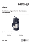
Installation, Operation & Maintenance Instructions Please leave this instruction booklet with the home owner as it contains important guarantee, maintenance and safety information Read this manual carefully before commencing installation. This manual covers the following products: 12/50 12/50 Pt. No. 46164 Pt. No. 46212 12/50 12/50 Pt. No. 46166 Pt. No. 46168 12/50 12/50 Pt. No. 46167 Pt. No. 46169 CE compliant product PRODUCT DESCRIPTION The standard range of motors are suitable for a supply of either 12 V d.c. or 24 V d.c. dependant upon which model selected. Optional motors are available to suit different voltages, consult Stuart Turner Ltd for further details. APPLICATION The range of centrifugal pumps is designed to pump clean fresh water. Other clean, non aggressive, non explosive liquids with similar characteristics to water may be pumped. Consult Stuart Turner for advice on such applications. The pumps can be used for pressure boosting, fluid transfer and distribution. They are suitable for flooded suction applications. Alternatively a maximum suction lift of 4.6 metres is permitted when using a Stuart footvalve/strainer. This pump set must not be used for any other application without the written consent of Stuart Turner Limited and in particular, must not be connected directly to the mains water supply, or used outside the conditions specified in the technical specification. This appliance can be used by children aged from 8 years and above and persons with reduced physical, sensory or mental capabilities or lack of experience and knowledge if they have been given supervision or instruction concerning use of the appliance in a safe way and understand the hazards involved. Children shall not play with the appliance. Cleaning and user maintenance shall not be made by children without supervision. Children should be supervised to ensure that they do not play with the appliance. Please read installation details carefully as they are intended to ensure this product provides long, trouble free service. Failure to install the unit in accordance with the installation instructions will lead to invalidation of the warranty. STORAGE If this product is not installed immediately on receipt, store in a dry, frost and vibration free location in its original packaging. Cont ... -2- CONTENTS Page Checklist . . . . . . . . . . . . . . . . . . . . . . . . . . . . . . . . . . . . . . . . . . . . . . . . . . . . . . . . 3 Important Facts - read before commencing installation . . . . . . . . . . . . . . . . . . . 4 Location . . . . . . . . . . . . . . . . . . . . . . . . . . . . . . . . . . . . . . . . . . . . . . . . . . . . . . . . 5 Pump Connections . . . . . . . . . . . . . . . . . . . . . . . . . . . . . . . . . . . . . . . . . . . . . . . . 9 Electrical Installation . . . . . . . . . . . . . . . . . . . . . . . . . . . . . . . . . . . . . . . . . . . . . . . 12 Commissioning . . . . . . . . . . . . . . . . . . . . . . . . . . . . . . . . . . . . . . . . . . . . . . . . . . . 15 Maintenance . . . . . . . . . . . . . . . . . . . . . . . . . . . . . . . . . . . . . . . . . . . . . . . . . . . . . 16 Technical Specification . . . . . . . . . . . . . . . . . . . . . . . . . . . . . . . . . . . . . . . . . . . . . 18 Trouble Shooting . . . . . . . . . . . . . . . . . . . . . . . . . . . . . . . . . . . . . . . . . . . . . . . . . 20 Guarantee . . . . . . . . . . . . . . . . . . . . . . . . . . . . . . . . . . . . . . . . . . . . . . . . . . . . . . . 22 Cont ... -3- CHECKLIST IMPORTANT: With the pump removed from its packaging check for any damage prior to installation. If any damage is found contact Stuart Turner Ltd within 24 hours of receipt. A Fig. 1 Item Description A Pump Qty 1 Your product may vary slightly from the picture above. Cont ... -4- 1 IMPORTANT FACTS: READ BEFORE COMMENCING PUMP INSTALLATION A. Water storage capacity. 1.11 The water storage capacity must be sufficient to meet the flow rates required by the pumped equipment and any other water using fittings and appliances, which may be operated simultaneously. 1.12 Ensure the pump is primed as described in the priming section before starting, damage to the shaft seal will result otherwise. See Section 5 - Commissioning. B. Water temperature The water entering the pump must be controlled as follows: 1.13 The maximum allowable water temperature is 80 oC. 1.14 The minimum allowable water temperature is 4 oC. 1.15 DO NOT fit a pump if the hot water is heated via a method whereby the water temperature cannot be controlled, such as solar or solid fuel you must consult the PumpAssist team on +44 (0) 844 98 000 97. C. Pipework - General 1.16 Secure pipework: Ensure pipework to and from pump is independently supported & clipped to prevent forces being transferred to inlet and outlet branches of pump. 1.17 Flux: Solder joints must be completed and flux residues removed prior to pump installation (flux damage will void any warranty). 1.18 Pipework design: Care should be taken in the design of pipework runs to minimize the risk of air locks e.g. use drawn bends rather than 90o bends. 1.19 DO NOT introduce solder flux to pumps or pump parts manufactured from plastic. 1.20 DO NOT allow contact with oil or cellulose based paints, paint thinners or strippers, acid based descalents or aggressive cleaning agents. 1.21 DO NOT install a non-return valve, or devices which contain non-return valves, in the suction (inlet) pipework to the pump. The pump must be free to vent to the supply tank at all times. Exceptions can be made in the case of suction lift installations when a footvalve is required. 1.22 DO NOT connect this pump to the mains water supply. D. Plumbing Installation Regulations 1.23 The plumbing installation must comply with “The Water Supply (Water Fittings) Regulations 1999” and “BS 6700” building regulations where applicable. 1.24 The plumbing installation must be installed by a qualified person. 1.25 The electrical installation must be carried out in accordance with the current national electrical regulations. 1.26 The electrical installation must be installed by a qualified person. Cont ... -5- 2 LOCATION - GENERAL 2.16 2.17 2.18 2.19 2.20 2.21 2.22 2.11 Access: For emergencies and maintenance the pump must be easily accessible. 2.12 Protection: The pump must be located in a dry position, frost free and protected from freezing, particularly when installed in a loft (not recommended). 2.13 Ventilation: Ensure an adequate air flow to cool the pump. Separate the pump from other appliances that generate heat. An 80 mm (3 “) air gap must be maintained around the pump. 2.14 Safety: The motor casing can become very hot under normal operating conditions. Care must be taken to ensure it cannot be touched during operation. 2.15 Water retention: Site the pump in a location where in the unlikely event of a water leak, any spillage is contained or routed to avoid electrics or areas sensitive to water damage. Pump position: The pump must be positioned as close to the water source as possible. Ensure the pump is mounted in a position that allows easy access to the brush housing if required. Ambient temperature: The pump must be sited in a location where the maximum ambient temperature does not exceed 40 oC. Inline Strainer: When the pump is to be installed in areas where there is a risk of debris or scale build up within the system, it is recommended that the inlet pipework is fitted with an inline strainer. Noise: Care must be taken to reduce noise transmission when mounting the pump and that any noise is not amplified through loose panels or pipework. Do not screw down the pump. Direction of flow: Ensure the water flow is in the direction as shown in Fig. 2. Isolating valves: Separate isolating valves (non restrictive) must be fitted to allow easy pump service. When a footvalve is required on installations that incorporate automatic pump control, it is recommended that a suitable pressure relief valve be fitted in the discharge (outlet) pipework from the pump. Cont ... -6- 2.23 Pump Mounted Above Liquid Source (Suction Lift): These pumps are self priming and can be used in a suction lift installation providing the height of lift is within the limits specified in the limits of application section. A footvalve and strainer must always be used and the suction pipework size must match the pump. Lay the suction piping over the shortest possible distance and ensure there is a constant rise from the liquid source to the pump. Any high spots will cause air pockets to form, reducing system efficiency. Ensure all joints in suction pipework are completely airtight. Failure to comply will result in loss of prime. The intake of the footvalve/strainer should be positioned such that it cannot be blocked with debris or silt that are frequently found in the bottom of sumps and wells. When a footvalve is installed on installations that incorporate automatic pump control, it is recommended that a suitable pressure relief valve be fitted in the discharge (outlet) pipework from the pump. To prime the pump see Section 5.16. Outlet Inlet Fig. 2 Cont ... -7- 3 PUMP CONNECTIONS 3.11 Pump to pipework: Connect the pump to pipework using a G ¾ to suitable pipe fittings as required. Cont ... -8- 4 ELECTRICAL INSTALLATION 4.14 4.15 4.16 4.17 4.11 Regulations: The electrical installation must be carried out in accordance with the current national electrical regulations and installed by a qualified person. 4.12 Safety: Before starting work on the electrical supply ensure power supply is isolated. 4.13 DO NOT allow the supply cord to contact hot surfaces, including the motor shell, pump body or pipework. The cord should be safely routed and secured by cable clips. Earthing: The d.c. supply source to the motor could be from a battery, transformer, altenator or generator, hence there is no requirement or facility for earthing via the supply cable. However certain installations may require additional earthing arrangements to be considered. Static protection & EMC compliance: The motor can be connected to earth via it’s front mounting foot. This will maximise ability to discharge electro static energy and lightning interference. It will also assist EMC compliance. Additional earthing: Metallic inlet and outlet pipework should be cross bonded where the system continuity has been broken by flexible hoses or plastic components. Wiring Of Connection Unit: The motor is provided with a factory fitted power supply cord. This must be permanently connected to the supply source. The wiring in the power supply cord is coloured in accordance with the following code: Blue: Negative Brown: Positive The pump must run in an anticlockwise direction when looking at the pump inlet port. To ensure this happens the pump supply cord must be connected as follows: The wire coloured blue must be connected to the negative terminal of the supply source, marked with the symbol -. The wire coloured brown must be connected to the positive terminal of the supply source, market with the symbol +. 4.18 Fuses: The following fuse size should be used with the appropriate pump. Model Fuse Size (AMPS) 12/50 (12 V) 15 12/50 (24 V) 15 Fuse type should be of the delayed action type (type T or motor rated) with good time delay characteristics. The fuse performance variation in relation to ambient temperature should also be considered. Cont ... -9- 4.19 Supply Cord Extension: The pumps are fitted with a supply cord to the following specification:HO5VV-F2 X 1.5 mm² - 16 Amp rated cable If the supply cord is to be extended, a cord of the same specification should be used. Any connections or junction boxes used should be specifically suited for the application and installed in accordance with the manufacturers instructions. Cont ... - 10 - 5 COMMISSIONING 5.11 System Flushing: Some pumps incorporate plastic components that must not come into contact with solder flux, acid-based descalents or aggressive cleaning agents. The pipework system should be flushed out prior to the pump being connected to ensure any contaminants/chemical residues and foreign bodies are removed from elsewhere in the system. 5.12 Liquid Supply: Always ensure that water storage capacity is adequate to meet the demand. Ensure the pump chamber is full of liquid before starting the pump. Failure to do this could result in seal damage. To ensure dry running does not occur the pump must be primed as described in priming section below. Do not run pump dry. 5.13 Ensure electrical supply is compatible with the details that are stated on the pump rating plate. (The wrong voltage can be dangerous and may damage the pump.) 5.14 The motor casing can become very hot under normal operating conditions, care should be taken to ensure it cannot be touched during operation. 5.15 Do not run pump without terminal/brush guard correctly fitted. 5.16 Priming: a) Flooded suction installation (without priming plug). This pump range are self venting and hence no priming plugs are fitted. Turn on liquid supply and open outlet valve to allow pump to fill and vent. b) Flooded suction installation (with priming plug). The pump must be primed (filled with liquid) before starting. Turn on liquid supply, prime and vent the pump by unscrewing the priming plug (Fig. 4) slowly until all air escapes and liquid emerges. Re-tighten plug. c) Suction lift installation. Prime the suction pipework and pump by filling with liquid via the pump discharge connection or by filling the suction pipework before attaching to the pump. Priming Plug Without Priming Plug Fig. 3 With Priming Plug Fig. 4 - 11 - 5.17 Starting: a) Switch on power to the pump which will now be operational. b) Confirm the direction of rotation is correct by stopping and observing over run. The correct direction of rotation is anticlockwise when looking directly at the front of the pump casing. To reverse rotation see wiring diagram section. c) The pump should now be fully operational. d) Carefully check pump and pipework for leaks whilst pump running and stationary before leaving the installation unattended. 5.18 For Further Technical Support: Phone the Stuart Turner PumpAssist team on +44 (0) 844 98 000 97. Our staff are trained to help and advise you over the phone. Note: When pumps are installed in another manufacturers original equipment, please contact the manufacturer for advice. Cont ... - 12 - 6 MAINTENANCE 6.11 Routine maintenance to replace motor brushes will be required, provision should be made for easy access to the pump to allow repairs due to normal wear and tear and brush replacement. 6.12 Disconnect electrical supply before working on pump. 6.13 Turn off liquid supplies to the pump and release pressure by opening outlets before attempting maintenance. 6.14 If the installation is fitted with a footvalve and strainer or inline suction strainer, the strainer must be cleaned as necessary to ensure the pump has unrestricted flow. 6.15 After maintenance is completed, refer to commissioning section for instructions on restarting pump. 6.16 Brush replacement procedure: The pumps are fitted with brush motors. The brushes will require replacement when worn out. The brushes have a life expectancy of approximately 1000 hours running time, which will vary dependant upon motor loading. The bushes are replaced in the following way:- 1. Locate suitable size screwdriver or flat blade into the Brush Retaining Cap slot. Fig. 5 2. Carefully un-screw the Brush Retaining Cap until loose. Note: The Cap will ‘pop’ out under the force of the Brush Assembly Spring. Fig. 6 3. Carefully remove worn Brush Assembly from motor. Note: Carefully clean carbon dust from aperture with a soft brush. Fig. 7 Cont ... - 13 - Retaining Slot 4. Replace new Brush Assembly by fitting the carbon head into the retaining slot as shown. Note: the Brass Cap of the assembly also fits into this retaining slot - see section 5. Carbon Head Brass Cap Fig. 7 5. Push the Brush Retaining Cap against the spring tension and screw firmly into place until tight, noting that the Brass Cap of the assembly is correctly located in the retaining slot as shown in section 4. Note: DO NOT OVERTIGHTEN Fig. 8 6. Repeat the process for the opposite site. 6.17 Cleaners, Disinfectants and Descalents: Acid based descalents and aggressive cleaning agents must not come into contact with the pump. The pump must be removed from the system prior to the use of these products. The system should be flushed to remove all chemicals before the pump is re-connected. If in any doubt as to the suitability of the chemical solutions, please contact our PumpAssist helpline on +44 (0) 844 98 000 97. Cont ... - 14 - 7 TECHNICAL SPECIFICATION Pump Model 12/50 12/50 12/50 12/50 12/50 12/50 12 V d.c. 12 V d.c. 12 V d.c. 24 V d.c. 24 V d.c. 24 V d.c. 46164 46166 46167 46212 46168 46169 General Guarantee 1 year Features Pump type Centrifugal Mechanical seal Impeller Performance Nitrile / Carbon / Ceramic Acetal Brass Maximum head (closed valve) Viton / Carbon / Silicone Carbide Brass Brass Brass 14 metres Performance @ 10 l/min 1.2 bar 1.3 bar Performance @ 50 l/min 0.5 bar 0.6 bar Maximum flow 63 l/min 64 l/min 3.8 bar (38 metres) 3.7 bar (37 metres) Maximum working pressure* 500 kPa (5 bar) 40 oC Maximum ambient air temperature Min 4 oC / Max 80 oC Min / Max water temperature Maximum suction lift** 4.6 metres Maximum viscosity 50 secs redwood no. 1 9.5 centistokes Maximum no starts/hour Connections Pump connections Motor Type 30 G ¾ female Permanent magnet brush motor Duty rating Physical Acetal 13 metres Maximum static inlet pressure Electrical Nitrile / Carbon / Ceramic Viton / Carbon / Silicone Carbide Continuous (S1) Power supply / phase / frequency 12 V d.c. 24 V d.c. Current (full load) 14.2 Amps 15.0 Amps 8.3 Amps 8.2 Amps Power consumption 170 Watts 177 Watts 198 Watts 196 Watts Fuse rating 15 Amps Power cable (pre-wired) 1.5 metres Enclosure protection IPX4 Length 229 mm Width 105 mm Height (excluding hoses) 117 mm Weight (including fittings) 3.3 Kg 3.5 Kg 3.4 Kg 3.2 Kg 3.4 Kg Stuart Turner reserve the right to amend the specification in line with its policy of continuous development of its products. *Note: The maximum pressure that can be applied to the pump under any installation conditions. **Note: With footvalve fitted. 7.11 Noise: The equivalent continuous A-weighted sound pressure level at a distance of 1 metre from the pump does not exceed 70 dB(A). Cont ... - 15 - 8 TROUBLE SHOOTING GUIDE Symptoms Probable Cause Recommended Action Pump will not start. Electrical supply. Check power to motor. Check circuit breaker is set. Check the correct fuse is being used.. Brush gear in need of replacement. Pump runs, but no liquid is pumped. Air locked. Bleed pipework and pump to clear air. No liquid supply. Check the supply valves are turned on. Check outlet not restricted or blocked. Motor running backwards. Check motor is rotating in the correct direction, if not, reverse connections of the two incoming supply wires. Pump connections reversed. Check liquid connections are on the right way round. No flooded suction. Check the pump has a flooded suction and is primed. No footvalve. If a suction list exists fit a Stuart footvalve/strainer and ensure suction pipework is airtight. Low voltage. Check correct voltage is available at the pumps. Brush gear in need of replacement. Under size supply cable. Pump running slow/ low performance 8.12 Environment Protection: Your appliance contains valuable materials which can be recovered or recycled. At the end of the products’ useful life, please leave it at an appropriate local civic waste collection point. Cont ... - 16 - 9 THE GUARANTEE - 1 YEAR Congratulations on purchasing a Stuart Turner pump. We are confident this pump will provide many years of trouble free service as all our products are manufactured to the very highest standard. All Stuart Pumps are guaranteed to be free from defects in materials or workmanship for 1 year from the date of purchase. Within the guarantee period we will repair, free of charge, any defects in the pump resulting from faults in material or workmanship, repairing or exchanging the whole unit as we may reasonably decide. Not covered by this guarantee: Damage arising from incorrect installation, improper use, unauthorised repair, normal wear and tear and defects which have a negligible effect on the value or operation of the pump. Reasonable evidence must be supplied that the product has been purchased within the guarantee term prior to the date of claim (such as proof of purchase or the pump serial number). This guarantee is in addition to your statutory rights as a consumer. If you are in any doubt as to these rights, please contact your local Trading Standards Department. In the event of a claim please telephone ‘PumpAssist’ or return the pump and flexible hoses with the accessories removed e.g pipes etc. If you have any doubt about removing a pump, please consult a professional. +44 (0) 844 98 000 97 Proof of purchase should accompany the returned unit to avoid delay in investigation and dealing with your claim. You should obtain appropriate insurance cover for any loss or damage which is not covered by Stuart Turner Ltd in this provision. Please record here for your records. TYPE NO. SERIAL NO. DATE PURCHASED Cont ... - 17 - Installers – Register with Stuart Turner and move up to Approved Installer status We receive thousands of enquiries every month from people seeking a Stuart Turner installer and by registering your details with us, we can offer consumers the opportunity to quickly locate an installer in their area. Registration is free - simply click on the ‘register as an installer’ link on our homepage at www.stuart-turner.co.uk and complete a short form which will enable visitors to find your contact details on our web site ‘installer finder’. Alternatively use your smartphone to scan this QR code and go straight to the form. We’ll do the rest! In addition we will ensure you receive advance notice on all new product launches and access to any special offers or promotions. Following initial registration, Stuart Turner offers a professional training programme, enabling you to achieve Approved Installer status and opening the door to a range of additional benefits. Contact [email protected] for further details. - 18 - NOTES - 19 - DECLARATION OF CONFORMITY 2006/42/EC BS EN ISO 12100-1, BS EN ISO 12100-2, BS EN 809 2004/108/EC BS EN 55014-1, BS EN 55014-2, BS EN 55022, BS EN 61000-3-2, BS EN 61000-3-3, BS EN 61000-4-2, BS EN 61000-4-3, BS EN 61000-4-4, BS EN 61000-4-5, BS EN 61000-4-6, BS EN 61000-4-11 1999/519/EC BS EN 62233 2011/65/EU IT IS HEREBY CERTIFIED THAT THE STUART ELECTRIC MOTOR DRIVEN PUMP AS SERIAL NUMBER BELOW, COMPLIES WITH THE ESSENTIAL REQUIREMENTS OF THE ABOVE E.E.C. DIRECTIVES. RESPONSIBLE PERSON AND MANUFACTURER Signed. . . . . . . . . . . . . . . . . . . . . . . . . . . . . . . . . . . . . . . . . STUART TURNER LIMITED HENLEY-ON-THAMES, OXFORDSHIRE RG9 2AD ENGLAND. Business Development Director Stuart Turner are an approved company to BS EN ISO 9001:2008 Stuart Turner Ltd, Henley-on-Thames, Oxfordshire RG9 2AD ENGLAND Tel: +44 (0) 1491 572655, Fax: +44 (0) 1491 573704 [email protected] www.stuart-turner.co.uk Issue No. 1815/2-02 Pt. No. 17891