1
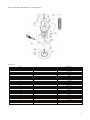
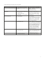
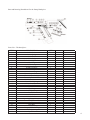
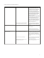
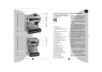
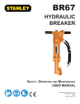
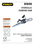
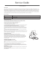
Service Guide
Grease pump Kit
Description
The Champion product grease kit is a manually operated, spring powered grease kit that comes complete with a hand piece. It is
designed to fit a 2.5kg grease pail. The hand piece for the product, once loaded, is capable of approximately 30 high pressure shots
before needing to be reprimed. The high pressure/high volume option facilitates quick and easy greasing with grease pressures of
10,000psi and dispensing quantities of up to 1.25 grams per stroke possible. Suitable for use with greases up to NLGI2, the light
weight, rugged and portable unit makes light work of arduous greasing applications. The Champion product is the ideal greasing
tool for people looking to minimize the time and effort required to grease their vehicles or machinery.
Specifications
Uses
Discharge Quantity
Size
Pressures
Light and self collapsing grease
Once loaded, approximately 30 shots – up to 1.25 grams of grease per shot
2.5kg grease pails
Up to 10,000psi
Important Please Note
Our Champion product 2.5kg grease kit is designed for use with most greases, however,
trouble free greasing is assured with the use of greases up to No. 2 consistency. That is,
the kit is recommended for use with light and self collapsing greases.
Preparing Your Champion 2.5kg Grease Kit
1 Remove follower plate from the pump tube.
2 Insert follower plate into the grease container as shown with boss facing upwards. Push down
firmly onto the grease until grease emerges through the boss.
3 Push the pump tube through the boss and down until the drum cover sits firmly on rim of
grease container. Hand tighten the 3 thumbscrews evenly under rim of the container.
4 To achieve initial prime, push rod cap down several times by using your hand or foot to start
grease flowing through the grease hose. When the hose is full of grease, the rod cap will stay
down.
5 Squeeze gun handle and hold handle closed to bleed air out of the system. When fully bled,
grease from out of the 2.5kg drum will appear at the coupler.
Note: Grease must travel through entire length of hose to accomplish full bleeding and it may be
necessary to repeat Step 4 a couple of times. If unit fails to prime, bump container base several
times on a solid surface to settle the grease.
Important Please Note
Your Champion product 2.5kg grease kit is now ready for operation.
While greasing, the rod cap will rise slowly. When it is fully up and the hand piece loses
pressure, push the rod cap down once or twice to reprime the system and to enable you to
continue greasing. Each pump prime will provide sufficient grease for up to 30 grease shots.
The hand piece is normally operated on the hi-volume switch position. Should high pressure
be required to help clear a blocked or seized lube point, simply move the button on the
hi-pressure position.
Changing over 2.5kg grease drums
1 Unscrew the 3 thumbscrews.
2 Remove the Champion product from the container.
3 Remove follower plate from the empty 2.5kg grease drum and repeat preparation steps 2, 3
and 4
Before operating your product 2.5kg grease kit, bleed any trapped air from the unit.
To remove trapped air: (Point gun in direction of an empty receptacle)
1 Push pump plunger down a few times to start the grease flowing through the grease hose.
2 Squeeze and hold gun handle in to automatically remove trapped air –repeat 1 and 2 until all
air is removed.
How to clean the strainer
Should the strainer need cleaning, (refer trouble shooting guide, page 3, item C(b)),undo the nut
at the base of the pump spring
with a suitable spanner, remove assembly, lever off strainer cover and clean the appropriate
parts as illustrated.
Parts and Drawing Breakdown For the Pump Kit
Parts List
ITEM
1
2
3
4
5
6
7
8
9
10
11
12
13
14
15
16
17
18
19
20
21
22
23
24
25
26
27
28
DESCRIPTION
Retainer Cap
Washer
Back up washer
Clamp nut
Ball spring
1/2” Ball
O’Ring
Hose
Hose Clamp
O’Ring
Clamp Nut
Sealing Washer
Piston Rod and Cup Assembly
Spirol Pin
Strainer Cover
Strainer
Handle
O’Ring
Lid Base
Thump Screw
Pump Tube
Follower
O’Ring
Ball Retainer
9/16” Ball
Footvalve
Piston Rod and Cap Assembly
Pump Spring
2
Trouble Shooting For the pump Kit of the product
PROBLEM
Rod cap rises slowly when the hand piece
is not in use (no visible external leakages)
CAUSE
(a) dirt trapped between inlet ball (26)
and piston
(b) piston O’Ring (25) defective or worn
SOLUTION
(a) unscrew clamp nut (7) and withdraw
assembly. Clean ball (26) and piston (10)
thoroughly. Reassemble
(b) replace piston O’Ring .
Rod cap springs up and the unit will not
pump grease
(a) air lock in grease caused by dent in
container stops follower damaged O’Ring
(21) in follower (20)
(b) grease container empty
(c) footvalve assy (19) faulty, holding
ball (18) off seat
(a) grade of grease too heavy
(b) strainer blocked
(a) remove dents or tilt follower plate
(20) under dent. Replace O’Ring (21) in
follower plate (20). Change over to new
container or refill with grease. Replace
with new assy 17-18-19 do not attempt
to rework this part.
(a) Use No. 2 grade of grease, or lighter.
Force out old grease.
(b) Unscrew clamp nut (7) and withdraw
assembly. Using a screwdriver, lever off
the strainer cover (11). Clean or replace
the strainer (13). see general instructions
below for cleaning technique.
Unscrew clamp nut (7) and withdraw
assembly. Hold piston (10) and loosen the
nut (27). Remove the pin (9) and withdraw
the piston (10). Ease spring tension on the
nut (27) by pushing against spring (92) on
clamp nut (7) and carefully undo nut (27).
Replace O’Ring (96) and back up washer
(5). Order (5). When re-assembling
support piston (10) when driving pin (9)
home, please ensure that the flat end of
spring (2) fits in the cap (1).
(a) Unscrew clamp nut (7) and withdraw
assembly. Using screwdriver, lever off
strainer cover (11) replace O’Ring Order
(14)
(b) Replace drum cover base (15).
(a) Undo and clean surfaces
(b) Replace seal washer. Order (8).
Rod cap stays down. The 2.5kg grease
kit will not pump grease
Grease leaks at top of clamp nut (7)
Gland O’Ring (96) and back up washer
(5) are defective or worn
Grease leaks at bottom of strainer cover
(11)
(a) O’Ring (14) damaged
(b) Spot welds broken
Grease leaks from under clamp nut (7)
(a) Dirt under clamp nut (7)
(b) Damaged seal washer (8)
NSW
3
Parts and Drawing Breakdown For the Pump Hand piece
Parts List – The hand piece
ITEM
1
2
3
4
5
6
7
8
9
10
11
12
13
14
15
16
17
18
19
20
21
22
23
24
25
26
27
28
29
30
31
32
DESCRIPTION
Outlet Screw
Outlet Spring
Outlet Ball
Outlet Body
Teflon Back Up Washer
Glyd Ring
Piston O-ring
Hand piece Casting
Rigid Extension
Grease Coupler
Retainer O-ring
Hose Adaptor Washer
Hose Adaptor O-ring
Hose Adaptor Ball End
Ball Socket Retainer
Inlet Check Spring
Valve Stem Piston
Piston Ball
Piston
Glyd Ring
Seal Body O-ring
Handle Pin
Handle
Valve Inlet Seat
Operating Plunger Control
Control Body Assembly
Inlet Spring
Inlet Ball
Seal Body O-ring
Plunger Control O-ring
Seal Body O-ring
Cap Socket
QTY
1
1
1
1
1
1
1
1
1
1
1
1
1
1
1
1
1
1
1
1
1
1
1
1
1
1
1
1
1
1
1
2
4
Trouble shooting for the product Hand Piece
PROBLEM
The 2.5kg grease kit coupler leaks
Hand piece leaks at the back end of the piston
CAUSE
(a) There is dirt under the seat of the outer ball (3)
SOLUTION
(a) Set the hand piece to the high volume
setting and strike handle sharply. If the
coupler still leaks, remove the rigid extension
(9), spring keeper screw (21), spring (22) and
outer ball (23). Clear the seat and partly
replace the ball, screw and spring keeper
screw. Prime the pump completely to ensure
the maximum possible supply of grease to the
hand piece and tighten up the spring keeper
screw until the grease begins to stop leaking.
Then tighten the spring keeper in an extra two
full turns. Finally, reassemble the rigid
extension to the hand piece.
IMPORTANT: Please note that if you tighten
up the spring keeper screw too much, the hand
piece will become difficult to operate. Too
few turns will allow the hand piece to leak.
If the coupler still leaks, replace the outlet
body (4). When refitting the outlet body to the
handle, ensure that the handle is held in the
closed position. Doing so enables the back up
washers (5 & 7) and o’ring seals to seat
squarely on to the piston (19).
(b) The valve stem (17), has worked itself loose
and is holding the outlet ball (3), off its seat.
(b) Remove the handle (23) by withdrawing
the handle pin (22). Remove the piston (19),
retighten the valve stem (17) or replace with
spare part.
Remove handle (22) by withdrawing handle
pin (22). Remove the piston (19) and replace
with the spare part.
The glyd ring (20) is worn
IMPORTANT: If any signs of wear are
visible on the piston, replace with the spare
part will also be required to solve this problem.
The hand piece fails to deliver grease when on
the high pressure setting
NSW
TEL: (02) 9939 0711
QLD/PNG
TEL: (07) 3889 8480
(a) There is dirt under the delivery ball (18) or
there is a damaged ball seat in the piston (19)
(a) Change the setting to “high volume” and
hit the handle (23) hard to shift the dirt off the
seat. If leaks are still occurring, remove the
handle (23) by withdrawing handle pin (22),
spring (16) and ball (18). Clean the ball and
seat if the problem continues, order and install
spare part .
(b) Seals are worn (25), (26) and (27).
(b) Use spare part and (b) Use spare part and
replace seals in the following order – washer
(5), O’ring (6) and washer (7).
(c) Valve inlet stem (17) has become loose or
dislodged from the piston (19).
(c) Refer to the 2.5kg grease kits coupler leaks
section to referencing section (b).
VIC/TAS
TEL: (03) 8787 8288
WA
TEL: (08) 9209 3066
SA/NT
TEL: (08) 8241 7111
NZ
TEL: (09) 447 1007
FAX: (09) 447 1008
5
PROBLEM
The hand piece fails to deliver grease when on
the high volume setting
CAUSE
(a) There is dirt on the valve inlet seat (24).
SOLUTION
(a) IMPORTANT: This problem will result in
a decreased volume of grease being dispensed
per shot.
Remove control body (26) and tap out valve
inlet seat (24), O’ Ring (31), ball (30) and
spring (27). Clean the ball and seat and
replace in the following order – spring, ball,
O’Ring, valve seal and control body.
(b) Operating plunger control (25) sticking in
control body assembly (26).
(b) Replace the control body assembly (26).
Control push rod in the control body leaks
O’Ring (31) is worn
Hand piece leaks at the grease swivel
Worn seals (11) & (12)
Remove control body assembly (26) from the
hand piece. Also remove the operating control
plunger (25) from the control body and replace
with spare part kit.
Unscrew ball socket retainer (15), push the
seals out and use spare part kit . Be careful to
replace the components in the following
order – O’Ring (13) and washer (12). Locate
O’Ring (11) on to the hand piece casting (8).
Reassemble ball
When on the high volume setting, the hand
piece is too slow and too hard to operate
(a) Spring (16) may have weakened or collapsed
and are blocking the flow of grease
(a) Replace spring (16) and use spare part kit
and valve stem spare part kit.
(b) The grade of grease being used is too heavy.
(b) Change to an NLGI2 or lower viscosity
grease.
(c) Too much comprehension on the outlet
spring (2).
(c) Reset the spring keeper screw as noted in
the 2.5kg grease kits coupler leaks section. If
the problem persists, you will need to replace
the outlet body assembly.
GENERAL INSTRUCTIONS
ALWAYS When the gun has been serviced and the trouble found to be caused by dirt in the valves, the pump unit should also be
cleaned out thoroughly to eliminate the dirt at its source.
CLEANLINESS Dirt and foreign matter (lint, etc.) can seriously affect operation and machinery. Dismantling and reassembly of
this unit should only be attempted in clean conditions.
6