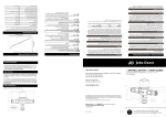
1
Mira 3.0 bar Brass Twin Ended Pump Installation and User Guide THESE INSTRUCTIONS ARE TO BE LEFT WITH THE USER 1 CONTENTS IMPORTANT SAFETY INFORMATION..................................................... 3 WARNING!............................................................................................ 3 CAUTION!............................................................................................. 4 INTRODUCTION........................................................................................ 4 DESCRIPTION........................................................................................... 5 APPLICATION........................................................................................... 5 Storage.................................................................................................. 5 Guarantee............................................................................................. 5 PACK CONTENTS..................................................................................... 6 Documentation...................................................................................... 6 DIMENSIONS............................................................................................. 7 SPECIFICATIONS..................................................................................... 8 INSTALLATION........................................................................................ 10 Pump Location.................................................................................... 10 Plumbing - push-in connectors............................................................ 15 Fitting the Hose to the Pump and Pipework........................................ 15 Plumbing Connections.................................................................. 17 Electrical.............................................................................................. 18 Electrical Connection.................................................................... 18 Connecting the Supply Lead......................................................... 18 Earthing......................................................................................... 19 COMMISSIONING................................................................................... 20 FAULT DIAGNOSIS................................................................................. 21 MAINTENANCE....................................................................................... 24 General............................................................................................... 24 Inlet Filters........................................................................................... 24 Flow Switch Test.................................................................................. 25 Cleaners, Disinfectants and Descalents............................................. 25 SPARE PARTS........................................................................................ 26 DECLARATION OF CONFORMITY........................................................ 27 CUSTOMER SERVICE........................................................BACK COVER 2 IMPORTANT SAFETY INFORMATION WARNING! 1. 2. 3. 4. 5. 6. 7. 8. 9. 10. 11. 12. 13. 14. 15. 16. 17. Products manufactured by us are safe and risk free, provided that they are installed, used and maintained in good working order, in accordance with our instructions and recommendations. Children should be supervised to make sure that they do not play with the appliance. This appliance is not intended for use by persons (including children) with reduced physical, sensory or mental capabilities, or lack of experience and knowledge, unless they have been given supervision or instruction concerning the use of the appliance by a person responsible for their safety. Isolate the electrical and water supplies before commencing installation. The electricity must be turned off at the mains and the appropriate circuit fuse removed, if applicable. THIS APPLIANCE MUST BE EARTHED. MAKE SURE SUPPLEMENTARY BONDING COMPLIES WITH THE "REQUIREMENTS FOR ELECTRICAL INSTALLATIONS" BS 7671. This appliance is intended to be permanently connected to the fixed electrical wiring of the mains system. This appliance must be provided with means for disconnection that is incorporated into the fixed wiring in accordance with the relevant local wiring regulations. A separate, permanently connected supply to the appliance must be through a double-pole switch, which has at least 3 mm contact separation. Make sure all electrical connections are tight, to prevent overheating. DO NOT switch on the electrical supply until the plumbing has been completed. DO NOT switch on if there is a possibility that the water in the appliance is frozen. Allow the appliance to thaw and check for leaks before using. DO NOT operate this appliance if water leaks from the unit. Mains connections are exposed when the cover is removed. Isolate the electrical supply before removing the cover. In the interests of electrical safety, a 30 mA Residual Current Device (RCD) is recommended as part of the electrical circuit. This may be part of the consumer unit or a separate unit. The supply cable is not designed to be replaced. If the supply cable is damaged contact Mira Customer Services department for guidance. If any of the following conditions occur, isolate the electricity and water supplies and refer to "To Contact Us", on the back cover of this guide: 17.1 If the cover is not correctly fitted and water has entered the electrical control case. 17.2. If the pump body or electrical cover is damaged. 3 17.3. If the appliance begins to make an odd noise, smell or smoke. 17.4. If the appliance shows signs of a distinct change in performance, indicating a need for maintenance. 17.5. If the appliance is frozen. CAUTION! 1. 2. 3. 4. 5. 6. 7. 8. 9. 10. 11. 12. Read all of these instructions and retain this guide for later use. Follow all warnings, cautions and instructions contained on the appliance. DO NOT fit the appliance where it may be exposed to freezing conditions. The appliance is not suitable for areas with high humidity (i.e. steam rooms). The electrical installation must comply to "BS 7671 (commonly referred to as the IEE Wiring Regulations) and all relevant building regulations, or any particular regulations or practices specified by the local electricity supply company. The plumbing installation must comply with all national or local water regulations and all relevant building regulations, or any particular regulation or practice specified by the local water supply company. To avoid damage to the appliance when soldered fittings are used, pre solder the pipework and fittings before connecting them to the flexible hoses. To make sure the appliance and supplied fittings are not put under strain during installation, always provide mechanical support when making plumbing connections. Upon completion of the installation, make sure the connections are not under any stress due to misaligned pipework or electrical cables. DO NOT commission this appliance if water leaks from the pump or flexible hoses. DO NOT run the pump dry. There are no serviceable components beneath the cover of the appliance. Only a competent tradesperson should remove the cover. When this appliance has reached the end of its serviceable life, it should be disposed of in a safe manner, in accordance with current local authority recycling, or waste disposal policy. INTRODUCTION Thank you for purchasing a quality Mira product. To enjoy the full potential of your new product, please take time to read this guide thoroughly, having done so, keep it safe for future reference. 4 DESCRIPTION Mira 3.0 bar Brass Twin Ended Pump An electric motor driven twin ended peripheral pump complete with an automatic control system, consisting of flow switches and electronic controls. APPLICATION Mira shower pumps are designed for pressure boosting applications in vented stored water systems, inlet pressures to the pump and ambient temperatures must not exceed the values given in the technical specifications. (See "SPECIFICATIONS".) Storage If the pump is not to be installed immediately on receipt, make sure that it is stored in a dry, frost free and vibration free environment in its original packaging. Guarantee For domestic installations, Mira Showers guarantee the Mira 3.0 bar Brass Twin Ended Pump against any defect in materials or workmanship for a period of three years from the date of purchase. For non-domestic installations, Mira Showers guarantee the Mira 3.0 bar Brass Twin Ended Pump against any defect in materials or workmanship for a period of three years from the date of purchase. For Terms and Conditions refer to the back cover of this guide. Recommended Usage Domestic ü Light Commercial ü Heavy Commercial û Healthcare û If you experience any difficulty with the installation or operation of your new appliance, then please refer to "FAULT DIAGNOSIS", before contacting Mira Showers. Our contact details can be found on the back cover of this guide. 5 PACK CONTENTS Check the contents of the pack and tick the appropriate boxes to familiarise yourself with the part names and to confirm that all parts are included. Electrical Supply Lead Documentation 1 x Installation and User Guide 1 x Customer Support Brochure 6 1 x Mira 3 bar Brass Twin Ended Pump 4 x Flexible Hoses DIMENSIONS 296 122 183 215 Electrical Supply Lead 1500 mm (1.5 m) 132 All dimensions are nominal and in millimetres Fig. 1 7 SPECIFICATIONS Pressures Minimum Inlet Pressure 5 kPa (0.05 bar) = 0.5 m Maximum Static Pressure 140 kPa (1.4 bar) = 14 m Supply Pressure Differential Nominally Equal Temperatures Maximum Water Temperature * 65 °C Minimum Water Temperature 4 °C Maximum Ambient Temperature 40 °C Electrical Power Supply (Volts/phase frequency) 230 V / 50 Hz Protection Rating IPX2 Type of Motor Induction Power Consumption 650 W Full Load Current 2.9 A Rating Continuously rated. * In normal circumstances the temperature of stored water should never exceed 65 °C. A stored water temperature of 60 °C is considered sufficient to meet all normal requirements and will minimize the build up of scale in hard water areas. Note: These specifications are to be used in conjunction with the rating label attached to the pump. 8 4.0 30 3.0 20 2.0 10 1.0 0 0.0 FLOW (l/min) Mira 3.0 bar Brass Twin Ended Pump Performance Graph 9 HEAD (bar) HEAD (Metres) 40 INSTALLATION Key to symbols used in the system layouts: Servicing Valve Check Valve Mixing Valve Pressure Switch Float Type Automatic Air Vent (Bottle Valve) Pressure Accumulator Float Operated Valve Shower Handset Fixed Shower Head DHW Domestic Hot Water 15 mm Diameter Pipe 22 mm Diameter Pipe Installation must be carried out in accordance with these instructions, and must be conducted by designated, qualified and competent personnel. Pump Location 1. 2. 3. 4. 5. 6. The preferred pump location is at floor level next to the hot water cylinder or a level that is below the secondary tapping that feeds the pump. This will ensure access to an air free water supply which is important for the pump to operate reliably. (See Fig. 2.) The pump must NOT be located where the static inlet pressure is greater than permitted and within the values given. (See Fig 3 & 4 and 'SPECIFICATIONS' or rating label attached to the pump.) Water pumps can develop leaks and should, therefore, not be located where seepage may go undetected or cause damage. The pump must be installed such that it is accessible for servicing or removal. When servicing or disconnecting, small amounts of water may drain from the unit and pipework. Take care to protect the pump from frost and freezing, particularly when located in an unheated area. Make sure adequate ventilation is provided (minimum clearance of 80 mm around all sides of the pump). The pump should be installed in a low dust area. The motor casing can become very hot under normal operating conditions. Make sure the pump cannot be touched during operation. If 10 installed in an airing cupboard, make sure no fabrics come in contact with the pump. 7. 8. 9. 10. Location must be DRY and FROST FREE and NOT EXPOSED TO WATER SPRAY. The pump must be sited as low and as close as possible in relation to the water source and mounted in a horizontal position with the outlet connection vertically upwards. The operation of the flow switch will be impaired in any other position. Do not rigidly secure the pump to the mounting surface. The pump must have a minimum flooded suction head of 0.5 metres at all times. The pump must be installed in a positive head position, a gravity flow of approximately 1.0 l/min is required from the highest outlet. This is normally achieved with a static head of 100 mm from the base of the header tank to the highest position of the shower fitting. (See Fig. 2.) Warning Pipe (Overflow) Minimum 1.5 m with other simultaneous hot water services Cistern Minimum 100 mm 25 mm DHW Cylinder Feed Cold Feed to Mixing Valve 90° DHW 30 to 60° Air Separation Connections Pump Electrical Supply Lead (1.5 m) Other Hot Water Services System Layout for Mira Shower Pump Fig. 2 11 Max. Inlet Head = 14 m Min. Inlet Head = 0.5 m Cistern Mixing Valve DHW Pump System Layout for Mira Shower Pump Fig. 3 Max. Inlet Head = 14 m Min. Inlet Head = 0.5 m Cistern Pump DHW Mixing Valve System Layout for Mira Shower Pump Fig. 4 12 Cistern Pump Mixing Valve DHW Unsuitable Layout for Mira Enduro Pump Fig. 5 Cistern Mixing Valve DHW Pump Unsuitable Layout for Mira Enduro Pump Fig. 6 13 Cistern Pump Mixing Valve DHW Unsuitable Layout for Mira Enduro Pump Fig. 7 11. 12. 13. 14. 15. 16. 17. 18. The anti-vibration mounting feet and flexible hoses are supplied to reduce noise transmission, the flexible hoses supplied may be bent to an angle of 30º Max. (See Fig 10.) Make sure that any noise is not amplified through loose panels, pipework or other fixtures and fittings in close proximity. Either end of the pump is suitable for hot or cold water. Do not fit a non-return valve in suction line (inlet) pipework to the pump. The pump must be free to vent to the supply tanks at all times. Avoid long pipe-runs and make sure pipework is adequately sized for the minimum flow demand. Pipework configurations which can allow air locks to form should be avoided. For inlet pipework, this should be achieved by utilising pipe-runs with a continuous fall. For outlet pipework, either provide a continuously rising pipe‑run, or if an "up and over" pipe-run is unavoidable, fit a float type automatic air vent at the highest point as shown (See Fig 3 & 4). The hot feed from the cylinder must be as illustrated in Fig 2. Side entry cylinder bosses are not recommended. A drop in cylinder water level could expose a top entry immersion element. Air in water gathers at the edge of the cylinder, and in the centre, during the heating process, before travelling up the vent. Care should be taken when using soldering flux. Protect the pump from damage whilst making soldered connections as some fluxes cause damage to plastic components. All connection pipework must be adequately supported. 14 19. Do not rigidly secure pump unit to the mounting surface. Plumbing - push-in connectors 1. 2. 3. 4. Do not use stainless steel, chrome or nickel plated pipe with the flexible hose push-in plumbing connections. Do not introduce solder flux into the joint or surrounding area as connectors will be attacked and may fail. All solder joints should be completed and flux residues removed before final connection to push-in connections, on the flexible hose. Do not allow contact with oil or cellulose based paints, paint thinners or strippers, acid based descalents or aggressive cleaning agents. Flush all pipework thoroughly before connecting to the pump. Fitting the Hose to the Pump and Pipework The hoses are fitted with plastic push-in connectors, which must only be connected with the following: a) 22 mm diameter copper pipe to BS EN 1057 - R250 (half hard) - Table 3. b) 22 mm plastic pipe to BS 7291 part 1 and part 2 (Table 1), or part 3 (Table 1) plus internal support sleeve*. c) Appropriate plumbing fitting that provides a leak tight connection. * The internal bore of the plastic pipe must be supported against collapse with the pipe manufacturer's recommended support sleeve (pipe insert). 5. Make sure the pipe is free from all scoring marks and deformities in the area of the insertion depth (Fig. 8) and cut the pipe square, removing all burrs and sharp edges to prevent damage to the sealing 'O'-ring. 6. Prior to inserting the pipe, mark the insert depth with a soft pencil at a distance of 31 mm from the end to be inserted (Fig. 8). 7. Check in the mouth of the fitting that the 'O'-ring, nylon washer and collet are in position as shown (Fig. 8). 8. Push the pipe firmly into the fitting, until the pencil mark is level with the top of the collet. At the same time the pipe should hit the internal stop inside the fitting. 9. To release the joint, push pipe firmly into the fitting, hold the collet down and gently remove the pipe. If the system has been filled with water, care should be taken to isolate the pump and towels used to absorb any spilled water. 10. The inlet and outlet ports to the pump have pre-assembled fittings specifically designed for connection to the push fit hoses supplied. Position the hose over the fitting and push down firmly until the pipe stop resistance is felt. Pull back on the hose to check it is secure and correctly fitted. 15 22 mm Pipe Insertion Depth 33 mm Pencil Mark Nylon Washer Collet 'O' Seal Pipe Stop Hose Fig. 8 16 Plumbing Connections 22 mm PIPE OPEN CLOSED 30º Max ISOLATING VALVE FLEXIBLE HOSES (Do not kink or twist) INLET FILTERS FLOW SWITCH PUMP BODY ANTI-VIBRATION FOOT Fig. 9 17 Electrical Electrical Connection The pump is provided with a factory fitted supply cord. This must be permanently connected to the fixed wiring of the mains supply. Means of disconnection must be incorporated in the fixed wiring in accordance with the current electrical wiring regulations. A double poled switched, fuse connection unit is suitable for this purpose. This switch must comply with BS1363-4, protected with a 5 Amp fuse and should be mounted in an easily accessible position. The switch should also be labelled, particularly when located near to any other electrical isolating switches. 1. The electrical installation must comply to "BS 7671 (commonly referred to as the IEE Wiring Regulations) and all relevant building regulations, or any particular regulations or practices specified by the local electricity supply company. The installation must be carried out by a competent person. 2. In the interests of electrical safety, a 30 mA Residual Current Device (RCD) must be installed in the supply circuit. This may be part of the consumer unit or a separate unit. 3. Before starting work on the electrical installation, make sure the power supply is isolated. 4. This appliance must be earthed. 5. The motor and wiring must not be exposed to water. 6. Do not allow the supply cord to come in contact with any hot surfaces, including the motor housing, pump body or pipework. The cord should be safely routed and secured with suitable cable clips. Connecting the Supply Lead 7. The wires in the supply lead are coloured in accordance with the following code: GREEN/YELLOW = EARTH ( ) BLUE = NEUTRAL (N) BROWN = LIVE (L) 8. Make sure all electrical connections are tight, to prevent overheating. 18 Earthing 9. 10. 11. This appliance must be earthed via the supply cord, which must be correctly connected to the earth point located in the terminal box. Copper or metallic pipework must have supplementary earth bonding where the continuity has been broken by flexible hoses or plastic components. Adjacent suction and delivery pipes should be fitted with earthing clamps to BS 951 and connected with earthing wire size 4 mm² (Fig. 10). Certain installations may require additional earthing arrangements such as equipotential bonding. Reference should be made to the relevant regulations concerning this subject to make sure of compliance. 19 Fig. 10 COMMISSIONING Commissioning must be carried out in accordance with these instructions, and must be conducted by designated, qualified and competent personnel. 1. The motor casing can become very hot under normal operating conditions, care should be taken to make sure it cannot be touched during operation. 2. The pump chamber must be full of water at all times. Seal damage will result if the pump is allowed to run dry. 3. Do not operate the pump with any of the pump inlet and outlet isolating valves in the "OFF" position. Damage to the pump will result. Before commissioning the pump, make sure the following points have been observed in the installation: • • • 4. 5. 6. 7. 8. 9. he plumbing system that feeds the pump has been flushed T thoroughly. There is always enough stored water to meet the demand. The minimum flow rate required to operate the pump is always present. (1 litre/min from the highest outlet.) With the electrical supply isolated, prime the pump by turning on the water supply. Vent the pump by opening an outlet (e.g. shower control). The pump will fill with water, check for any leaks around the pump and hose connections. The pump is primed when water runs from the outlet at gravity pressure. Keeping the outlet open, switch on the power supply to the pump. Pump will start automatically, allow to run until all the air is purged from the outlet. Check the pump, hoses and pipework for leaks. Turn off the outlet, the pump will automatically stop. Operate the outlet to test that the pump starts and stops automatically. Check for further leaks when the pump is both running and stationary. If the pump does not operate, repeat the commissioning procedure and refer to section "Fault Diagnosis". 20 FAULT DIAGNOSIS Symptom Cause Rectification 1. Pump does not (a) No power supply. 1. Check all fuses and RCD. Make start. sure power supply is available at the double pole isolator switch. If fuse "blows" repeatedly, contact Mira Customer Service Dept. Details on the back cover of this guide. (b) No/low flow 1. Clean the shower head and make through outlet sure the flow controls are operating (tap/shower) correctly. 2. Check and clean the inlet filters (pump and tap/shower). Refer to section "Maintenance". 3. Check the system for air locks and recommission the pump, refer to section "Commissioning". 4. Check the isolating valves are fully open and other restrictions. 5. Check the system has adequate flow rate for the pump to operate, refer to section "Installation". 6. The flow switch mechanism is sticking. See "Flow Switch Test". (c) Internal problem. 1. Contact Mira Customer Service Dept. Details on the back cover of this guide. The pump has (d) Motor thermal 1. Allow the motor to cool, up to 1 hour, started but switch tripped. refer to symptom 5 (c). stopped within a short period. 2. The pump (a) Flow-switch 1. Air pocket after pump. Make operates operating due to sure plumbing complies with momentarily water movement recommended layout (Fig. 2, 3 & 4). when not in pipework. 2. Air pocket in the pump supply (hot) required. expanding due to system heating. Correct the pipework layout to eliminate thermal expansion, fit a single check valve close to and AFTER PUMP OUTLET, refer to "Note Regarding Check Valves" at end of this section. 21 Symptom 3. Pumped flow/ pressure is initially adequate, but reduces after short time. Cause (a) Water supply fault. 1. 2. 3. 4. 5. 4. The pump is noisy in operation. (b) Outlet Fitting. 1. (a) Installation fault. 1. Note! All pumps generate some noise. Installation conditions may allow this to be amplified. 2. (b) Pump internal mechanism. 1. 2. 3. 5. The pump switches off while in use. (a) Power supply fault. 1. (b) Water supply fault. 1. 22 Rectification Check that hot and cold water storage volumes are sufficient for demand. Clean the shower head. Check that all inlet filters (pump and shower/tap) are clean. Refer to section "Maintenance" and relevant outlet manufacturer's installation instructions. There is a blockage in the plumbing system. Isolate the pump before removing the blockage. Pipework configuration and/or water supply conditions are causing air induction. Make sure plumbing complies with recommended layout (Fig. 2, 3 & 4). Check for blockages (tap washers, shower hose/head, etc...). Vibration from the pump body transmitted through reverberant material. Check the pump position and pipework fixings. Note! The pump should be free standing on its rubber feet, and not screwed down. Fit the flexible hoses supplied. Fault in the supply to the pump, refer to Symptom 3 (a). Check for debris and/or damage in impeller housing. Mechanical seal worn/damaged. Replace. Pump motor fault. Contact Mira Showers (see back cover) to arrange service visit. Check all fuses and RCD. Make sure the power supply is available at the pump terminal box. Check the hot and cold water storage volumes are sufficient for the demand. (continued...) Symptom Cause (c) Outlet Fitting. 1. (d) Pump motor thermal switch tripped 1. 2. 3. 4. 6. Leak from the (a) Seal worn/ pump housing. damaged. 1. Rectification Check for blockages (tap washers, shower hose/head, etc...). Allow the motor to cool, up to 1 hour. Check the ambient air temperature around the pump does not exceed 40 oC. Make sure adequate free ventilation is provided (minimum clearance of 80 mm around all sides of the pump). Pump impeded internally, refer to symptom 4(b). Contact Mira Customer Service Dept. Details on the back cover of this guide. Note Regarding Check Valves. Fitting a check valve is a secondary measure, initially the cause of water surge should be investigated and rectified. The single check valve should be of spring‑loaded pattern and fitted in the discharge pipework. This may increase the minimum head pressure required to operate the flow-switch. 23 MAINTENANCE General Mira products are precision-engineered and should give continued superior and safe performance. Providing that the pump has been correctly installed and operated as advised in this booklet, difficulties should not arise. 1. Isolate and drain the water supply to the pump if it is to be left for a prolonged period during which there is a possibility of freezing (e.g. winter holiday). 2. The pump should not be left unused for extended periods of time after being installed. Run the pump with cool water for at least 5 minutes every 4 weeks to prevent scale build up from seizing the internal mechanism. This particularly applies to locations of infrequent use (e.g. guest bathrooms). Inlet Filters 3. 4. 5. 6. 7. 8. Isolate the electrical supply to the pump. Release the water pressure by opening an outlet. Isolate the water supply to both the inlets and outlets. Disconnect the flexible hoses at the pump inlets. To release the joint, push pipe firmly into the fitting, hold the collet down and gently remove the pipe. Use towels to absorb any spilled water. Carefully remove and clean the Filters. Reassemble making sure they are level with the top of the inlet. Reassemble the flexible hoses. Position the hose over the fitting and push down firmly until the pipe stop resistance is felt. Pull back on the hose to check it is secure and correctly fitted. Nylon Washer Collet 'O' Seal Filter Pipe Stop Hose Fig. 11 24 Flow Switch Test 9. 10. 11. 12. First confirm that the flow switch reed clamps have not been dislodged during handling or installation. The clamps must be fully located within the groove as shown (Fig. 12). Obtain a magnet. (A typical fridge magnet is suitable.) Make sure the power supply is switched ON. Position the magnet directly in front of the reed clamp as shown (Fig. 12). If pump does not start, then slowly move the magnet up and down to a position past the top of the reed clamp. The pump should start instantaneously at some point while the magnet is moving. If the pump does not start then there is a possible fault with the reed switch or the electronic control PCB located within the pump. These should be checked electrically by a competent tradesperson or contact Mira Showers to arrange for a service engineer to diagnose the fault. Reed Clamp Groove Fig. 12 Cleaners, Disinfectants and Descalents Caution! On installations where chemical disinfectants or descalents are periodically used, the effect to the pump of any chemical solution produced either directly or as a by-product must be considered. Acid based descalents and aggressive cleaning agents must not come into contact with the pump. The pump must be removed from the system prior to use of such products. The system should be flushed to remove all chemicals before the pump is reconnected. If there is any doubt as to the suitability of the chemical solution then please contact the manufacturer of the cleaning product for advice prior to use. 25 SPARE PARTS Spare Parts List 465.01 465.02 465.06 465.08 465.09 872.56 1587.002 1745.005 1745.006 'O' Seal Pack - including Mechanical Seal (components identified 'A') Flow Switch Module (includes cable tie) Screw Pack Impeller Assembly Push Fit Pack (for flexible hose, not illustrated) Cable Tie Motor Control PCB (not illustrated) Flow Switch Mechanism (includes cable tie) Flexible Hose Assembly Spare Parts Diagram A 465.06 (x4 supplied) A 1745.005 1745.006 465.02 A 465.03 465.08 872.56 A 465.08 A 465.06 (x4 supplied) 26 DECLARATION OF CONFORMITY DECLARATION OF CONFORMITY 2006/42/EC BS EN ISO 12100-1, BS EN ISO 12100-2, BS EN 809 2006/95/EC BS EN 60335-1, BS EN 60335-2-41, EN 50366 2004/108/EC BS EN 55014-1, BS EN 55014-2, BS EN 55022, BS EN 61000-3-2, BS EN 61000-3-3, BS EN 61000-4-2, BS EN 61000-4-3, BS EN 61000-4-4, BS EN 61000-4-5, BS EN 61000-4-6, BS EN 61000-4-11 IT IS HEREBY CERTIFIED THAT THE STUART ELECTRIC MOTOR DRIVEN PUMP AS SERIAL NUMBER BELOW, COMPLIES WITH THE ESSENTIAL REQUIREMENTS OF THE ABOVE E.E.C. DIRECTIVES. RESPONSIBLE PERSON AND MANUFACTURER STUART TURNER LIMITED HENLEY-ON-THAMES, OXFORDSHIRE RG9 2AD ENGLAND. Signed. . . . . . . . . . . . . . . . . . . . . . . . . . . . . . . . . . . . . . . . . Customer Relationship Manager Stuart Turner are an approved company to BS EN ISO 9001:2000 Manufactured on behalf of Kohler Mira by Stuart Turner Ltd, Henley-on-Thames, Oxfordshire RG9 2AD 27 CUSTOMER SERVICE Guarantee Helpdesk Service Your product has the benefit of our manufacturer’s guarantee which starts from the date of purchase. To activate this guarantee, please return your completed registration card, visit our website or free phone 0800 0731248 within 30 days of purchase (UK only). Within the guarantee period we will resolve defects in materials or workmanship, free of charge, by repairing or replacing parts or product as we may choose. This guarantee is in addition to your statutory rights and is subject to the following conditions: ● The guarantee applies solely to the original installation under normal use and to the original purchaser only. The product must be installed and maintained in accordance with the instructions given in this user guide. ● Servicing must only be undertaken by us or our appointed representative. Note! if a service visit is required the product must be fully installed and connected to services. ● Repair under this guarantee does not extend the original expiry date. The guarantee on any replacement parts or product ends at the original expiry date. ● For shower fittings or consumable items we reserve the right to supply replacement parts only. The guarantee does not cover: ● Call out charges for non product faults (such as damage or performance issues arising from incorrect installation, improper use, lack of maintenance, build up of limescale, frost damage, corrosion, system debris or blocked filters) or where no fault has been found with the product. ● Water or electrical supply, waste and isolation issues. ● Compensation for loss of use of the product or consequential loss of any kind. ● Damage or defects caused if the product is repaired or modified by persons not authorised by us or our appointed representative. ● Routine maintenance or replacement parts to comply with the requirements of the TMV 2 or TMV 3 healthcare schemes. ● Products purchased ex-showroom display. Our Customer Services Team is comprehensively trained and can offer help and advice, spare parts, accessories or a service visit. We will need you to have your model name or number, power rating (if applicable) and date of purchase. As part of our quality and training programme calls may be recorded or monitored. Mira Showers Website (www.mirashowers.co.uk) From our website you can register your guarantee, download additional user guides, diagnose faults, purchase our full range of accessories and popular spares, refer to our FAQ’s and request a service visit. What to do if something goes wrong Eire Telephone: 01 459 1344 If your product does not function correctly when you first use it, contact your installer to check that it is installed and commissioned in accordance with the instructions in this guide. If this does not resolve the issue, contact our Customer Services Team who will offer you or your installer help and advice. If you experience problems, check in this manual to see if simple home maintenance is required. If you require further assistance call our Customer Services Team. Spares and Accessories We maintain extensive stocks of genuine spares and accessories and aim to provide support throughout the product’s expected life. Payment can be made by phone at time of order using most major Credit or Debit cards and we aim to despatch orders within 2 working days. Items purchased from us are guaranteed for 12 months from date of purchase. For safety reasons spares exposed to mains voltages should only be fitted by competent persons. Returns – items can be returned within one month of date of purchase, providing that they are in good condition and the packaging is unopened. Please obtain authorisation from our Customer Services Team before return. We reserve the right to apply a 15% restocking charge. Service / Repairs We have a nationwide team of Service Technicians can carry out service or repair work to your product within the guarantee period and beyond. You have the assurance of a fully trained Technician, genuine spare parts and a 12 month guarantee on any chargeable work done. Payment should be made directly to the Service Technician who will accept most major Credit or Debit cards. To Contact Us UK Telephone: 0844 571 5000 E-mail: [email protected] Fax: 01242 282595 By Post: Mira Customer Services Dept, Cromwell Road, Cheltenham, Gloucestershire, GL52 5EP E-mail: [email protected] Fax: Dublin 01 459 2329 By Post: Modern Plant Ltd (Dublin), Otter House, Naas Road, Clondalkin, Dublin 22 Extended Guarantees A selection of protection plans are available that enable you to cover repair bills for the life of your policy (excludes Eire). Ring 01922 471763 for more details. Mira is a registered trade mark of Kohler Mira Limited. The company reserves the right to alter product specifications without notice. 1173255_W2_A (P81E) 1745 ST 19575 1711/1-01 FM 14648 28 © Kohler Mira Limited, May 2011