1
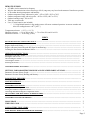
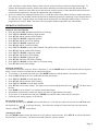
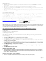
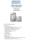
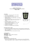
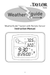
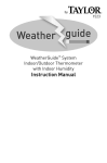
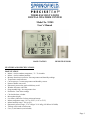
WIRELESS MULTI-ZONE DIGITAL WEATHER CENTER Model No. 91905 User’s Manual BASE STATION REMOTE SENSOR FEATURES AND SPECIFICATIONS BASE STATION Indoor / wireless outdoor temperature, °C / °F selectable Indoor / wireless outdoor humidity Memory function to recall min / max temperature and humidity readings Temperature trend indicators Can accept up to 3 remote temperature and humidity sensors Remote channel auto-scroll Barometric pressure bar graph with history recall Weather forecaster with icons Programmable high / low temperature alert Heat Index / Dew Point readings Clock with alarm, calendar Moon phase display Low battery indicators for base station and remote Indoor temperature range: 14°F to 158°F (-10°C to 70°C) Indoor humidity range: 20% to 95% Barometric pressure range: 27.47 inHg to 31.01 inHg (930 hPa to 1050 hPa) Tabletop easel stand or wall mount Uses (2) AA batteries (not included) Page 1 REMOTE SENSOR 433 MHz wireless transmission frequency Wireless data transmission to base station up to 100 ft. (range may vary based on the amount of interference present) LCD readout showing temperature and humidity Outdoor temperature range without wire probe: -4°F to 158°F (-20°C to 70°C) Outdoor temperature range with wire probe: -40°F to 158°F (-40°C to 70°C) Outdoor humidity range: 20% to 95% Table top or wall mount Uses (2) AAA batteries (not included) o ** Using lithium batteries in the outdoor sensor will ensure continued operation in extreme weather and allow for readings down to -40OF [-40OC] Temperature tolerance: +/- 2°F (+/- 1.1°C) Humidity tolerance: +/- 5% at 30% to 90%; +/- 7% at 20 to 29% and 91 to 95% Barometer tolerance: +/- 0.148 inHg (5 hPa) INDEX BATTERY INSTALLATION AND SETUP………………………………………………………………………… Base Station Battery Installation……………….……………………………………………………………………….. Register the Remote Sensor………………………………….…………………………………………………………. Register a Remote Sensor When the RF Signal is not Showing………………………………………………………... Locating the Base Station and Remote Sensor………………………………………………………………………….. 3 3 3 3 3 OPERATING INSTRUCTIONS …………………………………………………………………………………….. Setting the Clock and Calendar…………………………………………………………………………………………. Setting the Alarm Time ………………………………………………………………………………………………… De-activating the Alarm………………………………………………………………………………………………. Activating the Alarm…………………………………………………………………………………………………... Silencing the Alarm…………………………………………………………………………………………………… 4 4 4 4 4 5 WEATHER FORECAST ICONS…………………………………………………………………………………….. 5 SETTINGS FOR BAROMETRIC PRESSURE AND WEATHER FORECAST ICONS………………………... Barometric Pressure History Graph…………………………………………………………………………………….. Barometric Pressure History Reading and Memory…………………………………………………………………….. 5 5 5 6 BAROMETRIC PRESSURE…………………………………………………………………………………………. 6 MAX/MIN MEMORY………………………………………………………………………………………………… TEMPERATURE ALERTS…………………………………………………………………………………………... Setting the Indoor Temperature Alert ………………………………………………………………………………….. Setting the Outdoor Temperature Alert…………………………………………………………………………………. Activating and Deactivating the Temperature Alerts……………………………...……………………………… HEAT INDEX AND DEW POINT TEMPERATURES…………………………………………………………….. 6 TEMPERATURE TREND ARROWS……………………………………………………………………………….. 7 MOON PHASE ………………………………………………………………………………………………………... TIDE INDICATOR …………………………………………………………………………………………………... 7 7 LOW BATTERY INDICATORS…………………………………………………………………………………….. 7 PURCHASING ADDITIONAL REMOTE SENSORS……………………………………………………………... 7 6 6 6 7 Page 2 BATTERY INSTALLATION AND SETUP Notes: Notes: Always replace all batteries at the same time; do not mix old and new batteries. Do not mix alkaline, standard (carbon-zinc) or rechargeable (ni-cad, ni-mh, etc.) batteries. For maximum performance in normal conditions we recommend using good quality alkaline batteries. When temperatures are near or below freezing (32°F / 0°C), alkaline batteries can lose power resulting in a loss of remote transmission. If you reside in an area that experiences frequent temperatures near or below freezing, we recommend using lithium batteries to minimize the loss of transmission. See additional notes in Locating the Base Station and Remote Sensor below. NOTE: please recycle or dispose of batteries per local regulations. WARNING: Batteries may pose a choking hazard. Do not let children handle batteries. PRECAUTION: Do not dispose of batteries in fire. Batteries may explode or leak. Remove the batteries if the thermometer or remote sensor will not be used for a long period of time. Base Station Battery Installation Remove the printed vinyl label from the LCD screen of the base station Position the remote sensor near the base station Open the battery compartment at the back of the base station and insert (2) AA batteries according to the polarity markings. Replace the battery compartment cover. Within a short time the RF signal icon (located to the left of the outdoor temperature channel indicator) will start flashing. This indicates that the base station is ready to pick up the RF outdoor temperature signal from the remote sensor. It will continue to flash for 3 minutes or until the signal from the remote sensor is detected. Register the Remote Sensor Open the battery compartment at the back of the remote sensor and slide the channel selector switch to your desired channel. For the first remote you may select any channel, for additional remotes select any unused channel Insert (2) AAA batteries according to the polarity markings. Be sure to install the batteries in the remote within the time that the RF signal icon is flashing on the base station. Press the °C/°F button inside the remote sensor battery compartment to display the temperature in °C or °F Replace the battery compartment cover Press the UP/C/F button at the back of the base station to display the temperature in °C or °F If you have registered more than one sensor, press CHANNEL to select the remote channel you want displayed permanently on the base station. Or press CHANNEL until you observe a circular arrow on the base station LCD display under the channel number. The unit will then auto-scroll, continually changing from channel to channel. Occasionally you may experience interference on a particular channel. If your base station has trouble picking up the RF outdoor temperature signal, remove the batteries from the remote sensor, slide the channel selector switch to another channel and re-install the batteries. Note: The TX button inside the remote sensor battery compartment is for factory testing. You will not need to use it. Register a Remote Sensor When the RF Signal Icon is not Showing Press and hold the CHANNEL button for 3-4 seconds until the RF signal icon is showing Install the batteries in the new remote sensor or remove and re-install them if they have already been installed Locating the Base Station and Remote Sensor Choose a suitable place for the base station and remote outdoor sensor, within the transmission distance Place the base unit near a window, but away from direct sunlight or sources of heat or air conditioning to ensure accurate temperature readings. The remote sensor is water resistant, but not waterproof. Locate the sensor out of direct sunlight, in an area where it will not be exposed to rain, snow or ice The location you choose is critical for maximizing the transmission range. The remote sensor is designed to transmit up to 100 ft. unimpeded. Although the RF signal may travel through solid surfaces or objects, transmitting through Page 3 walls, metal doors, metal framed windows, thick concrete, stone or brick may reduce the transmission range. To optimize the transmission distance, the base and remotes should be positioned in locations that minimize these obstructions. Interference from other sources such as home security systems, wireless doorbells and wireless home entertainment equipment may interrupt the transmission signal temporarily. In areas of extreme low temperatures (below 0°F), re-locate the remote sensor indoors and use a remote sensor wire. The sensor wire is not included with the unit and can be purchased separately by contacting Taylor Customer Service at 1-866-843-3905. Plug the sensor wire into the remote and route the wire through a nearby window. Be sure to plug in the wire securely. Note: The sensor wire will transmit outdoor temperature only, not humidity. OPERATING INSTRUCTIONS Setting the Clock and Calendar Press and hold the SET AL button until the hour is flashing. Press UP/C/F or DOWN buttons to adjust the hour Press SET AL and the minutes will be flashing Press UP/C/F or DOWN to adjust the minutes Press SET AL and the year will be flashing Press UP/C/F or DOWN to adjust the year Press SET AL and M / D will be flashing Press UP/C/F or DOWN to select either a Month / Day (M/D) or Day / Month (D/M) calendar format Press SET AL and the month will be flashing Press UP/C/F or DOWN to adjust the month Press SET AL and the day will be flashing Press UP/C/F or DOWN to adjust the day Press SET AL and 12h or 24h will be flashing Press UP/C/F or DOWN to select either 12 or 24 hour timing Press SET AL to lock in the settings Setting the Alarm Time Two different alarm times can be set, Alarm 1 and Alarm 2. Use the MODE button to scroll from normal time display to Alarm 1 (A1) to Alarm 2 (A2) then back to normal time display. To set Alarm 1; In normal time mode, press the MODE button once and the Alarm 1 time and (A1) will show Press the SET AL button for 3-4 seconds until the alarm hour flashes Press UP/C/F or DOWN to set the alarm hour Press SET AL and the minutes will be flashing Press UP/C/F or DOWN to set the alarm minutes Press SET AL to lock in the settings. The alarm is now activated and the alarm bell icon will show next to the time. Press MODE to get to Alarm 2 or to return to normal time display If no buttons are pushed, the normal time display will show in approximately 20 seconds To set Alarm 2; In normal time mode, press MODE twice and the Alarm 2 time and (A2) will show Follow the same setting sequence as for Alarm 1 De-activating the Alarm To de-activate an alarm, press MODE to choose the alarm (A1 or A2) that you want to de-activate. Press SET AL until the alarm bell icon is no longer showing. Your alarm time settings will remain and you can re-activate the alarms by following the instructions below. Activating the Alarm Press the MODE button to choose the alarm (A1 or A2) that you want to activate. Press SET AL to activate (the alarm bell icon and 1 or 2 will show). The alarm will sound at the time you have entered. Page 4 Silencing the Alarm When the alarm sounds press any button on the base station to silence the alert or press SNOOZE to activate the snooze function When snooze is activated the Zz symbol will appear and the alarm will sound again in 5 minutes When the alarm sounds again, press SNOOZE to continue the snooze function or press any button on the base station to discontinue snooze The alarm icon will remain on the display and the alarm will sound every day at the pre-set time until the alarm is deactivated BAROMETRIC PRESSURE The atmospheric pressure is displayed as a numerical value in either inches of mercury (inHg) or hectopascals (hPa). You can choose to display either reading as an ABSOLUTE value or a RELATIVE value; 1) ABSOLUTE air pressure is the true measured air pressure at the current time and location of your weather center. 2) RELATIVE air pressure takes into account your elevation and calculates the value back to sea level. RELATIVE air pressure allows easier comparisons and is the value given by most TV and radio stations. To find the elevation at your location, access the following U.S. Department of the Interior website: http://geonames.usgs.gov/pls/gnispublic/ 1) Enter the Feature Name (city) 2) Enter the State 3) Use the SEND QUERY option Note: If you are going to choose the RELATIVE air pressure option, have your elevation information available when you enter the following settings. It is not necessary to enter your elevation if you choose the ABSOLUTE air pressure option. If you don’t enter an elevation, the default reading will be 0 ft. (sea level) SETTINGS FOR BAROMETRIC PRESSURE AND WEATHER FORECAST ICONS To enter your selections for; 1) inHg or hPa 2) absolute air pressure or relative air pressure 3) calibrating your weather icons Note: When you select inHg, your elevation will be shown in feet (FT). When you select hPa, your elevation will be shown in meters (M). Press and hold HISTORY for 2-3 seconds until inHg or hPa is flashing Press UP/C/F or DOWN to select inHg (inches of mercury) or mb hPa (hectopascals) Press HISTORY and use UP/C/F or DOWN to select ABSOLUTE or RELATIVE pressure (ABS or REL will show to the left of the numerical reading) Press HISTORY and use UP/C/F or DOWN to enter the elevation at your current location (range: -656 to 6,560 FT or -200 to 2,000 M). It is not necessary to enter the elevation if you have chosen the ABSOLUTE air pressure option. Press HISTORY and the weather icons will be flashing Press UP/C/F or DOWN to select the current weather condition in your area (sunny / partly cloudy / cloudy / rain / heavy rain) Press HISTORY to lock in the settings Barometric Pressure History Graph The bar graph on your base station LCD displays barometric pressure history for the prior 12 hours. The column at the right (0) is the current time period. Moving to the left are the prior time periods, beginning with -1 hour, then -2 hours, -3 hours, -6 hours and -12 hours. Barometric Pressure History Reading and Memory Above the bar graph is the current numerical pressure reading in either inHg or hPa. (0 HR) Page 5 To display the numerical pressure reading for prior periods, use the HISTORY button. Press once to view the pressure reading one hour prior (-1), twice to view two hours prior (-2), etc. up to 12 hours prior. WEATHER FORECAST ICONS Based on temperature, humidity and barometric pressure data collected over the previous 12 hours, the base unit predicts weather conditions for the next 12 – 24 hours. One of the following icons will appear on the LCD display; Sunny, Partly Cloudy, Cloudy, Rain, Heavy Rain. Note: By nature, weather forecasts are often not correct. Taylor is not responsible for losses incurred due to incorrect forecasts. MAX / MIN MEMORY Use the MAX/MIN button to display the highest and lowest indoor and outdoor temperature and humidity readings since the last reset. Press MAX/MIN once to display the highest readings recorded since last reset. MAX is shown on the display Press MAX/MIN a second time to display the lowest readings recorded since last reset. MIN is shown on the display Press MAX/MIN to return to the normal display To clear and reset the max/min records, when either the MAX or MIN record is shown on the LCD display, press and hold MAX/MIN for 3-4 seconds until the beep sounds TEMPERATURE ALERTS You can program your weather center to sound an alert whenever the indoor or outdoor temperature exceeds the upper or lower pre-set level. The outdoor alert can be set for any remote channel. Setting the Indoor Temperature Alert Press and hold the ALERT button for 3-4 seconds. The high temperature limit icon and indoor temperature will be flashing. Press UP/C/F or DOWN to select the high temperature alert level Press ALERT and the low temperature limit icon and temperature will be flashing Press UP/C/F or DOWN to select the low temperature alert level Press ALERT to lock in the settings. The temperature alerts are activated and both the low and high limit icons will be showing. Setting the Outdoor Temperature Alert Press and hold the ALERT button for 3-4 seconds Press CHANNEL to select the channel on which you want to set the alert (1, 2 or 3) The high temperature limit icon and outdoor temperature for the channel you selected will be flashing Press UP/C/F or DOWN to select the high temperature alert level Press ALERT and the low temperature limit icon and temperature will be flashing Press UP/C/F or DOWN to select the low temperature alert level Press ALERT to lock in the settings. The temperature alerts are activated and both the low and high limit icons will be showing. Activating and De-Activating the Temperature Alerts Press ALERT to activate or de-activate the temperature alerts. When the alert function is activated, both the high and low limit icons will show. When de-activated, your temperature alert settings will remain and can be re-activated at any time. Page 6 HEAT INDEX and DEW POINT TEMPERATURES Press HI/DP to alternately display the Heat Index, Dew Point and actual temperatures. (The words Heat Index or Dew Point will show above the temperature readings when they are displayed). Heat Index Heat Index is the “feels like”, or apparent temperature. It is a function of temperature and humidity. As relative humidity increases, the air seems warmer than it actually is because the body is less able to cool itself via evaporation of perspiration. The HEAT INDEX temperature is usually higher than the actual air temperature. Dew Point Temperature The Dew Point is a measure of atmospheric moisture. Dew Point temperature is the temperature at which the air can no longer hold all of its water vapor and some of the water vapor must condense into liquid water. The condensed water is called dew. When the dew point temperature falls below freezing it is often called the frost point, as the water vapor no longer creates dew but instead creates frost or hoarfrost. TEMPERATURE TREND ARROWS The arrows to the right of the indoor and outdoor temperature readings indicate the general temperature trend; increasing, stable or decreasing. MOON PHASE The moon phase indicator, located to the right of the calendar, shows the current phase of the moon. The icon above shows a new moon. The moon phase circle on the LCD will be empty for a full moon. TIDE INDICATOR The high tide and low tide cycle occurs in approximately a two week cycle. During a full moon and new moon the Sun, the Moon and the Earth from a line (syzygy). When the Moon is between the sun and the earth maximum tide occurs known as Spring tide; which is indicated by letter “H” (high tide) located to right side of the moon phase. When the Earth is between the sun and the moon low tide occurs knows as Neap tide; which is indicated by letter “L” (low tide) located to right side of the moon phase. Other than at New moon and Full moon the tide is at normal levels, which is indicated by letter “M” (medium tide) located to right side of the moon phase. LOW BATTERY INDICATORS Low battery indicators are located on the base station display near the outdoor temperature reading (for the remote sensor) and near the calendar (for the base station). When a low battery icon appears, replace the batteries as soon as possible with a fresh set according to the BATTERY INSTALLATION AND SETUP section of this manual. Note: When the old batteries are removed from the unit, you will lose your clock settings and barometric pressure history data. PURCHASING ADDITIONAL REMOTE SENSORS Additional temperature sensors may be ordered directly from Taylor Customer Service at 1-866-843-3905. The remote sensor for this unit is SPRINGFIELD P/N 91661. Note: It will only display and transmit the temperature, not the humidity. Page 7 FCC STATEMENT OF COMPLIANCE Caution: Changes or modifications not expressly approved by the party responsible for compliance could void the user’s authority to operate the equipment. Note: This device complies with part 15 of the FCC Rules. Operation is subject to the following two conditions: (1) this device may not cause harmful interference, and (2) this device must accept any interference received, including interference that may cause undesired operation. This equipment has been tested and found to comply with the limits for a Class B digital device, pursuant to part 15 of the FCC rules. These limits are designed to provide reasonable protection against harmful interference in a residential installation. This equipment generates, uses and can radiate radio frequency energy and, if not installed and used in accordance with the instructions, may cause harmful interference to radio communications. However, there is no guarantee that interference will not occur in a particular installation. If this equipment does cause harmful interference to radio or television reception, which can be determined by turning the equipment off and on, the user is encouraged to try to correct the interference by one or more of the following measures: ● Reorient or relocate the receiving antenna. ● Increase the separation between the equipment and receiver. ● Connect the equipment into an outlet on a circuit different from that to which the receiver is connected. ● Consult the dealer or an experienced radio/TV technician for help. ONE (1) YEAR LIMITED WARRANTY This product is warranted against defects in materials or workmanship (excluding batteries) for one (1) year from date of original purchase for the original purchaser. It does not cover damages or wear resulting from accident, misuse, abuse, commercial use, or unauthorized adjustment and/or repair. Should this product require service (or replacement at our option) while under warranty, do not return to retailer. Please pack the item carefully and return it prepaid, along with store receipt showing date of purchase and a note explaining reason for return to: Taylor Precision Products, Inc. / Springfield Precision 2220 Entrada Del Sol, Suite A Las Cruces, New Mexico 88001 1-866-843-3905 www.springfieldprecision.com There are no express warranties except as listed above. This warranty gives you specific legal rights, and you may have other rights which vary from state to state. For additional product information, or warranty information outside the USA, please contact us through www.taylorusa.com or www.springfieldprecision.com. © 2013 Taylor Precision Products, Inc. and its affiliated companies, all rights reserved. Springfield® is a registered trademark of Taylor Precision Products, Inc and its affiliated companies, all rights reserved. Made to our exact specifications in China. CP91905-002 7.13 Page 8