1
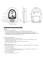
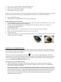
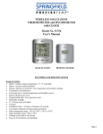
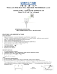
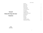
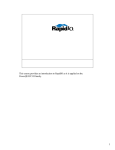
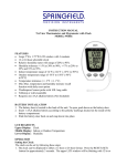
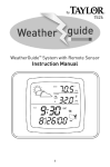
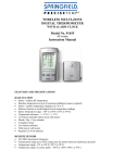
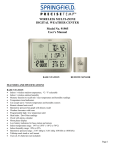
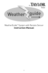
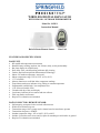
WIRELESS DIGITAL RAIN GAUGE
WITH INDOOR / OUTDOOR THERMOMETER
Model No. 91505-1
Instruction Manual
Rain Collector/Remote Sensor
Base Unit
FEATURES AND SPECIFICATIONS
BASE UNIT:
•
•
•
•
•
•
•
•
•
•
•
•
•
•
•
•
RF rainfall and temperature measurement
Rainfall history tracking: last hour, last 24 hours, daily, weekly and monthly
Bar chart display for rainfall history
Daily Min. / Max. rainfall tracking with auto daily clearing
Features Decline Principal Rain Measurement Technology*
Indoor / RF outdoor temperature, auto scroll
Indoor temperature range: 32°F to 122°F (0°C to 50°C)
°C/°F selectable
Memory function to recall Min./Max. temperature readings
Temperature trend arrow indicates rising, falling or constant temperature
Programmable, audible high / low temperature alert
12 or 24 hour selectable clock
Calendar with day of the week display
Low battery indicator for base station and rain collector
Table top stand or wall mount
Requires 2 AA batteries (not included)
RAIN COLLECTOR / REMOTE SENSOR:
•
•
•
•
•
•
•
Self-emptying, waterproof with oversized collection area
Wide base to minimize tip-over
Transmission range: 100 ft. (range may be shorter based on interference present)
Transmission frequency: 433MHz
Outdoor temperature range: -4°F to 140°F (-20°C to 60°C)
Includes (2) stainless steel screws and (2) spikes for mounting to solid surface or ground
Requires 2 AA batteries (not included)
Clock
Mode
(-)
( +)
In-Out Temp
History
Max/Min
Clear
Alert Reset
Re-sync
BATTERY INSTALLATION AND ACTIVATION
Warning:
• Do not mix old and new batteries.
• Do not mix alkaline, standard (carbon zinc), or rechargeable (nickel cadmium) batteries.
• For maximum performance in normal conditions we recommend using good quality alkaline batteries.
When temperatures are below 32°F, alkaline batteries can lose power resulting in a loss of remote
transmission. If you reside in an area that experiences frequent temperatures below freezing, we recommend
using lithium batteries to minimize the loss of transmission.
Battery installation of Base Unit
• Remove the vinyl label from the LCD of the base unit.
• Open the battery door at the back of the base unit and insert (2) AA batteries according to the polarity
markings. Replace the battery door.
• Insert the end of a paper clip into the hole in RESET and push the button.
• Set the clock and calendar as follows.
Setting the Calendar, Clock, °C / °F:
• When either the clock or calendar is being displayed, press and hold the MODE button for 3-4 seconds until
the year display is flashing
• Press + or – to set the year
• Press MODE to display the date
• Press + or – to set the month and day (Month and day are not set independently. Push and hold + or – to
fast scroll through to the month and day you want to set).
• Press MODE to display time
• Press + or – to set the time
• Press MODE and the display will show 12 hr
•
•
•
•
Press + or – to set your clock to 12 hr or 24 hr time format
Press MODE and the temperature field will be flashing
Press + or – to select °F or °C format
Press MODE to lock in the settings
Note: If you set the time and date after initial activation, the accuracy of the rainfall history data may be affected.
Reset the unit to clear the history by pressing the RESET button then set your desired time and date.
•
•
Press the RE-SYNC button.
Position the Rain Collector/Remote Sensor close to the base unit.
Battery installation of Rain collector
• See photos below. Press the hook and open the rain collector unit outer case and remove the inner cover to
access the RESET/RE-SYNC buttons. (Diagram 2)
• Using a coin, unscrew the battery door at the bottom of the rain collector and insert (2) AA batteries
according to the polarity markings.
• Press the RESET button.
• Replace the battery door. Make sure the door is closed securely to prevent water leakage.
• Remove the tape from the pendulum inside to allow it to move freely.
• Close the outer case.
• When the OUT temperature is shown on the display of the base unit, synchronization between the base unit
and the remote sensor is complete.
POWER UP SYNCHRONIZATION
The base unit will search for the RF signal from the rain collector for 6 minutes after reset or after batteries are
inserted. When the temperature display on the main unit shows the OUT temperature, synchronization between
the base unit and remote unit is complete.
The top, left of the base unit display will show the
icon to indicate signal transmission. If the OUT
temperature does not show on the display within 6 minutes after reset, press the RE-SYNC button and the main
unit will search for the RF signal for another 6 minutes. If the base unit still fails to show the out temperature,
refer to the LOSING SYNCHRONIZATION section.
Locating the Base Unit and Remote Sensor
• Choose a suitable place for the base unit and remote outdoor sensor, within the transmission distance.
• Place the base unit near a window, but away from direct sunlight or sources of heat or air conditioning to
ensure accurate temperature readings.
• The location you choose is critical for maximizing the transmission range. The remote sensor is designed to
transmit unimpeded 80 to 100 ft. Transmitting through walls, metal doors and metal framed windows may
reduce the transmission range. To optimize the transmission distance, the remote unit should be positioned
in a location that minimizes these obstructions. Other interference from electrical sources such as home
security systems, wireless doorbells and wireless home entertainment equipment may interrupt the
transmission signal temporarily.
Notes:
• The outdoor rain collector must be placed on a level, horizontal surface for accurate rainfall measurement.
• Use the enclosed screws to mount the rain collector on a solid surface or use the metal spikes to secure the
unit in a grassy area.
• Warning: Ice will affect the accuracy of rainfall readings and will damage the internal mechanism of the
rain collector. In temperatures below freezing the collector can remain outdoors for temperature data
transmission, but the unit must be placed in a protected area to prevent ice damage.
INDOOR AND OUTDOOR TEMPERATURE
•
•
•
•
The indoor temperature is shown after activation until the first outdoor temperature signal is received. The
display will then change to the outdoor temperature reading.
Press the IN-OUT TEMP button to toggle between indoor and outdoor temperature.
To activate Auto Scroll mode, press and hold the IN-OUT TEMP button for 3-4 seconds. Double curved
arrows will show at the top of the LCD display and the unit will automatically toggle between indoor and
outdoor temperature. Press and hold the IN-OUT TEMP button for 3-4 seconds to de-activate Auto-Scroll
mode.
The temperature trend arrow which is located directly above the temperature reading will indicate the trend
of indoor and outdoor temperatures during the last three minutes.
TEMPERATURE ALERT
When either the indoor or outdoor temperature exceeds the upper or lower pre-set limits, the alarm will sound
for five seconds. It will be accompanied by a flashing alert icon and flashing arrow to show that the temperature
has reached the upper or lower limit. The audible alert will sound for five seconds every minute.
Setting the Temperature Alert:
• When setting the alert temperatures, the display will change in increments of 1.8°F or 1.0°C.
• Press and hold the ALERT button until the alert icon, up arrow and IN icon are shown on the display and
the alert temperature is flashing
• Press + or - to set the desired indoor alert temperature upper limit
• Press ALERT and the down arrow will be displayed. Press + or - to set the desired indoor alert temperature
lower limit
• Press ALERT and the up arrow and OUT icon will be displayed. Press + or - to set the desired outdoor alert
temperature upper limit
• Press ALERT and the down arrow will be displayed. Press + or - to set the desired outdoor alert temperature
lower limit
• Press ALERT to confirm the settings and exit the alert temperature setting mode.
Activating the Temperature Alert:
• After you have entered all your temperature alert limits press ALERT and the system will be activated.
The alert icon will show on the display.
De-activating the Temperature Alert:
• Press the ALERT button when either the indoor or outdoor temperature has exceeded the limit. The audible
alert will stop and the alert icon will stop flashing. The arrow icon will continue to flash to indicate the out
of range condition.
• The alert will sound again if the indoor or outdoor temperature falls back within the upper or lower limit and
then exceeds the upper or lower limit again.
• To turn off the alert permanently, press ALERT until the alert icon is no longer displayed.
VIEWING CLOCK, CALENDAR, RAINFALL RATE AND TOTAL RAINFALL
•
•
Press the MODE button to toggle the main display between time, date, rainfall rate and total rainfall.
The rainfall reading is accumulative data since the last press of either the RESET or CLEAR button. To
clear the rainfall reading, press the CLEAR button when the rainfall reading is shown on the display.
RAIN FALL HISTORY
This unit has a large capacity memory that can store and display:
• Last hour rain fall
• Last 24 hours total rain fall
• Daily rain fall ( Up to last six days as well as current day)
• Weekly rain fall ( Up to last six weeks as well as current week )
• Monthly rain fall ( Up to last six months as well as current month )
The Daily Rainfall history bar chart is set as the default display after activation.
To view the rainfall history for other time periods:
• Press HISTORY once to display the weekly rainfall
• Press again to display monthly
• Press again to display last hour (will display for 5 seconds only)
• Press again to display last 24 hours (will display for 5 seconds only)
• Press again to return to daily
The rainfall history bar chart displays in increments from 0.1” to 6.0”. Most of the time the actual rainfall
reading will fall between increments. The bar chart will show the last increment that was actually reached.
For example: If the actual rainfall is 0.8”, the bar chart will show 0.5”. The chart will not show 1.0” until the
actual rainfall total reaches 1.0”.
More detailed daily, weekly and monthly history data are available. Press and hold the HISTORY button when
your desire corresponding history data are shown. The “0” (Current) bar will show up and the precise data will
be shown on the time display. Press + or – and you can scroll through the daily, weekly or monthly prior data.
Note: On the bar chart display, the “0” represents the current period. -1, -2, etc. indicate the prior periods.
MAXIMUM AND MINIMUM RECORDS
Temperature Maximum and Minimum
The highest and lowest record of indoor temperature, outdoor temperature and rainfall are stored automatically
after you activate the base unit. You can recall the records at any time by pressing the MAX/MIN button. With
each press of the button, in sequence the display will show; indoor maximum reached, indoor minimum reached,
outdoor maximum, outdoor minimum, rainfall maximum and rainfall minimum. The corresponding MAX or
MIN icon will be displayed each time. To clear any maximum or minimum record, press the CLEAR button
when the appropriate record is shown on the display.
Rainfall Maximum and Minimum
The rainfall maximum and minimum record is a daily record which counts from 12:00am to 11:59pm every day.
Aside from the automatic daily clear, the rainfall maximum or minimum record can be cleared by pressing the
CLEAR button when the appropriate record is shown on the display.
LOSING SYNCHRONIZATION
If the main unit displayed a proper OUT temperature and rainfall rate, but now displays blanks “--.-C” or
“--.—in”, the unit may have lost synchronization. If this occurs, press the RE-SYNC button of the main unit.
The base unit will search for the RF signal for 6 minutes and will re-initialize synchronization with the remote
unit.
FCC STATEMENT OF COMPLIANCE
This device complies with Part 15 of the FCC rules. Operation is subject to the following two conditions: (1)
This device may not cause harmful interference, and (2) This device must accept any interference received,
including interference that may cause undesired operation.
Warning: Changes or modifications to this unit not expressly approved by the party responsible for compliance
could void the user’s authority to operate the equipment.
NOTE: This equipment has been tested and found to comply with the limits for a Class B digital device,
pursuant to Part 15 of the FCC Rules. These limits are designed to provide reasonable protection against harmful
interference in a residential installation. This equipment generates, uses and can radiate radio frequency energy
and, if not installed and used in accordance with the instructions, may cause harmful interference to radio
communications.
However, there is no guarantee that interference will not occur in a particular installation. If this equipment does
cause harmful interference to radio or television reception, which can be determined by turning the equipment
off and on, the user is encouraged to try to correct the interference by one or more of the following measures:
• Reorient or relocate the receiving antenna.
• Increase the separation between the equipment and the receiver.
• Connect the equipment into an outlet on a circuit different from that to which the receiver is connected.
• Consult the dealer or an experienced radio/TV technician for help.
LIMITED WARRANTY
Taylor® warrants this product to be free from defects in material or workmanship for one (1) year for
the original purchaser from date of retail purchase. It does not cover damages or wear resulting from
accident, misuse, abuse, commercial use, or unauthorized adjustment and/or repair. If service is
required, do not return to retailer. Should this product require service (or replacement at our option);
please contact Taylor Customer Service at 1-866-843-3905.
There are no expressed warranties except as listed above. This warranty gives you specific legal
rights, and you may have other rights which vary from state to state. Keep this book and your sales
slip together for future reference. You must provide proof of purchase for warranty purposes. For
additional product information, or warranty information in Canada or elsewhere outside the USA,
please contact us through www.taylorusa.com.
© 2010 Springfield® is a registered trademark of Taylor Precision Products and its affiliated
companies. All rights reserved. Made to our exact specifications in China.
www.taylorusa.com