1
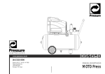
Concept
Instruction and
maintenance manual
cod. 197634000 - Ed.5 - 03/2004
ENGLISH
INDEX
FOREWORD ........................................................................ 3
1.GENERAL INFORMATION ..................................................... 4
2. INSTALLATION ................................................................. 6
3. START-UP ....................................................................... 6
4. MAINTENANCE ................................................................. 8
5.TROUBLESHOOTING ........................................................ 10
6.WIRING DIAGRAMS ......................................................... 11
2
FOREWORD
Use of the Instruction manual
This manual is integral part of this compressor and should be kept for its whole working
life.
Keep this manual in a safe place so not to damage it.
If the compressor is sold to a third party, also give the Instruction Manual to the new Owner.
This manual should be carefully read before starting the compressor up and in case of any
doubt on its operation.
This manual contains important safety information on operation procedures, which should
be complied with, otherwise injuries to people or damages to the machine might occur.
Important use and maintenance instructions are also mentioned in this manual.
Should this manual be lost, please ask for a new copy
Spare parts list is not considered as integral part of this manual, since it is available at
authorized dealers’ offices only.
Symbols
The following symbols are used for especially important information:
Caution
Highlights precautions to be taken to ensure safety of the operator, people in the
compressor working area and the compressor.
Notes
Highlights recommended instructions or precautions to be taken to have an easier
maintenance procedure or to explain most important instructions.
Specialized personnel
Every intervention highlighted by this symbol is exclusively the job of a specialized
technician.
Technical Assistance
Use only genuine spare parts for servicing the compressor.
Non-genuine spare parts might cause injuries to people. For efficient Technical Assistance,
please always state model, type and part number of Your compressor. Those data are
specified both on compressor plate and label on manual cover page.
Product identification
Manufacturer’s data
TYPE = name
CODE = compressor code
SERIAL NO. = serial number
1
Air delivered (l/min) and (cfm)
4
Technical data:
voltage (V/ph/Hz)
absorption (A)
power (HP and kW)
rotations per minute (Rpm).
6
2
3
5
CE mark
year
of manufacture
max. pressure
(bar and PSI)
noise level
dB(A)
7
other
approvals
3
1.GENERAL INFORMATION
This compressor was designed and manufactured to be used only to deliver compressed
air for handicraft and/or industrial applications in full compliance with the safety instructions
provided in the following paragraphs.
Compressor can be equipped with several accessories for blowing, washing and painting
as well as air tools. See the relevant manuals for correct use of accessories and tools.
Carefully read the User’s Manual before servicing the compressor.
Before performing maintenance work, switch off the compressor and cut off power supply
by switching off the wall-mounted switch (if any).
What SHOULD BE DONE:
• Understand how to stop the compressor at once and become familiar with the use of all
controls.• Before any operation the compressor tank should be emptied. Unplug the
compressor so to avoid any
accidental compressor start.
• After any maintenance operation make sure all the disassembled parts are properly
assembled.
• To have a safe operation, make all checks mentioned in chapter “Start-up” before starting
the compressor.
• Keep children and animals away from the working area, so as to avoid any injury
caused by devices
connected to the compressor.
• Carefully read the instructions of any tool you have installed, especially if a spray gun is
used, make sure the shop is well ventilated before you start painting.
• Always start and stop three-phase compressor through the wall switch.
• Should the compressor be working around the clock, the use of soundproof headset is
recommended.
What SHOULD NEVER BE DONE:
• Do not paint indoor or close to naked flames.
• Never touch cylinder head, cooling fins and delivery tube since they become very hot
while working. They are still very hot for some time after stopping the compressor.•
Never place inflammable nylon or cloth objects near or/and on the compressor.
• Never move the compressor when the tank is under pressure.
• Never use the compressor if the power cable is faulty or the connection is not safe.
• Never aim the air jet either at people or animals.•
Never allow anyone to operate
the compressor without giving him/her proper instructions
• Never hit flywheel and fans with metal or blunt objects. Compressor might break or be
seriously damaged.
• Never operate the compressor without an air filter.
• Never tamper with the safety valve or the tank.
• Never use the compressor in potentially explosive premises.
• Never connect the air outlet cock to a tube with a max. capacity which is lower than the
compressor capacity.
Never run the compressor when temperature is under 0°C (operating temperature
range: +5°C / +45°C). Apart from model Concept 870/7,5 V230/50 (operating temperature
range: +5°C / +40°C)
4
1.GENERAL INFORMATION
Standard accessories
1
Your compressor is delivered with the following accessories
(fig.1):
• User’s manual
• Vibration-dampers + key to open panels
• Elbow + line cock + Teflon tape
• Connection hose.
Unpacking and Handling (fig.2)
• The compressor is usually shipped to the customer
with a carton cover. Wear protective gloves and cut outer
straps. Remove then package by lifting it from the top.
2
• Before removing the compressor, make sure it is intact
(outside), open access doors (if any) and visually check
components for damage. Check that all accessories are
included.
• Lift machine with a transpallet or fork lift truck, fit the
vibration-damping pads in their housings and transport the
machine with the utmost care to the place of installation.
Connect the elbow as shown, and then connect the
connection hose and the line cock supplied.
• You are advised to keep the packing material in the event
you need to re-locate the compressor. Keep package at
least for the duration of the warranty period, so the
compressor can be safely shipped to a service centre, if needed.
When no longer needed, deliver packing material to the special collection centres for
disposal.
Compressor description
Compressor main components are (fig.3):
1. Bare pump
2. Air radiator
3. Oil control
(apart from SE models)
4. Check valve
5. Electric motor
6. Pressure switch
(positioned outside
on SE models)
7. Control panel
(apart from SE models)
8.Electric
equipment
(apart from SE models)
3
6
1
2
3
7
4
5
5
8
2. INSTALLATION
Placement
Upon installation, make sure that the chosen place is in compliance with all prevailing
national safety standards and meets the following requirements:
• low percentage of dust suspended in air,
• shop must be suitably sized and well ventilated so that room temperature never exceeds
40°C when the compressor is working. If this is not the case, install one or more exhaust
fans to extract hot air. Ideally, the fans should be installed close to the ceiling.
Power connection
The compressor undergoes functional testing at the factory and is delivered ready for use.
• Power connection is a critical phase of installation. Before making any operation, make
sure that mains voltage is the same as the voltage rating specified in the CE plate and that
switch is set to (0) (fig.4).
• Have a wall-mounted switch provided with plug fuses
4
(rating must be at least equal to the values indicated in the
I
relevant table) installed upstream of the control panel by a
0
skilled technician. Switch should be installed within the
operator’s reach. See wiring diagrams on chapter 6.
In the event the machine needs to be modified for
compliance with the rules in force in the User’s country or
for any other requirements, have the job performed by skilled
personnel only.
Power
Absorption
Absorption
HP
V 230
A
V 400
A
4
5,5
12,5
16,6
7,2
9,6
7,5
22
12,7
3. START-UP
Type of operation
START-STOP working : compressor starting is controlled by a pressure switch (5 seconds
are needed for models with automatic starter).
The compressor will stop when max. pressure is reached and it will automatically restart
only when pressure is at the minimum allowed value.
Working pressure adjustment
• At User’s discretion, a pressure reducer can be installed downstream of the compressor.
Have the distribution line configured by a qualified technician.
• Always look up the ideal operating pressure of the tool you wish to use in the relevant
manual.
• After use, set pressure to 0 in order to prevent early wear of pressure reducer.
6
3. START-UP
Controls and check devices
The control panel (apart from SE models) includes the
following controls and check devices (fig. 5):
1. On/Off Switch (I/0)
2. Oil level light
3. Emergency stop button (to be used only in an emergency)
4. Working hour counter
5. Air pressure gauge at delivery end
3
4
I
0
5
1
2
5
Once machine has been placed and connected to mains, it
is ready for operation.
It is recommended this operation - operational test - be
performed by a specialized technician. Before continuing,
make sure that
· mains voltage is the same as voltage mentioned in the
CE plate
MAX
MAX
· all connections have suitable cross-section cable and
that cables are neither damaged nor have bare wires;
MIN
MIN
· wall-mounted switch is equipped with suitable fuses
MAX
· oil level is above the minimum (fig. 6)
6
· machine has been connected to tank.
MIN
After checking the above, proceed as follows:
· Power the wall switch on
7
· Start the compressor powering the switch.
· Check that the direction of rotation is the same as
indicated by the arrow (fig.7).
If the compressor is running in the wrong direction of rotation,
power the machine immediately off. Power the main switch
off and reverse two phases at terminals L1-L2-L3 of the
switch. Restart the machine after powering the voltage
on.Allow the motor to run for at least 5 minutes with the air
cock open. Close the air cock and check that compressor
is loading tank and that it duly stops once pressure gauge
5 detects that max. pressure has been reached.
Now you may appreciate the easiness of use of your compressor. The pressure switch,
which stops the motor when the max. pressure allowed is achieved, makes the compressor
start again when pressure goes below the minimum threshold (about 2 bar less than the
max. pressure).
To stop the compressor, always use switch 1. That way, compressed air is drained from
inside the head and re-starting is facilitated. Press the emergency stop button 3 in emergency
cases ONLY.
First start-up
Safety devices
• Operating pressure switch (see fig.3/4): determines STOP and START pressures.
• Oil level control (fig. 6) - Apart from SE models
1) Oil level is checked every 5 seconds during compressor standard operating mode. If the
feeler detects a low oil level for 12 times in a row, the compressor is stopped and the
warning light (fig. 5 – ref. 2) turns on (steady light).
What to do: power off and check the oil level, top up if necessary. Allow some minutes and
7
4. MAINTENANCE
then restart the compressor. Should the machine stop once again, call an authorized
service center.
2) If the light (fig. 5 – ref. 2) flashes after starting up the compressor or during compressor
standard operation, the following might have happened:
feeler short-circuited or contact open. Call an authorized service center in any case, as the
feeler needs to be replaced.
Should the above happen, the compressor can work for 3 hours more. Then it should be
powered off and on again to continue working until the feeler is replaced.
ALWAYS CHECK OIL LEVEL BEFORE RESTARTING THE COMPRESSOR.
Before carrying out any maintenance operation:
Switch off the machine and the wall-mounted switch.
Bleed air from inside compressor and/or tank.
Close the air cock between compressor and tank
Cabinet panels disassembly
Front and upper panels have to be removed to access the
compressor (fig. 3).
Front panel: use the key supplied with the machine to open
the locks and remove panel by first pulling it upwards and
then outwards
Upper panel: unscrew the 4 screws with a 5-mm socket
wrench and lift the panel.
Never operate the compressor with the protection panels
removed.
8
oil
After the first 100 operating hours
• Check that all screws are tightened, with special
attention to head screws.
• Check that all tubing connectors are tightened.
• Check that the terminals of all wires brought to the control
panel are tightened.
• Check for any dust inside the cabinet to determine
whether the conditions in the shop meet recommended
requirements. If so, the compressor should be cleaned.
• Change oil in the tank. Use one of the recommended
safety oils (see following par.).
EVERY 50 HOURS: oil level check and top-up
Remove front panel and check oil level. If the level is below
MAX., top up through filler plug (see fig.8 - following page).
EVERY 300 HOURS: suction filter cleaning
Remove the suction filter and clean or change the filter
element as required.
Clean the filter element as follows (fig. 9):
wash in a solution containing normal detergent, rinse and
dry completely before refitting.
8
9
4. MAINTENANCE
Do not operate the compressor without the suction filter fitted, as foreign bodies or dust
could seriously damage the inside components.
NOTE: REPLACE FILTERING CARTRIDGE EVERY TWO OIL CHANGES.
EVERY 300 HOURS: oil change
• Remove front panel and undo the filler plug. Drain the oil through the drain hose and
collect in a container. Close the drain plug and fill new oil (see fig. 8).
Top up and change oil when the compressor is hot.
Never mix different oils. Poor-quality oils may provide inadequate lubricating performance. Select oil type from the relevant table.
Recommended oils
SHELL Rimula D Extra 15W-40
AGIP Dicrea 100
BP Energol CS100
ESSO Exxc Olub H150
MOBIL Rarus 427
FUCHX Renolin 104L VG100
API CM-8X
CASTROL Aircol PD100
IP Calatia Oil ISO 100
TOTAL Dacnis P100
EVERY 500 HOURS: drive belt tension check
• Remove upper and rear panels. To check belt tension,
apply a 30N/3 kg weight (fig. 10) at belt mid-length. Belt
flexion should be about 10 mm.
Loosen electric motor nuts. Tension up belt at motor end,
taking care to preserve alignment with compressor pulley.
Re-tighten the nuts.
10
3 Kg.
10 mm
Routine maintenance
• Every 6 months
Clean air radiator and all radiator fins to preserve cooling
efficiency and ensure greater machine performance.
• Every 2 years
1) Check and clean suction and delivery valves.
2) Inspect check valve and change seal (A) (fig.11), if
necessary.
In these cases it is recommended to change relevant
gaskets.
11
A
Compressor disposal
Dispose of all materials according to prevailing rules.
Always contact special disposal and recycling centres.
9
5.TROUBLESHOOTING
Problem
Cause
Remedy
Air leaking off pressure
switch valve when the
compressor is stopped.
Check valve leaking.
Bleed air off the tank, remove the check
valve cap and clean valve seat and
sealing element. Replace the sealing
element, if necessary.
Air leaking off pressure
switch valve for a long time
when the compressor is
running.
Loadless start valve broken.
Replace the valve.
The compressor stops and
cannot be restarted.
Oil Control has triggered.
Top up with oil and restart. Should the
compressor stop once again, call a
specialized technician.
Winding burnt.
Call a specialized technician.
The compressor stops once Pressure switch defective or Call a specialized technician.
max. pressure has been
broken.
reached and the safety valve
starts working.
The compressor does not
charge and causes
overheating.
Heat gasket or valve broken.
Stop the compressor with no delay and
call a specialized technician.
The compressor is too noisy
and rattles.
Bearings seizure.
Stop the compressor with no delay and
call a specialized technician.
6.WIRING DIAGRAMS
SE Models
(without electric equipment)
PE
L1 L2 L3
1) Electric motor
2) Pressure switch with
oveload cutout
2A) Thermal relay
P
2
2A
1
3
10
M
6.WIRING DIAGRAMS
Models with direct starting
P
h
TC ......................
FU1-FU2-FU3 ....
KM1 ...................
KM4 ...................
FR ......................
SB1 ...................
SB2 ...................
SB3 ...................
Y V .....................
KL ......................
SL ......................
HL1 ....................
HL2 ....................
PT ......................
Jumper ..............
transformer
Fuses 6.3x32 4A
Line contactor 230V 50-60Hz
Ancillary contactor 230V 50-60Hz
Thermal relay
Emergency stop button
Luminous button + bulb carrier
Reset button FR
solenoid valve
Oil control
Oil level probe
White indicator light
Yellow indicator light
Hour counter
For remote control installation
11
Motor cable cross-section:
4 Hp compressors
V230 ................. 4G2.5 sq mm
V400 ................. 4G1.5 sq mm
5.5 HP compressors
V230 ................. 4x4 sq mm
V400 ................. 4G1.5 sq mm
7.5 HP compressors
V230 ................. 4x6 sq mm
V400 ................. 4G2.5 sq mm
6.WIRING DIAGRAMS
Models with automatic starter
TC ......................
FU1-FU2-FU3 ....
KM1 ...................
KM2 ...................
KM3 ...................
KM4 ...................
KT ......................
FR ......................
SB1 ...................
SB2 ...................
SB3 ...................
Y V .....................
KL ......................
SL ......................
HL1 ....................
HL2 ....................
PT ......................
Jumper ..............
transformer
Fuses 6,3x32 4A
Line contactor 230V 50-60Hz
Delta contactor 230V 50-60Hz
Star contactor230V 50-60Hz
Ancillary contactor 230V 50-60Hz
Timer
Thermal relay
Emergency stop button
Luminous button + bulb carrier
Reset button FR
solenoid valve
Oil control
Oil level probe
White indicator light
Yellow indicator light
Hour counter
For remote control installation
12
Motor cable cross-section:
5.5 HP compressors
V230 ................. 7G2.5 sq mm
V400 ................. 7G1.5 sq mm
7.5 HP compressors
V230 ................. 7G2.5 sq mm
V400 ................. 7G2.5 sq mm