1
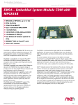
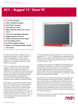
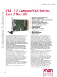
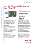
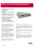
MM1 Data Sheet - 2012-04-02
Embedded Solutions
MM1 - ESMini™ COM with Intel®
Atom™
n
n
n
n
n
n
n
n
n
n
n
The MM1 is an ultra-small Computer-On-Module of the
rugged ESMini™ family. Together with an applicationspecific carrier board it forms a semi-custom
solution for industrial, harsh, mobile and missioncritical environments.
The MM1 is controlled by the Intel® Atom™ processor, a
first generation IA-32 core based on 45nm process
technology. Due to the new power architecture of the
Intel® Atom™ CPU, the MM1 has a total power
consumption of max. 5 to 10 W, while having a clock
frequency of up to 1.6 GHz.
The MM1 accommodates up to 1 GB of directly soldered
main memory and supports other memory like USB Flash
on the carrier board.
The MM1 offers a multitude of I/O: besides modern
serial I/O like one PCI Express® x1 link, LVDS, SDVO,
high-definition audio, SATA and USB, it also provides
legacy I/O (2 CAN, 2 COM, 2 Fast Ethernet, 2 I2C) and
up to 120 FPGA signals.
The MM1 is completed by a board management
1
Intel® Atom™ Z530 or Z510, up to 1.6 GHz
Up to 1 GB DDR2 SDRAM
1 PCI Express®
Up to 2 Fast Ethernet interfaces
8 USB 2.0 (1 client)
2 UARTs
Up to 2 CAN bus interfaces
SDVO, LVDS
Intel® HD Audio
-40°C to +85°C Tcase screened (-25°C to
+85°C Tcase with 1 GB DRAM)
Conduction cooling
controller for temperature and power supervision. It
comes with a Phoenix® Award BIOS configurable for
the final application.
The MM1 is screened for operation in a -40°C to +85°C
temperature range (Tcase, -25°C to +85°C for board
versions with 1 GB DRAM). As all ESMini™ modules it is
embedded in a covered frame. This ensures EMC
protection and allows efficient conductive cooling.
Air cooling is also possible by applying a heat sink
on top of the cover. Where operation temperatures are
moderate, the module may even do without the frame
and cover, with a suitable low-power processor and
airflow. ESMini™ modules are firmly screwed to a
carrier board and come with rugged industry-proven
connectors supporting high frequency and
differential signals. Only soldered components are
used to withstand shock and vibration, and the
design is optimized for conformal coating. The MM1
supports a 95x55mm form factor.
For evaluation and development purposes a microATX
carrier board is available.
®
MM1 Data Sheet - 2012-04-02
Embedded Solutions
Technical Data
CPU
n Intel® Atom™ Z530 or Z510
o Up to 1.6 GHz processor core frequency
o 400 MHz or 533 MHz system bus frequency
n Chipset
o Intel® system controller hub US15W
Memory
n 512 KB L2 cache integrated in Atom processor
n Up to 1 GB DDR2 SDRAM system memory
o Soldered
o 400/533 MHz memory bus frequency locked to the FSB
frequency
Serial ATA (SATA)
n One port via ESMini™ connector
n Transfer rates up to 100 MB/s
n Via PATA-to-SATA converter
Graphics
n Integrated in Intel® System Controller Hub US15W
n Maximum resolution: 1366x768 pixels
n 1 SDVO port
n 1 LVDS port
o 112 MHz maximum pixel clock
o 18 or 24 bits pixel color depths
n Available via ESMini™ connector
USB
n Eight USB 2.0 host ports (or 7 host ports and 1 client
port, adjustable by software)
o Via ESMini™ connector
o Six of these ports also support USB 1.1 (UHCI
implementation)
n EHCI implementation
n Data rates up to 480 Mbit/s
Ethernet
n Up to two 10/100Base-T Ethernet channels
n Two status LEDs per channel
n Available via ESMini™ connector
UART
n Two interfaces
n RS232 or RS422/RS485
n Full or half-duplex
n Data rates up to 115,200 bit/s
n 60-byte transmit/receive buffer
n Handshake lines: RTS, CTS
n Available via ESMini™ connector
2
CAN bus
n Two CAN bus channels
n 2.0 A/B CAN protocol
n Data rates up to 1 Mbit/s
n Available via ESMini™ connector
I²C Bus
n Two interfaces
n Available via ESMini™ connector
PCI Express®
n One x1 link to connect legacy I/O (FPGA)
n One x1 link via ESMini™ connector
n Data rate 250 MB/s in each direction (2.5 Gbit/s per lane)
GPIO
n One line from board controller on ESMini™ connector J1
n Three lines from FPGA on ESMini™ connector J1
n Up to 19 differential pairs of receive and transmit lines
on ESMini™ connector J2
n Up to 116 single I/O lines on ESMini™ connector J2
HD Audio
n Via ESMini™ connector
Board Management Controller
n Input voltage supervision
n Power sequencing
n Board monitoring
n Watchdog
n Accessible via SMBus
Miscellaneous
n Real-time clock (with Goldcap or battery backup on the
carrier board)
n SMBus interface
Electrical Specifications
n Supply voltage: +5V (-3%/+5%)
n Power consumption:
o 1.1 GHz Z510 model: 6.75 W typ., 7.7 W max.
o 1.6 GHz Z530 model: 7.5 W typ., 9.3 W max.
Mechanical Specifications
n Dimensions: 95 mm x 55 mm
n ESMini™ PCB mounted between a frame and a cover
n Weight: 130 g (with cover and frame)
Environmental Specifications
n Temperature range (operation):
o -40..+85°C Tcase (ESMini™ cover/frame) (screened)
(board versions with 512 MB DDR2 SDRAM)
o -25..+85°C Tcase (ESMini™ cover/frame) (screened)
(board versions with 1 GB DDR2 SDRAM)
®
MM1 Data Sheet - 2012-04-02
Embedded Solutions
Technical Data
n
n
n
n
n
n
n
n
Temperature range (storage): -40..+85°C
Relative humidity (operation): max. 95% non-condensing
Relative humidity (storage): max. 95% non-condensing
Altitude: -300 m to + 3,000 m
Shock: 15 g/11 ms (EN 60068-2-27)
Bump: 10 g/16 ms (EN 60068-2-29)
Vibration (sinusoidal): 1 g/10..150 Hz (EN 60068-2-6)
Conformal coating on request
MTBF
n 221,026 h @ 40°C according to IEC/TR 62380 (RDF 2000)
Safety
n PCB manufactured with a flammability rating of 94V-0 by
UL recognized manufacturers
EMC
n EMC behavior depends on the system and housing
surrounding the ESMini™ module. MEN has performed
general, successful EMC tests for ESMini™ using the XC4
evaluation carrier according to EN 55022 (radio
disturbance), IEC 61000-4-2 (ESD), IEC 61000-4-3
(electromagnetic field immunity), IEC 61000-4-4 (burst),
IEC 61000-4-5 (surge) and IEC 61000-4-6 (conducted
disturbances)
BIOS
n Award BIOS
Software Support
n Windows®
o Windows® XP
o Windows® Vista™
o Windows® 7
o Windows® XP Embedded
o Windows® Embedded Standard 7
n Linux (in preparation)
n VxWorks® (on request)
n QNX® (on request)
n For more information on supported operating system
versions and drivers see Software.
3
®
MM1 Data Sheet - 2012-04-02
Embedded Solutions
Diagram
4
®
MM1 Data Sheet - 2012-04-02
Embedded Solutions
Configuration & Options
Standard Configurations
Article No.
CPU Type
Clock
System RAM
Ethernet
CAN
ESMini™
Connectors
Operating
Temperature
15MM01-00
Z510
1.1 GHz
512 MB
1
1
J1
-40..+85°C
Tcase screened
15MM01-01
Z530
1.6 GHz
1 GB
2
2
J1, J2
-25..+85°C
Tcase screened
Options
CPU
n Intel® Atom™ Z530, 1.6 GHz
n Intel® Atom™ Z510, 1.1 GHz
Memory
n System RAM
o 512 MB or 1 GB
I/O
n Second Fast Ethernet port
n Second CAN port
PCI Express®
n Second PCI Express® lane on ESMini™ connector
o Instead of FPGA (GPIO, CAN, UART, Fast Ethernet, I²C)
Operating Temperature
n -40..+85°C Tcase (ESMini™ cover/frame) (screened) (board
versions with 512 MB DDR2 SDRAM)
n -25..+85°C Tcase (ESMini™ cover/frame) (screened) (board
versions with 1 GB DDR2 SDRAM)
Cooling
n With cover and frame
n With cooling plate
n With small heat sinks only on processor and chipset
BIOS
n Accessible via UART using VT100 terminal
Software Support
n VxWorks® (on request)
n QNX® (on request)
Please note that some of these options may only be
available for large volumes. Please ask our sales staff
for more information.
5
®
MM1 Data Sheet - 2012-04-02
Embedded Solutions
Ordering Information
Standard MM1 Models
15MM01-00
Intel® Atom™ Z510, 1.1 GHz, 512MB RAM, 1
Fast Ethernet, 1 CAN, -40..+85°C Tcase
screened
15MM01-01
Intel® Atom™ Z530, 1.6 GHz, 1GB RAM, 2 Fast
Ethernet, 2 CAN, -25..+85°C Tcase screened
Related Hardware
08XC04-00
Evaluation and development board for all
ESMini™ modules, 0..+60°C, incl. 2 GB USB
Flash Disk and SA-Adapters™ for 1 RS232 and
1 CAN bus
08XC06-01
Carrier board for ESMini™: 1x TTY, 1x
RS232, 1x DVI-I, 1x Audio I/O, 4x USB2.0,
2x Fast Ethernet, USB Flash slot, PCI
Express® Mini Card socket, SIM card holder,
microSD™ card socket, 8x GPIOs,
-40°C..+85°C screened
Miscellaneous Accessories
0712-0019
Standard ATX PSU, 350 W, 0..+40°C
08XC04-00
Evaluation and development board for all
ESMini™ modules, 0..+60°C, incl. 2 GB USB
Flash Disk and SA-Adapters™ for 1 RS232 and
1 CAN bus
08XC06-01
Carrier board for ESMini™: 1x TTY, 1x
RS232, 1x DVI-I, 1x Audio I/O, 4x USB2.0,
2x Fast Ethernet, USB Flash slot, PCI
Express® Mini Card socket, SIM card holder,
microSD™ card socket, 8x GPIOs,
-40°C..+85°C screened
Software: Linux
This product is designed to work under Linux. See below
for potentially available separate software packages from
MEN.
13XM01-06
MDIS5™ low-level driver sources (MEN) for
XM1, XM1L, MM1, XM2, F11S, F19P, F21P, G20,
SC21 and DC2 board controller
13Z015-06
MDIS5™ low-level driver sources (MEN) for
16Z029_CAN (MSCAN/Layer2)
13Z016-06
MDIS5™ driver (MEN) for 16Z029_CAN (CANopen
master)
13Z017-06
MDIS5™ low-level driver sources (MEN) for
16Z034_GPIO and 16Z037_GPIO
13Z025-90
Linux native driver (MEN) for 16Z025_UART,
16Z057_UART and 16Z125_UART
13Z077-90
Linux native driver (MEN) for 16Z077_ETH
and 16Z087_ETH
Software: Windows
This product is designed to work under Windows®. See
below for potentially available separate software
packages from MEN.
10F014-78
Windows® XP Embedded BSP (MEN) for F11S,
F14, F15, F17, F18, F19P, F21P, G20, XM1,
XM1L, XM2, MM1, MM2, SC21, SC24, DC1, DC2,
RC1 and BC50M
10Y000-78
Windows® Embedded Standard 7 BSP for F11S,
F19P, F21P, G20, XM1L, XM2, MM1, MM2, SC21,
SC24, BC50M, F206, F210, F215, F216, G215,
P506, P507 and P511
13MM01-77
Windows® Installset (MEN) for MM1 and RC1
[Includes all free drivers developed by MEN
for the supported hardware.]
13T009-70
Windows® HD audio driver (Realtek) for XM1,
XM1L, MM1, MM2
13T011-70
Windows® graphics driver (Intel®) for XM1,
XM1L, MM1 and F11S
13T012-70
Windows® XP/Vista chipset driver (Intel®)
for XM1, XM1L, MM1 and F11S
13T013-70
Windows® USB client driver installation
package (Intel®) for XM1, XM1L and MM1
13T014-70
Windows® Vista™ HD audio driver (Realtek)
for XM1, XM1L and MM1
13T016-70
Windows® Vista™ chipset graphics driver
(Intel®) for XM1, XM1L, MM1 and F11S
13Z015-70
MDIS4™/2004/MDIS5™ Windows® driver (MEN)
for 16Z029_CAN (MSCAN/Layer2)
13Z016-70
MDIS5™ Windows® driver (MEN) for 16Z029_CAN
(CANopen master)
13Z017-70
MDIS4™/2004 / MDIS5™ Windows® driver (MEN)
for 16Z034_GPIO devices
13Z087-70
Windows® native driver (MEN) for 16Z087_ETH
(Ethernet controller)
Software: Firmware/BIOS
MEN's CANopen firmware consists of the Vector Informatik
protocol stack. The corresponding driver software comes
from MEN. It is based on MDIS™ (MEN Driver Interface
System), which makes the hardware ready for use under
Windows®, Linux, VxWorks®, QNX®, OS-9® and other software
environments. You can find more information on the Vector
CANopen tools at www.vector-informatik.de.
Software: Miscellaneous
6
®
MM1 Data Sheet - 2012-04-02
Embedded Solutions
Ordering Information
Intel® software development products such as analyzers,
compilers, threading tools etc. can be downloaded under
www.intel.com/cd/software/products/asmo-na/eng/index.htm.
IA-32 Intel® Architecture Software Developer's Manuals
are available under
www.intel.com/products/processor/manuals/index.htm.
For operating systems not mentioned here contact MEN
sales.
Documentation
Compare Chart ESMini™ Computer-On-Modules Download
You can find general literature on MEN
computer-on-modules, including presentations about
ESMexpress®, ESMini™ and their cooling concept, in our
Download Library.
20APPN004
Application Note: How to make a USB stick
bootable
20MM01-ER
MM1 Errata
20MM01-00
MM1 User Manual
21Z025-90
16Z025_UART and 16Z125_UART under Linux
User Manual
For the most up-to-date ordering information and direct
links to other data sheets and downloads, see the MM1
online data sheet under » www.men.de.
7
®
MM1 Data Sheet - 2012-04-02
Embedded Solutions
Contact Information
Germany
MEN Mikro Elektronik GmbH
Neuwieder Straße 3-7
90411 Nuremberg
Phone +49-911-99 33 5-0
Fax +49-911-99 33 5-901
E-mail [email protected]
www.men.de
France
MEN Mikro Elektronik SA
18, rue René Cassin
ZA de la Châtelaine
74240 Gaillard
Phone +33 (0) 450-955-312
Fax +33 (0) 450-955-211
E-mail [email protected]
www.men-france.fr
USA
MEN Micro, Inc.
24 North Main Street
Ambler, PA 19002
Phone (215) 542-9575
Fax (215) 542-9577
E-mail [email protected]
www.menmicro.com
The date of issue stated in this data sheet refers to the Technical Data only. Changes in ordering information given herein do not affect the date of issue.
All brand or product names are trademarks or registered trademarks of their respective holders.
MEN is not responsible for the results of any actions taken on the basis of information in the publication, nor for any error in or omission from the publication.
MEN expressly disclaims all and any liability and responsibility to any person, whether a reader of the publication or not, in respect of anything, and of the
consequences of anything, done or omitted to be done by any such person in reliance, whether wholly or partially, on the whole or any part of the contents of the publication.
The correct function of MEN products in mission-critical and life-critical applications is limited to the environmental specification given for each product in the technical
user manual.The correct function of MEN products under extended environmental conditions is limited to the individual requirement specification and subsequent
validation documents for each product for the applicable use case and has to be agreed upon in writing by MEN and the customer.Should the customer purchase or use
MEN products for any unintended or unauthorized application, the customer shall indemnify and hold MEN and its officers, employees, subsidiaries, affiliates, and distributors
harmless against all claims, costs, damages, and expenses, and reasonable attorney fees arising out of, directly or indirectly, any claim or personal injury or death associated
with such unintended or unauthorized use, even if such claim alleges that MEN was negligent regarding the design or manufacture of the part.
In no case is MEN liable for the correct function of the technical installation where MEN products are a part of.
Copyright © 2012 MEN Mikro Elektronik GmbH. All rights reserved.
8
®