1
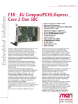
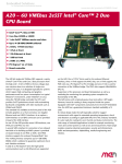
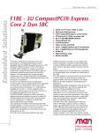
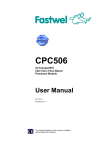
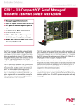
F18 Data Sheet - 2008-02-05
Embedded Solutions
F18 - 3U CompactPCI®/Express
Core 2 Duo SBC
n
n
n
n
n
n
n
n
n
n
n
n
n
n
Equipped with the Intel® high-performance Core 2 Duo
processor T7500 running at 2.2 GHz, the F18 is a
versatile 4HP/3U (single-slot, single-size Eurocard)
single-board computer based on the latest multi-core
processor architecture from Intel® with full 64-bit
support. The board delivers an excellent graphics
performance and is designed especially for embedded
systems which require high computing performance with
low power consumption.
The F18 offers a 32-bit/33-MHz CompactPCI® bus
interface and can also be used without a bus system.
In combination with a specific side card it can also
perform system-slot functionality in a CompactPCI®
Express system.
A total of six PCI Express® lanes for high-speed
communication (such as Gigabit Ethernet, graphics) are
supported on the F18. 2 x1 PCIe links are used for the
two on-board Ethernet interfaces. 4 x1 or 1 x4 PCIe
links are available on a specific side card.
The DDR2 DRAM is soldered to F18 to guarantee optimum
shock and vibration resistance. A robust IDE
CompactFlash® device offers nearly unlimited space for
user applications. In addition to parallel ATA, three
serial ATA lines are available.
The standard I/O available at the front panel of F18
includes graphics on a VGA connector, two PCIe-driven
Gigabit Ethernet interfaces as well as two USB 2.0
ports.
The F18 can be extended by different side cards.
1
Intel® Core™ 2 Duo T7500, 2.2 GHz
Dual core 64-bit processor
Full 64-bit support (4 GB memory addressable)
PCI Express® six x1 links
4 HP system master or stand-alone
32-bit CompactPCI® or cPCI Express®
Up to 4 GB DDR2 DRAM soldered
CompactFlash® slot
3 SATA interfaces
Video via VGA and 2 SDVO
2 Gigabit Ethernet (PCIe)
Up to 8 USB 2.0
High Definition audio
Board controller
Additional functions include two digital video inputs
for flat panel connection via DVI (multimedia), a
variety of different UARTs or another four USB 2.0
ports, SATA for hard disk or RAID connection and HD
audio.The F18 is also prepared for rear I/O where for
example another two USB 2.0 ports can be connected.
Two watchdogs for thermal supervision of the processor
and board temperature as well as for monitoring the
operating system complete the functionality of the F18.
The F18 operates in Windows® and Linux environments as
well as under real-time operating systems that support
Intel®'s multi-core architecture. The Award BIOS was
specially designed for embedded system applications.
Equipped with Intel® components exclusively from the
Intel® Embedded Line, the F18 has a guaranteed minimum
standard availability of 5 years.
The F18 is suited for a wide range of industrial
applications, e.g. for monitoring, vision and control
systems as well as test and measurement. Main target
markets comprise industrial automation, multimedia,
traffic and transportation, aerospace, shipbuilding,
medical engineering and robotics.
The F18 comes with a tailored passive heat sink within
4 HP height. Anyhow, forced air cooling is always
required inside the system. The robust design of the
F18 make the board especially suited for use in rugged
environments with regard to shock and vibration
according to applicable DIN, EN or IEC industry
standards. The F18 is also ready for coating so that
it can be used in humid and dusty environments.
®
F18 Data Sheet - 2008-02-05
Embedded Solutions
Technical Data
CPU
n Intel® Core™ 2 Duo T7500
o Dual-core 64-bit processor
o 2.2GHz processor core frequency
o Up to 667MHz front-side bus frequency
n Chipset
o Northbridge: Intel® 965GME Express
o Southbridge: Intel® ICH8M-E (Enhanced)
n
Memory
n 4MB L2 cache integrated in Core 2 Duo
n Up to 4GB SDRAM system memory
o Soldered
o DDR2
o 667MHz memory bus frequency
o Dual-channel, 2x64 bits
n 8Mbits boot Flash
n Serial EEPROM 2kbits for factory settings
n CompactFlash® card interface
o Via on-board IDE
o Type I
o True IDE
o DMA support
Front Connections
n VGA
n Two USB 2.0 (Series A)
n Two Ethernet (RJ45)
Mass Storage
n Parallel IDE (PATA)
o One IDE port for local CompactFlash®
n Serial IDE (SATA)
o Two channels via side-card connector, up to two
channels via rear I/O (optional)
o Transfer rates up to 150MB/s
o RAID level 0/1 support
Graphics
n Integrated in 965GME Express chipset
o Up to 500MHz 256-bit graphics core
o Maximum resolution: 2048 x 1536 pixels @ 60Hz, 32bpp
reduced blanking timing (driver limited)
n VGA connector at front panel
n Two SDVO ports available via side-card connector
o Two additional DVI connectors at front panel optional
via side card
o Simultaneous connection of two monitors
I/O
n USB
o Two USB 2.0 ports via Series A connectors at front
panel
o Four USB 2.0 ports via side-card connector
o Two USB 2.0 ports via rear I/O on request
o UHCI implementation
o Data rates up to 480Mbits/s
2
n
Ethernet
o Two 10/100/1000Base-T Ethernet channels
o RJ45 connectors at front panel
o Ethernet controllers are connected by two x1 PCIe links
o On-board LEDs to signal activity status and connection
speed
High Definition (HD) audio
o Accessible via side-card connector
Miscellaneous
n Board controller
n Real-time clock, buffered by a GoldCap or alternatively a
battery (5 years life cycle)
n Watchdog timer
n Temperature measurement
n One user LED
n Reset button
PCI Express®
n Two x1 links to connect local 1000Base-T Ethernet
controllers
o Data rate 250MB/s in each direction (2.5 Gbits/s per
lane)
n One x4 or four x1 links for extension through side-card
connector
o Data rate up to 1GB/s in each direction (2.5 Gbits/s
per lane)
CompactPCI® Bus
n Compliance with CompactPCI® Core Specification PICMG 2.0
R3.0
n CompactPCI® Express support (EXP.0 R1.0)
n System slot
n 32-bit/33-MHz CompactPCI® bus
n V(I/O): +3.3V (+5V tolerant)
Busless Operation
n Board can be supplied with +5V only, all other voltages
are generated on the board
n Backplane connectors used only for power supply
Electrical Specifications
n Supply voltage/power consumption:
o +5V (-3%/+5%), tbd, if the F18 is operated with 5V
only, the 3.3V voltage can be used to supply other
CompactPCI® boards in the system, maximum load: 10W
o +3.3V (-3%/+5%), tbd
o +12V (-10%/+10%), tbd
n MTBF: tbd @ 40°C according to IEC/TR 62380 (RDF2000)
®
F18 Data Sheet - 2008-02-05
Embedded Solutions
Technical Data
Mechanical Specifications
n Dimensions: conforming to CompactPCI® specification for
3U boards
n Front panel: 4HP with ejector
n Weight: 420g
Environmental Specifications
n Temperature range (operation):
o 0..+45°C
o Airflow: min. 15m³/h
n Temperature range (storage): -40..+85°C
n Relative humidity (operation): max. 95% non-condensing
n Relative humidity (storage): max. 95% non-condensing
n Altitude: -300m to + 2,000m
n Shock: 15g/11ms
n Bump: 10g/16ms
n Vibration (sinusoidal): 1g/10..150Hz
n Conformal coating on request
Safety
n PCB manufactured with a flammability rating of 94V-0 by
UL recognized manufacturers
EMC
n Tested according to EN 55022 (radio disturbance),
IEC1000-4-2 (ESD) and IEC1000-4-4 (burst) with regard to
CE conformity
BIOS
n Award BIOS
Software Support
n Note that 64-bit hardware technology requires 64-bit
operating system support
n Windows® (including Vista)
n Linux
n VxWorks® (on request)
n QNX® (on request)
n Intel® Virtualization Technology, allows a platform to
run multiple operating systems and applications in
independent partitions; one computer system can function
as multiple "virtual" systems
n For more information on supported operating system
versions and drivers see Software.
3
®
F18 Data Sheet - 2008-02-05
Embedded Solutions
Diagram
4
®
F18 Data Sheet - 2008-02-05
Embedded Solutions
Configuration & Options
Standard Configurations
Article No.
CPU Type
Clock
System RAM
CFlash
Side Card Slot
Operation
Temperature
02F018-00
T7500
2.2 GHz
4 GB
0 MB
right
0..+45°C
Options
CPU
n Core 2 Duo T7500, 2.2GHz (35W)
n Core 2 Duo L7500 1.6 GHz (17W)
n Core 2 Duo U7500 1.06GHz (10W)
Memory
n System RAM
o 256 MB, 512 MB, 1 GB, 2 GB or 4 GB
n CompactFlash®
o 0 MB up to maximum available
Graphics
n One or two DVI-D connectors at front via side card
o Simultaneous connection of two monitors
I/O
n Ethernet
o 9-pin D-Sub connector with one or two 10/100Base-T
ports instead of two RJ45 connectors
Rear I/O
n Two SATA channels (third SATA channel via side-card
connector)
n Two USB 2.0 ports
Mechanical
n Side card can be added at left or right side of CPU
Operation Temperature
n Maximum: +60°C (depending on board configuration (CPU,
heat sink, hard disk, ...))
n Minimum: -40°C (all processors)
Please note that some of these options may only be
available for large volumes. Please ask our sales staff
for more information.
5
®
F18 Data Sheet - 2008-02-05
Embedded Solutions
Ordering Information
Standard Hardware
02F018-00
Related Hardware
02F600-00
2 COM extensions and SATA hard disk slot,
for F14 and compatible SBCs, -40..+85°C
screened
02F601-00
1 DVI-D and 1 audio at front, SATA hard
disk slot, for F14 and compatible SBCs,
4HP, 0..+60°C
02F601-02
2 DVI-D, 1 audio, 1 COM (via SA-Adapter™)
at front, SATA hard disk slot, for F14 and
compatible SBCs, 8HP, 0..+60°C
02F602-00
0701-0041
19" 4U/84HP CompactPCI® Express rack-mount
enclosure, 8-slot hybrid backplane, space
for hard-disk drives, CD-ROM drive, 300W
ATX PSU, 1U fan tray with 2 fans included
0701-0046
CompactPCI® 19" 4U/24HP desktop system for
3U cards, 3-slot 3U CompactPCI® backplane,
system slot right, 1U fan tray with 1 fan,
8 HP space for 1 pluggable PSU
Intel® Core™ 2 Duo T7500, 2.2 GHz, 4 GB
DDR2 DRAM, 2 Gigabit Ethernet, 0..+45°C
3U CompactPCI® to CompactPCI® Express side
card with 1 USB, 1 COM, 1 DVI, SATA hard
disk slot, for F14 and compatible SBCs,
0..+60°C
02F603-00
3U CompactPCI® side card with 2 USB and 1
COM extension, SATA hard disk and
CompactFlash® slot, for F14 and compatible
SBCs, mounted to the right of the SBC,
0..+60°C
02F604-00
3U CompactPCI® side card with 1 IEEE 1394
FireWire, 1 DVI, 1 HD audio and 1 COM
extension, SATA hard disk slot, for F14 and
compatible SBCs, mounted to the right of
the SBC, 0..+60°C
Memory
0751-0023
CompactFlash® card, 2 GB, Type I,
-40..+85°C, fixed bit set
0751-0025
CompactFlash® card, 512 MB, Type I,
-40..+85°C, removable
0751-0026
CompactFlash® card, 256 MB, Type I,
-40..+85°C, removable
0751-0027
CompactFlash® card, 1 GB, Type I,
-40..+85°C, fixed bit set
0751-0031
CompactFlash® card, 4 GB, Type I,
-40..+85°C, fixed bit set
Miscellaneous
05F601-00
Kit (cable only) for connection of 1
SA-Adapter™ to F601-02, SA-Adapters™ to be
ordered separately
0710-0025
SATA hard disk 2.5", 80 GB, 5400 rpm,
24h/7d, -30..+85°C; N.B.: between -30°C to
-20°C power-on time is 12 s typ.
0713-0003
CompactPCI® 3U 1-slot backplane for
stand-alone operation of F14, F15, F17,
F18: 32-bit/33-MHz with rear I/O, 3.3V
supply, ATX-power, power, JTAG, IPMB and
utility connection, 6x screw connection M3
Software: OS independent
13Y001-06
MDIS4™/2004 low-level driver sources (MEN)
for LM63 on SMBus for F14, F15, F17 and
D601
13Y002-06
MDIS4™/2004 low-level driver sources (MEN)
for F14, F15, F17, F18 and D601 board
monitoring
13Y004-06
MDIS4™/2004 low-level driver sources (MEN)
for generic SMBus driver for F14, F15, F17,
D601, F600 and F601
13Y007-06
MDIS4™/2004 low-level driver sources (MEN)
for F14, F15, F17 and D601 board controller
Software: Windows
13F014-77
Windows® driver installation package (MEN)
for F14, F15, F17 and D601
13T001-70
Windows® network driver (Intel®) for F14,
F15, F17, D6, D601 and P601
13T005-70
Windows® USB2UART driver (FTDI) for F14,
F15 and F17
13T006-70
Windows® HD Audio driver (Realtek) for F14,
F15 and F17
13Y001-70
MDIS4™/2004 Windows® driver (MEN) for LM63
on SMBus for F14, F15, F17 and D601
Systems & Card Cages
0701-0021
6
CompactPCI® 19" 4U/84HP rack-mount
enclosure for 3U cards (vertical), 8-slot
3U CompactPCI® backplane, system slot
right, prepared for rear I/O, space for
hard-disk drive, floppy drive, CD-ROM
drive, 300W ATX power supply wide range
100..240VAC on front, 1U fan tray with 2
fans included
®
F18 Data Sheet - 2008-02-05
Embedded Solutions
Ordering Information
13Y002-70
MDIS4™/2004 Windows® driver (MEN) for F14,
F15, F17, F18 and D601 board monitoring
13Y004-70
MDIS4™/2004 Windows® driver (MEN) for SMBus
devices for F14, F15, F17, D601, F600 and
F601
13Y007-70
MDIS4™/2004 Windows® driver (MEN) for F14,
F15, F17 and D601 board controller
Software: VxWorks
13Y003-60
VxWorks® driver (MEN) for USB-to-UART
bridges on F600, F601, F602, F603 and F604
Documentation
20APPN004
Application Note: How to make a USB stick
bootable
20F018-00
F18 User Manual
For the most up-to-date ordering information and direct
links to other data sheets and downloads, see the F18
online data sheet under » www.men.de.
Germany
MEN Mikro Elektronik GmbH
Neuwieder Straße 5-7
90411 Nuremberg
Phone +49-911-99 33 5-0
Fax +49-911-99 33 5-901
E-mail [email protected]
www.men.de
France
MEN Mikro Elektronik SA
18, rue René Cassin
ZA de la Châtelaine
74240 Gaillard
Phone +33 (0) 450-955-312
Fax +33 (0) 450-955-211
E-mail [email protected]
www.men-france.fr
USA
MEN Micro, Inc.
24 North Main Street
Ambler, PA 19002
Phone (215) 542-9575
Fax (215) 542-9577
E-mail [email protected]
www.menmicro.com
The date of issue stated in this data sheet refers to the Technical Data only. Changes in ordering information given herein do not affect the date of issue.
All brand or product names are trademarks or registered trademarks of their respective holders.
Information in this document has been carefully checked and is believed to be accurate as of the date of publication; however, no responsibility is assumed for
inaccuracies. MEN Mikro Elektronik accepts no liability for consequential or incidental damages arising from the use of its products and reserves the right to
make changes on the products herein without notice to improve reliability, function or design. MEN Mikro Elektronik does not assume any liability arising out of
the application or use of the products described in this document.
The products of MEN Mikro Elektronik are not suited for use in nuclear reactors and for application in medical appliances used for therapeutical purposes.
Application of MEN's products in such plants is only possible after the user has precisely specified the operation environment and after MEN Mikro Elektronik
has consequently adapted and released the product.
Copyright © 2008 MEN Mikro Elektronik GmbH. All rights reserved.
7
®