1
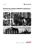
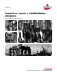
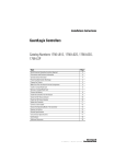
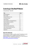
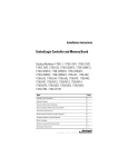
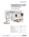
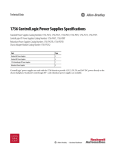
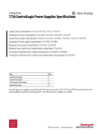
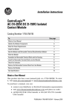
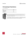
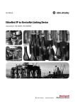
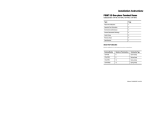
Technical Data
1788 Linking Device Specifications
Catalog Numbers 1788-EN2DNR, 1788-EN2FFR, 1788-EN2PAR, 1788-CN2DN, 1788-CN2FFR, 1788-CN2PAR, 1788-FBJB4R, 1788-FBJB6
Topic
Page
1788-EN2DNR EtherNet/IP to DeviceNet Linking Device
2
1788-CN2DN ControlNet to DeviceNet Linking Device
4
Linking Devices to FOUNDATION Fieldbus Networks
6
FOUNDATION Fieldbus Junction Boxes
8
Linking Devices to Profibus PA Networks
10
Additional Resources
12
1788 Linking Device Specifications
1788-EN2DNR EtherNet/IP to DeviceNet Linking Device
The 1788-EN2DNR linking device connects an EtherNet/IP network to a DeviceNet network.
Technical Specifications - 1788-EN2DNR
Attribute
1788-EN2DNR
Power requirements
Input: 24V DC, 150 mA, Class 2/SELV
DeviceNet: 24V DC, 60 mA, Class 2/SELV
Isolation voltage
30V (continuous), basic insulation type, power to system, Ethernet to system, DeviceNet to system, and USB to
system.
Type tested at 500V AC for 60 s.
Ethernet connection
RJ45 connector according to IEC 60603-7, 2 or 4 pair Category 5e minimum cable according to TIA 568-B.1 or
Category 5 cable according to ISO/IEC 24702.
DeviceNet connection(1)
0.52 mm2 (20 AWG), 1485C-P1-Cxxx.
Power connection
Power: 0.25…2.5 mm2 (22…14 AWG) solid or stranded copper wire rated at 105 °C (221 °F ), or greater, 1.2 mm
(3/64 in.) insulation max.
Wiring category(2)
2 - on power ports
2 - on communication ports
North American temperature code
T4
IEC temperature code
T4
(1) Refer to DeviceNet Media Design Installation Guide, publication DNET-UM072.
(2) Use this Conductor Category information for planning conductor routing. Refer to Industrial Automation Wiring and Grounding Guidelines, publication 1770-4.1.
Environmental Specifications - 1788-EN2DNR
2
Attribute
1788-EN2DNR
Temperature, operating
IEC 60068-2-1 (Test Ad, Operating Cold),
IEC 60068-2-2 (Test Bd, Operating Dry Heat),
IEC 60068-2-14 (Test Nb, Operating Thermal Shock)
-25…60 °C (-13…140 °F)
Temperature, surrounding air, max.
60 °C (140 °F)
Temperature, nonoperating
IEC 60068-2-1 (Test Ab, Unpackaged Nonoperating Cold),
IEC 60068-2-2 (Test Bb, Unpackaged Nonoperating Dry Heat),
IEC 60068-2-14 (Test Na, Unpackaged Nonoperating Thermal Shock)
-40…85 °C (-40…185 °F)
Relative humidity
IEC 60068-2-30 (Test Db, Unpackaged Damp Heat)
5…95% noncondensing
Shock, operating
IEC 60068-2-27 (Test Ea, Unpackaged Shock)
30 g
Shock, nonoperating
IEC 60068-2-27 (Test Ea, Unpackaged Shock)
50 g
Vibration
IEC 60068-2-6 (Test Fc, Operating)
2 g @ 10…500 Hz
Emissions
CISPR 11 (IEC 61000-6-4)
Class A
Rockwell Automation Publication 1788-TD001A-EN-P - July 2014
1788 Linking Device Specifications
Attribute
1788-EN2DNR
ESD Immunity
IEC 61000-4-2
6 kV contact discharge
8 kV air discharge
Conducted RF Immunity
IEC 61000-4-6
10 V rms with 1 kHz sine-wave 80% AM from 150 kHz…80 MHz
Radiated RF Immunity
IEC 61000-4-3
10 V/m with 1 kHz sine-wave 80% AM from 80…1000 MHz and 1400…2000 MHz
10 V/m with 200 Hz 50% Pulse 100% AM @ 900 MHz
10 V/m with 200 Hz 50% Pulse 100% AM @ 1890 MHz
1 V/m with 1 kHz sine-wave 80% AM from 2000…2700 MHz
EFT/B Immunity
IEC 61000-4-4
±3 kV at 5 kHz on power ports
±3 kV at 5 kHz on communication ports
Surge Transient Immunity
IEC 61000-4-5
±500V line-line (DM) and ±1 kV line-earth (CM) on power ports
±2 kV line-earth (CM) on communication ports
Voltage variation
IEC 61000-4-29
10 ms interruption on DC power port
Certifications - 1788-EN2DNR
Certification (when product is marked)(1)
1788-EN2DNR
c-UL-us
UL Listed for Class I, Division 2 Group A,B,C,D Hazardous Locations, certified for U.S. and Canada. See UL File E194810.
CE
European Union 2004/108/EC EMC Directive, compliant with:
• EN 61326-1: Meas./Control/Lab., Industrial Requirements
• EN 61000-6-2: Industrial Immunity
• EN 61000-6-4: Industrial Emissions
• EN 61131-2: Programmable Controllers (Clause 8, Zone A and B)
European Union 2011/65/EU RoHS, compliant with:
• EN 50581; Technical Documentation
RCM
Australian Radiocommunications Act, compliant with:
• EN 61000-6-4; Industrial Emissions
Ex
European Union 94/9/EC ATEX Directive, compliant with:
• EN 60079-15; Potentially Explosive Atmospheres, Protection "n"
• EN 60079-0; General Requirements II 3 G Ex nA IIC T4 Gc X
KC
Korean Registration of Broadcasting and Communications Equipment, compliant with:
• Article 58-2 of Radio Waves Act, Clause 3
EtherNet /IP
ODVA conformance tested to EtherNet/IP specifications
DeviceNet
ODVA conformance tested to DeviceNet specifications
(1) See the Product Certification link at http://www.ab.com for declarations of conformity, certificates, and other certification details.
Rockwell Automation Publication 1788-TD001A-EN-P - July 2014
3
1788 Linking Device Specifications
1788-CN2DN ControlNet to DeviceNet Linking Device
The 1788-CN2DN linking device connects a ControlNet network to a DeviceNet network.
Technical Specifications - 1788-CN2DN
Attribute
1788-CN2DN
Power requirements
Input: 24V DC, 500 mA
DeviceNet: 24V DC, 90 mA, Class 2
Isolation voltage
30V (continuous), basic insulation type, between all ports.
Type tested at 720V DC for 60 s.
ControlNet connection
RG6
DeviceNet connection(1)
0.52 mm2 (20 AWG), 1485C-P1-Cxxx.
Power connection
Power: 0.25…2.5 mm2 (22…14 AWG) solid or stranded copper wire rated at 75 °C (167 °F ), or greater, 1.2 mm
(3/64 in.) insulation max.
Wiring category(2)
3 - on power ports
2 - on communication ports
Dimensions (H x W x D), approx.
120 x 200 x 87 mm (4 11/16 x 7 7/8 x 3 7/16 in.)
Enclosure type rating
None (open-style)
North American temperature code
T4A
IEC temperature code
T4
(1) Refer to DeviceNet Media Design Installation Guide, publication DNET-UM072.
(2) Use this Conductor Category information for planning conductor routing. Refer to Industrial Automation Wiring and Grounding Guidelines, publication 1770-4.1.
Environmental Specifications - 1788-CN2DN
4
Attribute
1788-CN2DN
Temperature, operating
IEC 60068-2-1 (Test Ad, Operating Cold),
IEC 60068-2-2 (Test Bd, Operating Dry Heat),
IEC 60068-2-14 (Test Nb, Operating Thermal Shock)
0…60 °C (32…140 °F)
Temperature, surrounding air, max.
60 °C (140 °F)
Temperature, nonoperating
IEC 60068-2-1 (Test Ab, Unpackaged Nonoperating Cold),
IEC 60068-2-2 (Test Bb, Unpackaged Nonoperating Dry Heat),
IEC 60068-2-14 (Test Na, Unpackaged Nonoperating Thermal Shock)
-40…85 °C (-40…185 °F)
Relative humidity
IEC 60068-2-30 (Test Db, Unpackaged Damp Heat)
5…95% noncondensing
Shock, operating
IEC 60068-2-27 (Test Ea, Unpackaged Shock)
30 g
Shock, nonoperating
IEC 60068-2-27 (Test Ea, Unpackaged Shock)
50 g
Vibration
IEC 60068-2-6 (Test Fc, Operating)
2 g @ 10…500 Hz
Rockwell Automation Publication 1788-TD001A-EN-P - July 2014
1788 Linking Device Specifications
Attribute
1788-CN2DN
Emissions
CISPR 11 (IEC 61000-6-4)
Class A
ESD Immunity
IEC 61000-4-2
6 kV contact discharge
8 kV air discharge
Conducted RF immunity
IEC 61000-4-6
10 V rms with 1 kHz sine-wave 80% AM from 150 kHz…80 MHz
Radiated RF immunity
IEC 61000-4-3
10 V/m with 1 kHz sine-wave 80% AM from 30…2000 MHz
10 V/m with 200 Hz 50% Pulse 100% AM @ 900 MHz
10 V/m with 200 Hz 50% Pulse 100% AM @ 1890 MHz
3 V/m with 1 kHz sine-wave 80% AM from 2000…2700 MHz
EFT/B immunity
IEC 61000-4-4
±4 kV at 5 kHz on power ports
±3 kV at 5 kHz on communication ports
Surge Transient immunity
IEC 61000-4-5
±2 kV line-earth (CM) on communication ports
Certifications - 1788-CN2DN
Certification (when product is marked)(1)
1788-CN2DN
c-UL-us
UL Listed Industrial Control Equipment, certified for US and Canada. See UL File E65584.
UL Listed for Class I, Division 2 Group A,B,C,D Hazardous Locations, certified for U.S. and Canada. See UL File
E194810.
CSA
CSA Certified Process Control Equipment. See CSA File LR54689C.
CSA Certified Process Control Equipment for Class I, Division 2 Group A,B,C,D Hazardous Locations. See CSA File
LR69960C.
CE
European Union 2004/108/EC EMC Directive, compliant with:
• EN 61326-1: Meas./Control/Lab., Industrial Requirements
• EN 61000-6-2: Industrial Immunity
• EN 61000-6-4: Industrial Emissions
• EN 61131-2: Programmable Controllers (Clause 8, Zone A and B)
C-Tick
Australian Radiocommunications Act, compliant with:
• AS/NZS CISPR 11; Industrial Emissions
Ex
European Union 94/9/EC ATEX Directive, compliant with:
• EN 60079-15; Potentially Explosive Atmospheres, Protection "n"
• EN 60079-0; General Requirements I 3 G Ex nA IIC T4X Gc
DeviceNet
ODVA conformance tested to DeviceNet specifications
CI
ControlNet Int'l conformance tested to ControlNet specifications.
(1) See the Product Certification link at http://www.ab.com for declarations of conformity, certificates, and other certification details.
Rockwell Automation Publication 1788-TD001A-EN-P - July 2014
5
1788 Linking Device Specifications
Linking Devices to FOUNDATION Fieldbus Networks
The 1788-EN2FFR linking device provides a gateway between EtherNet/IP and FOUNDATION Fieldbus networks.
The 1788-CN2FFR linking device provides a gateway between ControlNet and FOUNDATION Fieldbus networks.
Technical Specifications - 1788-EN2FFR, 1788-CN2FFR
Attribute
1788-EN2FFR, 1788-CN2FFR
Power requirements
Input: 24…32V DC, 0.75 A, Class 2/SELV
Foundation Fieldbus (FF): 0.5 A @24V DC single trunk; 0.4 A @ 24V DC dual trunk
Power is connected to the linking device by using the 2-way Phoenix connector.
Power consumption
260 mA at 24 V (with no field devices attached)
Power dissipation
12.24 W at 24V DC
Isolation voltage
30V (continuous), basic insulation type, network channels to power, and network channels to network channels.
No isolation between redundant network channels.
Type tested at 500V DC for 60 s.
Ethernet conductors
CAT5 STP/UTP
Terminal torque
DC Power connections: 0.22…0.25 N•m (2…2.2 lb•in)
Fieldbus connections: 0.5…0.6 N•m (4.4…5.3 lb•in)
Wire size
DC power and Foundation Fieldbus connections:
0.205... 0.823 mm2 (24…18 AWG) solid or stranded copper wire rated at 82 °C (180 °F) or greater
1.2 mm (3/64 in.) insulation max
Wiring category(1)
1 - on power ports
2 - on ControlNet, Ethernet, and Foundation Fieldbus ports
Enclosure type rating
None (open-style)
North American temperature code
T4
IEC temperature code
T4
(1) Use this Conductor Category information for planning conductor routing. Refer to Industrial Automation Wiring and Grounding Guidelines, publication 1770-4.1.
Environmental Specifications - 1788-EN2FFR, 1788-CN2FFR
6
Attribute
1788-EN2FFR, 1788-CN2FFR
Temperature, operating
IEC 60068-2-1 (Test Ad, Operating Cold),
IEC 60068-2-2 (Test Bd, Operating Dry Heat),
IEC 60068-2-14 (Test Nb, Operating Thermal Shock)
0…60 °C (32…140 °F)
Temperature, surrounding air, max.
60 °C (140 °F)
Temperature, nonoperating
IEC 60068-2-1 (Test Ab, Unpackaged Nonoperating Cold),
IEC 60068-2-2 (Test Bb, Unpackaged Nonoperating Dry Heat),
IEC 60068-2-14 (Test Na, Unpackaged Nonoperating Thermal Shock)
0…60 °C (32…140 °F)
Relative humidity
IEC 60068-2-30 (Test Db, Unpackaged Damp Heat)
5…95% noncondensing
Rockwell Automation Publication 1788-TD001A-EN-P - July 2014
1788 Linking Device Specifications
Attribute
1788-EN2FFR, 1788-CN2FFR
Shock, operating
IEC 60068-2-27 (Test Ea, Unpackaged Shock)
15 g
Shock, nonoperating
IEC 60068-2-27 (Test Ea, Unpackaged Shock)
30 g
Vibration
IEC 60068-2-6 (Test Fc, Operating)
0.5 g @ 10…500 Hz
Emissions
CISPR 11 (IEC 61000-6-4)
Class A
ESD Immunity
IEC 61000-4-2
6 kV contact discharge
8 kV air discharge
Conducted RF immunity
IEC 61000-4-6
10 V rms with 1 kHz sine-wave 80% AM from 150 kHz…80 MHz
Radiated RF immunity
IEC 61000-4-3
10 V/m with 1 kHz sine-wave 80% AM from 80…2000 MHz
10 V/m with 200 Hz 50% Pulse 100% AM @ 900 MHz
10 V/m with 200 Hz 50% Pulse 100% AM @ 1890 MHz
3 V/m with 1 kHz sine-wave 80% AM from 2000…2700 MHz
EFT/B immunity
IEC 61000-4-4
±4 kV at 5 kHz on power ports
±3 kV at 5 kHz on Ethernet and FF ports
Surge Transient immunity
IEC 61000-4-5
±1 kV line-line (DM) and ±2 kV line-earth (CM) on power ports
±1 KV line-earth (CM) on ControlNet ports
±2 kV line-earth (CM) on Ethernet and FF ports
Certifications - 1788-EN2FFR, 1788-CN2FFR
Certification (when product is marked)(1)
1788-EN2FFR, 1788-CN2FFR
c-UL-us
UL Listed Industrial Control Equipment, certified for US and Canada. See UL File E320594.
UL Listed for Class I, Division 2 Group A,B,C,D Hazardous Locations, certified for U.S. and Canada. See UL File E320595.
CE
European Union 2004/108/EC EMC Directive, compliant with:
• EN 61326-1: Meas./Control/Lab., Industrial Requirements
• EN 61000-6-2: Industrial Immunity
• EN 61000-6-4: Industrial Emissions
• EN 61131-2: Programmable Controllers (Clause 8, Zone A and B)
RCM
Australian Radiocommunications Act, compliant with:
• EN 61000-6-4; Industrial Emissions
Ex
European Union 94/9/EC ATEX Directive, compliant with:
• EN 60079-15; Potentially Explosive Atmospheres, Protection "n"
• EN 60079-0; General Requirements II 3 G Ex nA IIC T4 Gc X
KC
Korean Registration of Broadcasting and Communications Equipment, compliant with:
• Article 58-2 of Radio Waves Act, Clause 3
EtherNet /IP
ODVA conformance tested to EtherNet/IP specifications
FF
Foundation Fieldbus Test Campaign Number: CT0152FF
(1) See the Product Certification link at http://www.ab.com for declarations of conformity, certificates, and other certification details.
Rockwell Automation Publication 1788-TD001A-EN-P - July 2014
7
1788 Linking Device Specifications
FOUNDATION Fieldbus Junction Boxes
The 1788-FBJB4R and 1788-FBJB6 junction boxes provide connections to FOUNDATION Fieldbus networks.
Technical Specifications - 1788-FBJB4R, 1788-FBJB6
Attribute
1788-FBJB4R
1788-FBJB6
Power requirements
Input: 12…32V DC, 0.5 A, Class 2/SELV
Trunk output: 12…32V DC, 0.36 A, resistive only
Drop output: 12…32V DC, 40 mA, resistive only
Input: 12…32V DC, 0.5 A, Class 2/SELV
Trunk output: 12…32V DC, 0.48 A, resistive only
Drop output: 12…32V DC, 40 mA, resistive only
Power consumption
40 mA at 24 V max.
Isolation voltage
No isolation between communication channels
Conductor temperature rating
> 82 °C (180 °F)
Terminal torque
0.5…0.6 N•m (4.4…5.3 lb•in)
Wire size
DC power and Foundation Fieldbus connections:
0.205... 0.823 mm2 (24…18 AWG) solid or stranded copper wire rated at 82 °C (180 °F) or greater
1.2 mm (3/64 in.) insulation max
Wiring category(1)
2 - on communication ports
Enclosure type rating
None (open-style)
North American temperature code
T4
IEC temperature code
T4
(1) Use this Conductor Category information for planning conductor routing. Refer to Industrial Automation Wiring and Grounding Guidelines, publication 1770-4.1.
Environmental Specifications - 1788-FBJB4R, 1788-FBJB6
8
Attribute
1788-FBJB4R, 1788-FBJB6
Temperature, operating
IEC 60068-2-1 (Test Ad, Operating Cold),
IEC 60068-2-2 (Test Bd, Operating Dry Heat),
IEC 60068-2-14 (Test Nb, Operating Thermal Shock)
0…60 °C (32…140 °F)
Temperature, surrounding air, max.
60 °C (140 °F)
Temperature, nonoperating
IEC 60068-2-1 (Test Ab, Unpackaged Nonoperating Cold),
IEC 60068-2-2 (Test Bb, Unpackaged Nonoperating Dry Heat),
IEC 60068-2-14 (Test Na, Unpackaged Nonoperating Thermal Shock)
0…60 °C (32…140 °F)
Relative humidity
IEC 60068-2-30 (Test Db, Unpackaged Damp Heat)
5…95% noncondensing
Shock, operating
IEC 60068-2-27 (Test Ea, Unpackaged Shock)
15 g
Shock, nonoperating
IEC 60068-2-27 (Test Ea, Unpackaged Shock)
30 g
Vibration
IEC 60068-2-6 (Test Fc, Operating)
0.5 g @ 10…500 Hz
Emissions
CISPR 11 (IEC 61000-6-4)
Class A
Rockwell Automation Publication 1788-TD001A-EN-P - July 2014
1788 Linking Device Specifications
Attribute
1788-FBJB4R, 1788-FBJB6
ESD immunity
IEC 61000-4-2
6 kV contact discharge
8 kV air discharge
Conducted RF immunity
IEC 61000-4-6
10 V rms with 1 kHz sine-wave 80% AM from 150 kHz…80 MHz
Radiated RF immunity
IEC 61000-4-3
10 V/m with 1 kHz sine-wave 80% AM from 80…2000 MHz
10 V/m with 200 Hz 50% Pulse 100% AM @ 900 MHz
10 V/m with 200 Hz 50% Pulse 100% AM @ 1890 MHz
3 V/m with 1 kHz sine-wave 80% AM from 2000…2700 MHz
EFT/B immunity
IEC 61000-4-4
±3 kV at 5 kHz on communication ports
Surge Transient immunity
IEC 61000-4-5
±2 kV line-earth (CM) on communication ports
Certifications - 1788-FBJB4R, 1788-FBJB6
Certification (when product is marked)(1)
1788-FBJB4R, 1788-FBJB6
c-UR-us
UL Recognized Component Industrial Control Equipment, certified for US and Canada. See UL File E320594.
UL Recognized Component Industrial Control Equipment for Class I, Division 2 Group A,B,C,D Hazardous Locations,
certified for US and Canada. See UL File E320595.
CE
European Union 2004/108/EC EMC Directive, compliant with:
• EN 61326-1: Meas./Control/Lab., Industrial Requirements
• EN 61000-6-2: Industrial Immunity
• EN 61000-6-4: Industrial Emissions
• EN 61131-2: Programmable Controllers (Clause 8, Zone A and B)
RCM
Australian Radiocommunications Act, compliant with:
• EN 61000-6-4; Industrial Emissions
Ex
European Union 94/9/EC ATEX Directive, compliant with:
• EN 60079-15; Potentially Explosive Atmospheres, Protection "n"
• EN 60079-0; General Requirements II 3 G Ex nA IIC T4 Gc X
KC
Korean Registration of Broadcasting and Communications Equipment, compliant with:
• Article 58-2 of Radio Waves Act, Clause 3
(1) See the Product Certification link at http://www.ab.com for declarations of conformity, certificates, and other certification details.
Rockwell Automation Publication 1788-TD001A-EN-P - July 2014
9
1788 Linking Device Specifications
Linking Devices to Profibus PA Networks
The 1788-EN2PAR linking device provides a gateway between EtherNet/IP and Profibus PA networks.
The 1788-CN2PAR linking device provides a gateway between ControlNet and Profibus PA networks.
Technical Specifications - 1788-EN2PAR, 1788-CN2PAR
Attribute
1788-EN2PAR, 1788-CN2PAR
Power requirements
Input: 24…32V DC, 0.75 A, Class 2/SELV
PA: 0.5 A @ 24V DC single trunk; 0.4 A @ 24V DC dual trunk
Power is connected to the linking device by using the 4-way Phoenix connector.
Power consumption
260 mA at 24 V (with no field devices attached)
Power dissipation
12.24 W at 24V DC
Isolation voltage
30V (continuous), basic insulation type, network channels to power, and network channels to network channels.
No isolation between redundant network channels.
Type tested at 500V DC for 60 s.
Ethernet conductors
CAT5 STP/UTP
Terminal torque
DC Power connections: 0.22…0.25 N•m (2…2.2 lb•in)
Profibus PA connections: 0.5…0.6 N•m (4.4…5.3 lb•in)
Wire size
DC power and Profibus PA connections:
0.205... 0.823 mm2 (24...18 AWG) solid or stranded copper wire rated at 82 °C (180 °F) or greater
1.2 mm (3/64 in.) insulation max
Wiring category(1)
1 - on power ports
2 - on ControlNet, Ethernet, and Foundation Fieldbus ports
Enclosure type rating
None (open-style)
North American temperature code
T4
IEC temperature code
T4
(1) Use this Conductor Category information for planning conductor routing. Refer to Industrial Automation Wiring and Grounding Guidelines, publication 1770-4.1.
Environmental Specifications - 1788-EN2PAR, 1788-CN2PAR
Attribute
1788-EN2PAR, 1788-CN2PAR
Temperature, operating
IEC 60068-2-1 (Test Ad, Operating Cold),
IEC 60068-2-2 (Test Bd, Operating Dry Heat),
IEC 60068-2-14 (Test Nb, Operating Thermal Shock)
0…60 °C (32…140 °F)
Temperature, surrounding air, max.
60 °C (140 °F)
Temperature, nonoperating
IEC 60068-2-1 (Test Ab, Unpackaged Nonoperating Cold),
IEC 60068-2-2 (Test Bb, Unpackaged Nonoperating Dry Heat),
IEC 60068-2-14 (Test Na, Unpackaged Nonoperating Thermal Shock)
0…60 °C (32…140 °F)
Relative humidity
IEC 60068-2-30 (Test Db, Unpackaged Damp Heat)
5…95% noncondensing
10
Rockwell Automation Publication 1788-TD001A-EN-P - July 2014
1788 Linking Device Specifications
Attribute
1788-EN2PAR, 1788-CN2PAR
Shock, operating
IEC 60068-2-27 (Test Ea, Unpackaged Shock)
15 g
Shock, nonoperating
IEC 60068-2-27 (Test Ea, Unpackaged Shock)
30 g
Vibration
IEC 60068-2-6 (Test Fc, Operating)
0.5 g @ 10…500 Hz
Emissions
CISPR 11 (IEC 61000-6-4)
Class A
ESD immunity
IEC 61000-4-2
6 kV contact discharge
8 kV air discharge
Conducted RF immunity
IEC 61000-4-6
10 V rms with 1 kHz sine-wave 80% AM from 150 kHz…80 MHz
Radiated RF immunity
IEC 61000-4-3
10 V/m with 1 kHz sine-wave 80% AM from 80…2000 MHz
10 V/m with 200 Hz 50% Pulse 100% AM @ 900 MHz
10 V/m with 200 Hz 50% Pulse 100% AM @ 1890 MHz
3 V/m with 1 kHz sine-wave 80% AM from 2000…2700 MHz
EFT/B immunity
IEC 61000-4-4
±4 kV at 5 kHz on power ports
±3 kV at 5 kHz on Ethernet and FF ports
Surge Transient immunity
IEC 61000-4-5
±1 kV line-line (DM) and ±2 kV line-earth (CM) on power ports
±1 KV line-earth (CM) on ControlNet ports
±2 kV line-earth (CM) on Ethernet and FF ports
Certifications - 1788-EN2PAR, 1788-CN2PAR
Certification (when product is marked)(1)
1788-EN2PAR, 1788-CN2PAR
c-UL-us
UL Listed Industrial Control Equipment, certified for US and Canada. See UL File E320594.
UL Listed for Class I, Division 2 Group A,B,C,D Hazardous Locations, certified for U.S. and Canada. See UL File E320595.
CE
European Union 2004/108/EC EMC Directive, compliant with:
• EN 61326-1: Meas./Control/Lab., Industrial Requirements
• EN 61000-6-2: Industrial Immunity
• EN 61000-6-4: Industrial Emissions
• EN 61131-2: Programmable Controllers (Clause 8, Zone A and B)
RCM
Australian Radiocommunications Act, compliant with:
• EN 61000-6-4; Industrial Emissions
Ex
European Union 94/9/EC ATEX Directive, compliant with:
• EN 60079-15; Potentially Explosive Atmospheres, Protection "n"
• EN 60079-0; General Requirements II 3 G Ex nA IIC T4 Gc X
KC
Korean Registration of Broadcasting and Communications Equipment, compliant with:
• Article 58-2 of Radio Waves Act, Clause 3
EtherNet /IP
ODVA conformance tested to EtherNet/IP specifications
(1) See the Product Certification link at http://www.ab.com for declarations of conformity, certificates, and other certification details.
Rockwell Automation Publication 1788-TD001A-EN-P - July 2014
11
1788 Linking Device Specifications
Additional Resources
These documents contain additional information concerning related products from Rockwell Automation.
Resource
Description
EtherNet/IP to DeviceNet Linking Device User Manual, publication 1788-UM059
Provides information on installing and using the 1788-EN2DNR linking device.
ControlNet-to-DeviceNet Linking Device Installation Instructions, publication 1788-IN052
Provides information on installing and using the 1788-CN2DN linking device.
EtherNet/IP and ControlNet to FOUNDATION Fieldbus Linking Devices User Manual,
publication 1788-UM057
Provides information on the installation and operation of the 1788-EN2FFR
and 1788-CN2FFR linking devices.
EtherNet/IP and ControlNet to PROFIBUS PA Linking Device User Manual, publication
1788-UM058
Provides information on the installation and operation of the 1788-EN2PAR
and 1788-CN2PAR linking devices.
Industrial Automation Wiring and Grounding Guidelines, publication 1770-4.1
Provides general guidelines for installing a Rockwell Automation® industrial system.
Product Certifications website, http://www.ab.com
Provides declarations of conformity, certificates, and other certification details.
You can view or download publications at http://www.rockwellautomation.com/literature/. To order paper copies of
technical documentation, contact your local Allen-Bradley distributor or Rockwell Automation sales representative.
12
Rockwell Automation Publication 1788-TD001A-EN-P - July 2014
1788 Linking Device Specifications
Notes:
Rockwell Automation Publication 1788-TD001A-EN-P - July 2014
13
Important User Information
Solid-state equipment has operational characteristics differing from those of electromechanical equipment. Safety
Guidelines for the Application, Installation and Maintenance of Solid State Controls (publication SGI-1.1 available from
your local Rockwell Automation sales office or online at http://www.rockwellautomation.com/literature/) describes some
important differences between solid-state equipment and hard-wired electromechanical devices. Because of this difference,
and also because of the wide variety of uses for solid-state equipment, all persons responsible for applying this equipment
must satisfy themselves that each intended application of this equipment is acceptable.
In no event will Rockwell Automation, Inc. be responsible or liable for indirect or consequential damages resulting from the
use or application of this equipment.
The examples and diagrams in this publication are included solely for illustrative purposes. Because of the many variables
and requirements associated with any particular installation, Rockwell Automation, Inc. cannot assume responsibility or
liability for actual use based on the examples and diagrams.
No patent liability is assumed by Rockwell Automation, Inc. with respect to use of information, circuits, equipment, or
software described in this manual.
Reproduction of the contents of this manual, in whole or in part, without written permission of Rockwell Automation,
Inc., is prohibited.
Documentation Feedback
Your comments will help us serve your documentation needs better. If you have any suggestions on how to improve this
document, complete this form, publication RA-DU002, available at http://www.rockwellautomation.com/literature/.
Allen-Bradley, Rockwell Software, Rockwell Automation, and LISTEN. THINK. SOLVE are trademarks of Rockwell Automation, Inc.
Trademarks not belonging to Rockwell Automation are property of their respective companies.
Rockwell Otomasyon Ticaret A.Ş., Kar Plaza İş Merkezi E Blok Kat:6 34752 İçerenköy, İstanbul, Tel: +90 (216) 5698400
Publication 1788-TD001A-EN-P - July 2014
Supersedes Publication XXXX-X.X.X - Month Year
Copyright © 2014 Rockwell Automation, Inc. All rights reserved. Printed in the U.S.A.