1
Connectors and Switches on the Back of Your Cable Modem
23
Connectors and Switches on the Back of Your Cable
Modem
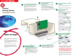
The following paragraphs are numbered so that they refer
to the diagram below.
1 Cable RF Connector: This is where you connect the
coaxial cable that leads to your splitter or your cable wall
jack.
2 RJ-45 Jack: This is where you plug the included RJ-45
Ethernet cable. The other end connects to the RJ-45 jack
on your NIC or to the RJ-45 jack on your USB network
interface, depending on the type of installation you chose.
3 Power Jack: This is where you plug in the power adapter
that came with your cable modem. Remember to use only
the power supply that came with your cable modem.
3
2
1