1
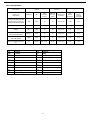
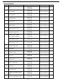
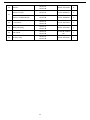
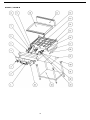
Thor Gas Griddle Installation and Operation Instructions Model: GL167-P , GL167-N, GL168-P , GL168-N IMPORTANT FOR FUTURE REFERENCE Please complete this information and retain this manual for the life of the equipment. For Warranty Service and/or parts, this information is required. Model Number Serial Number Date Purchased WARNING: For your safety, do not store or use gasoline or other flammable vapors or liquids in the vicinity of this or any other appliances. Keep the area free and clear of combustible materials. WARNING:Improper installation, adjustment, alteration, service or maintenance can cause property damage, injury, or death. Read the installation operating and maintenance instructions thoroughly before installing, or servicing this equipment. WARNING : Instructions must be posted in a prominent location. All safety precautions must be taken in the event the user smells gas. Safety information can be obtained from your local gas supplier. Fourth Way, Avonmouth, Bristol, BS11 8TB Contents Introduction ............................................................................................. 2 Specifications ........................................................................................... 3 General Pack Contents Gas Supply Requirements Dimensions ................................................................................................ 4 Installation ................................................................................................ 5 Installation Requirements Unpacking Location Clearances Assembly Gas Connection Commissioning Install gas stand Operation .................................................................................................. 10 Operation Guide Lighting the Main Burner Cleaning and Maintenance ............................................................................ 14 Routine Maintenance After Each Use Daily Cleaning Weekly Cleaning Trouble Shooting..........................................................................................16 Replacement Parts List .........................................................................…..…17 Gas Conversion …………........................................................................…......18 Explosion Drawing ..............................................................................…....…22 Spare Parts List ............................................................................................22 Declaration Of Conformity...............................................................................27 Introduction We are confident that you will be delighted with your Thor Gas Griddle, and it will become a most valued appliance in your commercial kitchen. To ensure you receive the utmost benefit from your new Gas Griddle, there are two important things you can do. Firstly: Please read the instruction book carefully and follow the directions given. The time taken will be well spent. Secondly: If you are unsure of any aspect of the installation, instructions or performance of your appliance, contact your dealer promptly. In many cases a phone call could answer your question. CE Only: These instructions are only valid if the country code appears on the appliance. If the code does not appear on the appliance, refer to the supplier of this appliance to obtain the technical instructions for adapting the appliance to the conditions for use in that country. WARNING: IMPROPER INSTALLATION, ADJUSTMENT, ALTERATION, SERVICE OR MAINTENANCE CAN CAUSE PROPERTY DAMAGE, INJURY OR DEATH. READ THE INSTALLATION, OPERATING AND MAINTENANCE INSTRUCTIONS THOROUGHLY BEFORE INSTALLING OR SERVICING THIS APPLIANCE. WARNING: INSTRUCTIONS TO BE FOLLOWED IN THE EVENT THE USER SMELLS GAS ARE TO BE POSTED IN A PROMINENT LOCATION. THIS INFORMATION SHALL BE OBTAINED BY CONSULTING THE LOCAL GAS SUPPLIER. WARNING: GREAT CARE MUST BE TAKEN BY THE OPERATOR TO USE THE EQUIPMENT SAFELY TO GUARD IT AGAINST RISK OF FIRE. • THE APPLIANCE MUST NOT BE LEFT ON UNATTENDED. • IT IS RECOMMENDED THAT A REGULAR INSPECTION IS MADE BY A COMPETENT SERVICE PERSON TO ENSURE CORRECT AND SAFE OPERATION OF YOUR APPLIANCE IS MAINTAINED. • DO NOT STORE OR USE GASOLINE OR OTHER FLAMMABLE VAPOURS OR LIQUIDS IN THE VICINITY OF THIS OR ANY OTHER APPLIANCE. • DO NOT SPRAY AEROSOLS IN THE VICINITY OF THIS APPLIANCE WHILE IT IS IN OPERATION. CAUTION: THIS APPLIANCE IS; • FOR PROFESSIONAL USE AND IS TO BE USED BY QUALIFIED PERSONS ONLY. • ONLY QUALIFIED SERVICE PERSONS ARE TO CARRY OUT INSTALLATION, SERVICING AND GAS CONVERSION OPERATIONS. • COMPONENTS HAVING ADJUSTMENTS PROTECTED BY THE MANUFACTURER SHOULD NOT BE ADJUSTED BY THE USER/OPERATOR. • DO NOT OPERATE THE APPLIANCE WITHOUT THE LEGS SUPPLIED FITTED. 2 Specifications General Commercial, heavy duty, gas griddle with full pilot and flame failure protection and piezo ignition. It uses a 19mm thick griddle smooth plate. Pack Contents The following is included: Thor Gas Griddle Gas Stand Instruction Manual Gas Supply Requirements Natural Gas(G20) Single burner Heat Input Heat Total Propane(G31) Butane(G30) Propane GL167-P GL168-P GL167-N GL168-N GL167-P GL168-P 8.8 KW 8.8KW 8.8 KW 8.8 KW 8.8 KW 8.8 KW 17.6 KW 26.4 KW 17.6 KW 26.4 KW 17.6 KW 26.4 KW Burner Operating Pressure 20 mbar 37 mbar 28-30 mbar Supply Pressure 20 mbar 37 mbar 28-30 mbar Gas Connection ¾” BSP Male ¾” BSP Male ¾” BSP Male The burner operating pressure is to be measured at the gas control valve outlet test point with one burner operating at ‘High’ setting. The operating pressure is ex-factory set, through the appliance regulator and not to be adjusted. Minimum input Heat of burner: 5.8KW for Propane or Butane , 5.3KW for Natural Gas. 3 Dimensions GL167-P / GL167-N GL168-P / GL168-N 4 Installation Installation Requirements NOTE: • It is most important that this appliance is installed correctly and that operation is correct before use. Installation shall comply with local gas, health and safety requirements. • This appliance shall be installed with sufficient ventilation to prevent the occurrence of unacceptable concentrations of substances harmful to health. Our Gas Griddles are designed to provide years of satisfactory service and correct installation is essential to achieve the best performance, efficiency and trouble-free operation. This appliance must be installed in accordance with National installation codes and in addition, in accordance with relevant National / Local codes covering gas and fire safety. Australia: AS 5601/AG 601 (to be AS 5601)- Gas Installations New Zealand: NZS 5261 - Gas Installation. United Kingdom: Gas Safety (Installation and Use) Regulations 1998 BS 6173-Installation of Catering Appliances. BS 5440-1&2 Installation Flueing & Ventilation. Ireland: IS 820-Non Domestic Gas Installations. Installations must be carried out by qualified persons only. Failure to install equipment to the relevant codes and manufacturer’s specifications shown in this section will void the warranty. Components having adjustments protected by the manufacturer are only to be adjusted by an authorized service agent. They are not to be adjusted by the installation person. Unpacking • Remove all packaging and transit protection from the appliance including all protective plastic coating from the exterior stainless steel panels. • Check equipment and parts for damage. Report any damage immediately to the carrier and distributor. • Report any deficiencies to the distributor who supplied the appliance. • Check that the available gas supply is correct to that shown on the rating plate located on the right hand panel. Location 1. Installation must allow for a sufficient flow of fresh air for the combustion air supply. 2. Installation must include adequate ventilation means, to prevent dangerous build-up of combustion products. Any gas burning appliance requires adequate clearance and ventilation for optimum and trouble-free operation. The minimum installation clearances shown below are to be adhered to. Position the appliance in its approximate working position. All air for burner combustion is supplied from underneath the unit. The legs must always be fitted and no obstructions placed on the underside or around the base of the unit, as obstructions will cause incorrect operation and / or failure of the appliance. Components having adjustments protected by manufacturer are only allowed to be adjusted by an authorized service agent. They are not to be adjusted by the installation person. 3. 4. 5. 6. 5 Installation Clearances NOTE: Only non-combustible materials can be used in close proximity to this appliance. Combustible Surface Non Combustible Surface Left / Right Hand Side 250mm 0mm Rear 250mm 0mm Assembly NOTE: • This appliance is supplied with adjustable stand to enable the appliance to be positioned securely and level. This should be carried out on completion of the gas connection. Refer to the ‘Gas Connection’ section. Gas Connection NOTE: ALL GAS FITTING MUST ONLY BE CARRIED OUT BY A QUALIFIED PERSON. 1. 2. The Gas Griddles do not require an electrical connection, as they function totally on the gas supply only. It is essential that the gas supply is correct for the appliance to be installed and that adequate supply pressure and volume are available. The following checks should therefore be made before installation:a. Gas Type required for the appliance is shown in the rating label. Check that this is correct for the gas supply the appliance is being installed for. The gas conversion procedure is detailed in this manual. b. Supply Pressure required for this appliance is shown in the ‘Gas supply requirements’ section of this manual. Check the gas supply to ensure adequate supply pressure exists. c. Input Rate of this appliance is stated on the Rating label .The input rate should be checked against the available gas supply line capacity. Particular note should be taken if the appliance is being added to an existing installation. NOTE: It is important that adequately sized piping runs directly to the connection joint on the appliance with as few tees and elbows as possible to give maximum supply volume. NOTE: Ensure the regulator is converted to the correct gas type that the appliance will operate on. The regulator outlet pressure is fixed ex-factory for the gas type . 3. 4. 5. Correctly locate the appliance into its final operating position and using a spirit level, adjust the legs so that the unit is level and at the correct height. Connect the gas supply to the appliance through the regulator. (refer to the picture of “Install the Regulator”). A suitable jointing compound which resists the breakdown action of propane must be used on every gas line connection, unless compression fittings are used. Check all gas connections for leakages. WARNING: DO NOT USE A NAKED FLAME TO CHECK FOR GAS LEAKAGES. 6 Installation 6. Check that the gas operating pressure. NOTE: The operating pressure is to be measured at the burner operating pressure test point outlet and with one griddle burner operating at the “High Flame” setting. 7. 8. 9. Turn off the mains gas supply and bleed the gas out of the appliance gas lines. Turn on the gas supply and the appliance. Verify the operating pressure remains correct. Commissioning 1. Before leaving the new installation; a. Check the following functions in accordance with the operating instructions specified in the ‘Operation’ section of this manual. • Light the Pilot Burner. • Light the Main Burner. • Turning 'Off' the Main Burner/Pilot. b. Ensure that the operator has been instructed in the areas of correct lighting, operation, and shutdown procedure for the appliance. 2. This manual must be kept by the owner for future reference and a record of the Date of Purchase, Date of Installation and the Serial Number of the Appliance must be recorded and kept with this manual. (These details can be found on the Rating label, refer to the ‘Gas Connection’ section). NOTE: If for some reason it is not possible to get the appliance to operate correctly, shut off the gas supply and contact the supplier of this appliance. 7 Installation Install gas stand Remove the Stand from the packaging, ensuring that all protective packaging, plastic and residues are cleaned from its surfaces. Layout all components of the stand on the floor ready for assembly. You will need a screw-driver to assist in the assembly process Step 1 – Disconnect, remove griddle plate , upturn and support your gas equipment, taking care as items may be heavy. Screw the stand support assembly into the gas equipment. Stand support assembly Step 2 – Slot the base plate assembly into the stand support. Base plate assembly 8 Installation Step 3 – Fix and tighten the screws. Fixing screws Step 4 – Locate the stand into required position, and adjust the adjustable feet into a level position, refit griddle plate. 9 Operation Operation Guide CAUTION: • THIS APPLIANCE IS FOR PROFESSIONAL USE AND IS ONLY TO BE USED BY QUALIFIED PEOPLE. • ONLY QUALIFIED SERVICE PERSONS ARE TO CARRY OUT INSTALLATION, SERVICING OR GAS CONVERSION OPERATIONS. • COMPONENTS HAVING ADJUSTMENTS PROTECTED (E.G. PAINT SEALED) BY THE MANUFACTURER SHOULD NOT BE ADJUSTED BY THE USER/OPERATOR. 1. 2. The Gas Griddles have been designed to provide simplicity of operation and 100% safety protection. Improper operation is therefore almost impossible, however bad operation practices can reduce the life of the gas griddle and produce a poor quality product. To use this appliance correctly please read the following sections carefully:• Lighting the Main Burner. • Turning 'Off' the Main Burner / Pilot. 10 Operation WARNING: SURFACE TEMPERATURE OF THE GRIDDLE PLATE CAN REACH OVER 300°C WHEN THE APPLIANCE IS OPERATED AT FULL SETTING. 1. Lighting the Main Burners The burners are fitted with individual standing pilots which allows the main burners to be turned ONOFF without the need to manually re-light the burner each time that it is turned ON, as the burner will be automatically lit itself by the pilot burner. Flame Failure Protection is incorporated for each burner by way of a thermo-electric system which will shut off the gas supply to that burner in the event that the burner goes out, so that un-burnt gas is not expelled. 1. Select the burner required, depress and turn the corresponding gas control knob anti-clockwise to the ‘PILOT’ position. 2. With the gas control knob depressed, manually light the pilot burner or use the piezo igniter provided (optional). 3. Release the gas control knob after approximately 10-20 seconds after lighting the pilot burner. 4. The pilot burner should stay alight - if not, repeat Steps (b. to c. above.) 5. ‘Full Flame’ can now be achieved by depressing and rotating the gas control knob anti-clockwise to the first stop 'HIGH' flame position. 6. Low flame can be achieved by depressing the gas control knob and rotating fully anticlockwise to the ‘LOW' flame position. 7. To achieve simmer control, depress the gas control knob and rotate between the ‘HIGH’ and ‘LOW’ positions to achieve the temperature required. 2. Turning 'OFF' the Main Burners / Pilots 1. To turn off the main burner, but keep the pilot burner alight, rotate the gas control knob to the 'PILOT' position. The main burner will extinguish and the pilot will remain alight. 2. To turn off the 'PILOT', depress and turn the gas control knob clockwise back to the ‘┃’ position. The 'PILOT' burner will extinguish. 11 Operation Main burner air supply: 1. For efficient burner operation, a proper balance of gas volume and primary air supply must be maintained which will result in complete combustion. Insufficient air supply results in a yellow streaming flame. Primary air supply is controlled by an air shutter on the front of the burner. 2. Loosen the screws on the front of the burner and adjust the air shutter to just eliminate the yellow tips of the burner flame. Lock the air shutter in place by tightening the screws. CAUTION The space between the legs at the bottom admits combustion air. DO NOT BLOCK THIS SPACE. All burners are lit from constantly burning pilots. Turning the valve to the desired flame height is all that is required to put the unit in service. Do not permit fans to blow directly at the unit. Wherever possible, avoid open windows next to the units' sides or back. Avoid wall type fans which create air cross-currents within a room. It is also necessary that sufficient air should be allowed to enter the room to compensate for the amount of air removed by any ventilating system. Otherwise, a subnormal atmospheric pressure will occur, affecting operation and causing undesirable working conditions. A properly designed and installed hood will act as the heart of the ventilating system for the room or area in which the unit is installed, and will leave the unit independent of changing draft conditions. All valves must be checked and lubricated periodically. This must be done by an authorized service representative in your area. Note: Please wait at least 15 seconds to restart the main burners to maintain the best function of the thermostat valve after turning off the main burners. IMPORTANT Should any abnormal operation like; - ignition problems, - abnormal burner flame, - burner control problems, - partial or full loss of burner flame in normal operation, be noticed, the appliance requires IMMEDIATE service by a qualified service person and should not be used until such service is carried out. 12 Operation SEASON GRIDDLE: Heat to low temperature (300℉-350 ℉/150℃-180℃) and pour on a small amount of cooking oil, about one ounce (30cc) per square foot of surface. Spread the oil over the entire griddle surface with a cloth to create a thin film. Wipe off any excess oil with a cloth. Repeat this procedure 2 to 3 times until the griddle has a slick, mirror-like surface. OPERATION: Turn the burners on about 15-20 minutes before cooking for preheating. Set the knobs to the desired flame height or temperature. Each valve will control the gas flow to the burner to bring that area of the unit up to the set temperature. If different temperature settings are to be used, adjoining areas should be set at progressively higher temperatures using the lowest temperatures on the outside burners. A uniform and systematic approach to the loading of the unit will produce the most consistent product results. 13 Cleaning and Maintenance CAUTION: Always turn off the gas supply before cleaning. This appliance is not water proof. Do not use water jet spray to clean this appliance. General Clean the griddle regularly. A clean appliance looks better, will last longer and will perform better. Carbonised grease on the surface or on the griddle plate will hinder the transfer of heat from the cooking surface to the food. This will result in loss of cooking efficiency. DO NOT use water on the griddle plate while this item is still hot as warping and cracking may occur. Allow the griddle plate to cool down before cleaning. NOTE: • DO NOT use abrasive detergents, strong solvents or caustic detergents as they could corrode or damage the griddle. • In order to prevent the forming of rust on the griddle plate, ensure that any detergent or cleaning material has been completely removed after each cleaning. The appliance should be switched on briefly to ensure the griddle plate becomes dry. Oil or grease should be spread over the griddle surface in order to form a thin protective greasy film. To keep your griddle clean and operating at peak efficiency, follow the procedures shown below:AFTER EACH USE: 1. 2. Clean the griddle with a scraper tool to remove any food debris. Always ensure that the scraper tool blades are changed regularly to ensure that the scraper tool works efficiently and prevents damage to the griddle plate surface. INITIAL CLEANING: Prior to operating your new griddle, thoroughly wash the griddle surface and the exterior with a mild detergent or soap solution. Do not use abrasive cleaners since this might damage the cabinet finish. If the stainless steel surfaces become discolored, scrub by rubbing only in the direction of the finished grain. DAILY CLEANING: 1. 2. 3. 4. Always turn unit off and allow it to cool completely before cleaning. Clean thoroughly before first use. After each use, clean the griddle with wire brush or flexible spatula. Once a day, thoroughly clean splash back, sides and front. Remove the grease drawer, empty it and wash it out. Once a week, clean the griddle surface thoroughly. If necessary, use a griddle stone, wire brush or steel wool on the surface. Rub with the grain of the metal while the griddle is still warm. A detergent may be used on the plate surface to help clean it; but, care must be taken to be sure the detergent is thoroughly removed. After removal of the detergent, the surface of the plate should then be covered with a thin film of oil to prevent rusting. Clean stainless surfaces with a damp cloth and polish with a soft dry cloth. To remove discoloration, use a nonabrasive cleaner. After each "weekly" cleaning, the griddle must be seasoned again. If the griddle usage is very high, the "weekly" cleaning procedures may be done more often than once a week. NOTE: Parts protected by the manufacturer or his agent are not to be adjusted by the installer, unless the installer is an authorized service agent. 14 Cleaning and Maintenance Periodic Maintenance NOTE: All maintenance operations should only be carried out by a qualified service person. To achieve the best results cleaning must be regular and thorough and all controls and mechanical parts should be checked and adjusted periodically by a qualified service person. If any small faults occur, have them attended to promptly. Don't wait until they cause a complete breakdown. 15 Trouble shooting This section provides an easy reference guide to the more common problems that may occur during the operation of your equipment. The fault finding guide in this section is intended to help you correct, or at least accurately diagnose problems with your equipment. Although this section covers the most common problems reported, you may encounter a problem not covered in this section. In such instances, please contact your local authorized service agent who will make every effort to help you identify and resolve the problem. Please note that the service agent will require the following information: • The Model Trade Name and the Serial Number of the Appliance. (Both of them can be found on the Rating label located on the appliance. NOTE: Components having adjustments protected by the manufacturer, are only allowed to be adjusted by an authorized service agent. They are not to be adjusted by an unqualified service person. TOUBLESHOOTING GUIDE PROBLEM POSSIBLE CAUSE The pilot valve is obstructed. Pilot gas turned off pilot valve. Pilot burner cannot be lit. The pilot valve is bad. Griddle plate is too hot. Fat appears to smoke excessively. Moisture in the food may be turning into steam. Griddle plate is too hot. Griddle surface needs cleaning and/or seasoning. Food sticks to griddle. Surface under food may not have been covered with enough cooking oil. Griddle plate is too hot. Griddle surface needs cleaning and/or seasoning. Food burned around edges or contains dark specks. Surface under food may not have been covered with enough cooking oil. Griddle plate is too hot. Food is undercooked inside. Food may not have been cooked for long enough time. Food tastes greasy or has objectionable offflavor. Griddle plate is too hot. Food itself may havehot off flavor. Griddle plate is too Food may have been stored improperly before cooking. Too much griddle fat used. Griddle plate is too hot. Noticeable build-up of gum on griddle. Griddle Griddle surface plate is needs too hotcleaning and/or seasoning. Too much griddle fat used. 16 Replacement Parts List IMPORTANT: Only genuine authorized replacement parts should be used for the servicing and repair of this appliance. The instructions supplied with the parts should be followed when replacing components. For further information and servicing instructions, contact your nearest authorized service branch. When ordering replacement parts, please quote the part number and the description listing below. If the part required is not listed below, request the part by description and quote model number and serial number which is shown on the rating plate. CAUTION: Please replace the corresponding warning label that shows the gas type operated when the qualified person will convert to another gas in order not to cause death or injury or damage. 17 Gas Conversion Conversion Procedure CAUTION: Ensure that the appliance is isolated from the gas supply before commencing servicing. NOTE: • These conversions should only be carried out by qualified persons. All connections must be checked for leaks before recommissioning the appliance. • Adjustment of components that have adjustments / settings sealed (e.g. paint sealed) can only be adjusted in accordance with the following instructions and shall be re-sealed before re-commissioning this appliance. • For all relevant gas specifications refer to the ‘Gas Specifications’ table at the end of this section. ● Replace Orifice of Main Burners 1. 2. 3. 4. 5. 6. Turn off the gas supply at the mains supply. Remove the gas control knobs from the front control panel. The control knobs are a push fit onto the shaft of the gas control valves. Remove the front control panel by slackening the 4 screws on the front of the control panel and remove the panel from the front of the appliance. Take care to disconnect the electrical connection lead from the rear of the piezo igniter fitted to the control panel. Unscrew and remove the Orifice (½” A/F) from the main burner end clamp. Determine the correct Orifice size for the corresponding gas from the rating label affixed right side of body. Replace with the correct Orifice size. Please refer to the following diagram. Orifice of Main Burner NOTE: Unscrew Air-shut of Main burner to rotate to reasonable position until the flame is better, no yellow, no lifting when convert one gas to another gas by authorised person. ● Replace Injector of Pilot Burners 1. 2. 3. 4. 5. To remove the pilot burner injector, Slacken the gas supply tube at the gas control unit end of the supply tube to allow the tube to be moved easily without bending. Disconnect the gas supply tube from the base of the pilot burner and withdraw the pilot injector from inside the pilot burner. Determine the correct injector size for the corresponding gas from the rating label. Re-connect the supply tube to the base of the pilot burner and tighten the gas supply tube at the gas control unit end. Refit the front control panel and tighten the 4 screws on the front to secure the panel in place. 18 6. Refit the control knobs to the front control panel. The control knobs are a push fit onto the shafts of the gas control valves. Remove the blots Injector of Pilot Burner ● Adjust the Gas Regulator Injector of Pilot Burenr. Digital mark is 25, the diameter of the Injector is ¢0.25mm. use to LPG. Digital mark is 45, the diameter of the Injector is ¢0.45mm. use to Natural Gas. Gas Type Identification Label On completion of the gas conversion, replace the gas type identification label, located on the right hand panel. Low Fire Adjustment The gas control valve is fitted with a maximum flow bypass blanking screw. No adjustment is required. Commissioning Before leaving the converted installation; 19 WARNING: DO NOT USE A NAKED FLAME TO CHECK FOR GAS LEAKAGES. 1. 2. Check all gas connections for leakages. Check the following functions in accordance with the operating instructions • • • • • • 3. Light the Pilot Burner. Light the Main Burner. Check the ‘Low Fire’ burner operation. Check the ‘High Fire’ Burner operation. Ensure that all the controls operate correctly. Ensure that the operating pressure remains correct. Ensure any adjustments done to components that have the adjustments / settings sealed (e.g. paint sealed) are re-sealed. NOTE: If for some reason it is not possible to get the appliance to operate correctly, shut off the gas supply and contact the supplier of this appliance. ● Gas Specifications Category Main Burner Orifice Natural Gas LPG I2H I3B/P, I3+ 44# (¢2.18mm) 53# (¢1.51mm) Pilot Burner Injector ¢0.45 mm ¢0.25 mm Operating Pressure 20 mbar 28-30 mbar Supply Pressure 20 mbar 28-30 mbar Orifice 44# Use to Natural Gas Orifice 53# Use to LPG Note: The burner operating pressure is to be measured at the gas control valve outlet test point with one Main burner operating at ‘High’ setting. The operating pressure is ex-factory set CAUTION: Please replace the corresponding warning label that shows the gas type operated when the qualified person will convert to another gas in order not to cause death or injury or damage. 20 Gas Conversion Kits Item Name Griddle Item No. Country of destination Category Gas supply Pressure (mbar) Manifold Pressure (mbar) Main Burner Injectors Pilot Burner Injectors Single burner Heating Input(KW) AT,BG,CZ,DK,EE,FI,GR,HR, HU,IS,IE,IT,LV,LT,NO,PT, RO,SK,SI,ES,SE,CH,TR,GB I2H G20 20 20 44#(2.18) 0.45 8.8 DE,LU,PL I2E G20 20 20 44#(2.18) 0.45 8.8 BE,FR I2E+ G20 20 20 44#(2.18) 0.45 8.8 BE,CH,CZ,IT,ES,FR,GR,GB, HR,LT,NL,PT,SK,IE,SI I3P(37) G31 37 37 53#(1.51) 0.25 8.8 AT,CH,CZ,DE,DK,FI,FR,GB, GR,IT,NL,NO,SE I3B/P G30 30 30 53#(1.51) 0.25 8.8 BE,CH,CZ,ES,FR,GB,GR,IT, PT I3+ G30/31 28-30/37 28-30 53#(1.51) 0.25 8.8 AT GR BE IE CH CZ ES Austria Greece Belgium Ireland Switzerland Czech Republic Spain IS IT DE LU DK NL NO Iceland Italy Germany Luxembourg Denmark Netherlands Norway FI FR GB Finland France United Kingdom PT SE Portugal Sweden 21 Explosion drawing: GL167-P / GL167-N 22 Spare Parts List NO. DESCRIPTION MODEL CODE QTY 1 Dial GL167-P GL167-N 01.09.1050334 2 2 Thor Badge GL167-P GL167-N 01.02.1005263 1 3 Piezo Igniter GL167-P GL167-N 03.99.1290085 2 4 Control panel GL167-P GL167-N 01.05.1029277 1 5 Control rack GL167-P GL167-N 01.05.1028909 1 6 Safety Valve GL167-P GL167-N 01.20.1068524 2 7 Main pipe assy.-left GL167-P GL167-N 06.05.1471982 1 8 Pilot pipe assy.-left GL167-P GL167-N 06.05.1471981 1 Flame device system (No include injector) GL167-P GL167-N 01.22.1069541 2 FDS injector-0.25 GL167-P 01.20.1068512 2 FDS injector-0.45 GL167-N 01.20.1068513 2 10 Griddle plate assy. GL167-P GL167-N 06.05.1471846 1 11 Flue assy. GL167-P GL167-N 06.05.1471837 1 12 Copper Joints GL167-P GL167-N 01.02.1005351 1 13 U Burner GL167-P GL167-N 06.05.1470384 2 14 U burner fix GL167-P GL167-N 06.05.1471842 1 15 Frame weld assy. GL167-P GL167-N 06.05.1471841 1 16 Orifice fix GL167-P GL167-N 01.05.1028944 2 17 Pilot pipe assy. GL167-P GL167-N 06.05.1471979 1 18 Heating insulation panelside GL167-P GL167-N 01.05.1028927 2 19 Heating insulation-down GL167-P GL167-N 01.05.1028928 1 9 23 Foot fix GL167-P GL167-N 06.05.1471839 4 Orifice for LPG GL167-P 01.20.1068653 2 Orifice for Natural Gas GL167-N 01.20.1068644 2 22 L connector GL167-P GL167-N 01.18.1067404 2 23 Main pipe assy. GL167-P GL167-N 06.05.1471980 1 24 Gas stand GL167-P GL167-N 07.18.28.15909 80 1 25 Oil tray assy. GL167-P GL167-N 06.05.1471847 1 20 21 24 GL168-P / GL168-N 25 Spare Parts List NO. DESCRIPTION MODEL CODE QTY 1 Dial GL168-P GL168-N 01.09.1050334 3 2 Thor Badge GL168-P GL168-N 01.02.1005263 1 3 Piezo Igniter GL168-P GL168-N 03.99.1290085 3 4 Control panel GL168-P GL168-N 01.05.1029282 1 5 Control rack GL168-P GL168-N 01.05.1028962 1 6 Safety Valve GL168-P GL168-N 01.20.1068524 3 7 Main pipe assy.-left GL168-P GL168-N 06.05.1471982 1 8 Pilot pipe assy.-left GL168-P GL168-N 06.05.1471981 1 Flame device system (No include injector) GL168-P GL168-N 01.22.1069541 3 FDS injector-0.25 GL168-P 01.20.1068512 3 FDS injector-0.45 GL168-N 01.20.1068513 3 10 Griddle plate assy. GL168-P GL168-N 06.05.1471867 1 11 Flue assy. GL168-P GL168-N 06.05.1471865 1 12 Copper Joints GL168-P GL168-N 01.02.1005351 1 13 U Burner GL168-P GL168-N 06.05.1470384 3 14 U burner fix GL168-P GL168-N 06.05.1471864 1 15 Frame weld assy. GL168-P GL168-N 06.05.1471863 1 16 Orifice fix GL168-P GL168-N 01.05.1028944 3 17 Pilot pipe assy. GL168-P GL168-N 06.05.1471979 2 18 Heating insulation panelside GL168-P GL168-N 01.05.1028927 2 19 Heating insulation-down GL168-P GL168-N 01.05.1028994 1 9 26 Foot fix GL168-P GL168-N 06.05.1471839 4 Orifice for LPG GL168-P 01.20.1068653 3 Orifice for Natural Gas GL168-N 01.20.1068644 3 22 L connector GL168-P GL168-N 01.18.1067404 3 23 Main pipe assy. GL168-P GL168-N 06.05.1471980 2 24 Gas stand GL168-P GL168-N 07.18.28.15909 81 1 25 Oil tray assy. GL168-P GL168-N 06.05.1471847 1 20 21 27 V1.Rev1.12-14