1
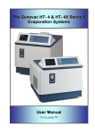
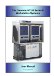
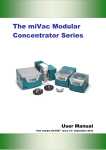
The Genevac Mega 980 &1200 Max
Evaporation Systems
User Manual
Issue 2-2 –October 2008
Part Number 04-4542
Genevac Mega 980 & 1200 Max Evaporating Systems
Contents
1
1.1
Introduction .............................................................................................................................................. 4
Amendment Control Form ....................................................................................................................... 5
Safety symbols......................................................................................................................................... 5
Genevac Evaporators and Combustible Solvents .............................................................................................. 5
2
System description and options............................................................................................................... 6
3
3.1
3.2
3.3
3.4
Scope of delivery and installation ............................................................................................................ 7
Checking the delivery............................................................................................................................... 7
Arranging commissioning ........................................................................................................................ 7
Training .................................................................................................................................................... 7
Positioning the evaporator ....................................................................................................................... 7
4
4.1
4.2
Safety ....................................................................................................................................................... 8
Safe loading of rotor................................................................................................................................. 8
Safe Lid operation.................................................................................................................................... 9
5
5.1
5.2
5.2
5.4
5.5
5.6
5.7
5.8
5.9
Getting started ....................................................................................................................................... 10
How to switch on the pump.................................................................................................................... 10
How to switch on the evaporator ........................................................................................................... 10
How to switch on the evaporator ........................................................................................................... 10
Using the keypad ................................................................................................................................... 11
What the screens do .............................................................................................................................. 12
Sample Holder Type .............................................................................................................................. 13
Sample Volume...................................................................................................................................... 13
Solvent ................................................................................................................................................... 14
SampleGuard Control Temperature ...................................................................................................... 16
SampleGuard Control Channel.............................................................................................................. 16
Coolheat Enable Pressure..................................................................................................................... 16
Chamber Temperature Control.............................................................................................................. 16
Rotor Speed........................................................................................................................................... 17
Heat-Off Option...................................................................................................................................... 17
During a run ........................................................................................................................................... 18
How to enter control data....................................................................................................................... 21
How to use SampleGuard...................................................................................................................... 26
How to use the condenser ..................................................................................................................... 28
How to start a run................................................................................................................................... 29
6
6.1
6.2
6.3
Getting the best from your system......................................................................................................... 32
Routine Checks...................................................................................................................................... 32
Problem prevention................................................................................................................................ 33
Optimising a run..................................................................................................................................... 34
7
7.1
7.2
7.3
7.4
Care of your system............................................................................................................................... 35
How to clean the chamber ..................................................................................................................... 35
Maintenance and Service ...................................................................................................................... 36
Additional equipment ............................................................................................................................. 37
Moving your system ............................................................................................................................... 38
8
Fault Finding .......................................................................................................................................... 39
9
Technical data ........................................................................................................................................ 41
Mechanical data..................................................................................................................................... 41
Condenser ............................................................................................................................................. 41
Vacuum system...................................................................................................................................... 41
Dimensions ............................................................................................................................................ 41
Operating ............................................................................................................................................... 41
Storage .................................................................................................................................................. 41
04-4542 Issue 2-2 – October 2008
Page 2 of 44
Genevac Mega 980 & 1200 Max Evaporating Systems
Contents (Continued)
10
EC Declaration of Conformity ................................................................................................................ 42
11
Safety ..................................................................................................................................................... 42
12
Warranty Statement ............................................................................................................................... 43
13
Useful information .................................................................................................................................. 44
These instructions are subject to change without notice.
No part of these instructions may be reproduced in any form or be processed, duplicated or distributed by electronic or optical means
without the written permission of Genevac Limited.
All rights reserved. © Genevac Limited
These operating instructions should be read before you use the Genevac Mega Evaporating System.
Keep them near the system for easy reference.
Your attention is drawn in particular to Section 4 Safety.
04-4542 Issue 2-2 – October 2008
Page 3 of 44
Genevac Mega 980 & 1200 Max Evaporating Systems
1
Introduction
The Genevac Series II range of evaporation systems
are state-of-the art and represent a significant step
forward in evaporation technology for the R&D
laboratory.
Drawing on extensive experience in the drug
discovery field, the Mega systems are designed to
provide very high performance coupled with ease of
use.
As you will discover, the system is simple to set up,
easy to operate and very flexible.
The status of the system is displayed and controlled
on a single keypad, display module indicating the run
time, the vacuum, rotor temperature and chamber
temperature on digital displays.
Simple to use up-down controls enable the run time,
rotor and chamber temperatures to be set in an
instant and single push buttons set the other
functions.
This manual will guide you through the start up
requirements, set up needs and operation of the
system to facilitate the most efficient procedure to
protect your product’s integrity and to ensure
optimum performance at all times.
04-4542 Issue 2-2 – October 2008
Page 4 of 44
Genevac Mega 980 & 1200 Max Evaporating Systems
Amendment Control Form
Issue
1
2-2
1.1
Reason for Change
Date Issued
Change to EU Declaration of Conformity
21 September 2004
Update U.S. address
24 October 2008
Safety symbols
The following safety symbols are used throughout this manual. The definitions and scope of each symbol is
as described below.
WARNING
THIS SYMBOL INDICATES HAZARDS THAT CAN LEAD TO SERIOUS MATERIAL
DAMAGE OR POTENTIAL SERIOUS INJURY.
Caution
This symbol provides information about hazards that can be harmful to your
health or lead to material damage.
Note
This symbol provides information about technical requirements, which if not followed,
can lead to malfunctions, inefficiency and reduced productivity.
This symbol indicates that there may be a risk to sample integrity.
Genevac Evaporators and Combustible Solvents
Please note it remains the responsibility of the user to consider safety when evaporating any combustible
solvents and ensure the system is placed in a well ventilated environment. Genevac's position regarding
evaporation of such solvents, particularly with respect to the European ATEX directive, is available on our
website or from your local sales representative.
IMPORTANT
THIS SYSTEM MUST BE
EARTHED – SEE PAGE 42
04-4542 Issue 2-2 – October 2008
Page 5 of 44
Genevac Mega 980 & 1200 Max Evaporating Systems
2
System description and options
Your Mega Evaporation System is comprised of an
evaporation chamber and rotor, combined with a
cryopump-condenser unit.
Vacuum is provided by the Scroll Pump (although
other types of vacuum pumps can be used).
Solid-state case heaters and Coolheat radiant lamps
heat the chamber and samples.
The control of chamber, bucket and sample
temperature, vacuum ramping rate, chamber
pressure, rotor speed and run time are all handled by
an embedded PC.
For the first time the end user has the facility to auto
program run parameters for any (recognised)
solvent/mixture entered.
These optimised run
parameters are highlighted in Cyan on the display
screen, when this Auto Program facility has been
selected.
Recognised Solvent(s) available from drop down
menu.
Sample Holder type available from drop down menu.
The Run Progress screen now has a fully featured
graphical display, providing annotated plots for
temperature and pressure (now a log scale).
The control software enables the user to specify and
store a library of up to 100 different evaporation
profiles in an uncomplicated manner.
Run profiles can also be linked to provide multi stage
runs. Up to 100 different profile steps can be linked
and iterative loops can also be programmed.
With a maximum single run time of just below
100 hours, the system is extremely flexible to
meet every requirement.
Scroll pump
04-4542 Issue 2-2 – October 2008
Page 6 of 44
Genevac Mega 980 & 1200 Max Evaporating Systems
3
Scope of delivery and installation
You will have purchased your system with or without
the option of commissioning by Genevac personnel.
Reference will be made in the following notes to the
installation procedures required to cover these
options.
On delivery, it is advisable to unpack your system at
the point of receipt, to ease the movement of the
component parts to the point of use.
3.1
Checking the delivery
Check the contents of the delivery as soon as
possible against the delivery note and notify
Genevac Ltd immediately of any missing or
damaged parts. (Refer to section 13 for contact
details).
3.2
Arranging commissioning
If your system is to be delivered separately, Genevac
Ltd will contact you prior to the delivery, to agree a
date to commission your system.
3.3
Training
Commissioning will normally include training in the
basic operation of the System. Further in house
training is recommended to fully exploit the flexibility
of the system.
THE EVAPORATOR MUST NOT BE OPERATED
BY PERSONNEL WHO LACK THE TRAINING OR
PROFESSIONAL
EXPERIENCE
TO
COMPREHEND THE HAZARDS THAT CAN ARISE
WHEN USING THE SYSTEM.
Personnel without such training require thorough
instruction. These operating instructions should form
the basis of this instruction.
3.4
Positioning the evaporator
POSITION THE EVAPORATOR AT LEAST 300 MM
AWAY FROM THE EDGE OF A BENCH AND THE
SAME DISTANCE CLEAR OF BREAKABLE
OBJECTS OR AREAS WHERE ENTRAPMENT
COULD OCCUR.
04-4542 Issue 2-2 – October 2008
Page 7 of 44
Genevac Mega 980 & 1200 Max Evaporating Systems
4
Safety
BEFORE OPERATING THE SYSTEM, IT IS
IMPORTANT THAT THE FOLLOWING NOTES ARE
READ TO ENSURE THAT THE IMPLICATIONS TO
THE SAFETY OF PERSONNEL OPERATING THE
SYSTEM AND FOR THE PROTECTION OF
SAMPLE INTEGRITY ARE UNDERSTOOD.
•
There are important safety
and operational
considerations to be made
when positioning the
system.
•
Refer to Section 9
Technical Data for
recommended clearances
Samples in the chamber are subjected to
accelerations of up to 450G with a maximum load
capacity of 9.6 kg per swing for a Mega 980 Max and
17.8kg for a Mega 1200 Max.
The following precautions should therefore always
be observed:
4.1 Safe loading of rotor
MEGA 980 Max
9.6kg MAX including adaptor plate
tubes, solvent, sample, sample
holder BUT excluding the swing
MEGA 1200 Max
17.8kg MAX including adaptor plate
tubes, solvent, sample, sample
holder BUT excluding the swing
For a Mega 980 Max never exceed the maximum
load capacity of 9.6kg per swing.
For a Mega 1200 Max never exceed the maximum
load capacity of 17.8kg per swing.
Balance pairs of sample holders that are loaded
opposite each other to within 10g (+/- 5g).
Note that over a maximum imbalance, as specified in
the Technical Data, the evaporator will cut out.
Locate tubes correctly in tube holders.
Locate sample blocks correctly in sample swings.
Load two or four tube holders in opposite and
balanced configurations.
Distribute tubes in sample holders symmetrically.
Rotate the rotor by hand after loading and check that
all tube holders and plates are correctly located
before starting a run and before re-starting an
interrupted run.
Always evenly distribute the tubes in
the sample holders.
Do not load tubes or vials into sample holders other
than those types that have been approved by
Genevac Ltd.
Do not use sample holders that have not been
supplied with system without consulting Genevac
Service.
Genevac Ltd will accept no
responsibility for any loss or damage
incurred by improperly or excessively
loaded rotors.
04-4542 Issue 2-2 – October 2008
Page 8 of 44
Genevac Mega 980 & 1200 Max Evaporating Systems
4.2 Safe Lid operation
The lid is opened and closed automatically by an
electric actuator.
To open the lid, select OPEN on the LID
DIRECTION switch and press both OPERATE
switches simultaneously until the lid is sufficiently or
fully opened.
BEFORE CLOSING THE LID, ALWAYS ENSURE
THAT ALL PERSONNEL AND OBJECTS LIKELY
TO BE ENTRAPPED ARE CLEAR OF THE LID
AND MATING SURFACES, PARTICULARLY IN
THE AREA OF THE HINGE.
To close the lid, select CLOSED on the LID
DIRECTION switch and press both OPERATING
switches simultaneously until the lid is fully closed.
Note that the system will not operate if the lid is
not fully closed.
4.3 Limitations of use
Your Mega Series II
unsuitable
for
use
circumstances.
04-4542 Issue 2-2 – October 2008
evaporating system is
under
the
following
•
With strong mineral acids such as HCl and HBr
at all concentrations, unless specifically built to
order.
•
For use as a pressure vessel.
Page 9 of 44
Genevac Mega 980 & 1200 Max Evaporating Systems
5
Getting started
The following notes describe the basic start up, set
up and run instructions for your Mega evaporating
system.
5.1 How to switch on the pump
Switch the pump mains switch on.
5.2 How to switch on the evaporator
Switch the mains switch on.
The screen will display the Software Control
screen.
Press the START key on the keyboard to access the
Select Run screen.
The Select Run screen will load up at the last run
that was used.
The system will not be available for use until the
vacuum pump has reached the correct operating
temperature.
5.2 How to switch on the evaporator
Switch the mains switch on.
There will be a slight delay until the condenser
reaches the correct temperature.
04-4542 Issue 2-2 – October 2008
Page 10 of 44
Genevac Mega 980 & 1200 Max Evaporating Systems
5.4 Using the keypad
The Series II keyboard controls and displays have
been designed for ease and simplicity in use.
The keyboard has the most used function keys on
the left hand side.
The right side illuminates when the RUN DATA
screen is accessed.
The START and STOP keys start and stop a
selected run.
The cursor direction keys move you around the
screen in the direction of the arrows.
The ENTER key is used to ‘open’ and ’close’ a field
on the Run Data screen when inputting or amending
data.
Note that the START key also acts as an ENTER
key when the keyboard is not illuminated.
Operating the MENU key displays the USER MENU
screen only when the rotor is not spinning and the
chamber is vented.
MENU
DISPLAY
Operating the DISPLAY key displays the RUN LOG
screen only when a run is in progress or has
finished.
Operating the SETTINGS key displays the RUN
DATA screen only for the selected run.
SETTINGS
Note that the RUN DATA screen can also be
accessed from the menu VIEW/EDIT DETAILS
option on the SELECT RUN screen when a run is
not in progress.
The following notes describe the function of each of
each screen and provides an explanation of the
prompts displayed.
04-4542 Issue 2-2 – October 2008
Page 11 of 44
Genevac Mega 980 & 1200 Max Evaporating Systems
5.5 What the screens do
There are three main control screens.
The SELECT RUN screen lists the library of
evaporation profiles you can choose.
This screen has the capacity to store 100 different
profiles, from which you can select a particular run or
set of runs.
The screen is accessed after switching on the pump
and evaporator and by pressing the START key on
the keyboard.
•
You store and select
your runs on these
screens.
•
Use the UP and
DOWN cursor keys
to move between
profiles.
By moving across the
horizontal menu bar,
•
You can START a
run.
•
You can VIEW and
EDIT a profile.
•
You can CLEAR a
profile.
•
You can COPY a
profile.
•
Start to DRAIN.
•
Start to DEFROST.
•
Start to FLUSH.
(If Option Fitted)
•
Adjust your
OPTIONS.
The 100 profiles are shown on this and nine other
screens.
The other screens can be accessed quickly by
moving the cursor down to the last entry on the page
and pressing the down cursor key.
This will take you to the last entry on the next page.
Alternatively, use the up cursor key.
04-4542 Issue 2-2 – October 2008
Page 12 of 44
Genevac Mega 980 & 1200 Max Evaporating Systems
Each line on the SELECT RUN screen is generated
from the RUN DATA screen.
When the chamber is vented and the rotor stationary,
this screen is accessed by selecting VIEW/EDIT at the
foot of the SELECT RUN screen and pressing START.
When the system is running, the RUN DATA screen
can be accessed directly by pressing the SETTINGS
key.
SETTINGS
•
Use the UP and
DOWN cursor keys
to move between
fields.
•
Press ENTER to
‘open’ a field, make
the entry and press
ENTER again to
‘close’ the field.
•
During a run, you
access this screen
by pressing the
SETTINGS key.
•
You can edit any
parameter during a
run in this way.
•
Toggle Run Data
Locked to protect
your data.
Please note that Main Menu order has changed.
It now reads:
Sample
Holder Type, Sample Volume, Solvent
Sample Holder Type
•
When selected you
are presented with
the
SAMPLE
HOLDER menu.
•
Use Cursor keys to
move up and down.
•
Press ENTER to
select.
•
Select your sample
holder type or if not
defined,
select
Other and enter
the details.
Sample Volume
•
04-4542 Issue 2-2 – October 2008
Select and
value(s).
enter
Page 13 of 44
Genevac Mega 980 & 1200 Max Evaporating Systems
Solvent
When you select this
field you are given a list
of solvent types that
have already been
programmed into the
evaporator.
Use cursor keys
move up and down.
to
Press ENTER key to
select (Highlighted in
blue).
Please note that the
solvent(s) that you have
selected from the menu
appear in the bottom
left corner of the
screen.
Select Done
finished.
when
Once your selection has been made you are now
given a new option to Auto Program the remaining
run parameters.
Press Y to accept Auto
Program.
If you have entered an
unrecognised solvent by
selecting Other from the
solvent menu, you will
not be presented with
the option to Auto
Program.
Genevac and the ATEX Directive:
Please note that it remains the responsibility of the user to consider any solvents being evaporated within the
context of the ATEX directive. The presence of solvents on the list above indicates only that they will not
damage the system. If further information is required, please contact your Sales Representative or visit
http://www.genevac.com/
04-4542 Issue 2-2 – October 2008
Page 14 of 44
Genevac Mega 980 & 1200 Max Evaporating Systems
With Auto Program
Y[es] selected.
The screen will now
display
the
Auto
Programmed data in
Cyan (Light Blue).
Save Run and continue
If you did not select
Auto Program or were
not given the option,
due to inputting an
unrecognised solvent,
then
you
will
be
presented
with
this
screen.
If editing an existing run,
parameters will remain
as previous settings.
If creating a new run,
parameters will be set to
safe default settings.
04-4542 Issue 2-2 – October 2008
Page 15 of 44
Genevac Mega 980 & 1200 Max Evaporating Systems
SampleGuard Control
Temperature
Set within the range of 20 to 70°C.
SampleGuard Control
Channel
Channel 1 in Swing or
Sample Holder.
Channel 2 in Sample.
Coolheat Enable
Pressure
Set within the range of
5–400 mbar.
.
Chamber Temperature
Control
There are now 3 options
available:
Wait for Chamber to
Heat
Range
45°C.
from
0°C
to
Wait for Chamber to
Cool
Range
45°C.
from
0°C
to
Automatic Control
Temperature
is
automatically set to an
optimised figure for the
recognised solvent /
mixture selected.
04-4542 Issue 2-2 – October 2008
Page 16 of 44
Genevac Mega 980 & 1200 Max Evaporating Systems
Rotor Speed
Low
Rotor speed applies
nominally 300 G.
High
Rotor speed applies
nominally 500 G.
Lyophilise
Not currently available
on a Mega.
Heat-Off Option
Elapsed Time
Press ENTER and input
the time after which you
want the lamps turned
off.
This can be in a range
of 0 (lamps off for the
entire run) to 99 hours
59 minutes.
Heat Flow
Not currently available
on a Mega.
Sample Detection
Monitors
the
temperature difference
between
the
2
SampleGuard channels.
04-4542 Issue 2-2 – October 2008
Page 17 of 44
Genevac Mega 980 & 1200 Max Evaporating Systems
During a run
The main section of the RUN LOG screen, gives a
graphical display of the real time changes in
chamber pressure, spin rate, sample and sample
holder temperatures.
The top left hand section, displays the current
temperatures of channels 1 and 2, the chamber
temperature, the condenser temperature, the
chamber pressure, the total time elapsed and the
stage time elapsed if linked runs are being
undertaken.
NOTE THE NEW GRAPHICAL
DISPLAY.
•
The RUN LOG screen
displays the real time
events.
•
The top left block gives
current values.
•
The top right block displays
any alarms.
•
The block at the foot of the
screen displays the current
status of the system and
Instructions.
•
Pressure is plotted on log
scale.
•
Press STOP to terminate a
run at any time.
When run enters final drying
period the display changes to
indicate the time left to End of
Run or if linked runs End of
Stage.
Press the DISPLAY key during a
run to return to the RUN LOG
screen.
Operating the STOP key at any
time during a run will terminate
the run.
The chamber will vent and the
rotor will start to spin down.
You will not be able to open the
chamber until the chamber has
reached atmospheric pressure
and the rotor has stopped
spinning.
Run finished press < > to view data.
any other key to end.
04-4542 Issue 2-2 – October 2008
When the chamber has vented
and the rotor stopped, you will be
given this STATUS prompt.
Page 18 of 44
Genevac Mega 980 & 1200 Max Evaporating Systems
When the run is finished, after pressing a key, the
following screen is displayed.
Select the DRAIN or DEFROST OPERATIONS
option using the numeric keys.
Press ENTER to display the DRAIN or DEFROST
MENU.
•
With
the
DEFROST
CYCLE highlighted, press
ENTER to start the defrost
cycle.
•
This will automatically
open the defrost valve.
•
Drain the condenser after
every run and at the end of
the day.
•
A defrosted and drained
condenser will operate
more efficiently.
•
Periodically check the
level of solvent in the
containers attached to the
drains.
Screens similar to this are
also displayed for DRAIN
and, if fitted, the FLUSH
option.
04-4542 Issue 2-2 – October 2008
Page 19 of 44
Genevac Mega 980 & 1200 Max Evaporating Systems
If you wish to end the work session on the system,
go to the Select Run screen and press STOP.
This
prompt
will
be
displayed on the SELECT
RUN screen.
Press Y to close the
system down or N to select
another run.
04-4542 Issue 2-2 – October 2008
•
The SHUT DOWN
screen will be
displayed when you
select the Y response.
•
The pump will be
purged of solvent
vapours for 30
minutes.
•
You can restart the
run by pressing
START at any point.
•
You can abort
Shutdown by pressing
START at anytime.
•
If you want to start a
different run, press
STOP, select N and
press ESC to display
the SELECT RUN
screen.
Page 20 of 44
Genevac Mega 980 & 1200 Max Evaporating Systems
•
The USER MENU is
displayed by pressing the
MENU key only when the
chamber is vented and the
rotor stationary.
•
Lamp Layer Selection is
not an option for the HT-4
or Mega.
•
In Operator Controls you
can adjust the screen
brightness to suit your
viewing angle.
•
You can turn the audible
warning off or on.
•
Press ESC to leave this
menu
Use the cursor keys to select
the OPERATOR CONTROLS
and press ENTER.
5.6
•
Use the UP and DOWN
cursor keys to adjust the
screen brightness to suit
your viewing angle.
•
Toggle the beep ON or
OFF.
•
Press ESC to exit this
screen.
How to enter control data
All control data is entered from the RUN
DATA screen.
From start up of the system and the software
control screen, press START to display the
SELECT RUN screen.
Select the VIEW/EDIT DETAILS option and
press START to display the RUN DATA
screen.
Use the UP and DOWN cursor keys to move
between fields.
Unless otherwise stated, press ENTER to
‘open’ a field, input your requirement and
press ENTER again to ‘close’ the field.
04-4542 Issue 2-2 – October 2008
Page 21 of 44
Genevac Mega 980 & 1200 Max Evaporating Systems
Run Data Locked
When set to Yes this setting protects the run data
from inadvertent corruption.
Press the ENTER key to toggle between Yes and
No.
Note that you will not be able to make amendments
or additions if the data is locked.
Lock the data after completing the run entry.
Next Run Number
This control enables you to link and loop runs in any
sequence.
If you want to link runs, list the number of the run you
want to follow the run you are entering.
Repeat this process for any subsequent runs you
would like to link.
You can also loop a run.
The limitation of how many runs you can link will be
either the maximum run time of 99 hours 59 minutes
or 99 different steps.
Linked and looped runs can always be interrupted by
manually stopping the system.
Use the DOWN cursor key to move to the next field.
Run Name
Enter the title of the run that should be no more than
20 characters long.
Use the DOWN cursor key to move to the next field.
Sample Holder Type
Press ENTER to display the Select Sample Holder
drop down menu.
Use the UP and DOWN cursor keys to select the
option and press ENTER.
If OTHER is selected, the description should be no
more than 20 characters long.
Sample Volume
Solvent
Press ENTER and input the volume in mls.
Press ENTER to display the Solvent Drop down
menu.
Use the UP and DOWN cursor keys to select the
option(s) and press ENTER.
Once your selection has been made select Done
and press Enter, you are now given a new option to
Auto Program the remaining run parameters.
If OTHER is selected, the name should be no more
than 31 characters long, press ENTER to return to
Solvent drop down menu.
04-4542 Issue 2-2 – October 2008
Page 22 of 44
Genevac Mega 980 & 1200 Max Evaporating Systems
Select Done and press ENTER.
SampleGuard Control Temperature
Press ENTER and input the temperature you wish to
limit the sample to during evaporation.
This can be in the range of 1 to +70° C.
Note that if not specified, the default setting is 30° C.
Sample Guard Control Channel
Press ENTER and input the channel on which you
want to control temperature.
Channel 1 will normally be assigned to the probe in
the sample holder and channel 2 to the probe in the
sample.
Note that when powered down, this setting defaults
to channel 1 as the control channel.
Coolheat Enable Pressure
Press ENTER and input the pressure below which
you want the lamps to be turned on.
This can be in the range of 5-400 mbar.
If nothing is selected, the setting will default to 400
mbar.
Chamber Temperature Control
Press ENTER and Select the method from the 3
options displayed:
Wait for Chamber to Heat
Range from 0°C to 45°C.
Wait for Chamber to Cool
Range from 0°C to 45°C.
Automatic Control
Temperature is automatically set to an optimised
figure for the recognised solvent / mixture selected.
Input the minimum temperature you want the
chamber to reach before spin-up will commence.
04-4542 Issue 2-2 – October 2008
Page 23 of 44
Genevac Mega 980 & 1200 Max Evaporating Systems
Rotor Speed
Press ENTER to display the Select Rotor Speed
drop down menu.
Lyophilise is not available on a Mega
Use the UP and DOWN cursor keys to select Low or
High or Lyophilise (Not available on a Mega).
Low speed applies nominally 300 G and high speed
nominally 500 G.
Selecting the Dri-Pure option described later will
over-ride this option and sets High.
If nothing is selected, the setting will default to LOW
speed.
Heat-Off Option
Heat Flow is not currently available on a Mega
Select either: Elapsed Time, Heat Flow or Sample
Detection.
For Elapsed Time enter value in hours and/or
minutes
Only requires 1 SampleGuard probe.
Heat Flow
Not currently available on a Mega
NOTE:
Control Channel Probe
MUST be placed in the swing OR SAMPLE
HOLDER
This MUST be used to control the sample holder or
swing temperature.
Either channel 1 or channel 2 may be used, ensure
that the channel chosen is selected as the control
channel in the run options.
Automatically detects dryness by monitoring the rate
at which the solvent is evaporating.
Low solvent loading or if the lamps are turned off
may cause Heat Flow to fail.
If failure occurs, select one of the other two options.
For very low solvent loading, requiring very little
heat, then the following would be used:
Sample Detection
Requires both SampleGuard probes, Channel 1 to
monitor the swing/holder temperature and Channel 2
in the centre well of the sample holder to monitor
sample temperature.
Monitors the temperature difference between the 2
channels.
At the start, they are the same, but as the samples
dry the temperature difference gets smaller.
When the temperature difference reaches the preset
figure (Not user configured), the run is terminated.
04-4542 Issue 2-2 – October 2008
Page 24 of 44
Genevac Mega 980 & 1200 Max Evaporating Systems
Heat-Off Elapsed Time
This can be in a range of 0 (lamps off for the entire
run) to 99 hours 59 minutes.
End-of-Run Option
This option is the elapsed time after which the run
will be stopped.
End-of-Run Elapsed Time
Press ENTER and input the time after which you
want the run to stop.
This can be in the range of 1 minute to 99 hours 59
minutes.
Pressure Control Regime
Press ENTER to display the Select Pressure
Control Option drop down menu.
Use the Up-Down cursor keys to select the pressure
option required.
Full Vacuum
Full Vacuum will take the chamber pressure down
to the vacuum capability of the pump.
Controlled Pressure
When the Controlled Pressure option is selected,
the Controlled Pressure field will be displayed.
Move down to this field using the DOWN cursor key
and press ENTER.
Input the pressure you want the chamber to be
limited to in the range of 0 to 500 mbar.
Dri-Pure
DRI-PURE
reduces
the
vacuum
over
a
predetermined period to 50 mbar, then goes to the
control pressure as set by the user.
This feature is particularly useful in preventing
bumping, (the violent boiling of solvents), resulting in
solvents being expelled, which is a source of cross
contamination of samples.
Bumping can also cause products to be deposited on
the glass lenses of the Coolheat lamps, which
eventually results in breakages.
Note that during the DRI-PURE cycle, which is
approximately 40 minutes, the Coolheat function will
be disabled.
Variable Dri-Pure
Variable Dri-Pure allows the user the option to set:
1) The pressure at which the vacuum ramp will
start.
2) The pressure at which the vacuum ramp will end.
3) The total duration of the vacuum ramp.
4) Final Controlled Pressure.
04-4542 Issue 2-2 – October 2008
Page 25 of 44
Genevac Mega 980 & 1200 Max Evaporating Systems
5.7
How to use SampleGuard
SampleGuard is a dual channel temperature
controller that operates when the rotor is spinning.
Thermocouple type probes are connected to the
SampleGuard housing as shown.
One probe is used to control the sample holder
temperature and the other the sample temperature.
The SampleGuard housing is stamped next to the
connectors to identify channels 1 and 2.
The third connection is for a remote power supply to
power SampleGuard to verify temperature calibration
(refer to later notes).
Always ensure that channel 1 is used to monitor and
control the sample holder temperature and channel 2
to control the sample temperature.
Always use channel 1 as the control channel as
using channel 2 under these circumstances, could
result in damage to thermo labile samples.
Depending on the solvents being evaporated and the
conditions, significant cooling and/or freezing will
normally occur.
Under these conditions using microtitre plates, it is
advisable to position the sample probe in a sample
well near the centre of the plate.
Since the central wells are surrounded by other
frozen or cold wells, there will be a significant
thermal drain.
Under these conditions, dryness may well occur in
the outer wells whist the central samples remain in
solution or frozen.
When positioning the sample probe, always ensure
that the probe tip is located firmly at the bottom of
the well, vial or tube.
The use of Genevac Heat Transfer Plates would prove to be beneficial in preventing this
condition arising, by providing an even heat transfer to your samples.
Please refer to our “Options & Accessories Brochure” to get the best solution for needs.
Available in pdf format, as a download, from our web site:
http://www.genevac.co.uk/
04-4542 Issue 2-2 – October 2008
Page 26 of 44
Genevac Mega 980 & 1200 Max Evaporating Systems
Note that the term TxD indicates that the transmitter
is not transmitting and will be displayed when the
rotor is not rotating.
The control temperature can be changed during a
run by pressing the SETTINGS key to display the
Run Data screen.
Use the cursor keys to select the SampleGuard
Control Temperature field and press ENTER.
Input the new value and press ENTER again.
The system will prompt you to confirm the change
when you leave the Run Data screen.
Press Y for yes and N for no.
To verify the calibration of SampleGuard, remove the
Stuffer Plug shown, connect the remote power lead
and connect probes to channels 1 and 2.
With the lid open, immerse both probes in a beaker
of water at approximately 40 degrees Centigrade.
Press the START key and verify the indicated
temperatures
against
a
calibrated
digital
thermometer.
The frequency of verification and record retention,
should meet the requirements of your ISO/EN/BS
9000 series or NAMAS procedures.
On removal of the remote power lead, always ensure
that the Stuffer Plug is replaced.
SampleGuard will not operate without the Stuffer
Plug.
04-4542 Issue 2-2 – October 2008
Page 27 of 44
Genevac Mega 980 & 1200 Max Evaporating Systems
5.8
How to use the condenser
ENSURE THAT A SUITABLE RECEPTACLE IS
CONNECTED TO THE DRAIN, PRIOR TO SWITCH
ON, AS DRAINING OCCURS AUTOMATICALLY.
The automatic condenser (VC8000TA) is designed
to ensure maintenance free and optimised
condensing and that a fresh cryopump is always
available.
The condenser starts in automatic mode when
powered up (switched ON). This is indicated by the
AUTOMATIC LED being illuminated.
When initially powered up CONDENSER 1 starts its
chilling cycle, indicated by a rapid drop in
temperature on the display.
The cryopump pots automatically switchover during
the run. The temperature indicators and HOLDING
switch lamps reflect this.
Provision has been made to manually over-ride the
automatic process.
After switchover the operator is able to hold the
condenser on the current pot. This could be used to
prevent switchover if the end of the run is imminent.
When the HOLDING button is pressed the
AUTOMATIC LED will extinguish, the HOLDING
LED and the AUTOMATIC switch will illuminate.
When flushing the condenser
To re-enter automatic mode press the AUTOMATIC
button, the AUTOMATIC button and the HOLDING
LED will extinguish and the AUTOMATIC LED will
illuminate. At which point the drain and switchover
cycle takes place.
Start venting the chamber prior to
carrying out the flush.
This prevents flushing the whole
chamber, which is undesirable.
04-4542 Issue 2-2 – October 2008
Page 28 of 44
Genevac Mega 980 & 1200 Max Evaporating Systems
5.9
How to start a run
This section will describe a typical evaporation run of
DMSO.
In this example, two sets of eight 28 x 60 mm
scintillation vials each containing 5 ml of DMSO were
held in solid aluminium sample holders.
SampleGuard control temperature was set at 40
degrees centigrade and the pressure to full vacuum.
To prevent condensation, the chamber
preheated to 40 degrees centigrade.
was
Switch on the pump, evaporator and condenser.
Display the Run Data screen and input the following
data.
Run Data Locked .................................................................... No
Next Run Number ......................................................................0
Run Name ...........................................DMSO 28 x 60 mm tubes
Sample Holder Type .......................... Solid Aluminium 28 x 60
Sample Volume ..........................................................................5
Solvent............................................................................... DMSO
SampleGuard Control Temperature.......................................40
SampleGuard Control Channel ................................................1
Coolheat Enable Pressure ....................................................100
Chamber Temperature Control ..............................................40
Rotor Speed ..........................................................................Low
Heat Off Elapsed Time .......................................................01:40
End of Run Elapsed Time ..................................................01:40
Controlled Pressure ..................................................................0
04-4542 Issue 2-2 – October 2008
Page 29 of 44
Genevac Mega 980 & 1200 Max Evaporating Systems
Dispense the DMSO into the vials and load the
sample holders into the sample swings.
Always use the upper level when loading partial rotor
loads.
Always ensure that the vials, sample holders and
sample swings are correctly and securely located.
Position the SampleGuard probe in its’ location hole
in the sample holder and connect to channel 1 on the
rotor.
Position the sample SampleGuard probe in a central
vial and connect it to channel 2 on the rotor.
Always ensure that the tip of the sample probe is
located at the bottom of the vial.
Switch the lid selector to close and close the lid of
the evaporator ensuring that no items will be
entrapped by the lid.
Press the START key.
The system will indicate that the chamber is warming
up.
This will take approximately twenty minutes.
When the chamber is up to temperature, the system
will start automatically.
With aluminium sample holders of this thermal
capacity, some time can be gained by preheating
them in an oven to 40° C.
04-4542 Issue 2-2 – October 2008
Page 30 of 44
Genevac Mega 980 & 1200 Max Evaporating Systems
A brief discussion is given here to give the user a
better understanding of the processes involved.
When the run is started, the pressure will drop
steadily as air is evacuated from the chamber and
condenser.
Notes on probe position and channel choice
•
Use channel 1 to control the sample holder or
rotor temperature, as this will always ensure that
the sample temperature will never exceed the
control temperature you set.
•
Outer tubes or wells in microtitre plates
invariably dry more quickly than central ones.
This is because the central positions are
surrounded by ‘cold’ neighbours.
•
Choose central positions to be sure that all
locations are ‘dry’ or an outer position if you are
unsure of how long a particular run will take.
•
•
•
•
The upper rotor has two diametrically situated
holes for probes. Alternatively, use one of the
holes in the sample holder as shown.
Always use the same channel as the control
channel, as once this is changed for a particular
program, it will remain so.
If you do change the control channel for a
particular run, this may cause confusion between
different users and could give rise to product
damage.
Periodically inspect the
connections for damage.
probe
ends
and
With the Coolheat lamps operating from 100 mbar
and because the chamber has been pre-heated to
40° C, the sample holders soon reach the pre-set
temperature.
The maintenance of the 40° C ceiling clearly shows
the benefit of having and using SampleGuard.
As solvent starts to evaporate, the pressure drop will
stop or reduce in rate.
The temperature of the sample drops due to
evaporative cooling.
Provided there is sufficient vacuum, the drop in
sample temperature will take place even though the
Coolheat lamps are on.
This will substantially reduce the evaporation rate
and the pressure and vapour flow will drop until a
steady state is reached.
There is then normally a long period of constant
pressure and vapour flow whilst the bulk of the
solvent is evaporated.
As the solvent approaches dryness, the evaporation
rate often reduces, causing the vapour pressure to
drop.
This is particularly noticeable with ‘oily’ samples
whose vapour pressure is very low.
At this point, the sample temperature will start to rise
and reach the SampleGuard control temperature in a
reasonably short time.
A few minutes after, the sample temperature reaches
the control temperature, stop the system and inspect
the samples.
Other evaporation run profiles are given in section
6.3 Optimising a run.
04-4542 Issue 2-2 – October 2008
Page 31 of 44
Genevac Mega 980 & 1200 Max Evaporating Systems
6
Getting the best from your system
6.1
Routine Checks
For high boiling point solvents such as DMSO, NMP,
DMF and DMI the best evaporation rates will only be
achieved at pressures better than 0.5 mbar.
Check all clamped joints on a regular basis to ensure
that they are secure.
Always ensure that the condenser pots are drained
before every run.
Flush the condenser pots with a suitable solvent at
regular intervals.
Check the catch pot connected to the pump exhaust
on a regular basis and drain as necessary
Never pump a heated condenser containing traces of
liquid DMF, DMSO or NMP, as this will contaminate
the pump oil.
Check the pump oil level initially on a daily basis until
a usage pattern has been established and then once
weekly (CVP Only).
Ensure that the oil level is within the notch on the
dipstick and no lower than the middle of the notch
(CVP Only).
Keep a weekly log of the time taken for your system
to reach full vacuum, as this data will give you an
indication of seal ageing and wear.
With high boiling point solvents, it is advantageous to
pre-heat aluminium sample holders before
commencing a run to increase evaporation speed.
Use the link run facility when evaporating solvent
mixtures with large differences in boiling point (refer
to 6.3 Optimising a run).
04-4542 Issue 2-2 – October 2008
Page 32 of 44
Genevac Mega 980 & 1200 Max Evaporating Systems
6.2
Condensation
Problem prevention
Condensation of the evaporating solvent will occur
when the solvent vapour temperature is above that
of the chamber walls.
This is most likely to occur with commonly used
solvents such as NMP, DMI, DMSO and possibly
DMF.
To prevent this, it will be necessary to pre-heat the
chamber.
To do this, remove the sample holders and set the
Minimum Chamber Temperature field to 40 degrees
on the Run Data screen and start the run.
The chamber will take approximately 20 minutes to
reach this temperature.
Note that the Coolheat lamps will not operate during
this pre-heating cycle.
If condensation occurs unexpectedly, immediately
switch off the lamps by entering 0 into the Heat of
Elapsed Time field on the Run Data screen.
Pre-heating the chamber is not recommended when
evaporating volatile solvents such as TFA,
acetonitrile or methanol.
TFA Creep
TFA exhibits the property of ‘creeping’ which, is the
movement of the TFA in liquid phase up the inside of
the tubes, vials or microtitre plates.
Problems can arise if solvent containing product is
deposited in this way on the top face of plates.
During rotation of the rotor, solvent and product are
thrown onto the Quartz glass windows in front of the
lamps.
Whilst the solvent evaporates, the product becomes
carbonised by the heat from the lamps and form
sites for crack propagation to take place.
Inspect glasses at regular intervals and clean with a
lint free cloth and acetone.
If the contamination becomes excessive and
carbonised as shown, contact Genevac Service.
Genevac manufacture a range of specialised sample
holders to protect the Quartz lenses. Call Genevac
Sales for details.
Bumping and spitting is unpredictable and may occur
with any solvent or mixture.
04-4542 Issue 2-2 – October 2008
Page 33 of 44
Genevac Mega 980 & 1200 Max Evaporating Systems
Limiting the chamber pressure
•
Bumping must be avoided, as it is a potential
source of cross contamination between samples.
•
Bumping can also cause product to be deposited
on the glass lenses as previously described
Use the Dri-Pure option on the drop down menu
under Pressure Control Regime on the Run Edit
screen.
This option incrementally reduces the pressure and
automatically sets the rotor speed to high.
6.3
Optimising a run
This section will describe some of the general
principles applicable to optimising evaporation rates
by exploiting the flexibility of the Series II control
software.
Pressure control can be used to significantly
increase the evaporation rate of mixtures of greater
than 30% water when contained in glass tubes and
beakers.
When evaporating aqueous mixtures at pressures of
less than 4 mbar, ice can form and extend the
evaporation time.
At a pressure of 6 mbar, ice crystals are not formed
and the time required for evaporation can be
reduced by up to 30%.
Mixtures of water and methanol in deep well
microtitre plates however, respond entirely differently
as shown by the graphs shown on the next page.
At full vacuum, a reasonable evaporation rate is
achieved whilst at 8 mbar; the time required for
evaporation is increased significantly.
Linking Runs
When evaporating 40 ml fractions in 24 x 150 mm
glass tubes or larger volumes in beakers, typical
evaporation times for water - acetonitrile mixtures
can be in excess of 8 hours.
A reduction can be achieved by setting the
SampleGuard control temperature to 60 degrees
centigrade for a defined period.
Provided the period was not excessive, the sample
temperature is likely to remain below 40°C, even
though the Coolheat lamps remain on as result of
evaporative cooling.
After this period, a second or a number of
successive runs can be linked at reduced
SampleGuard temperatures and different pressures.
Some experimentation would be necessary to
ensure that safe sample temperatures are not
exceeded.
04-4542 Issue 2-2 – October 2008
Page 34 of 44
Genevac Mega 980 & 1200 Max Evaporating Systems
7
Care of your system
The routine checks and the day to day care points
you should be aware of, were detailed in section 6.1
Routine checks.
The remainder of this section will address the less
frequent system checks.
7.1
How to clean the chamber
As mentioned in section 6.2 Problem Prevention,
TFA creep can give rise to debris being deposited on
the inside of the chamber and on the Quartz glasses.
Periodic inspection of the glasses, the inside of the
chamber and rotor is recommended to avoid an
unacceptable build up of potential contaminants.
Excessive build up of debris on the pivoting
faces of the sample swings and rotors, can give
rise to sample swings sticking in the out position
and result in product loss.
Inspect the sample swings on a weekly basis for free
movement and the inside of the chamber and
glasses for build up of debris.
Clean with acetone taking care to avoid contact
with the outside paintwork and accessories of
the chamber.
Use the accepted Health and Safety precautions in
using acetone in this manner.
04-4542 Issue 2-2 – October 2008
Page 35 of 44
Genevac Mega 980 & 1200 Max Evaporating Systems
7.2
•
Seals and bearings will wear with use.
•
Over a period of time, this will result in a
gradual decline in performance of your
system.
•
Lack of any maintenance at all, will result in
unscheduled breakdowns and costly down
time.
•
Planned
preventative
service
and
maintenance, will keep your system
operating at peak performance.
•
Please refer to section 12
Information for contact details.
•
Keep a weekly log of the time taken for
your system to reach full vacuum and the
full vacuum achieved.
•
Useful
This data will give an indication of the
performance of your system.
Maintenance and Service
Every effort has been made during the design and
manufacture of your system to assure the build
quality and reliability of your system.
Over a period of time however, there will be some
degree of wear and ageing of the seals and bearings
in the chamber, condenser and pump.
The extent of wear and ageing will depend on the
utilisation of the system, the severity of temperature
cycling and the nature of the solvents being used.
With some solvents, pin hole corrosion may occur in
the connecting tubes which will result in a decline in
performance.
Drops in performance are manifested in the time
taken to reach full vacuum, the level of full vacuum
and a general decline in evaporating efficiency.
In order to keep your system at peak performance
and to avoid costly and unscheduled down time, we
strongly recommend some form of planned
maintenance.
Because of the complexity of changing parts in the
field, a high level of skill is required to maintain a
complete system.
To this end, Genevac can offer a range of
preventative maintenance, service and breakdown
contracts to cater for your particular needs.
04-4542 Issue 2-2 – October 2008
Page 36 of 44
Genevac Mega 980 & 1200 Max Evaporating Systems
7.3
Additional equipment
There may be future applications for which your current range of sample holders are not adequate.
The following accessories are just an example of the many ways in which Genevac can assist you in
developing your system for the future.
For further information or to discuss any ideas you may have, please call Genevac Sales.
•
•
•
All sample holders are of a solid aluminium construction and black anodised to improve heat
absorption
Maximum contact area provide good physical support, optimum heat transfer and even heat
distribution
Solid aluminium tube holders provide even heat distribution for uneven drying loads
FastStack for shallow well plates
Side Bridge
Medium length tube holder
Short tube holder
FastStack for deep well plates
Flask holder
04-4542 Issue 2-2 – October 2008
Page 37 of 44
Genevac Mega 980 & 1200 Max Evaporating Systems
7.4
Moving your system
These notes are included to assist you in moving
your system to another area.
Before moving your system, the following key points
should be addressed.
•
•
•
•
•
•
•
•
Ensure that there is sufficient floor space to
position your system.
Ensure that there is an adequate power supply.
Ensure that there is adequate ventilation.
Ensure that there is sufficient clearance for
adequate ventilation of the pump and condenser.
Ensure that provision has been made for the
drainage of condenser solvents and the pump
exhaust.
Ensure that the condenser pots are drained and
flushed.
Ensure that the sample swings are removed
form the rotor.
Ensure that all the clamps, seals, tubes, cables
and these instructions are retained together.
The system is provided with wheels for easy
movement for access and service.
It is also provided with feet which should normally be
screwed down to prevent excessive movement
during operation.
If the load is 300g or more out of balance, the
vibration sensor will close the system down
automatically.
If the feet are not screwed down, this can occur with
considerably lower out of balance loads.
Feet shown in the retracted position
04-4542 Issue 2-2 – October 2008
Page 38 of 44
Genevac Mega 980 & 1200 Max Evaporating Systems
8
Fault Finding
This section will describe potential errors and faults
that may occur and lists their probable causes.
The symptoms are listed on the left hand side of the
page and the source of solutions on the right.
Always check that you have called up the correct
run from the Select Run screen.
Probable cause
Temperature
•
The sample temperature exceeds the control
limit.
•
The wrong control channel has been selected or
the probes have been connected to the wrong
channel (refer to section 5.7 How to use
SampleGuard).
•
The Coolheat lamps will not switch on.
•
The Coolheat enable pressure has been set
incorrectly (refer to section 5.6 Coolheat Enable
Pressure).
The lamps have not been enabled (refer to
section 5.5 Lamp Layer Menu).
The heat off elapsed time has not been specified
or specified incorrectly (refer to section 5.6 Heat
Off Elapsed Time).
•
•
Probable cause
Pressure
•
The system will not reach full vacuum.
•
•
•
General
•
The system did not stop when I expected it to.
The chamber pressure may be controlled (refer
to section 5.6 Controlled Pressure).
Dri-Pure may have been selected (refer to
section 5.6 Dri-Pure).
There may be a leak in the system (refer to
Leaks below).
Probable cause
•
•
You may have inadvertently linked a run (refer to
section 5.6 Next Run Number).
You may have inadvertently looped a run (refer
to section 5.6 Next Run Number).
•
The run is taking far longer than I expected.
•
Check that the condenser pot in use has been
drained (refer to section 5.8 How to use the
condenser).
•
The system has shut down and I have an
imbalance alarm prompt.
•
Check the sample holders and contents for
weight differences of greater than 50g (refer to
section 4.1 Safe loading).
04-4542 Issue 2-2 – October 2008
Page 39 of 44
Genevac Mega 980 & 1200 Max Evaporating Systems
Specific
• Suspected leak - pressure of no better than 5
mbar.
(Be sure to check that you have NOT limited the
pressure setting. Check the pressure setting
regime before proceeding any further).
Probable cause
•
•
•
•
•
•
•
•
•
Check the security of all the clamps on the
system. If these are obviously tight and in good
condition, apply the following procedure.
Use a process of elimination to isolate the leak
(you will need a separate vacuum gauge with a
resolution of better than 0.5 mbar - contact
Genevac for details).
Disconnect the pump from the connecting tube
and connect the vacuum gauge transducer
directly to the vacuum port.
Start the pump and note the pressure after three
quarters of an hour. This should be better than
1mbar. If not, contact Genevac Service for
advice.
If the pump is satisfactory, reconnect the
connecting tube from the condenser and
disconnect the tube at the condenser end.
Connect the vacuum transducer directly to the
end of the tube and switch the pump on.
If the pressure is no better than 1 mbar, replace
the tube.
If the tube is satisfactory, reconnect the tube to
the condenser and restart the system.
If the same conditions prevail, contact Genevac
Service for assistance.
Condenser
• Condenser not getting to temperature (- 40° C).
Probable cause
•
Contact Genevac Service for assistance.
Electrical
• No power to any part of the system.
Probable cause
•
Check the circuit breaker on the mains supply to
the system and reset if necessary.
•
Check switches.
•
If the fault persists, contact Genevac Service for
assistance.
• No power to the pump and condenser.
•
As above
• No power to the chamber.
•
As above
• Lid will not open - system powered up.
•
Contact Genevac Service for assistance.
04-4542 Issue 2-2 – October 2008
Page 40 of 44
Genevac Mega 980 & 1200 Max Evaporating Systems
9
Technical data
Mega 980 Max
Mega 1200 Max
900 (Low Speed)
1100 (High Speed)
1100 Dri-Pure
300-450G
Direct
200g
Refer to Page 8
12
1000 kg
810 (Low Speed)
990 (High Speed)
990 Dri-Pure
300-450G
Direct
250g
Refer to Page 8
24
1300 kg
-45°C
+60°C
2 x 8.0 litres
2.5 litres
No
Yes
316 Stainless steel
Stainless steel/PTFE
-45°C
+60°C
2 x 8.0 litres
2.5 litres
No
Yes
316 Stainless steel
Stainless steel/PTFE
0 -1000 mbar
0 -1000 mbar
Yes
Yes
0.4 mbar
0 -1000 mbar
0 -1000 mbar
Yes
Yes
0.4 mbar
1382 x 1084 x 1371 mm
1382 x 1084 x 2313 mm
1600 x 1304 x 1371 mm
1600 x 1304 x 2521 mm
Mechanical data
Max rotor speed
Max Force
Drive system
Operation imbalance
Max load
IR lamps number
Weight
Condenser
Condenser temperature
Minimum
Maximum
Vacuum condenser capacity
Exhaust condenser capacity
Condenser level detector
Rapid defrost
Condenser chamber
Condenser drain valve
Vacuum system
Pressure display/resolution
Vacuum control
Dri-Pure
Auto vacuum vent valve
Ultimate system vacuum
Dimensions
Evaporator (W x D x H)
Lid Closed
Lid Open
Electrical
Power supply
230V, 50Hz, single phase, 25A, 5.8kW
208V, 60 Hz, single phase, 25A, 5.8kW
Environment
The following figures apply:
Operating
Ambient Temperature:
Relative Humidity:
Altitude:
15°C to 30°C
10 – 60%
Sea Level to 1,600m
Storage
Ambient Temperature:
Relative Humidity:
Altitude:
04-4542 Issue 2-2 – October 2008
-10°C to 60°C
10 – 80%
Sea Level to 12,000m
Page 41 of 44
Genevac Mega 980 & 1200 Max Evaporating Systems
10 EC Declaration of Conformity
11 Safety
We Genevac Limited
Declare that this product:
Mega Series II Evaporating System
Complies with the relevant Essential Health and
Safety Requirements of the European Machinery
Directive (89/392/EEC as amended by 91/368 EEC
and 93/44/EEC). The EMC Directive 89/336/EEC
and the Low voltage Directive 73/23/EEC.
Conformity is demonstrated by compliance with the
following Harmonised European Standards:EN 60204-1:1998, Safety of machinery– Electrical
equipment of machines-Pt 1 General Requirements
EN 294: 1992, Safety of machinery– Safety
distances to prevent danger zones being reached by
upper limbs.
EN 1088: 1996, Safety of machinery. Interlocking
devices associated with guards. Principles of design
and selection.
BS EN ISO 12100 pts 1 & 2:2003, Safety of
Machinery - Basic concepts, general principles for
design.
WARNING!
THIS SYSTEM MUST BE EARTHED
THIS EVAPORATOR IS A SAFETY CLASS 1
PRODUCT
ACCORDING
TO
IEC
CLASSIFICATION. IT MUST NEVER BE USED
WITH ANY INTERRUPTION TO THE SAFETY
EARTH CONDUCTOR. IT IS AN INSTALLATION
CATEGORY II PRODUCT AND IS INTENDED TO
OPERATE FROM A NORMAL SINGLE-PHASE
SUPPLY.
THIS EVAPORATOR HAS BEEN DESIGNED TO
BE USED IN A POLLUTION DEGREE 1
ENVIRONMENT (NO POLLUTION, OR ONLY DRY
NON-CONDUCTIVE POLLUTION).
ANY MAINTENANCE OR REPAIR OF THIS
PRODUCT SHALL BE CARRIED OUT BY
GENEVAC
PERSONNEL
(OR
APPROVED
REPRESENTATIVES OF GENEVAC) USING ONLY
APPROVED SPARE PARTS
BS EN 50082-1: 1998, Electromagnetic compatibility
– Generic immunity standard.
BS EN 61010-2-020: 1995, Safety requirements for
electrical equipment for measurement, control and
laboratory use. Particular requirements for laboratory
centrifuges.
04-4542 Issue 2-2 – October 2008
Page 42 of 44
Genevac Mega 980 & 1200 Max Evaporating Systems
12 Warranty Statement
This product is guaranteed for period of 12 months from the date of delivery to site. In the unlikely event of any
defect arising due to faulty materials or construction resulting in system failure, the unit will be repaired free of
charge. This to include all labour and component costs incurred.
This warranty is subject to the following provisions:
1. System must be sited, installed and operated in accordance with operator instruction manual.
2. Unit only used for purpose it was sold, and in accordance with Genevac published compatible solvent
list.
3. Regular cleaning and preventative maintenance schedule to be adhered to as detailed in operator’s
manual.
4. Warranty does not cover accidental damage, misuse, modifications or inappropriate repair by untrained
personnel.
5. Warranty does not cover consumable items*
Failure to adhere to the above would result in the costs of repairs being charged.
* Consumable Items:
Sample Guard thermocouple probes
Control fuses
04-4542 Issue 2-2 – October 2008
Page 43 of 44
Genevac Mega 980 & 1200 Max Evaporating Systems
13 Useful information
Genevac Limited
The Sovereign Centre
Farthing Road
Ipswich
IP1 5AP
United Kingdom
Sales and Service Hotlines
Service Hotline: +44 (0) 1473 243000
If you need to contact Genevac for assistance, use
either the telephone or fax Hotlines given.
It will always help Genevac Service if you have the
serial numbers at hand for the components of your
system
If you need to contact Genevac Sales for information
on Service Contracts or products, use the telephone
or fax Hotlines given.
Alternatively, Email or visit our web site.
Sales Hotline: +44 (0) 1473 240000
Fax: +44 (0) 1473 461176
Email: [email protected]
Web site: http://www.genevac.com
Genevac Inc
SP Industries
815 State Route 208
Gardiner
NY 12535
United States of America
Sales and Service Hotline
(1) 845 267 2212
Fax (1) 845 267 2212
Email: [email protected]
04-4542 Issue 2-2 – October 2008
Page 44 of 44