1
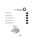
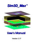
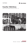
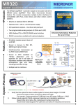
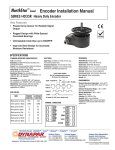
Drive Application Software
Application Set
Application Set Title
Drive Product
File Name for (AS)
Date / Revision
Position Profile – Encoder Incremental
PowerFlex® 700 Vector Control (Series B)
AS PF700 Position Profile Encoder Incremental.doc
8/11/05
-
01
Attention:
This document and related file(s) are designed to
supplement configuration of the listed drive product. The
information provided does not replace the drive products
user manual and is intended for qualified personnel only.
Description:
The Position Profile is used to move incrementally to the desired position. The position is
determined by the step being used as the starting step. For this example, two selector switches
(Pos Sel 1 & Pos Sel 2) are used to choose step 1, 2 or 3 as the starting position.
Limitations:
If both selector switches (Pos Sel 1 & 2) are off (false) when a start command is issued, the
profile will not operate because this is an invalid state. To recover from this the drive must be
stopped and profiling must be disabled via P88 or power must be cycled.
Options &
Notes:
The starting step of the indexer can be controlled via digital inputs or by manipulation of the
Pos/Spd Prof Cmd word. This example uses digital inputs.
After downloading *.dno file, the Motor Data and Motor Tests portions of the Basic Startup
should be performed through the LCD HIM. Then tune the Speed Regulator Bandwidth and
Position Regulator Filter and Gain for desired performance.
Drive Input & Output Connections:
Inputs
Function
DI 1
4 – Stop CF
DI 2
5 - Start
DI 3
0 - Not Used
DI 4
52 – Pos Sel 1
DI 5
53 – Pos Sel 2
DI 6
0 – Not Used
AI 1
AI 2
Outputs
DO 1
DO 2
DO 3
AO 1
AO 2
Description
P361
P362
P363
P364
P365
P366
Not Used
Not Used
Function
Description
Not Used
Not Used
Not Used
Not Used
Not Used
AS_PF700_Position_Profile_Encoder_Incremental.doc
Form Revision – A
Page 1 of 5
Drive Application Software
Application Set
Parameter Configurations
Changes from Default Parameter Settings (Any listed defaults are in gray.)
Par
Name
Value
Link
Description
41Motor NP . . .
per nameplate
(Data entered per motor nameplate)
45
4 - “FVC
53
Motor Cntl Sel
Vector”
80
Feedback Select
3 - “Encoder”
Must use quadrature and differential encoder
7 – “Pos/Spd
88
Speed/Torque Mod
Enables position/speed profiling.
Prof”
This must be set high enough (negative) to not limit
153
Regen Power Lim
-200.0
deceleration into position otherwise overshoot will
occur.
All regenerative energy dissipated into braking
161
Bus Reg Mode A
Dynamic Brak
resistor.
An External resistor may be required for high duty
163
DB Resistor Type
Internal Res
cycle or low friction applications. Sizing of resistor is
determined by the loads and speeds of application.
190
Direction Mode
1 – “Bipolar”
Allows position loop to control direction.
Disables alarm condition to defeat requirement to run
259
Alarm Config 1
Bit 17 = 0
a homing routine. The User must determine if this is
necessary for the application.
Typical range will be 20-40 rad/sec. Adjusting this will
449
Speed Desired BW
40 Rad/Sec.
automatically change Parameters 445 and 446
For Reference Only. Automatically adjusted when
445
Ki Speed Loop
(475.8)
Parameters 449 is changed.
For Reference Only. Automatically adjusted when
446
Kp Speed Loop
(47.6)
Parameters 449 is changed.
For Reference Only. Automatically determined during
450
Total Inertia
(1.19 Sec)
inertia autotune. (Note: Kp = BW x Inertia)
***
Position Indexer
Bit 0 =
Bits 0 – 4 Control what step the profile will start at.
Bit 1 =
The digital inputs are used in this setup as noted on
Bit 2 =
Bit 3 =
page 1. (binary value determines step number)
Bit 4 =
705
Pos/Spd Prof Cmd
Bit 5-7 = na
Bits 8 Hold Step, not used
Bit 8 = 0
Bit 9 Redefine Pos, not used
Bit 9 = 0
Bit 10 = 0
Bit 10 Find Home, not used
Bit 11 Vel Override, not used
Bit 11 = 0
Bit 12-15 = na
707
Encoder Pos Tol
10
Defines the tolerance window of “at position”.
This defines the number of encoder pulses equal to 1
unit. It can be scaled to a rotational or linear motion as
708
Counts per Unit
4096
desired by the User.
(4096 = 1 rev of 1024PPR quadrature encoder)
Default is 1/10 of maximum speed. Set to the lowest
713
Find Home Speed
10% of max
possible value to reduce overshoot.
This value will typically be less than the default value
714
Find Home Ramp
10.0
of 10 seconds.
AS_PF700_Position_Profile_Encoder_Incremental.doc
Form Revision – A
Page 2 of 5
Drive Application Software
Application Set
718
Pos Reg Filter
75
719
Pos Reg Gain
12
***
720
721
722
723
724
Step Data
Step 1 Type
Step 1 Velocity
Step 1 AccelTime
Step 1 DecelTime
Step 1 Value
4
500.0
1.00
1.00
10.00
725
Step 1 Dwell
1.00
726
727
730
731
732
733
734
Step 1 Batch
Step 1 Next
Step 2 Type
Step 2 Velocity
Step 2 AccelTime
Step 2 DecelTime
Step 2 Value
735
Step 2 Dwell
736
737
740
741
742
743
744
Step 2 Batch
Step 2 Next
Step 3 Type
Step 3 Velocity
Step 3 AccelTime
Step 3 DecelTime
Step 3 Value
745
Step 3 Dwell
1.00
746
747
870
871
872
873
874
875
876
877
Step 3 Batch
Step 3 Next
Step 16 Type
Step 16 Velocity
Step 16 AccelTime
Step 16 DecelTime
Step 16 Value
Step 16 Dwell
Step 16 Batch
Step 16 Next
1
16
7
0.00
1.00
1.00
n/a
0.50
1
16
1
16
4
1000.0
1.00
1.00
15.00
1.00
1
16
4
1500.0
1.00
1.00
20.00
This is a low pass filter whose value should be 5-6
times the gain value set in P719.
This gain adjusts the responsiveness of the position
regulator. Increase the value for better response.
Selects an encoder incremental move.
Speed and direction for step 1
Acceleration time for step 1
Deceleration time for step 1
Number of units to travel for step 1
Seconds to hold at position when step value is
reached.
Number of times to do this step consecutively.
The step to go to after this step is complete.
Selects an encoder incremental move.
Speed and direction for step 2
Acceleration time for step 2
Deceleration time for step 2
Number of units to travel for step 2
Seconds to hold at position when step value is
reached.
Number of times to do this step consecutively.
The step to go to after this step is complete.
Selects an encoder incremental move.
Speed and direction for step 3
Acceleration time for step 3
Deceleration time for step 3
Number of units to travel for step 3
Seconds to hold at position when step value is
reached.
Number of times to do this step consecutively.
The step to go to after this step is complete.
Selects “End and Hold Position”
Speed and direction for step 16
Acceleration time for step 16
Deceleration time for step 16
Number of units to travel for step 16
Seconds to hold at position.
Number of times to do this step consecutively.
The step to go to after this step is complete.
Tuning Tips:
1. After downloading the *.dno file, the Motor Data and Motor Tests portions of the Basic Startup should be
performed through the LCD HIM.
2. Speed Regulator Settings
P449 [Speed Desired BW] should be set to a point below where instability occurs.
3. Position Regulator Settings
P719 [Pos Reg Gain] should be increased to a value that is just below the point where overshoot occurs.
P718 [Pos Reg Filter] must be adjusted at a rate that is 5-6 times the value of P719.
AS_PF700_Position_Profile_Encoder_Incremental.doc
Form Revision – A
Page 3 of 5
Drive Application Software
Application Set
The plot below shows how the profile will operate when a different starting step is used. The sequence was as
follows:
1. Pos Sel 1 = on, Pos Sel 2 = off. A start command issued. Step 1 moves incrementally 10 units. Once at
position, a one second dwell at position occurs. The step completes and jumps to step 16 which is programmed to
end the profile.
2. Pos Sel 1 = off, Pos Sel 2 = on. A start command issued. Step 2 moves incrementally 15 units (total of 25).
Once at position, a one second dwell at position occurs. The step completes and jumps to step 16 which is
programmed to end the profile.
3. Pos Sel 1 = on, Pos Sel 2 = on. A start command issued. Step 3 moves incrementally 20 units (total of 45).
Once at position, a one second dwell at position occurs. The step completes and jumps to step 16 which is
programmed to end the profile.
Step Complete
Pos Sel 1 & 2
Pos Sel 2
Start Input
45 units
Pos Sel 1
25 units
At Position
10 units
AS_PF700_Position_Profile_Encoder_Incremental.doc
Form Revision – A
Page 4 of 5
Drive Application Software
Application Set
Wiring Diagram
PowerFlex700
24
Stop
Start
+24V
25
DIG IN COM
26
24V COM
27
DIG IN 1
28
DIG IN 2
Encoder Fdbk
29
DIG IN 3
30
DIG IN 4
Pos Sel 1
Pos Sel 2
31
DIG IN 5
32
DIG IN 6
+12V
8
Com
7
Z NOT
3
Z
4
B NOT
5
B
6
A NOT 2
A
E
AS_PF700_Position_Profile_Encoder_Incremental.doc
Form Revision – A
Page 5 of 5
1
A
B
C
D
E
F
G
H
I
J