1
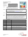
Drive Application Software
Application Set
Application Set Title
Drive Product
File Name for (AS)
Date / Revision
TorqProve™ - Vertical Drop Lift with Encoder
PowerFlex® 700 Vector Control
AS PF700 VDL TorqProve.doc
12/13/04
-
01
Attention:
This document and related file(s) are designed to
supplement configuration of the listed drive product. The
information provided does not replace the drive products
user manual and is intended for qualified personnel only.
Description:
Programming drive using TorqProve for a counterbalanced vertical drop lift with an encoder.
PLC was used to send digital signals to drive for starting and stopping as well as two speed set
points. A slow speed was used to creep into position via a limit switch to the PLC.
Reference Application Brief Publication:
PowerFlex 700 App Brief-Vertical Drop Lift, 20B-AP003A-EN-P – April 2005
Limitations:
Options &
Notes:
ATTENTION: To guard against personal injury and/or equipment damage caused by
unexpected brake release, verify the Digital Out 1 brake connections and/or programming.
The default drive configuration energizes the Digital Out 1 relay when power is applied to the
drive. The PowerFlex 700 drive will not control the mechanical brake until TorqProve is
enabled. If the brake is connected to this relay, it could be released. If necessary,
disconnect the relay output until wiring/programming can be completed and verified.
Drive Input & Output Connections:
Inputs
Function
DI 1
4 - Stop - CF
DI 2
8 - Run Forward
DI 3
9 - Run Reverse
DI 4
15 - Speed Sel 1
DI 5
(0 - Not Used)
DI 6
1 - Enable
AI 1
AI 2
Outputs
Function
DO 1
4 - Run
DO
DO
AO
AO
19 - Motor Overload
1 - Fault
2
3
1
2
AS_PF700_VDL_TorqProve.doc
Form Revision – A
Page 1 of 2
Description
P361
P362
P363
P364
P366
Not Used
Not Used
Description
P380 - Brake relay output. Only terminals 12 & 13 should be used.
When TorqProve is “enabled” in P600, Relay 1 is dedicated for brake
control only. (All other programmed selections are ignored.)
P381
P382
Not Used
Not Used
Drive Application Software
Application Set
Parameter Configurations
Changes from Default Parameter Settings (Any listed defaults are in gray.)
Par
Name
Value
Link
Description
per
41(Data entered per motor nameplate)
Motor NP . . .
nameplate
45
4 - “FVC
53
Motor Cntl Sel
Vector”
80
Feedback Select
3 - “Encoder”
Must use quadrature and differential encoder
11 - “Preset
90
Speed Ref A Sel
Spd1”
12 - “Preset
93
Speed Ref B Sel
Spd2”
101
Preset Speed 1
60 Hz
102
Preset Speed 2
12 Hz
140
Accel Time 1
2.0 Sec.
Affected by desired cycle time and system Inertia
142
Decel Time 1
2.0 Sec.
Affected by desired cycle time and system Inertia
146
S Curve %
20%
Used to smooth accel / decel profile
Bit 8 = 1
Bit 8 enables Input Phase Loss and bit 12 enables
238
Fault Config 1
Bit 12 = 1
Output Phase Loss (Internal value = 4426)
436
Pos Torque Limit
120%
Limit was used to protect machine in event of a jam.
Typical range will be 20-40 rad/sec. Adjusting this will
449
Speed Desired BW
35 Rad/Sec.
automatically change Parameters 445 and 446
For Reference Only. Automatically adjusted when
445
Ki Speed Loop
(39.9)
Parameters 449 is changed.
For Reference Only. Automatically adjusted when
446
Kp Speed Loop
(4.6)
Parameters 449 is changed.
447
Kf Speed Loop
0.1
For Reference Only. Automatically determined during
450
Total Inertia
(0.13 Sec)
inertia autotune. (Note: Kp = BW x Inertia)
***
TorqProve Settings
600
TorqProve Cnfg
601
TorqProve SetUp
602
Spd Dev Band
603
604
605
606
607
608
609
610
611
Spd Band Integrator
Brake Release Time
ZeroSpdFloatTime
Float Tolerance
Brk Set Time
TorqLim SlewRate
BrkSlip Count
Brk Alarm Travel
MicroPos Scale%
AS_PF700_VDL_TorqProve.doc
Form Revision – A
Page 2 of 2
Bit 0 = 1
0
3.0 Hz
100 mSec.
0.01 Sec
0.1 Sec
0.1 Hz
0.10 Sec
1.0 Sec
10 Revs
1.0 Rev
10 %
This “enables” TorqProve and Digital Output 1 will
now control the mechanical brake (Note: this is not
changed when “Reset to Defaults”)
Default – used only if using communications to control
TorqProve parameters.
This was used to protect machine in event of a jam. It
may need to increase depending on application.
May need to increase depending on application.
Set to minimum since these lifts rarely need float.
Set to minimum since these lifts rarely need float.
Default
(Note: This may be too low for some applications)
Default
Default – not used in this application