1
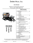
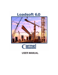
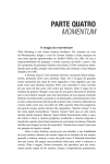
GuvenCE EMERGENCY RESCUE SYSTEM USER MANUAL Serial No:………. Guide Version: 2.01 (HV: 2.01, SV: 2.01) NOTE: This guide is prepared for the hardware version 2.01 & software version 2.01. Different version product functionalities may be changed. Please be sure to check the compatibility of your product manual. Manufacturer Asronik Asansör ve Elektronik Ltd.Şti. Fevzi Çakmak mah. 10569. Sok. No.26 Karatay / Konya / Turkiye Tel: +90.332 342 41 39 Fax: +90.332 342 41 43 e-mail: [email protected] www.asronik.com Service Line Author Date of issue 2 Tel: +90. 531 686 08 81 ZD 09.12.2012 Hardware Version V2.01 Software Version V2.01 or newer Copyright This manual is protected by copyright. All rights of this document belong to the publisher. Without publisher’s permission, this document can not be copied or distributed. Version: 2.01 | www.asronik.com TERMINAL NUMBERS AND MEANINGS IN GuvenCE EMERGENCY RESCUE SYSTEM: UPS Faz, UPS Notr : UPS Power Input (220VAC) U,V,W : Motor Output, CMA, KA CMK, KK FR1, FR2 : KA relay normally open contact output, : KK relay normally open contact output, : FR relay normally closed contact output, DI DO AC KP KG HP+, HP1000 100 : Programmable digital input (PNP input, 24VDC), : “Rescue Control” digital output (PNP output, 24VDC), : Programmable digital input (PNP input, 24VDC), : Programmable digital input (PNP input, 24VDC), : “Run Rescue” digital input (PNP input, 24VDC), : Speaker output (8 ohm, 0,5W) : 24VDC (gnd) : 24VDC USED FUSES AND FEATURES IN GuvenCE EMERGENCY RESCUE SYSTEM: GuvenCE Emergency Rescue Board has two fuses, which coded by F101 and F102. F101 is for 24VDC power supply, in other words, it connected on the way of 100 and 1000 labeled 24VDC power input terminals and its value is 1A. F102 is on the motor current way and its value is 10A. When any one of these fuses was blown, first check the panel wiring. Remove all terminals on GuvenCE and confirm the appropriate voltages on the corresponding terminals. Then GuvenCE must be controlled visually. Shutdown the UPS and electric network before replaces the fuses. Then wait for discharging the capacitors on the GuvenCE. To make sure discharging the capacitors, follow the "DC bus" labeled LED. It must be completely off. There are high voltages on the GuvenCE, which are dangerous for human life. Don't do anything before take ! precautions above mentioned Remove the Plexiglas after DC bus LED completely off. Replace the fuses with absolutely correct value fuses. ! Never wrap wire around fuses. Because products will be out of warranty. If the fuses blown again and again, please contact with ASRONIK without any further action on GuvenCE www.asronik.com | Version: 2.01 3 Dear Valued Client, Thank you for purchasing the GuvenCE Emergency Rescue System developed using advanced power electronics technology. Our mission is to present our product in the best possible performance and satisfactory operation. In this respect, it was designed in our modern establishment and tested utilizing modern quality control methods. We highly recommend reading this document before installing, as it contains important information from operation to detailed troubleshooting tips and solutions. WARNING This manual was designed to provide helpful operation and maintenance tips for personnel who are knowledgeable and educated on electric circuits of lifts. Installation company is responsible for the knowledge and ability of installing personnel. Manufacturer is not responsible or liable for any damages that result from the misuse of, or the inability to use of the product. For your own safety, alterations and modifications are not allowed on the product. Personnel installing the GuvenCE Emergency Rescue System are themselves responsible for any damages they may harm. Complying with the legal regulations and safety rules are mandatory to avoid any harm to install and service personnel and product. This user manual being a part of the product should be kept near the installation for ready reference. WARNING In this manual, the connections establishment of GuvenCE Rescue systems, their operations, the possible problems, troubleshooting tips and solutions are explained. But when necessary, the manufacturer should be consulted. 4 Version: 2.01 | www.asronik.com WARNING This lift has GuvenCE Emergency Rescue System. In case of a power failure or blackout, GuvenCE Emergency Rescue System automatically activates and lowers or elevates the lift to floor level to provide for the safe exiting of the passengers. Warning for technical personnel undertaking the maintenance of the lift: For your own safety, disconnect the GuvenCE Emergency Rescue System during the maintenance of the lift. For this reason, turn off the UPS MCB’s. Otherwise, it may run out of your control in case of power failure. For a longer UPS life, we recommend operating the system several times during each maintenance work. This is important to keep the system continuously operable. www.asronik.com | Version: 2.01 5 OPERATING INSTRUCTIONS of GuvenCE EMERGENCY RESCUE SYSTEM GuvenCE Emergency Rescue System operates full automatic. It waits on standby mode when electricity is present. When the electricity interruption occurs, GuvenCE emergency rescue system automatically starts operating and shows a warning message. Cabin starts to move to the nearest upper or lower floor, stops at the floor level and open the doors. Thus, the rescue process ends. After the rescue process, it waits for electricity to be ok. Afterwards, the lift automatically starts to operate in normal operating mode. If GuvenCE emergency rescue system cannot automatically start operating and implement rescue process, it was may be cause by a malfunction either in the system or in an external connection error. After the electricity is ok, the lift return to the normal operation. NOTE: If desired, a copy of this page can be hung inside the lift cabin or somewhere the apartment administrator can reach. 6 Version: 2.01 | www.asronik.com Operation Principles of GuvenCE Rescue System with birİNCİ Controller Board: GuvenCE Emergency Rescue System, are working with birİNCİ Controller Board which is placed in control panel. So connection, commissioning and ease of use are provided. Below, both birİNCİ and GuvenCE control processes described. However, birİNCİ and GuvenCE can control main and rescue contactors separately. For this reason birİNCİ and GuvenCE, main and rescue contactor functions are described separately. After examining the connection diagram of control panel and learning which board is driving the which contactor, check the time diagram again. 1. The processes, which controlled by birİNCİ Control Board, described below. (See Figure 1) (Be sure to set birİNCİ as "Rope Lift". Addition, check the "O-Rka", "O-Rkk" and "O-Rescue" functions are adjusted correctly. For further details refer to birİNCİ User Guide). 1.1. Power failure is detected. (T1 time) (The absence of one phase mean power failure.) . 1.2. "O-Rka" function becomes active and releases the main contactor. (T2 time) (The relay that assigned as O-Rka function, is recommended to have normally closed contacts.). 1.3. If the elevator stays at the floor level, the door will open and algorithm goes to the step 1.12, else "door close" command is given and the process continues to the next step. 1.4. Waits up to time elapsed which adjusted at parameter "2.12-Rescue-StartingDelay". (S1 process). 1.5. “O-Rkk” function will activate and rescue contactor will energize. (T3 time) (The relay that assigned as O-Rkk function, is recommended to have normally open contacts.). 1.6. birİNCİ checks the safety circuit. It expects until the safety circuit is closed circuit (T4 time). When the safety circuit closed, circuit process continues to the next step. (S2 process). 1.7. It activates "O-Rescue" function. It means that giving a “Rescue Start” command to the GuvenCE (T5 moment). 1.8. During the process of S3, it expects “I-RescueControl” signal from GuvenCE. If birİNCİ senses the control signal the process continues to the next step, otherwise it gives "RescueFault!" and cancels the rescue operation. 1.9. If birİNCİ senses these control signal during the S3 process, RU1 (KU1, down direction contactor) relay and “O-Rh,Ray” function (KH, high-speed contactor) activates (T6 time). 1.10. GuvenCE will start rescue operation. Any interruption of stop or “I-RescueControl” signal or turning the lift to the inspection mode cancels rescue operation while (S4) period. Opening of the door or interruption of the lock contact stops the rescue operation immediately. However if these contacts closed again, the rescue process starts again. 1.11. When the elevator reaches to floor (T7 time), birINCI deactivates the "O-Rescue" function and gives stop signal to the GuvenCE. In addition, RU1 relay (KU1, down direction contactor) and "O-Rh,Ray" function (KH, high-speed contactor) deactivates. It applies "Door Open" command. 1.12. When electricity is ok (T8 time), birİNCİ activates the main contactor and return to normal operation. www.asronik.com | Version: 2.01 7 Function Power failure Yes No Active O-DoorXClose function Passive Active O-DoorXOpen function Passive O-Rka function Active Passive Active O-Rkk function Safety circuit O-Rescue function I-Rescue Control RU1 relay Passive Close Open Active Passive Active Passive Active Passive O-Rh,Ray function Active Passive Time Reaches to the floor level Figure 1: Process controlled by birİNCİ Controller. 2. The process which controlled by GuvenCE Rescue described below. (See Figure 2). 2.1. GuvenCE detects "Run Rescue" signal. (T10 time). 2.2. FR relay energizes. (T11 time) Thus traction machines mechanical brake does not release if KU1 (down direction contactor) and KH (high-speed contactor) energies. 2.3. KA relay energizes. (T12 time). 2.4. KK relay energizes. (T13 time) (Rescue contactor activates.) 2.5. GuvenCE gives “Rescue Control” signal through S5 period. 2.6. GuvenCE drives the motor at T14, and releases the mechanical brake at T15. 2.7. If the traction machine does not rotate, close the mechanical brake at T16. Drive the motor again for rotates it to opposite direction at T17 and releases the mechanical brake at T18. 2.8. Through S6 and S7 periods, GuvenCE was open the mechanical brake and was drive the motor. 2.9. When the elevator reaches to the floor level, birİNCİ switch off the KG signal (T19 time) then GuvenCE activates the FR relay. Thereby mechanical brake closes immediately. 2.10. Then the KK relay (Rescue Contactor), the KA relay and FR relay deenergize respectively. 8 Version: 2.01 | www.asronik.com Function Aktif Pasif Aktif Pasif Aktif T19 T18 T17 T16 Pasif T10 Motor Run Pasif T15 DO output Aktif T14 KK Relay Pasif T13 KA Relay Aktif T12 FR Relay Aktif Pasif T11 Run Rescue (KG) Time Reaches to th fl l l Figure 2: Process Controlled by GuvenCE Emergency Rescue System. USING GuvenCE EMERGENCY RESCUE SYSTEM MENU: All parameters of GuvenCE Emergency Rescue System are numbered and grouped. Thus, is extremely easy to reach the desired parameter, and view or change values. *** MAIN MENU *** 1-Settings When GuvenCE shows the main screen press ENTER for 3 seconds to enter the menu. Press UP and/or DOWN buttons for touring in the menu. For entering to any parameter group press ENTER button. 1.1-RescueType InternalRescue For example to go into 1.group press ENTER then it shows to you "1.1RescueType" parameter. You can tour parameters by using UP and/or DOWN buttons similarly. To change selected parameters press ENTER. 1.2-TorqueSet > 100 When you press ENTER button, > symbol appears. You can change the parameter values as you want with UP and/or DOWN buttons. After you changing the value, press ENTER to confirm or press ESC to cancel. After confirming the changes > symbol disappears then new value saves to the memory and it activates immediately. Similarly, cancelling the changes > symbol disappears but old value continuous to use. Look into the schematically shown Menu Tree in Figure 3. www.asronik.com | Version: 2.01 9 MENU TREE 1.1-RescueType 1.2-TorqueSet (fact. setting=100) 1.3-ReverseRotationLimit (fact. setting=90) 1-Settings 1.4-DoorType 1.5-DoorOpeningTime 1.6-Max.RescueTime (fact. setting=30) 2.1-RescueCount 2-Reports 2.2-TotalEnergizedTime 3.1-PIN Request 3-Security 3.2-PIN Change 4.2-VersionNo 4.4-ManufacturerInfo 4-SystemInfo 4.5-DealerInfo 5.1-InternalRescueFactoryDefaults 5-ReturnToDefaults 5.2-ExternalRescueFactoryDefaults Türkçe 6-Language-Dil English Figure 3. Menu Tree. 10 Version: 2.01 | www.asronik.com PARAMETERS DESCRIPTION: 1. Settings: 1.1. Rescue Type: This parameter is only monitor able, not changeable. Look for "5-ReturnToDefaults" parameters to change it. 1.2. Torque Set: This is the turning torque of the motor. If this parameter sets to too high, the UPS will switch off to protect it selves. If this parameter sets too low, the motor can not rotate. 1.3. Reverse Rotation Limit: GuvenCE Emergency Rescue System decides the rotation of the motor by sensing the motor current (See Figure 4). If the motor current (IMotor) is smaller than “1.3ReverseRotationLimit” value percent of the motor current while the motor can not turn (IMotorNotTurn), GuvenCE thinks that motor is rotate and continues the rescue operation. In other words; I Motor I MotorNotTurn Re verseRotationLimit 100 If the motor current is bigger than this value, GuvenCE thinks that motor cannot turn and stop the motor and tries to turn the motor in the opposite direction. Motor Current I Motor IMotorNotTurn I MotorNotTurn X 1.3-ReverseRotationLimit Time FR Relay Active Passive Time Mechanical Brake Active Passive Time Figure 4: The principle of “Reverse Rotation Limit” parameter. 1.4. Door Type: GuvenCE works with all mono-phase door motors. The newer version of firmware will work with three-phase door motors. 1.5. Door Opening Time: Three-phase door motors opening time will be adjust at this parameter. New version of firmware will include this function. 1.6. Max. Rescue Time: This parameter identifies maximum rescue time. This period shall be long enough for elevator to reach the next floor. Too big values are not suitable for safety reasons. It shall adjust according to the longest floor-to-floor distances. www.asronik.com | Version: 2.01 11 2. Reports: 2.1. Rescue Count: This number indicates the rescues counts that have been undertaken successfully since the GuvenCE Emergency Rescue System started to run. Changes are not allowed. 2.2. Total Energized Time: Define total run time in hours for GuvenCE Emergency Rescue System. Changes are not allowed. 3. Security: 3.1. PIN Request: You can activate PIN request by assigning a password to prevent to seeing or changing the parameters by unauthorized persons. If the password was already set, you shall enter the correct password to turn it off. If you want to activate the password query, first you shall set your password successfully. Otherwise, password request does not activate. There is no password on factory defaults. NOTE: If you enter an incorrect password 5 times consecutively, GuvenCE blocks itself. The rescue operation continues to work but only accessing the parameters are disabled. When your password blocked, GuvenCE gives a key number that appears on the LCD. Call to Asronik, tell this key and get the PUK number. Then enter the PUK to activate GuvenCE Rescue Board again. 3.2. PIN Change: GuvenCE displays this menu only the password activated. You can change your password in this menu. To changing the existing password, first enter the current password than enter the new password. GuvenCE wants to enter the new password again for confirmation. After this process, "PIN Changed" message appears. Then the new password will be activated. 4. System Info: 4.2- Version No: This parameter shows to you the firmware version number. 4.4- Manufacturer Info: This parameter shows to you the contact information’s of the Asronik. You can reach all information’s of manufacturer with entering UP and/or DOWN buttons. 4.5- Dealer Info: This parameter shows to you the contact information’s of the your local dealer. You can reach all information’s of your local dealer with entering UP and/or DOWN buttons. 5. Return To Defaults: 5.1. Internal Rescue Factory Defaults: This parameter returns to factory settings for the application that birİNCİ & GuvenCE works together. 5.2. External Rescue Factory Defaults: It considered for external rescue panel applications. All the functions described in this user manual are for application that birİNCİ & GuvenCE works together in same panel. For different applications please contact Asronik. 6. Language-Dil: You can select the language of messages on the LCD from this parameter. Turkish and English languages are standard languages in the firmware. 12 Version: 2.01 | www.asronik.com IMPORTANT NOTES: 1. GuvenCE Rescue System voltages are dangerous to human life. Do not interfere to any cables during the power-on. Do not touch the PCB with bare hands. Do not make short-circuits. 2. If the control panel power switches off for a long time, switch OFF the UPS MCB’s. 3. If GuvenCE Rescue System disassembly required, disconnect all cables and wait 5 minutes to discharge the capacitors. 4. For the motor connections, use at least 2,5mm2 NYAF cable. This requirement reduced cable losses that necessary and important for system working. 5. We are spending many times for debugging the mistakes from the user manual and diagrams. But may be there are some bugs. The users should review the manuals with these principles. Please inform us immediately if you encounter a bug in the document. We will debug these mistakes in the new documents. FAULT CODES: GuvenCE Rescue System detects the faults by shows them on the LCD. It helps to users for troubleshooting the failures easily. The fault codes are as following. Rescue Cancel: After activating the KG input, GuvenCE performs some preliminary preparation to start the rescue process. If the KG input deactivated before starting the rescue process, GuvenCE cancels the rescue operation and gives this message. Could Not Rescue: GuvenCE gives this fault if it can not turn the motor in both directions. Check "1.2TorqueSet" and " 1.3-ReverseRotationLimit" parameters. Driver Fault: It indicates a fault in inverter stage. In this condition, rescue process cannot be implemented. Please contact Asronik. Fuse Blown: It indicates that motor fuse which located on GuvenCE was blown. In this condition, rescue operation cannot be continuing. Replace the motor fuse with 10A glass fuse. Motor Not Connected: Safety is always the first consideration for GuvenCE while implementing the rescue operation. In the beginning of rescue operation, a voltage applies to the motor. If motor draws current than the limit value then mechanical brake releases and rescue operation starts. However, if the motor does not draw any current then the brake does not release and “MotorNotConected” error message shown and rescue operation ends. Check motor connections, pulling of KU1, KH contactors during rescue operation. www.asronik.com | Version: 2.01 13 7 6 5 4 3 3OÿP40ÿÿÿ4ÿÿ 2NOÿP40ÿÿÿ 8 S&!ÿ(Z3Q S&!ÿ272 4 7 Q7 U7 5# 7 $$$%# 4%+ Q7 S&!ÿ07 Q7 Q 7 &( Sÿ&ÿ! 1` &abb̀( 7X0001 75 P 5#ÿQ%Y 75 W U7 UU US 0,.ÿ!+ $ÿ!+ /Vÿÿÿ/Vÿÿÿ/V 2 7 75 75 W P US US[ 9 U0[ U2[ 5ÿ& 3#,%"ÿ!+ÿ &).*) \[]ÿOÿ5%ÿ#)ÿ*ÿ75Mÿ"+ÿ$.ÿ0175ÿ%ÿ3.ÿ Q5ÿYÿ.)ÿ*ÿ%%ÿÿ%%ÿ% US[ (009 US 7ÿ7 ÿÿ3ÿ&'%ÿ(# 2ÿ)*ÿ+ÿ,ÿ#-ÿ$.ÿ*/(5/ÿ%ÿÿ01ÿ1)53ÿ%)-ÿ%ÿ+ÿ%%ÿ,# 3ÿ5ÿ!"# 4$,ÿ(# 5 ÿÿ+$ÿ%%) 0+ 0+ 2 54 1c53 Q%)ÿ6 S 1 T 5R7 U7 5RU UU 2Q 2Q 4/ 4Z 75 U& U1 0&P 0&M 000 00 UR+ U0 0 017 0 R+ Q ! 3 1 Rÿ&%ÿ 5%)ÿ6 US 3.#ÿQ" U0 S 1 T 7X0001 75 W 0 1 17 7 75 P 0 145ÿQ%Y 4 17 0 0#7 0 01 7X Q54 0017 7 0 &ZM &ZP 2 U2 S 1 T 7X0001 6ÿQ%Y U0 U2 US US 2QM 2QP 1, U2 0 0 0 0 60 U7 UU US US /+%ÿ $%. 60 600 600 54 60 *_(5_ Yÿ5 UU[ 3.ÿ+#ÿ.)ÿ*ÿ ') M&.5ÿdÿef MQ.ÿQ"ÿdÿZMQ.-Q"f MQYÿQ"ÿdÿZMQY-Q""f MQNÿQ"ÿdÿZMQ%)f MQÿQ"ÿdÿZMQf MQÿQ"ÿdÿZMQf MQÿQ"ÿdÿZMQf 9MQÿQ"ÿdÿZM4Z+f 8MQ%ÿQ"ÿdÿZM45f M4(ÿdÿ5%f M4(ÿdÿ5%f M4(ÿdÿ/MQ%)5f U7[ 6 5 4 3 2 1 0 ÿ5%ÿ60ÿÿ600ÿ%ÿM*"Mÿ$.ÿ0gÿYN*ÿ%* ÿ5%ÿ60ÿ%ÿ$.ÿ0gÿYN*ÿ%*ÿ\5,ÿ#ÿ*ÿÿÿ)ÿÿ.ÿ$,] 3.ÿ%ÿÿ+%ÿÿ.ÿ*/(5/ÿ%ÿÿ#ÿ* 7 4$ 24 5.% !0 56789:;ÿ=7 >?@ABCDAEFAGHIIJAJKJL 3. 0400 1)+ 4M502M6/M11NNNMNNN &, 0 0 40 0 7 6 9 5 4 3 2 1 65 1 4$ 0 8 US US U0 0 0 40 0 7 6 5 4 3 2 1 65 1 Q ! 3 07 0 0 0 7 6 QSXQ. QSXQ". Q.XQ" QYXQ"" Q^ Q^ Z 7 (5 5ZR (Z U U U U4 U S+ R R R R R R R0 R0 88 88 89 89 80 80 4( 4( 4( 4( 4( 4( U0 U0 43! 43! 8 9 8 9 8 4 8 9* 00 00 0 0 &35 UQ5 &35 00 41 41 00 000 U2 U0 44 U7 00 000 UU U U4 U U U Asronik Asansör ve Elektronik Ltd.Şti. Fevzi Çakmak Mah. 10569. Sok. No:26 Karatay / Konya / Türkiye Tel: +90.332.342 41 39 Fax: +90.332.342 41 43 AB UYGUNLUK BEYANI EC- DECLARATION of CONFORMITY İMALATÇI / MANUFACTURER : TİP /TYPE : ASRONiK Asansör ve Elektronik Ltd.Şti. GüvenCE İMALATÇI ADRESİ / MANUFACTURER ADRESS : ÜRETİM YILI / YEAR OF MANUFACTURE : Fevzi Çakmak Mah. 10569. Sok. Etiket Üzerinde / See data label on product No:24 Karatay / Konya / Türkiye ÜRÜNÜN ADI / PRODUCT NAME : SERİ NO / SERIAL NUMBER : Acil Kurtarma Ünitesi / Emergency Rescue Unit Etiket Üzerinde / See data label on product UYGULANAN STANDARTLAR / THE FOLLOWING STANDARTS : EN 81-1+A3, EN 81-2+A3 UYGULANAN DİREKTİFLER / THE FOLLOWING DIRECTIVES : Asansör Direktifi 95/16/AT / Lift Directive 95/16/EC Üzerinde seri numarası yer alan ürün için, kullanıcıya We declare eligibility of above mentioned standards teslim edilen kullanım kılavuzundaki şartlara and directives to comply with the represented uyulması durumunda yukarıda belirtilen standartlara conditions on the user manual for the serial number ve direktiflere uygunluğunu beyan ederiz. on the product. FİRMA SORUMLUSU / RESPONSIBLE OF COMPANY : Elk.Elt.Yük.Müh. Zafer Dedeoğlu YER–TARİH / PLACE-DATE : KONYA / TÜRKİYE / 09.12.2012 YETKİLİ İMZA / LEGALLY BINDING SIGNATURE :