1
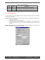
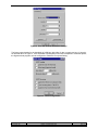
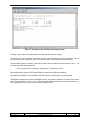
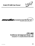
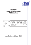
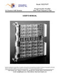
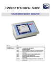
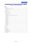
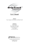
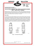
Jtech J - Te c h E n g i n e e r i n g , L t d . 11080 Bond Boulevard Delta BC V4E 1M7 Canada Tel: 604 543 6272 Fax: 604 543 6476 http://www.jtecheng.com engineering ltd AUTODIALER USER’S MANUAL REVISION HISTORY Date Rev. Details Author 07.05.03 1.0 Initial Release. Lawrence Johnson 04.03.04 1.1 Removed unneeded sections. Lawrence Johnson 26.10.05 1.2 Added information in support of alternate baud rates. Lawrence Johnson TABLE OF CONTENTS 1. 2. 3. 4. INTRODUCTION ..........................................................................................................................................2 SYSTEM OVERVIEW ...................................................................................................................................2 HARDWARE DESCRIPTION ..........................................................................................................................3 SYSTEM CONFIGURATION ..........................................................................................................................4 LIST OF TABLES TABLE 1. INDICATOR DESCRIPTION. ..................................................................................................................4 LIST OF FIGURES FIGURE 1. TIMING DIAGRAM. ............................................................................................................................3 FIGURE 2. TERMINAL EMULATION SETTINGS......................................................................................................4 FIGURE 3. PORT AND TERMINAL EMULATION SETTINGS. ....................................................................................5 FIGURE 4. ASCII CONFIGURATION. ..................................................................................................................5 FIGURE 5. CONFIGURING THE AUTODIALER WITH HYPERTERMINAL.....................................................................6 Rev 1.2 Doc #:ADLR –UM Autodialer User’s Manual 2005 - J-Tech Engineering, LTD. Date: 27/10/05 8:36 AM Page 1 of 6 1. INTRODUCTION The Autodialer has been designed to add dial-out capability to a device not capable of generating AT dialing commands. Successful operation of the Autodialer requires the following conditions be met: • The device originating the call is capable of asserting a signaling lead (i.e. RTS, radio PTT etc) before sending a message. • The device originating the call has a message re-send facility, with configurable number of, and time delay between, retry attempts. • Either the modem or the far-end equipment is able to drop the link. The Autodialer is placed in-line between the DTE device and the modem. Connectors are standard EIA-232 9-pin dSUBs. The Autodialer will not interfere with RX data from the modem, or DTR, DSR and RI signaling leads. The Autodialer will block TX data from the DTE device to the modem when no connection is established. RTS and CTS signaling leads are passed through when a connection is made. 2. SYSTEM OVERVIEW All settings in the system should be carefully reviewed before any decisions are made. System performance should be evaluated for bad and worst case scenarios. Getting the Autodialer to work when the far end answers immediately and a connection is established quickly is relatively simple. The true test is to have an unsolicited message report when the first few connection attempts are unsuccessful. As an example, consider implementing the Autodialer in a land-line dial-up scheme. When the DTE device has data to send, it calls the master station, waits for a connection (indicated by DCD), and transmits data once the connection has been made. If a connection cannot be made, the device hangs up the modem, waits a set amount of time, and redials. After a number of redial attempts, the device gives up, as its data is no longer useful or current. In the above example, the DTE device does not have the ability generate a dial string, wait for DCD before transmitting data, or hang up the modem. A typical configuration is as follows. DTE device data transmit retries are set to three with a retry interval of 20 seconds. Autodialer connection timeout is set to 45 seconds. Ideally, the operation would be as follows: Dialing is initiated when the DTE device asserts RTS. The Autodialer blocks any data coming from the DTE device, and sends the dial-string to the modem. The DTE’s second attempt at sending data (20 seconds later) is also blocked as a connection has not yet been established. Twenty-five seconds later, a connection is finally made. The Autodialer will now pass TX data from the DTE device. The master and slave communicate on the second retry attempt. After 60 seconds of idle time, the master hangs up the remote modem, causing the local modem to detect loss of carrier and disconnect. Now consider what would happen if the DTE device’s second retry attempt failed. The Autodialer times out at 45 seconds. During this time, the DTE device has attempted to transmit data three times. The Autodialer may establish a connection on its second attempt, but the DTE device no longer attempts to send data. The above example shows that retries will need to be a minimum of one for any chance of successful data transmission. In reality, one retry is lost on every dial attempt. Rev 1.2 Doc #:ADLR –UM Autodialer User’s Manual 2005 - J-Tech Engineering, LTD. Date: 27/10/05 8:36 AM Page 2 of 6 A typical sequence is shown in Figure 3. For illustration purposes, a connection is never successfully made. 1st Attempt Retry #1 t=0S t=20S Retry #2 t=40S Dial Attempt #1 Dead time while connection is established. Retry #3 t=60S Retry #4 t=80S Retry #5 t=100S Dial Attempt #2 Zone where connection has likely been established. First retry should occur here. Retry #6 t=120S Retry #7 t=140S Retry #8 t=160S Dial Attempt #3 Connection will have been made or call dropped. One retry scheduled in case of long connect time or second attempt was corrupt. Figure 1. Timing Diagram. To correct the problems of the previous example, DTE device data transmit retries should be set to eight, retry interval to 30 seconds, and Autodialer connection timeout should be set to 70 seconds. The result is two data transmission attempts per dial attempt, and three dial attempts in total. Four minutes elapses between the first and last attempt. Note that the modem should be configured to give up a call attempt at 45 seconds. In the event that the modem at the far end answers but does not connect properly, the master end should be configured to hang up after 60 seconds. This will still allow three redial attempts in most cases. Times can be adjusted as required, however the above sequence works well for most situations. Modems should be configured to disconnect if no data has been sent for a time longer than the total time duration of Figure 3. This will help avoid the situation of the remote modem being powered up and connected to the phone line, and the master end device disconnected or not generating hang up commands. The link may otherwise stay connected indefinitely. On power up or device reset, the Autodialer sends a carriage return to the modem to clear the modem’s input buffer. 3. HARDWARE DESCRIPTION The power supply input voltage should be in the range of 8-28 VDC. No SWC protection is provided, the Autodialer should be powered from a protected DC source. The Autodialer does not provide electrical isolation between the EIA232 ports and the applied DC power source. This should be considered when selecting the source of power. EIA232 transceiver is not capable of providing power to port powered isolators. All data inputs and outputs are protected against static discharge and HV transients. Switch SW1 provides reset of the microcontroller without power down. The microcontroller has an in-built watchdog timer to allow recovery from unforeseen software lockups. Switch SW2 provides manual initiation of a TX dial string, and in combination with SW1 is used to enter programming mode. Three LEDs are provided for visual indication of the state of the Autodialer. The STATUS LED indicates that the microcontroller is running properly. It flashes at a rate of 0.5 Hz when the Autodialer is idle, and 5 Hz when the Autodialer is establishing a connection. When a connection is established, the STATUS LED will continue to flash at 5 Hz, plus the LINK LED will come on. The DTE-RTS LED indicates the status of the DTE-RTS signaling lead. Rev 1.2 Doc #:ADLR –UM Autodialer User’s Manual 2005 - J-Tech Engineering, LTD. Date: 27/10/05 8:36 AM Page 3 of 6 Table 1. Indicator Description. Name Colour Description STATUS RED Indicates the current operating state of the Autodialer. DTE-RTS GREEN Indicates transmission activity during normal operation. LINK YELLOW Indicates if a link has been established with the remote modem. 4. SYSTEM CONFIGURATION To enter configuration mode, hold down the Test button (SW2) while resetting (press and release SW1) or powering up the Autodialer. Programming features through terminal emulation software requires the following three conditions be met: 1. Jumper JP1 is installed; 2. Nothing is plugged into the modem port (J3); 3. A standard serial-port cable is connected from J2 to a host PC. If an RS-232 port is not available, as is the trend with notebook computers, a USB-RS-232 adapter may be used as a substitute. Although Hyperterminal is used in the following example, any terminal program can be used for this purpose. Typical settings for Hyperterminal are as follows: Figure 2. Terminal Emulation Settings. Rev 1.2 Doc #:ADLR –UM Autodialer User’s Manual 2005 - J-Tech Engineering, LTD. Date: 27/10/05 8:36 AM Page 4 of 6 Figure 3. Port and Terminal Emulation Settings. The factory speed setting for the Autodialer is 9,600 bps, with 8-bits of data, no parity and one (1) stop bit, as reflected above in Figure 3. If the Autodialer’s speed (Bits per second) is adjusted to a different speed, the Hyperterminal program must be configured to match the new speed setting. Figure 4. ASCII Configuration. Rev 1.2 Doc #:ADLR –UM Autodialer User’s Manual 2005 - J-Tech Engineering, LTD. Date: 27/10/05 8:36 AM Page 5 of 6 Figure 5. Configuring the Autodialer with Hyperterminal. Pressing <enter> without any data present will retain previously saved settings. Connection time-out is specified in seconds, with the minimum being one second. Entering a value of zero will result in one second, any value over 255 will result in a 255 second connection timeout. Communication speed is chosen by selecting a number from the table listed after Speed (bps):. Do not enter the actual desired baud rate. i.e. Do not type ‘9600‘ for 9600 bps, simply press ‘7‘ followed by <enter>. After programming, press the TEST button (SW2) to display the configured dial string. Note that the LINK LED on the Autodialer will flicker while the microprocessor is receiving data. Configuration changes are stored in EEPROM memory, along with a checksum to indicate if the data is valid. The message ‘EE Write Fail‘ will be displayed if written data does not match the checksum. If this message re-occurs, it likely indicates a faulty microprocessor. Rev 1.2 Doc #:ADLR –UM Autodialer User’s Manual 2005 - J-Tech Engineering, LTD. Date: 27/10/05 8:36 AM Page 6 of 6