1
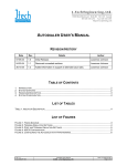
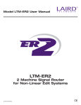
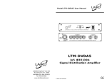
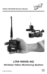
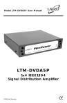
Model LTM-1400 User Manual
LTM-1400
Multiformat 1x4 Assignment Router / DA
(Component, Y/C, Composite, Balanced Audio, RS422)
© 2001 Laird Telemedia.
CE
LTM-1400
Multiformat 1x4
Assignment Router / DA
(Component, Y/C, Composite, Balanced Audio, RS422)
GENERAL DESCRIPTION
The LTM-1400 is a Multi-format Assignment Router/Distribution Amplifier System for the most complex
Multimedia signal management. It accepts 3 Video Formats: Component, Y/C & Composite, as well as 2-Channel
Balanced Audio and RS422 Machine Control.
Each format can be separately controlled by front panel switches to perform as a 1x4 switcher or as a 1-4 DA. The LTM-1400 is
an advanced multi-format A/V signal 1x4 router with RS422 capability. The most unique feature of the LTM-1400 is the ability to be converted into a Single input by four output signal distribution amplifier. Based on Laird’s proprietary control circuitry systems, the LTM-1400 is powerful, flexible and very easy to operate.
RS232 external control & downloadable Windows software provides PC-based control via its serial port. A unique
embedded address allows up to Five (5) LTM-1400 to be controlled by one PC.
The LTM-1400 operates on 110/220 Volts with an automatic switching power supply, and will process NTSC, PAL, PAL-M,
PAL-N and SECAM signals. It is housed in a 2RU cabinet.
- Page 1 800-898-0759 • 845-339-9555 • 2000 Sterling Road • Mount Marion, NY 12456 • www.lairdtelemedia.com
LTM-1400
Multiformat 1x4
Assignment Router / DA
(Component, Y/C, Composite, Balanced Audio, RS422)
SWITCHER OPERATION
Setting the Operational Mode
A toggle switch located in the center of the front panel sets the operational mode of the LTM-1400. This switch must be
set in the desired mode BEFORE power is turned on. If the mode of operation must be changed after power up, the unit
must first be shut off, the switch changed and then powered up again. The position marked: 1X4 is the 1x4 switcher mode.
The position marked: 1-4 is the signal distribution mode.
1x4 Assignment Switcher
Set front panel toggle switch in 1x4 position. After power up, the unit will parade the entire bank of switch LEDs. This is a
self diagnostic which when completed indicates that the unit is ready to operate. Connect all the required cables to the unit’s
rear panel. The source signal must be connected to connectors marked “INPUT”. The destination signals must be connected to connectors marked “OUTPUT”. Please pay careful attention to the nomenclature of the rear panel. It is clearly marked
for ease of connections.
RS422 Switching Section
The RS422 section is a single 1x4 switcher. Select where you want RS422 control. Be aware that despite the fact that the
LTM-1400 can handle a total of 12 devices for video(all 3 formats), and 4 devices for audio, the RS422 section is designed
for only 4 devices. Therefore, select the four devices which need RS422 control and plug the 9-pin cables into the corresponding port on the rear panel. Plug the RS422 controlling device (editor NLE) into the RS422 I/O port. The front panel
switches also control the RS422 switching as a “secondary priority protocol”. This will be explained below.
Tagging RS422
As discussed previously, there is only one 1x4 RS422 section. This means that only 4 machines at any time can be assigned
RS422 control to the controlling device. Select the machines which require RS422 and plug their 9pin Dsubs into the similarly marked numbered position to match the machine. Example: VTR#1 Component has RS422, VTR#2 Component has
RS422, VTR#3 YC has RS422, VTR#4 YC has RS422. Now connect The RS422 for VTR#1 to 9pinDsub#1, VTR#2 to 9pin#2,
VTR#3 to 9pinDsub#3, VTR#4 to 9pin Dsub#4. Now the front panel control switches will work as follows: The first press
will enable the primary function: switching Video(component-YC-composite) and Balanced audio as a 1x4 assignment.
Pressing the button the second time will tag the RS422 connected to that port. Pressing the button a third time clears the
switch and disables all signals.
In the event all four Component VTRs are used and they all have RS422, then the RS422 feature is now dedicated to the
Component VTRs and are not available for any other device. If any other switch is pressed twice, the RS422 will switch away
and treat that switch as priority. Likewise if that switch is pressed on a different platform switch bank, then that bank and
that number will take priority.
Balanced Audio Switching
The LTM-1400 is equipped with a 1x4 dual channel balanced audio switcher. You may choose which signal needs audio and
correspond that output with audio. The LTM-1400 does not have audio for every video format, since that would require 12
channels of audio. However, since every video feed does not require audio, you can pick and choose where complimentary
audio is required and connect it accordingly.
- Page 2 800-898-0759 • 845-339-9555 • 2000 Sterling Road • Mount Marion, NY 12456 • www.lairdtelemedia.com
LTM-1400
Multiformat 1x4
Assignment Router / DA
(Component, Y/C, Composite, Balanced Audio, RS422)
DISTRIBUTION AMPLIFIER OPERATION
1x4 Distribution Amplifier Operation
Set front panel toggle switch in 1-4 position. After power up, the unit will parade all of the switch LEDs. This is a self diagnostic which when completed indicates that the unit is ready to operate. The 1-4 Distribution amplifier system connects the
input signal to all four outputs simultaneously. By pressing any button of each switch bank, the DA mode for that bank is
enabled and all the LEDs will illuminate. To disable the DA mode, just press any button and the LEDs will go out.
OPERATIONAL NOTES
The LTM-1400 product has been developed for use in broadcast facilities. All standards and performance specifications are
designed for broadcast equipment. Balanced zero offset signals are necessary in most cases for proper operation. Signals
with high DC offset will not pass properly. Audio signals should be balanced at 0dBm. The LTM-1400 is set for unity gain
for balanced audio. Should it be required to handle unbalanced signals, it is possible to use an adaptor XLR to RCA cable
where the negative phase pin of the XLR is grounded.
Should it required to add more audio distribution to the LTM-1400 it is advised that the LAIRD LTM-ADA6 be used to provide a equal quality balanced signal distribution capability.
When using a PC for serial control, a standard 9-pin male to female cable may be used up to distances of 100 feet.
Programmers who wish to write their own control code may contact Laird Telemedia Technical Support at 845-339-9555,
Monday - Friday, 10AM to 4PM EST.
- Page 3 800-898-0759 • 845-339-9555 • 2000 Sterling Road • Mount Marion, NY 12456 • www.lairdtelemedia.com
LTM-1400
Multiformat 1x4
Assignment Router / DA
(Component, Y/C, Composite, Balanced Audio, RS422)
LTM-1400 IN 1X4 SWITCHER MODE
The diagrams below illustrate some typical examples of the LTM-1400 operating in switch mode. Diagram 1-A shows an
editing system’s output being routed to any one of four VTRS. Diagram 1-B shows VTR’s output being routed to various
presentation areas.
Diagram 1-A
NLE
LTM-1400
Diagram 1-B
LTM-1400
Control Room 1
Control Room 2
- Page 4 800-898-0759 • 845-339-9555 • 2000 Sterling Road • Mount Marion, NY 12456 • www.lairdtelemedia.com
LTM-1400
Multiformat 1x4
Assignment Router / DA
(Component, Y/C, Composite, Balanced Audio, RS422)
LTM-1400 IN 1X4 DA MODE
The diagrams below illustrate some typical examples of the LTM-1400 operating in distribution mode.
Diagram 1-C
VHS Hi-Fi
CH 3 1:15
POWER
VHS Hi-Fi
POWER
CH 3 1:15
VHS Hi-Fi
PM
POWER
VHS Hi-Fi
POWER
PM
CH 3 1:15
CH 3 1:15
PM
VHS Hi-Fi
PM
POWER
CH 3 1:15
PM
- Page 5 800-898-0759 • 845-339-9555 • 2000 Sterling Road • Mount Marion, NY 12456 • www.lairdtelemedia.com
LTM-1400
Multiformat 1x4
Assignment Router / DA
(Component, Y/C, Composite, Balanced Audio, RS422)
1
6
13
1
Component Video (R-Y, B-Y) (YUV) Switches
2
YC Video Switches
3
2
3
4
7
5
8
14
15 16 17
Operational Mode Select for 1x4 Switcher or 1x4 Distribution
Amplifier
9
10
11
12
18
10
Component Video Input from Source Device (use provided 7-Pin to
BNC breakout cables)
11
Y/C Video Input from Source Device
12
Composite Video Input from Source Device
4
Composite Video Switches
13
RS422 Machine Control Outputs
5
Balanced Audio Switches
14
RS422 Machine Control Input
6
Component Video Output (use provided 7-Pin to breakout cables)
15
RS232 Computer Control Serial Input
7
Y/C Video Output
16
RS232 Computer Control Serial Looped Output
8
Composite Video Output
17
Utility Port
9
Balanced Audio Outputs (use provided 15-Pin breakout cables)
18
Balanced Audio Input (use provided 15-Pin D-Sub breakout cable)
- Page 6 800-898-0759 • 845-339-9555 • 2000 Sterling Road • Mount Marion, NY 12456 • www.lairdtelemedia.com
LTM-1400
Multiformat 1x4
Assignment Router / DA
(Component, Y/C, Composite, Balanced Audio, RS422)
SPECIFICATIONS
VIDEO:
4 Component: R-Y, B-Y, Y: 7-Pin Female Connector
(7-Pin Male to 3 BNC breakout cable provided)
4 YC Video: (4-Pin)
4 Composite Video: True 75Ω BNC connectors
AUDIO:
4 Dual Channel Balanced (15-Pin D-Sub Connector - D-Sub to XLR Breakout Cable Provided)
MACHINE CONTROL:
4 RS422 serial control-full duplex (per bus)
UTILITY PORT:
1 9-Pin D-Sub: Male: Controls External Modules
UTILITY:
1 9-Pin port for controlling external modules
SERIAL CONTROL:
RS232 external serial control: Control device by downloadable Windows software (Device can also be controlled by
your own control software - download & test control software at our web site. All LTM RS232 controlled products can
be set with an "IDENTITY" code which can be addressed by the Windows software.)
SERIAL LOOP:
Looped RS232 buffered output of all RS232 signals.
Video Specifications
VIDEO PERFORMANCE:
BANDWIDTH:
RESPONSE:
TILT:
OVERSHOOT:
DC OFFSET:
DIFFERENTIAL GAIN:
DIFFERENTIAL PHASE:
ADJ. CROSSTALK:
Measured with a 40 IRE 3.58Mhz sine wave a linear ramp 0-100 IRE
70Mhz unity gain bandwidth
DC - 100Mhz overall; DC - 70Mhz Baseband @ + 0.05dB
< 0.5%
< 0.15%
0V @ 1Vp-p into 75 ohm
0.01%
0.05%
-65dB tested @ 10Mhz
Audio Specifications
AUDIO PERFORMANCE:
FREQUENCY RESPONSE:
S/N RATIO:
DISTORTION:
CROSSTALK:
Measured with 1KHz 1.2Vp-p sine wave (balanced audio)
10-60KHz ±0.1dB
85dB, at specified tested center frequency for response
< 0.05%
> 110dB isolation
Enclosure and Power
POWER:
DIMENSIONS:
110/220V AC 50/60 Hz @ .5amps, Auto Switching
3.5”H x 7”D x 19”W EIA Rackmount
- Page 7 800-898-0759 • 845-339-9555 • 2000 Sterling Road • Mount Marion, NY 12456 • www.lairdtelemedia.com
LTM-1400
Multiformat 1x4
Assignment Router / DA
(Component, Y/C, Composite, Balanced Audio, RS422)
Safety Precautions
1. To prevent fire or shock hazard, do not expose this equipment to the environment of Humidity and/or
dust. Do not use this equipment in an unprotected outdoor installation or any area classified as a
wet area.
2. The operating temperature of this product must be kept between -40°C and +95°C. Direct sunlight
or an intense source of heat, direct or ambient, must not be introduced to the product either by
induction or contact.
3. Always keep the product on a stable and secure base or enclosure. Do not drop the product or subject it to sudden heavy impact.
4. Provide adequate ventilation so that thermal characteristics do not cause an increase in product temperature to resulting in overheating.
5. Do not clean the unit by using electrically conductive or corrosive chemicals. Always be certain to
unplug the unit from AC wall power before any major cleaning. Use a damp cloth only for cleaning.
6. Do not subject the product to electrical mains power over voltage: The product must be used at the
rated supply voltages indicated on the product rear panel only.
7. Do not plug the product into an overloaded electrical outlet. This may result in fire or electrical
shock.
8. Object Ingress and Liquid Entry: Never insert or push sharp metal objects into the product or use such
devices for an attempt at opening or servicing the product. Servicing should be referred to a trained
and qualified technician only. Do not allow liquid of any type to enter the unit. Do not allow the unit
to be submersed in water as this may cause a shock hazard.
9. A trained qualified technician should perform all servicing of the unit. There are no serviceable components within the unit for user access.
- Page 8 800-898-0759 • 845-339-9555 • 2000 Sterling Road • Mount Marion, NY 12456 • www.lairdtelemedia.com