1
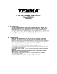
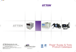
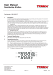
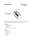
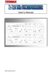
Soldering Station
TM
User’s Manual
2064549/2062627
SOLDERING STATION
Thermo-Control Anti-Static
User’s Manual
www.element14.com
www.farnell.com
www.newark.com
www.cpc.co.uk
www.mcmelectronics.com
TM
Page <1>
01/06/12
V1.1
Soldering Station
TM
User’s Manual
Thank you for purchasing the TENMA Soldering station. Please read this manual before operating the equipment.
Keep manual in accessible place for future reference.
■ Warning:
Temperature of iron tip will be up to 200°C to 400°C after connecting power, so it may lead to injury of fire because of
improper usage. Please abide the following terms:
• • • • • • Don’t touch the iron tip or surrounding metals
Never operate it near the flammable gas or substance.
Disconnect from power source if the unit will not be used for long periods. Switch off power during short breaks
Replace accessories or iron tip after turning off the station and let it cool down
Never operate this device, if you don’t have soldering experience or enough knowledge to use
Keep away from children
■ Safety Precautions:
Caution: Improper usage can cause serious injury to personnel and/or damage to equipment. For personnel safety,
please follow this precautions
• • • • • • • • Never use it to do other work except soldering
Do not subject the main unit to physical shock. Never drop or sharply jolt the unit
Don’t change the device at will
Replace loss items with original accessories of TENMA
Don’t put it in water or operate with wet hands
Don’t pull the cable but hold tightly the plug when you take it out of plug
Please keep the operate place well ventilated since soldering process produce smoke
Don’t play with other people or would be easy to hurt others or yourself
■ What’s Included
Device
Soldering Iron
Iron Holder
Power Cord
Manual
Clean Sponge
1 PC
1 Set
1 PC
1 PC
1 Copy
1 PC
www.element14.com
www.farnell.com
www.newark.com
www.cpc.co.uk
www.mcmelectronics.com
TM
Page <2>
01/06/12
V1.1
Soldering Station
TM
User’s Manual
Specifications
Input Voltage
220V AC ±10% 50Hz
Power Consumption
60W (Max.)
Temperature
Controlling Range
50°C to 450°C
1
(302°F to 842°F)
Output Voltage
28V AC
Temperature Stability
±1°C (Static)
Display
LCD
Max. Surrounding
Temperature
40°C
Calibrating Method
Digital Calibration
Temperature Range
for Calibration
0°C to -50°C
5
(122°F to -58°F)
Ground Impedance
< 2Ω
Ground Voltage
< 2mV
Heating Element
2 Cores (TENMA)
*Specifications are subject to change without prior notice.
Heating Element
2 Cores (TENMA)
Control Panel Guide
www.element14.com
www.farnell.com
www.newark.com
www.cpc.co.uk
www.mcmelectronics.com
TM
Page <3>
01/06/12
V1.1
Soldering Station
TM
User’s Manual
Introduction for LCD Display
Features
• • • • • • • New appearance design, big LCD screen, for clear and convenient reading
PID power control loop with constant temperature set by MCU computer for more precision temperature control
Imported temperature-beard materials with long life
It is convenient that the device adopt three programmable knobs in different condition.
Display the temperature between Fahrenheit and Celsius flexibly, convenient for the type of operators
Computerized temperature calibration can correct the difference between the actual and display temperature quickly
Heating element malfunction alert
Operating Guidelines
Please refer to the “Control Panel Guide” section for buttons and display panel details
1. Connection:
1.1 Insert soldering iron’s plug into the socket and tighten the nut on the plug securely and place it in iron holder
1.2 Inset station’s power cord into power plug on the back panel and plug the cord into a power source
2. Power on:
2.1 Turn on the unit
2.2 The Digital display will initially display the current set temperature (the value of last time using) for 3 seconds
After few seconds it would display the actual temperature with temp unit “°C or °F”. (Diagram 1), (Diagram 2)
www.element14.com
www.farnell.com
www.newark.com
www.cpc.co.uk
www.mcmelectronics.com
TM
Page <4>
01/06/12
V1.1
Soldering Station
TM
User’s Manual
3. Adjusting temperature:
Under normal working condition, pressing and holding button “▲” or “▲”, you can either increase or decrease the
temperature quickly. Keeping the knob in pressed will adjust the temperature setting quickly; short pressing knob, you
can adjust temp step by step. The display screen shows the temperature value simultaneously. Release knob for 3s
to store. (Diagram 3)
4. Quickly adjusting temperature
4.1 Under working condition, you can set working temperature quickly by programmable buttons. Press the button once to
extract setting temperature stored in button “1, 2 & 3”, this way you can easily set the working temperature.
4.2. Pressing button “#” and buttons “1, 2, 3”, you can store the setting temperature into fast channel knobs “1, 2, 3”.
4.3. Temperature hot key
A. Hot key 1 is usually applied to store a 200°C or lower temperature value at which level machine stands by and on rest.
B. Hot key 2 is a shortcut of temperature between 300°C to 350°C at which level a general soldering job can be done.
C. Hot key 3 is a fast channel to high temperature of 380°C specified of special welding job.
www.element14.com
www.farnell.com
www.newark.com
www.cpc.co.uk
www.mcmelectronics.com
TM
Page <5>
01/06/12
V1.1
Soldering Station
TM
User’s Manual
5. Temperature calibration
You need calibrate the temperature of tip after you replace with a new heating element or tip.
*
5.1 Enter into calibrating station by long pressing knob “ ” (>3s).
5.2. You can directly adjust the value of calibration by pressing knob “▲” or “▼”.
5.3. The value of calibration is temperature measure minus the setting. (e.g. Actual value 380°C - Setting value
350°C = +30°C. Pressing knob “▲” adds 30°C; Actual value 320°C - Setting value 350°C = 30°C.
Pressing knob “▼” minus 30°C)
5.4. The calibrating temp range is +50°C to -50°C.
5.5. You can press knob “ ” to store after you finish calibration. (Diagram 4)
*
6. Temp. unit exchange
In the power off condition, press and hold knob “#”, then turn on the station, the temp unit will be changed
between “°C” and “°F” and store automatically
7. False alarm
When “H-E” or “S-E”is displayed on the screen, there is some wrong in heating element or the circuit.
(Diagram 5,6). Turn off the unit and follow the instructions to replace the heating element.
www.element14.com
www.farnell.com
www.newark.com
www.cpc.co.uk
www.mcmelectronics.com
TM
Page <6>
01/06/12
V1.1
Soldering Station
TM
User’s Manual
Replacing the heating element
Note: Diagram (7) is soldering station 21-10115, heating element resistance about 8Ω to 10Ω
1. Power off the unit and unplug the device. Wait for the heating element to cool down.
2. Loosen the nut(1)
3. Remove the tip retainer(2) and soldering tip (3)
4. Unscrew heating contact (4), remove grouping spring(5)
5. Remove the full heat wire group (6)
6. Please reference to diagram Section (7)
7. Replace the old one the good condition heating element
8. Reverse the process to secure the heating element in the handle.
Care and Maintenance
• • • • Keep the soldering station dry; If it gets wet, dry it immediately
Use the soldering station only in normal temperature environments
Keep the soldering station away from dust and dirt
The soldering iron tip should be cleaned after use by wiping it on the damp sponge found in the soldering
iron stand. This is to get rid of burnt solder or fluxes that cause oxidation on the tip
Changing Soldering Tip
• • • • • • Always turn the power OFF when removing or inserting a tip
Let the tip to cool down to room temperature before holding it with heat resistant pads
Unscrew the metal cap nut (1).
Pull out the shaft of the soldering iron (2)
Replace it with a new soldering tip
Put back the shaft and securely lock with the metal cap nut
www.element14.com
www.farnell.com
www.newark.com
www.cpc.co.uk
www.mcmelectronics.com
TM
Page <7>
01/06/12
V1.1
Soldering Station
TM
User’s Manual
Tip out diameter Ø6.5
All tips sold separately
Dimensions : Millimetres (Inches)
Part Number Table
Description
Part Number
Soldering Station, Digital, ESD, EU
21-10115 EU
Soldering Station, Digital, ESD, UK
21-10115 UK
Tip, Chisel, 0.8mm, PK 10
21-10140
Tip, Chisel, 1.2mm, PK 10
21-10142
Tip, Chisel, 1.6mm, PK 10
21-10144
Tip, Chisel, 2.4mm, PK 10
21-10146
Tip, Conical, 0.5mm, PK 10
21-10148
Tip, Conical, 0.2mm, PK 10
21-10150
Tip, Chisel, Angled, 2.0mm, PK 10
21-10152
Tip, Chisel, Angled, 3.0mm, PK 10
21-10154
Tip, Chisel, Angled, 4.0mm, PK 10
21-10156
Tip, Conical, Micro, 0.2mm, PK 10
21-10158
Heating Element, 60W, AT938D + AT60D
CBB018722
Important Notice : This data sheet and its contents (the “Information”) belong to the members of the Premier Farnell group of companies (the “Group”) or are licensed to it. No licence is granted
for the use of it other than for information purposes in connection with the products to which it relates. No licence of any intellectual property rights is granted. The Information is subject to change
without notice and replaces all data sheets previously supplied. The Information supplied is believed to be accurate but the Group assumes no responsibility for its accuracy or completeness, any
error in or omission from it or for any use made of it. Users of this data sheet should check for themselves the Information and the suitability of the products for their purpose and not make any
assumptions based on information included or omitted. Liability for loss or damage resulting from any reliance on the Information or use of it (including liability resulting from negligence or where the
Group was aware of the possibility of such loss or damage arising) is excluded. This will not operate to limit or restrict the Group’s liability for death or personal injury resulting from its negligence.
Tenma is the registered trademark of the Group. © Premier Farnell plc 2012.
www.element14.com
www.farnell.com
www.newark.com
www.cpc.co.uk
www.mcmelectronics.com
TM
Page <8>
01/06/12
V1.1