1
15 AMP SWITCH MODE POWER SUPPLY
Model 72-8110
USER MANUAL
1. INTRODUCTION
This fixed voltage switch mode power supply is designed with high RFI stability, and is
especially suitable for two–way radio and communications equipment. The concealed
trimmer allows user fine tuning adjustment from 13.3 ~ 14.5VDC. Constant current
circuitry is used for overload, short circuit and over temperature protection. Output current
and voltage drop to a safe level when any fault occurs. This power supply also has Over
Voltage Protection to prevent connected equipment from damage.
2. PRECAUTIONS
▪Never use this power supply for high inductive load such as solenoid or motorized
equipment. The inductive kick back from the device may damage the power supply.
▪Never operate power supply immediately with a newly replaced fuse before the fault has
been found and rectified. Make sure to use the same rating and type as the original fuse.
▪Never remove the case when the supply is connected to AC or load.
▪Never touch the unit when your hands are wet.
▪Unit must be connected to a properly grounded, three prong AC outlet.
▪Refer servicing only to qualified service personnel, as incorrect re-assembly may result
in a risk of electric shock or fire
▪Power supply output provides 13.8VDC fixed output, be certain connected load accepts
this voltage
▪Never use the power supply for the load requiring higher current than the designed
value, at the risk of damage to the supply
▪Place the power supply on a flat surface with sufficient clearance, dry, dust free
surroundings for ventilation
▪Do not expose the power supply to sun, high humidity or dust levels
3. CONTROL AND INDICATORS
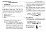
1. On/Off switch with light
2. Indicator (Green: Operate / Red:
Overload)
3. Cigarette lighter socket (10A max)
4. DC output binding post
5. Cooling fan (variable speed)
6. AC power input IEC connector
7. Fuse holder
4. OPERATION
▪Switch on the power supply, confirm that the LED indicator is green
▪Switch off the power supply
▪Confirm that equipment to be connected 13.8VDC
▪Connect the positive input of the equipment to the Red output terminal of the power
supply
▪Then, connect the negative input of the equipment to the Black output terminal of the
power supply
▪Switch on the power supply, confirm that the LED indicator is green
▪Switch on the connected equipment and the LED Indicator should still remain in green
▪You can now operate the equipment
▪When operation is finished, switch off the equipment first and then switch off the power
supply
5. FINE TUNING THE OUTPUT VOLTAGE
This regulated power supply has been factory preset at a stable DC output. Under normal
operation, there should be no need for further adjustment.
However, should the need exist for specific output voltage other than the preset value, refer to the
following procedure.
1. Let the power supply warm up for about 15 min.
2. Turn the power supply over with the bottom up and connect a digital multi-meter to the
main output terminals (4).
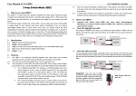
3. Locate the fine tune access hole (8) on the bottom as shown in Fig.1.
4. Insert a slim flat head screw driver to get to the trimmer as shown in Fig.1.
5. Carefully and slowly turn the screw driver clockwise or counter-clockwise to the
desired voltage setting.
6. After returning the supply to its normal operating position, measure output voltage
again.
6. SPECIFICATIONS
▪Fixed Output Voltage
▪Continuous Output Current
▪Duty Cycle Output Current (50% on/off)
▪Ripple and Noise
▪Load Regulation
▪Line Regulation
▪Input Voltage
▪Cooling Method
▪Dimensions
▪Weight
13.8VDC
15A
18A
50mVp-p
100mV
50mV
110VAC, 60Hz
Variable Speed Fan
2.5” (H) x 7.1” (W) x 7.5” (D)
3.7 lbs.
Tenma Test Equipment
www.tenma.com