1
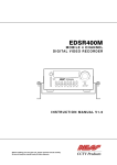
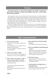
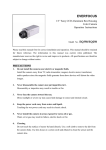
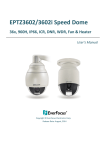
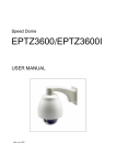
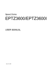
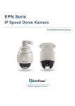
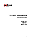
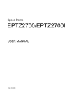
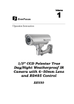
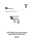
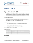
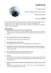
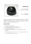
Speed Dome
EPTZ Series
USER MANUAL
Copyright © EverFocus Electronics Corp,
Release Date: Aug, 2013
Analogue IR speed dome series
Table of Contents
EPTZ860 Overview ......................................................................................5
1.1.
Introduction ................................................................................................ 5
1.2.
Specifications ............................................................................................. 6
1.3.
Feature ........................................................................................................ 8
1.4.
Alarm ........................................................................................................... 8
1.5.
EPTZ860 Quick Operation Guide (Work with EKB500) ........................... 9
1.6.
Packing List .............................................................................................. 10
1.7.
Cable Needed............................................................................................ 10
1.8.
Initial Setup ............................................................................................... 11
Address Setting ................................................................................................. 11
Communication Protocol Setting ....................................................................... 15
Transmission Speed Setting (Baud Rate Setting) ............................................. 15
1.9.
Bracket and Speed Dome Installation .................................................... 16
Installation Requirements .................................................................................. 16
EPTZ860 Speed Dome Camera Wall Mount Simple Installation ....................... 17
EPTZ860 Camera Setup Menu ................................................................. 19
1.10.
Structure of the Setup Menu ................................................................... 19
1.11.
System....................................................................................................... 20
1.10.0
<PROTOCOL> ( PELCO-D/P) ............................................................. 21
1.10.1
<COMM> ( 2400.N.8.1)........................................................................ 21
1.10.2
<DOME ID> ( 1 ) .................................................................................. 21
1.10.3
<MODULE> (WX) ................................................................................ 21
1.10.4
<VERSION> ( V3.614P)....................................................................... 21
1.10.5
<COM SET> ........................................................................................ 21
a.
DEVICE ID ( 0000~9999)............................................................................ 21
2
Analogue IR speed dome series
Default value is 1185 ......................................................................................... 21
b.
CHECK ID ( 0000~9999) ............................................................................ 21
Default value is 0 ............................................................................................... 21
c. TARGET ID ................................................................................................. 21
d.
1.12.
BAUD TATE ................................................................................................ 21
Dome ......................................................................................................... 21
1.11.0
PRESET .............................................................................................. 22
1.11.1
SCAN .................................................................................................. 22
1.11.2
GUARD TOURS .................................................................................. 22
1.11.3
PATTERN ............................................................................................ 23
1.11.4
PRIVACY ZONE .................................................................................. 23
1.11.5
OTHER................................................................................................ 23
1.11.6
ALARM ................................................................................................ 25
1.13.
Camera ...................................................................................................... 26
1.14.
IR ................................................................................................................ 26
1.13.0
IR MODE ............................................................................................. 27
1.13.1
OUTPUT POWER (1~9)...................................................................... 27
1.13.2
TESTING TIME (02S ~15S) ................................................................ 27
1.13.3
STANDBY POWER (1~9) .................................................................... 27
1.13.4
STANDBY TIME (15S~30S) ................................................................ 27
1.13.5
ILLUMINATION ON( 00L~25L)............................................................ 27
1.13.6
IR SWITCH ZOOM( 0~20) .................................................................. 27
1.13.7
AMBIENT LIGHT (37L)........................................................................ 27
1.15.
Display....................................................................................................... 28
1.15. Time( DATE/TIME/<SCHEDULE>) ................................................................. 28
1.16. Language ........................................................................................................ 28
3
Analogue IR speed dome series
1.17. Reset ............................................................................................................... 29
1.18. Exit .................................................................................................................. 29
4
Analogue IR speed dome series
EPTZ860 Overview
1.1. Introduction
EPTZ860 is outdoor type, using high sensitivity and high resolution CCD to display high
quality image. The design of ICR (IR cut filter removable) can provide real color even under
strong sunlight in day time. Under slight light in night time, a clear image can still be
displayed. Fast moving function can reach to 360°/1sec. No matter high speed scanning or
low speed scanning, the solid base can avoid vibration. This full-functioned speed dome can
perform best quality images!
* 23X True Day/Night camera module with SONY 1/3" Exview HAD CCD II 960H sensor, 700
TVL resolution
* Auto white balance function creates natural shades of color
* Auto iris adjusts the monitoring image to the best brightness
* Support 360 degree horizontal rotation range and 94 degree tilt rotation range
* Extended IR range of up to 140m/450ft. with high power LEDs
* Intelligent IR function, the IR distance can be adjusted as the lens zooms
* Built-in heater and fan to tolerate low temperature
*Weatherproof IP66 rated to endure all weather conditions
Furthermore, the micro control unit enables camera a nimble and exact movement from
minimal 0.01°/sec to maximal 300°/sec. It can go to every preset position in 1 second. It also
has other advantages such as:
200 preset positions are available.
4 cruise tours can be set, and each tour contains up to 16 positions.
Up to 256 speed domes can be supported on a RS-485 bus when all speed domes
5
Analogue IR speed dome series
are controlled by keyboard EKB500.
Built-in fan to enhance heat dissipation at high temperature and circulate heat to
keep system operation at low temperature.
Built-in 4 alarm inputs and 2 alarm outputs.
All of the features make the intelligent high-speed dome camera works for a wide range and
demanding application such as banks, airports, stations, casinos, streets of cities, intelligent
buildings, etc.
1.2. Specifications
Product Model
EPTZ860
Pickup Device
1/3"SONY 960H CCD
Scanning System
NTSC or PAL
Min.Illumination
Color 0.2 LUX, B/W 0.01 LUX,0LUX(IR LED On)
S/N Ratio(AGC OFF)
≥52dB
Electronic Shutter
Optical Zoom
Auto/1/50—1/10,000SEC
23X Optical Zoom(F=1.4 f=3.9~89.7mm)
Auto Iris
Streaming Frame Rate
Auto
1~30fps(NTSC),1~25Ffps(PAL)
Focus Control
Auto/Manual
True Day/Night
Auto
Auto Gain Control
Rang Adjustable
Backlight Comp.
(NO/OFF)/(HSBLC)
White Balance
Auto/Auto tracking/Indoor/Outdoor/Manual module
Video Output
1.0Vp-p, (75Ω Composite video )
Manual Pan/Tilt Speed
Pan:0.01°~180°/S,Tilt:0.01°~180°/S
Position Accuracy
±0.1°
Horizontal Rotation Range
360°Unlimited rotation
6
Analogue IR speed dome series
Tilt Rotation Range
94°Pendulum motion
Auto Speed Control
control speed auto-adjusted according to zoom length changing
Auto Pan Speed
300°/s
Dwell Time at Preset Position
0.5-10S,4 groups
Tour
4 groups
Tour Point Per Group
16Preset positions
Pattern
4PCS
Communication
RS485 Bus
Communication Protocol
EVF-1,Pelco-D, Pelco-P
Baud Rate
Alarm
1200/2400/4800/9600bps
4 inputs and 2 outputs (Optional)
Environmental Rating
IP66 for outdoor
IR Testing Time
2-15s selectable
IR Illumination Distance
140M
Power Source
24VAC
Power Consumption
25w max
Operating Temperature
Dimensions(W+H)
Weight
Outdoor: -40°~ +60°
337.7×340.9mm/13.3"×13.4"
With Bracket 7.2kg,w/o bracket 6.6kg
Certificates
CE,FCC
7
Analogue IR speed dome series
1.3. Feature
Profile of EPTZ860
1.4. Alarm
Function direction list:
Pin #
Function
1
ALMIN1 (Alarm Input 1)
2
ALMIN2 (Alarm Input 2)
3
ALMIN3 (Alarm Input 3)
4
ALMIN4 (Alarm Input 4)
5
GND (Alarm input Common)
6
ALARM NC OUT (Alarm Output Normal Close )
7
ALARM OUT COM (Alarm Output Common )
8
ALARM NO OUT (Alarm Output Normal Open)
8
Analogue IR speed dome series
Label as below :
1.5. EPTZ860 Quick Operation Guide (Work with EKB500)
EPTZ860 and EKB500 (Keyboard) can work together by using factory default setting. You just
need to connect cables by the following steps:
1. Connect the RS-485 cable to EPTZ860 and a keyboard (EKB500).
2. Connect a video cable from EPTZ860 to a monitor.
3. Connect the power to the EPTZ860 and a keyboard (EKB500).
After the EPTZ860 finishes the self-test mode, you can start to operate the EPTZ860 via the
keyboard.
To operate the EPTZ860:
UP
IRIS
+
Focus
F.
Zoom
In
Zoom OUT
Zoom IN
LEFT
-
N.
RIGHT
Out
DOWN
9
Analogue IR speed dome series
1. Shift the Joystick up/down or right/left to view from camera.
2. Turn the top of the Joystick to zoom in/out.
3. Press Zoom In/Out, Focus F. /N. and IRIS +/- function keys to operate the EPTZ860.
1.6. Packing List
There are main body with a camera module, housing with a base board, bracket, power adapter,
Manual, plus one tool packet in the package. The detail accessories are listed below:
Standard
Camera Main Body x1
Bracket x1
Housing x1
Tool packet
RS485 Terminal Block
1 desiccant packs
1.7. Cable Needed
Power Cable
Power source with 24VAC/25W max.provides the power to the EPTZ860. An extension power line
may be needed.
Note: The input AC voltage range of an adapter depends on different area.
Please make sure the voltage range before installing.
10
Analogue IR speed dome series
Video Cable
A BNC cable is used for connecting an EPTZ860 to a DVR or a monitor. An amplifier may be
needed if the video cable is too long.
RS485 Cable
Yellow wire represents RS485+, orange wire represents RS485-. Connect RS485 to EKB500 and
you will be able to control the speed dome by a keyboard. If you are unable to control the speed
dome with EKB500, it is probably due to a mis-connection. Please try to switch RS485 wires and
connect again.
1.8. Initial Setup
Initial setup includes dome address, communication protocol, transmission speed, and terminal
resistance settings. All of the settings should be confirmed before the dome is installed. The
control-related setting that is address, communication protocol and transmission speed have to
be set consistently with the control device such as a keyboard or a DVR.
Notice: Please make sure the power is off before setting, and restart the EPTZ860 to enable a
new value after changing.
Address Setting
The address code of the EPTZ860 should be set to correspond properly with a control device
to control multiple dome cameras. The address codes are made up by the dip switch on the
camera main body. The 8 bits dip switch indicates the binary coded of the address, and there
are 256 addresses can be selected (0 ~ 255). It also means that there are up to 256 dome
cameras that can cascade on the RS-485 bus. The dip switch setting and the indicated address
are represented in the following diagram.
11
Analogue IR speed dome series
Note: The factory default address is 1.
Notice: Please make sure the power is off before setting, and restart the EPTZ860 to enable a
new value after changing.
Note: You will see the label of Protocol & Baud Rate as well as RS-485 ID address show on the
speed dome. White part represents the switch key. For example: for EVF protocol, white keys are
all switched downward; for ID Address 0, white keys are all switched downward.
Settings of SW2
The 1st-3rd DIP Switch are for reserved .The 4th and 5th DIP set the Baud rate, factory-default
setting is 2400bps(Baud rate: 1200bps, 2400bps, 4800bps, 9600bps selectable)
The 8th bit of DIP switch SW2 is to select the matching resistor.
12
Analogue IR speed dome series
Switch
Address
ON
1
2
3
4
5
6
7
8
ON
1
2
3
4
5
6
7
8
2
3
4
5
6
7
8
2
3
4
5
6
7
8
ON
1
ON
1
ON
1
2
3
4
5
6
7
8
2
3
4
5
6
7
8
2
3
4
5
6
7
8
ON
1
ON
1
ON
1
2
3
4
5
6
7
8
ON
1
2
3
4
5
6
7
8
2
3
4
5
6
7
8
ON
1
ON
1
2
3
4
5
6
7
8
ON
1
2
3
4
5
6
7
8
2
3
4
5
6
7
8
ON
1
ON
1
2
3
4
5
6
7
8
ON
1
2
3
4
5
6
7
8
2
3
4
5
6
7
8
2
3
4
5
6
7
8
ON
1
ON
1
ON
1
2
3
4
5
6
7
8
2
3
4
5
6
7
8
2
3
4
5
6
7
8
ON
1
ON
1
ON
1
2
3
4
5
6
7
8
ON
1
2
3
4
5
6
7
8
2
3
4
5
6
7
8
ON
1
ON
1
2
3
4
5
6
7
8
ON
1
2
3
4
5
6
7
8
2
3
4
5
6
7
8
ON
1
ON
1
2
3
4
5
6
7
8
ON
1
2
3
4
5
6
7
8
2
3
4
5
6
7
8
ON
1
ON
1
2
3
4
5
6
7
8
ON
1
2
3
4
5
6
7
8
2
3
4
5
6
7
8
ON
1
0
1
2
3
4
5
6
7
8
9
10
11
12
13
14
15
16
17
18
19
20
21
22
23
24
25
26
27
28
29
30
31
Switch
Address
ON
1
2
3
4
5
6
7
8
ON
1
2
3
4
5
6
7
8
2
3
4
5
6
7
8
2
3
4
5
6
7
8
ON
1
ON
1
ON
1
2
3
4
5
6
7
8
2
3
4
5
6
7
8
2
3
4
5
6
7
8
ON
1
ON
1
ON
1
2
3
4
5
6
7
8
ON
1
2
3
4
5
6
7
8
2
3
4
5
6
7
8
ON
1
ON
1
2
3
4
5
6
7
8
ON
1
2
3
4
5
6
7
8
2
3
4
5
6
7
8
ON
1
ON
1
2
3
4
5
6
7
8
ON
1
2
3
4
5
6
7
8
2
3
4
5
6
7
8
2
3
4
5
6
7
8
ON
1
ON
1
ON
1
2
3
4
5
6
7
8
2
3
4
5
6
7
8
2
3
4
5
6
7
8
ON
1
ON
1
ON
1
2
3
4
5
6
7
8
ON
1
2
3
4
5
6
7
8
2
3
4
5
6
7
8
ON
1
ON
1
2
3
4
5
6
7
8
ON
1
2
3
4
5
6
7
8
2
3
4
5
6
7
8
ON
1
ON
1
2
3
4
5
6
7
8
ON
1
2
3
4
5
6
7
8
2
3
4
5
6
7
8
ON
1
ON
1
2
3
4
5
6
7
8
ON
1
2
3
4
5
6
7
8
2
3
4
5
6
7
8
ON
1
32
33
34
35
36
37
38
39
40
41
42
43
44
45
46
47
48
49
50
51
52
53
54
55
56
57
58
59
60
61
62
63
Switch
Address
ON
1
2
3
4
5
6
7
8
ON
1
2
3
4
5
6
7
8
2
3
4
5
6
7
8
2
3
4
5
6
7
8
ON
1
ON
1
ON
1
2
3
4
5
6
7
8
2
3
4
5
6
7
8
2
3
4
5
6
7
8
ON
1
ON
1
ON
1
2
3
4
5
6
7
8
ON
1
2
3
4
5
6
7
8
2
3
4
5
6
7
8
ON
1
ON
1
2
3
4
5
6
7
8
ON
1
2
3
4
5
6
7
8
2
3
4
5
6
7
8
ON
1
ON
1
2
3
4
5
6
7
8
ON
1
2
3
4
5
6
7
8
2
3
4
5
6
7
8
2
3
4
5
6
7
8
ON
1
ON
1
ON
1
2
3
4
5
6
7
8
2
3
4
5
6
7
8
2
3
4
5
6
7
8
ON
1
ON
1
ON
1
2
3
4
5
6
7
8
ON
1
2
3
4
5
6
7
8
2
3
4
5
6
7
8
ON
1
ON
1
2
3
4
5
6
7
8
ON
1
2
3
4
5
6
7
8
2
3
4
5
6
7
8
ON
1
ON
1
2
3
4
5
6
7
8
ON
1
2
3
4
5
6
7
8
2
3
4
5
6
7
8
ON
1
ON
1
2
3
4
5
6
7
8
ON
1
2
3
4
5
6
7
8
2
3
4
5
6
7
8
ON
1
13
64
65
66
67
68
69
70
71
72
73
74
75
76
77
78
79
80
81
82
83
84
85
86
87
88
89
90
91
92
93
94
95
Switch
Address
ON
1
2
3
4
5
6
7
8
2
3
4
5
6
7
8
2
3
4
5
6
7
8
2
3
4
5
6
7
8
2
3
4
5
6
7
8
2
3
4
5
6
7
8
2
3
4
5
6
7
8
2
3
4
5
6
7
8
2
3
4
5
6
7
8
2
3
4
5
6
7
8
2
3
4
5
6
7
8
2
3
4
5
6
7
8
2
3
4
5
6
7
8
2
3
4
5
6
7
8
2
3
4
5
6
7
8
2
3
4
5
6
7
8
2
3
4
5
6
7
8
2
3
4
5
6
7
8
2
3
4
5
6
7
8
2
3
4
5
6
7
8
2
3
4
5
6
7
8
2
3
4
5
6
7
8
2
3
4
5
6
7
8
2
3
4
5
6
7
8
2
3
4
5
6
7
8
2
3
4
5
6
7
8
2
3
4
5
6
7
8
2
3
4
5
6
7
8
2
3
4
5
6
7
8
2
3
4
5
6
7
8
2
3
4
5
6
7
8
2
3
4
5
6
7
8
ON
1
ON
1
ON
1
ON
1
ON
1
ON
1
ON
1
ON
1
ON
1
ON
1
ON
1
ON
1
ON
1
ON
1
ON
1
ON
1
ON
1
ON
1
ON
1
ON
1
ON
1
ON
1
ON
1
ON
1
ON
1
ON
1
ON
1
ON
1
ON
1
ON
1
ON
1
96
97
98
99
100
101
102
103
104
105
106
107
108
109
110
111
112
113
114
115
116
117
118
119
120
121
122
123
124
125
126
127
Analogue IR speed dome series
Switch
Address
ON
1
2
3
4
5
6
7
8
ON
1
2
3
4
5
6
7
8
2
3
4
5
6
7
8
ON
1
ON
1
2
3
4
5
6
7
8
ON
1
2
3
4
5
6
7
8
2
3
4
5
6
7
8
ON
1
ON
1
2
3
4
5
6
7
8
2
3
4
5
6
7
8
2
3
4
5
6
7
8
ON
1
ON
1
ON
1
2
3
4
5
6
7
8
2
3
4
5
6
7
8
ON
1
ON
1
2
3
4
5
6
7
8
ON
1
2
3
4
5
6
7
8
2
3
4
5
6
7
8
ON
1
ON
1
2
3
4
5
6
7
8
2
3
4
5
6
7
8
2
3
4
5
6
7
8
ON
1
ON
1
ON
1
2
3
4
5
6
7
8
2
3
4
5
6
7
8
2
3
4
5
6
7
8
ON
1
ON
1
ON
1
2
3
4
5
6
7
8
2
3
4
5
6
7
8
ON
1
ON
1
2
3
4
5
6
7
8
ON
1
2
3
4
5
6
7
8
2
3
4
5
6
7
8
ON
1
ON
1
2
3
4
5
6
7
8
2
3
4
5
6
7
8
2
3
4
5
6
7
8
ON
1
ON
1
ON
1
2
3
4
5
6
7
8
2
3
4
5
6
7
8
ON
1
ON
1
2
3
4
5
6
7
8
ON
1
2
3
4
5
6
7
8
128
129
130
131
132
133
134
135
136
137
138
139
140
141
142
143
144
145
146
147
148
149
150
151
152
153
154
155
156
157
158
159
Switch
Address
ON
1
2
3
4
5
6
7
8
ON
1
2
3
4
5
6
7
8
2
3
4
5
6
7
8
ON
1
ON
1
2
3
4
5
6
7
8
ON
1
2
3
4
5
6
7
8
2
3
4
5
6
7
8
ON
1
ON
1
2
3
4
5
6
7
8
2
3
4
5
6
7
8
2
3
4
5
6
7
8
ON
1
ON
1
ON
1
2
3
4
5
6
7
8
2
3
4
5
6
7
8
ON
1
ON
1
2
3
4
5
6
7
8
ON
1
2
3
4
5
6
7
8
2
3
4
5
6
7
8
ON
1
ON
1
2
3
4
5
6
7
8
2
3
4
5
6
7
8
2
3
4
5
6
7
8
ON
1
ON
1
ON
1
2
3
4
5
6
7
8
2
3
4
5
6
7
8
2
3
4
5
6
7
8
ON
1
ON
1
ON
1
2
3
4
5
6
7
8
2
3
4
5
6
7
8
ON
1
ON
1
2
3
4
5
6
7
8
ON
1
2
3
4
5
6
7
8
2
3
4
5
6
7
8
ON
1
ON
1
2
3
4
5
6
7
8
2
3
4
5
6
7
8
2
3
4
5
6
7
8
ON
1
ON
1
ON
1
2
3
4
5
6
7
8
2
3
4
5
6
7
8
ON
1
ON
1
2
3
4
5
6
7
8
ON
1
2
3
4
5
6
7
8
160
161
162
163
164
165
166
167
168
169
170
171
172
173
174
175
176
177
178
179
180
181
182
183
184
185
186
187
188
189
190
191
Switch
Address
ON
1
2
3
4
5
6
7
8
ON
1
2
3
4
5
6
7
8
2
3
4
5
6
7
8
ON
1
ON
1
2
3
4
5
6
7
8
ON
1
2
3
4
5
6
7
8
2
3
4
5
6
7
8
ON
1
ON
1
2
3
4
5
6
7
8
2
3
4
5
6
7
8
2
3
4
5
6
7
8
ON
1
ON
1
ON
1
2
3
4
5
6
7
8
2
3
4
5
6
7
8
ON
1
ON
1
2
3
4
5
6
7
8
ON
1
2
3
4
5
6
7
8
2
3
4
5
6
7
8
ON
1
ON
1
2
3
4
5
6
7
8
2
3
4
5
6
7
8
2
3
4
5
6
7
8
ON
1
ON
1
ON
1
2
3
4
5
6
7
8
2
3
4
5
6
7
8
2
3
4
5
6
7
8
ON
1
ON
1
ON
1
2
3
4
5
6
7
8
2
3
4
5
6
7
8
ON
1
ON
1
2
3
4
5
6
7
8
ON
1
2
3
4
5
6
7
8
2
3
4
5
6
7
8
ON
1
ON
1
2
3
4
5
6
7
8
2
3
4
5
6
7
8
2
3
4
5
6
7
8
ON
1
ON
1
ON
1
2
3
4
5
6
7
8
2
3
4
5
6
7
8
ON
1
ON
1
2
3
4
5
6
7
8
ON
1
14
2
3
4
5
6
7
8
192
193
194
195
196
197
198
199
200
201
202
203
204
205
206
207
208
209
210
211
212
213
214
215
216
217
218
219
220
221
222
223
Switch
Address
ON
1
2
3
4
5
6
7
8
2
3
4
5
6
7
8
2
3
4
5
6
7
8
2
3
4
5
6
7
8
2
3
4
5
6
7
8
2
3
4
5
6
7
8
2
3
4
5
6
7
8
2
3
4
5
6
7
8
2
3
4
5
6
7
8
2
3
4
5
6
7
8
2
3
4
5
6
7
8
2
3
4
5
6
7
8
2
3
4
5
6
7
8
2
3
4
5
6
7
8
2
3
4
5
6
7
8
2
3
4
5
6
7
8
2
3
4
5
6
7
8
2
3
4
5
6
7
8
2
3
4
5
6
7
8
2
3
4
5
6
7
8
2
3
4
5
6
7
8
2
3
4
5
6
7
8
2
3
4
5
6
7
8
2
3
4
5
6
7
8
2
3
4
5
6
7
8
2
3
4
5
6
7
8
2
3
4
5
6
7
8
2
3
4
5
6
7
8
2
3
4
5
6
7
8
2
3
4
5
6
7
8
2
3
4
5
6
7
8
2
3
4
5
6
7
8
ON
1
ON
1
ON
1
ON
1
ON
1
ON
1
ON
1
ON
1
ON
1
ON
1
ON
1
ON
1
ON
1
ON
1
ON
1
ON
1
ON
1
ON
1
ON
1
ON
1
ON
1
ON
1
ON
1
ON
1
ON
1
ON
1
ON
1
ON
1
ON
1
ON
1
ON
1
224
225
226
227
228
229
230
231
232
233
234
235
236
237
238
239
240
241
242
243
244
245
246
247
248
249
250
251
252
253
254
255
Analogue IR speed dome series
Communication Protocol Setting
The 1st, 2nd and 3rd bits are used to set communication protocol. The factory default protocol is
EVF.
Notice: Please make sure the power is off before setting, and restart the EPTZ860 to enable a
new value after changing.
Set all of protocol switches to ON; the speed dome EPTZ860 will enter a self-test mode.
Transmission Speed Setting (Baud Rate Setting)
The 4th and 5th bits on the PCB board are used to set the Baud Rate. The default baud rate setting
is 9600.
SW2
4800 BPS
2400 BPS
1200 BPS
2
2
3
3
4
4
5
5
6
6
7
7
8
8
8
8
7
8
7
6
7
6
5
6
5
4
5
4
3
4
3
2
3
2
2
Baud Rate
Terminal
Resistance
Notice: Please make sure the power is off before setting, and restart the EPTZ860 to enable a
new value after changing.
15
ON
1
ON
1
ON
1
ON
1
ON
1
Protocol
9600 BPS
Analogue IR speed dome series
1.9. Bracket and Speed Dome Installation
Installation Requirements
1. Installation should be handled by a qualified service agent and should comply with all
local regulations. Service personnel should expect potential problems such as surface
strength, surface material, falling objects, outer breaches, building vibration or other
similar conditions.
2. Check for all necessary materials, and ensure if the selected installation location is
suitable for the EPTZ860.
EPTZ860 overview
16
Analogue IR speed dome series
EPTZ860 Speed Dome Camera Wall Mount Simple Installation
1. Screw the top housing to bracket by using a hexagon wrench.
2. Put the waterproof silicon pad on top of the bracket base for waterproof purpose.
Waterproof silicon pad
Bracket base
3. Connect the cable you detached from base board to the RS485 cable, Power cable and video
cable you thread from the wall or ceiling. RS485 cable has to be connected via a terminal block. If
you need to connect alarm cable, thread the alarm cable through the second hole.
Note: Since
video cable and power cable are bare wires, installers have to prepare their own BNC connector
and power cord connector.
17
Analogue IR speed dome series
4. Screw in 4 screws for mounting the bracket base.
5. Screw in 4 long screws to fix the bracket to bracket base.
Note : The camera module on the mechanical part is very sensitive. Please be careful when
installing this part.
6. Turn on the power, and start to operate the EPTZ860.
18
Analogue IR speed dome series
Note: When turning on the power, EPTZ860 will enter self-inspection mode, and carry out a
self-testing program. After finishing self-inspection, you can start to operate the EPTZ860.
EPTZ860 Camera Setup Menu
In this section, setup and operation guide of EPTZ860 will be introduced. There are 9 items of the
setting menu.
1.10. Structure of the Setup Menu
Press MENU to enter camera setup menu.
Turn the Joystick up/down to change subentries, and right/left to change the setting. If there is an
arrow at the end of selection, it means that selection has a sub-menu, please press Enter key of
keyboard to enter sub-menu.
19
Analogue IR speed dome series
<SYSTEM>
<DOME>
<CAMERA>
<IR>
<DISPLAY>
<TIME>
<LANGUAGE>
<RESET>
EXIT
(diagram 3.1)
1.11. System
In main menu, turn joystick Up / Down to select SYSTEM option. Turn joystick Left / Right to enter
SYSTEM sub-menu (see diagram 3.2).
<PROTOCOL >
<SYSTEM>
<COMM>
<DOME>
PELCO-D/P
2400.N.8.1
<DOME ID>
<CAMERA>
<IR>
<DISPLAY>
1
<MODULE>
WX
<VERSION >
V3.614P
<COMM SET>
<TIME>
EXIT
<LANGUAGE>
<RESET>
EXIT
(diagram 3.2)
Turn joystick Left / Right to enter COMM SET sub-menu (see diagram 3.3).
<PROTOCOL >
<COMM>
PELCO-D/P
2400.N.8.1
<DOME ID>
1
<MODULE>
WX
<VERSION >
V3.614P
DEVICE ID
0000~9999
CHECK ID
0000~9999
TARGET ID
BAUD TATE
EXIT
<COMM SET>
EXIT
(diagram 3.3)
20
Analogue IR speed dome series
1.10.0
<PROTOCOL> ( PELCO-D/P)
1.10.1
<COMM> ( 2400.N.8.1)
1.10.2
<DOME ID> ( 1 )
1.10.3
<MODULE> (WX)
1.10.4
<VERSION> ( V3.614P)
1.10.5
<COM SET>
a. DEVICE ID ( 0000~9999)
Default value is 1185
b. CHECK ID ( 0000~9999)
Default value is 0
c. TARGET ID
d. BAUD TATE
1.12. Dome
In main menu, turn joystick Up or Down to select DOME option. Press Enter key or turn joystick
Left / Right to enter DOME sub-menu (See diagram 3.4).
<SYSTEM>
<PRESET>
<DOME>
<SCAN>
<CAMERA>
<GUARD TOURS>
<IR>
<PATTERN>
<DISPLAY>
<PRIVACY ZONE>
<TIME>
<OTHER>
<LANGUAGE>
<ALARM>
<RESET>
EXIT
EXIT
(diagram 3.4)
21
Analogue IR speed dome series
1.11.0 PRESET
a
PRESET NO.001 ( The default is PRESET NO.001)
b
CALL PRESET
C
SET PRESET
Press Enter key of keyboard to enter PRESET sub-menu.
<PRESET>
<SCAN>
PRESET NO.001
<GUARD TOURS>
CALL PRESET
<PATTERN>
SET PRESET
<PRIVACY ZONE>
EXIT
<OTHER>
<ALARM>
EXIT
(diagram 3.5)
1.11.1 SCAN
1.11.2 GUARD TOURS
a
GUARD TOUR NO.1
b
CALL GUARD TOUR
C
GUARD TOUR
Press Enter key of keyboard to enter GUARD TOURS sub-menu.
<PRESET>
<SCAN>
PRESET
GUARD
TOUR NO.1
<GUARD TOURS>
PRESET
NO.001
CALL
GUARD
TOUR
<PATTERN>
CALL PRESET
<GUARD
TOUR>
<PRIVACY ZONE>
SET PRESET
EXIT
<OTHER>
<ALARM>
EXIT
(diagram 3.6)
22
Analogue IR speed dome series
1.11.3 PATTERN
a
PATTERN NO.1
b
CALL PATTERN
C
PATTERN
Press Enter key of keyboard to enter PATTERN sub-menu.
<PRESET>
<SCAN>
PRESETNO.1
PATTERN
<GUARD TOURS>
PRESET
NO.001
CALL
PATTERN
<PATTERN>
CALL PRESET
<PATTERN>
<PRIVACY ZONE>
SET PRESET
EXIT
<OTHER>
<ALARM>
EXIT
(diagram 3.7)
1.11.4 PRIVACY ZONE
1.11.5 OTHER
Press Enter key of keyboard to enter OHTER sub-menu.
<PRESET>
<SCAN>
PRESET
PARK
MODE
<GUARD TOURS>
PRESET
NO.001
PARK
TIME
<PATTERN>
CALL PRESET
POWER
ON ACT
<PRIVACY ZONE>
SET PRESET
RATIO
SPEED
<OTHER>
AUTO FLIP
<ALARM>
EXIT
EXIT
(diagram 3.8)
a
PARK MODE ( NONE/ PATTERN 1/ TOUR 1/ 360SCAN/ AB SCAN/ PRESET 1~PRESET 8)
23
Analogue IR speed dome series
Press Enter key of keyboard to enter PARK MODE sub-menu.
NONE
PARK MODE
PATTERN1
PARK TIME
TOUR1
POWER
360SCAN
ON ACT
RATIO SPEED
AB SCAN
AUTO FLIP
PRESET1~PRESET8
EXIT
EXIT
(diagram 3.9)
b
PARK TIME (1 ~ 60)
The default is 5
C
POWER ON ACT
MEMORY (The default is MEMORY)/ PATTERN 1/ TOUR 1/ 360SCAN/ AB SCAN/ PRESET 1~PRESET 8
Press Enter key of keyboard to enter POWER ON ACT sub-menu.
MEMORY
PARK MODE
PATTERN1
PARK TIME
TOUR1
POWER ON
ACT
The default is
360SCAN
RATIO SPEED
AB SCAN
AUTO FLIP
PRESET1~PRESET8
EXIT
EXIT
(diagram 4.0)
d
RATIO SPEED ( ON/ OFF)
The default is ON
Press Enter key of keyboard to enter RATIO SPEED sub-menu.
24
MEMORY
Analogue IR speed dome series
PARK MODE
ON
The default is ON
PARK TIME
OFF
The default is ON
POWER ON
EXIT
ACT
RATIO SPEED
AUTO FLIP
EXIT
(diagram 4.1)
e
AUTO FLIP ( ON/ OFF)
The default is ON
Press Enter key of keyboard to enter AUTO FLIP sub-menu.
PARK MODE
PARK TIME
ON
The default is ON
OFF
The default is ON
EXIT
POWER ON
ACT
RATIO SPEED
AUTO FLIP
EXIT
(diagram 4.2)
1.11.6
ALARM
Press Enter key of keyboard to enter ALARM sub-menu.
<PRESET>
ALARM IN
ON/OFF
<SCAN>
ALARM OUT
NC/NO
<GUARD TOURS>
PATROL TIME
0.5S~10S
<PATTERN>
ALARM1
PR BIG/ PRESET1~PRESET16
<PRIVACY ZONE>
ALARM2
PR LOW/ PRESET1~PRESET16
<OTHER>
ALARM3
<ALARM>
ALARM4
EXIT
EXIT
(diagram 4.3)
25
refer to below point f
PR OFF/ PRESET1~PRESET16
Analogue IR speed dome series
a
ALARM IN ( ON/ OFF)
b
ALARM IN ( NC/ NO)
C
PATROL TIME ( 05S~10S)
d
ALARM 1 ( PR BIG/ PRESET 1~ PRESET 16)
e
ALARM 2 ( PR LOW/ PRESET 1 ~ PRESET 16)
f
ALARM 3
Turn joystick up ( PRESET 21/ PRESET43/ PRESET 65/ PRESET 87/ PRESET 109/ PRESET 121/ PRESET 43/
PRESET 65)
Turn joystick down ( PRESET 1~ PRESET 16)
g ALARM 4 ( PR OFF/ PRESET 1~ PRESET 16)
1.13. Camera
1.14. IR
In main menu, turn joystick Up or Down to select IR option. Press Enter key or turn joystick Left /
Right to enter IR sub-menu (See diagram 4.4).
<SYSTEM>
IR MODE
<DOME>
OUTPUT POWER
<CAMERA>
TESTING TIME
02S~15S
<IR>
STANDBY POWER
1~9
<DISPLAY>
STANDBY TIME
<TIME>
ILLUMINATION ON
<LANGUAGE>
IR SWITCH ZOOM
<RESET>
AMBIENT LIGHT
EXIT
EXIT
(diagram 4.4)
26
AUTO/LARGE LIGHT/SMALL LIGHT/MANUAL/OFF
1~9
15S~30S
00L~25L
0~20
37L
Analogue IR speed dome series
1.13.0 IR MODE
a AUTO
b
LARGE LIGHT
C
SMALL LIGHT
d MANUAL
e
OFF
Press Enter key of keyboard to enter IR MODE sub-menu.
IR MODE
OUTPUT POWER
AUTO
TESTING TIME
LARGE LIGHT
STANDBY POWER
SMALL LIGHT
STANDBY TIME
MANUAL
ILLUMINATION ON
OFF
IR SWITCH ZOOM
EXIT
AMBIENT LIGHT
EXIT
(diagram 4.5)
1.13.1 OUTPUT POWER (1~9)
1.13.2 TESTING TIME (02S ~15S)
1.13.3 STANDBY POWER (1~9)
1.13.4 STANDBY TIME (15S~30S)
1.13.5 ILLUMINATION ON( 00L~25L)
1.13.6 IR SWITCH ZOOM( 0~20)
1.13.7 AMBIENT LIGHT (37L)
27
Analogue IR speed dome series
1.15. Display
In main menu, turn joystick Up or Down to select DISPLAY option. Press Enter key or turn joystick
Left / Right to enter DISPLAY sub-menu (See diagram 4.6).
<SYSTEM>
DOME ID
ON/OFF
<DOME>
ZOOM
ON/OFF
<CAMERA>
P AND T
ON/OFF
<IR>
ACT
ON/OFF
<DISPLAY>
TIME
ON/OFF
<TIME>
IR
ON/OFF
<LANGUAGE>
EXIT
<RESET>
EXIT
(diagram 4.6)
1.14.0
DOME ID (ON/ OFF)
1.14.1
ZOOM (ON/ OFF)
1.14.2
P AND T (ON/ OFF)
1.14.3
ACT (ON/ OFF)
1.14.4
TIME (ON/ OFF)
1.14.5
IR (ON/ OFF)
1.15. Time( DATE/TIME/<SCHEDULE>)
1.16. Language
In main menu, turn joystick Up or Down to select LAGUAGE option. Press Enter key or turn
joystick Left / Right to enter LANGUAGE sub-menu (See diagram 4.7).
28
Analogue IR speed dome series
<SYSTEM>
ENGLISH
<DOME>
PORTUGUESE
<CAMERA>
FRENCH
<IR>
GERMAN
<DISPLAY>
ITALIAN
<TIME>
SPANISH
<LANGUAGE>
EXIT
<RESET>
EXIT
(diagram 4.7)
1.17. Reset
In main menu, turn joystick Up or Down to select RESET option. Press Enter key or turn joystick
Left / Right to enter RESET sub-menu (See diagram 4.8).
<SYSTEM>
<DOME>
CAM DATA
<CAMERA>
SYS DATA
<IR>
FACTORY DEFAULT
<DISPLAY>
CALIBRATION
<TIME>
EXIT
<LANGUAGE>
<RESET>
EXIT
(diagram 4.8)
1.17.0
CAM DATA
1.17.1
SYS DATA
1.17.2
FACTORY DEFAULT
1.17.3
CALIBRATION
a. Off
b. 1D~15D, the default is 15D
1.18. Exit
Select Exit to save settings and exit from current page.
29
OFF/ 1D ~59D
The default is 15D
Analogue IR speed dome series
EverFocus Electronics Corp.
Head Office:
Europe Office:
12F, No.79 Sec. 1 Shin-Tai Wu Road,
Hsi-Chih, Taipei, Taiwan
TEL: +886-2-26982334
FAX: +886-2-26982380
www.everfocus.com.tw
Albert-Einstein-Strasse 1
D-46446 Emmerich, Germany
TEL: +49(0)-2822-9394-0
FAX: +49(0)-2822-9394-95
www.everfocus.de
USA L.A. Office:
China Office:
1801 Highland Ave. Unit A
Room B-05D-1, KESHI PLAZA, Shangdi
Information Industry Base,
Haidian District, Beijing China
100085
TEL: +86-10-62973336/37/38/39
FAX: +86-10-62971423
Duarte, CA 91010, U.S.A.
TEL: +1-626-844-8888
FAX: +1-626-844-8838
www.everfocus.com
www.everfocus.com.cn
USA N.Y. Office:
Japan Office:
415 Oser Avenue Unit S
Hauppauge, NY 11788
1809 WBG MARIBU East 18F,
2-6 Nakase.Mihama-ku.
Chiba city 261-7118, Japan
TEL: +81-43-212-8188
FAX: +81-43-297-0081
TEL: +1-631-436-5070
FAX: +1-631-436-5027
www.everfocus.com
www.everfocus.co.jp
Your EverFocus product is designed and
manufactured with high quality materials and
components which can be recycled and reused.
This symbol means that electrical and electronic
equipment, at their end-of-life, should be
disposed of separately from your household
waste.
Please, dispose of this equipment at your local
community waste collection/recycling centre.
In the European Union there are separate
collection systems for used electrical and
electronic product.
Please, help us to conserve the environment we
live in!
Ihr EverFocus Produkt wurde entwickelt und
hergestellt mit qualitativ hochwertigen
Materialien und Komponenten, die recycelt und
wieder verwendet werden können.
Dieses Symbol bedeutet, dass elektrische und
elektronische Geräte am Ende ihrer
Nutzungsdauer vom Hausmüll getrennt entsorgt
werden sollen.
Bitte entsorgen Sie dieses Gerät bei Ihrer
örtlichen kommunalen Sammelstelle oder im
Recycling Centre.
Helfen Sie uns bitte, die Umwelt zu erhalten, in
der wir leben!
30