1
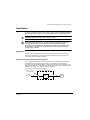
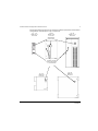
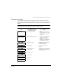
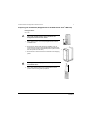
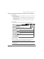
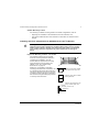
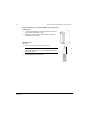
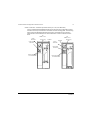
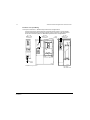
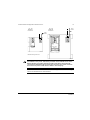
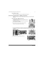
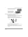
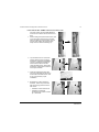
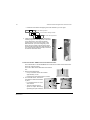
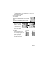
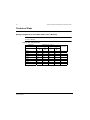
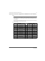
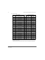
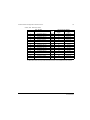
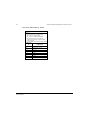
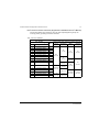
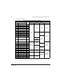
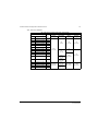
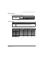
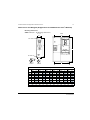
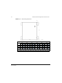
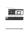
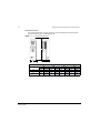
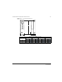
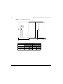
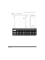
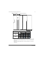
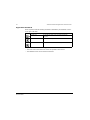
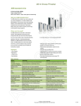
User’s Manual
ACS550-PC/PD Packaged Drive with Disconnect
Supplement to ACS550-01/U1 User’s Manual
ii
ACS550 Drive Manuals
GENERAL MANUALS
ACS550-U1 User's Manual (1…150 HP)
• Safety
• Installation
• Start-Up
• Embedded Fieldbus
• Fieldbus Adapter
• Diagnostics
• Maintenance
• Technical Data
ACS550 Technical Reference Manual
(available in electronic format only)
• Detailed Product Description
• Practical Engineering Guides
ACS550-PC/PD Packaged Drive with Disconnect
Supplement for ACS550-01/U1 User’s Manual
• Safety
• Installation
• Start-Up
• Maintenance
• Technical Data
ACS550- CC/CF Packaged Drive with Bypass
Supplement for ACS550-01/U1 User’s Manual
• Safety
• Installation
• Start-Up
• Maintenance
• Technical Data
© 2005 ABB Inc. All Rights Reserved.
ACS550-PC/PD Packaged Drive with Disconnect
ACS550-PC/PD Packaged Drive with Disconnect
1
Safety
WARNING! The ACS550 adjustable speed AC drive with Input Disconnect
should ONLY be installed by a qualified electrician.
WARNING! Even when the motor is stopped, dangerous voltage is present at
the Power Circuit terminals U1, V1, W1 and U2, V2, W2 and, depending on the
frame size, UDC+ and UDC-, or BRK+ and BRK-.
WARNING! Dangerous voltage is present when input power is connected.
After disconnecting the supply, wait at least 5 minutes (to let the intermediate
circuit capacitors discharge) before removing the cover.
WARNING! Even when power is removed from the input terminals of the
ACS550, there may be dangerous voltage (from external sources) on the
terminals of the relay outputs.
WARNING! When the control terminals of two or more drive units are
connected in parallel, the auxiliary voltage for these control connections must
be taken from a single source which can either be one of the units or an
external supply.
WARNING! The ACS550 will start up automatically after an input voltage
interruption if the external run command is on.
WARNING! When the ACS550 with Input Disconnect is connected to the line
power, the Motor Terminals T1, T2, and T3 are live even if the motor is not
running. Do not make any connections when the ACS550 with Input
Disconnect is connected to the line. Disconnect and lock out power to the
drive before servicing the drive. Failure to disconnect power may cause
serious injury or death.
Note! For more technical information, contact the factory or your local ABB sales
representative.
Use of Warnings and Notes
There are two types of safety instructions throughout this manual:
• Notes draw attention to a particular condition or fact, or give information on a
subject.
• Warnings caution you about conditions which can result in serious injury or death
and/or damage to the equipment. They also tell you how to avoid the danger. The
warning symbols are used as follows:
Dangerous voltage warning warns of high voltage which can cause physical
injury and/or damage to the equipment.
Safety
2
ACS550-PC/PD Packaged Drive with Disconnect
General warning warns about conditions, other than those caused by
electricity, which can result in physical injury and/or damage to the
equipment.
Safety
ACS550-PC/PD Packaged Drive with Disconnect
3
Table of Contents
Safety
Use of Warnings and Notes . . . . . . . . . . . . . . . . . . . . . . . . . . . . . . . . . . . . . . . . 1
Table of Contents
Installation
Application . . . . . . . . . . . . . . . . . . . . . . . . . . . . . . . . . . . . . . . . . . . . . . . . . . . . . 4
Input Disconnect Features and Functions . . . . . . . . . . . . . . . . . . . . . . . . . . . . . 4
Installation Flow Chart . . . . . . . . . . . . . . . . . . . . . . . . . . . . . . . . . . . . . . . . . . . . 6
Preparing for Installation (Supplement to ACS550-01/U1 User’s Manual) . . . . . 7
Installing the Drive (Supplement to ACS550-01/U1 User’s Manual) . . . . . . . . . 9
Installing the Wiring (Supplement to ACS550-01/U1 User’s Manual) . . . . . . . 11
Maintenance
Maintenance Intervals . . . . . . . . . . . . . . . . . . . . . . . . . . . . . . . . . . . . . . . . . . .
Drive Module Fan Replacement . . . . . . . . . . . . . . . . . . . . . . . . . . . . . . . . . . . .
Enclosure Fan Replacement – NEMA 12 Enclosures . . . . . . . . . . . . . . . . . . .
Enclosure Air Filter Replacement – NEMA 12 Enclosures . . . . . . . . . . . . . . . .
16
16
17
18
Technical Data
Ratings (Supplement to ACS550-01/U1 User’s Manual) . . . . . . . . . . . . . . . . .
Input Power Connections (Supplement to ACS550-01/U1 User’s Manual) . . .
Motor Connections . . . . . . . . . . . . . . . . . . . . . . . . . . . . . . . . . . . . . . . . . . . . . .
Cooling – R7/R8 . . . . . . . . . . . . . . . . . . . . . . . . . . . . . . . . . . . . . . . . . . . . . . . .
Dimensions and Weights (Supplement to ACS550-01/U1 User’s Manual) . . .
Applicable Standards . . . . . . . . . . . . . . . . . . . . . . . . . . . . . . . . . . . . . . . . . . . .
22
23
30
30
31
40
Index
Table of Contents
4
ACS550-PC/PD Packaged Drive with Disconnect
Installation
Study these installation instructions carefully before proceeding. Failure to observe
the warnings and instructions may cause a malfunction or personal hazard.
WARNING! Before you begin read "Safety" on page 1.
WARNING! When the ACS550 with Input Disconnect is connected to the line
power, the Motor Terminals T1, T2, and T3 are live even if the motor is not
running. Do not make any connections when the ACS550 with Input
Disconnect is connected to the line. Disconnect and lock out power to the
drive before servicing the drive. Failure to disconnect power may cause
serious injury or death.
Application
This manual contains supplemental information that is unique to ACS550 input
disconnect configurations (PC or PD). Refer to the base manual, AC550-01/U1
User’s Manual, for all other information.
Input Disconnect Features and Functions
The ACS550 with Input Disconnect is an ACS550 AC adjustable frequency drive
packaged with an input disconnect switch or circuit breaker, and with a door
mounted, external operating handle. The operating handle can be padlocked in the
OFF position (padlock not supplied). Enclosure options are NEMA 1, NEMA 12, and
NEMA 3R (UL Type 1, UL Type 12, and UL Type 3R).
The following is a typical power diagram.
Disconnect Switch
or Circuit Breaker
3 Phase
Input Power
Installation
3
Drive with Input Disconnect
ACS550
Drive
3
Motor
ACS550-PC/PD Packaged Drive with Disconnect
5
The following figures show the front view of the ACS550 Input Disconnect standard
configurations, and identify the major components.
R1 … R4
NEMA 1 & 12
Enclosures
R5, R6
NEMA 1 & 12
Enclosures
R7, R8
NEMA 1 & 12
Enclosures
ACS550 Drive
Control Panel
BP0096
BP0094
Operating Handle
for Disconnect Switch
or Circuit Breaker
BP0093
R1…R3
NEMA 3R
Enclosure
R4…R6
NEMA 3R
Enclosure
PC00031
PC00071
Installation
6
ACS550-PC/PD Packaged Drive with Disconnect
Installation Flow Chart
The installation of Input Disconnect configurations for ACS550 drives follows the
outline below. The steps must be carried out in the order shown. At the right of each
step are references to the detailed information needed for the correct installation of
the unit.
Note! References in the middle column below are to the ACS550-01/U1 User’s
Manual. References in the third column below are to this manual.
Task
Installation
Refer to the
ACS550-01/U1 User’s Manual
“Installation” section
Additional Reference in this
Manual
PREPARE for
installation
“Preparing for Installation”
• R7/R8: “Lifting the Drive” on
page 7.
• "Drive Identification" on page 8.
• "Suitable Mounting Location"
on page 9.
PREPARE the
Mounting Location
“Prepare the Mounting Location”
• R7/R8: “Prepare the Mounting
Location – R7 and R8” on
page 9.
• “Dimensions and Weights
(Supplement to ACS550-01/U1
User’s Manual)” on page 31.
REMOVE the front
cover
“Remove Front Cover”
R7/R8: “Remove Side Panel- R7
and R8 NEMA 1 and 12
Enclosures” on page 10.
MOUNT the drive
“Mount the Drive”
R7/R8: “Mount the Drive” on
page 10.
INSTALL wiring
“Wiring Overview” and
“Install the Wiring”
"Installing the Wiring (Supplement
to ACS550-01/U1 User’s Manual)"
starting on page 11.
CHECK installation
“Check Installation”
--
RE-INSTALL the
cover
“Re-install Cover”
--
APPLY power
“Apply Power”
--
START-UP
“Start-Up”
--
ACS550-PC/PD Packaged Drive with Disconnect
7
Preparing for Installation (Supplement to ACS550-01/U1 User’s Manual)
Lifting the Drive
R7…R8
Warning! Handle and ship floor mounted enclosures
only in the upright position. These units are not
designed to be laid on their backs.
1. Use a pallet truck to move the package/enclosure to the
installation site.
PC00005
2. Remove the cabinet side panels from NEMA 1 and 12
enclosures for access to the cabinet/pallet mounting bolts.
(6 torx screws hold each cabinet side panel in place. Leave
the side panels off until later.)
2
3. Remove the 4 bolts that secure the cabinet to the shipping
pallet.
R70010
Warning! Use the lifting lugs/bars at the top of the unit
to lift R7/R8 drives.
30o
4. Use a hoist to lift the drive. (Do not place drive in final
position until mounting site is prepared.
PC00003
Installation
8
ACS550-PC/PD Packaged Drive with Disconnect
Preparing for Installation (Supplement to ACS550-01/U1 User’s Manual
Drive Identification
To identify the type of device you are installing, refer to the type code number on the
device identification label.
• Wall mounting base drives – label attached on the side surface of the heat sink.
• Packaged drive with screw cover – label attached to outside surface on the left
ide of the enclosure.
• Enclosure with hinged cover/door – label on inside surface of the cover/door.
Type Code Number
Use the following to interpret the type code found on the identification label.
ACS550-U1-015A-4 +…+…
AC, HVAC Drive = 550 Product Series
Construction
U1 or U2 = Base Drive
CC = Bypass with circuit breaker
CF = Bypass with fused disconnect switch
PC = Drive with circuit breaker
PD = Drive with disconnect switch
Output current rating (See ratings chart for details)
Voltage rating
2 = 208…240 VAC
4 = 380…480 VAC
6 = 500…600 VAC
Enclosure protection class
No specification = UL Type/NEMA 1
+B055 = UL Type/NEMA 12
+B058 = UL Type/NEMA 3R
Power options
+F267 = Service switch
Input/Output option modules
+L502 = Pulse encoder interface
+L511 = Relay output extension
+L512 = 115/230 V digital input interface
Fieldbus adaptors
+K451 – DeviceNet Adaptor
+K452 = LonWorks Adaptor
+K454 = Profibus Adaptor
+K457 = CANopen Adaptor
+K462 = ControlNet Adaptor
+K466 = Ethernet Adaptor
Miscellaneous options
+G350 = Thermostatic control of UL Type/NEMA 3R enclosure fans
Ratings and Frame Size
Charts in the “Ratings” sections of the ACS550-01/U1 User’s Manual and this
manual list technical specifications, and identify the drive’s frame size.
Note! Some instructions in this document vary, depending on the drive’s frame size.
To read the Ratings table, you need the “Output current rating” entry from the type
code (see above).
Installation
ACS550-PC/PD Packaged Drive with Disconnect
9
Suitable Mounting Location
For selecting a suitable mounting location for PC/PD configurations, refer to:
• Preparing for installation in the ACS550-01/U1 User’s Manual, and
• The Technical Data section of this manual for information on dimensions and
weights.
Installing the Drive (Supplement to ACS550-01/U1 User’s Manual)
Warning! Metal shavings or debris in the enclosure can damage electrical
equipment and create a hazardous condition. Where parts, such as conduit
plates require cutting or drilling, first remove the part. If that is not practical,
cover nearby electrical components to protect them from all shavings or
debris.
Prepare the Mounting Location – R7 and R8
The ACS550 should only be mounted
where all of the requirements defined in
“Preparing for Installation” are met.
Frame sizes R7 and R8 have mounting
holes inside the enclosure base. See
“NEMA 1 & 12, R7…R8 Mounting
Dimensions” on page 33.
Where it is not possible to use either
mounting hole at the back of the base, use
an L-bracket at the top of the enclosure to
secure the cabinet to a wall or to the back
of another enclosure. Bolt the L-bracket to
the enclosure using the lifting lug bolt hole
on the top of the enclosure.
PC00023
Fastening points when installed
back against a wall (Top view)
Fastening points when installed
back against back
Fastening the cabinet at the top
using L-brackets (side view)
L-bracket
M12 bolt (1/2 to 9/16 in)
Cabinet top
Installation
10
ACS550-PC/PD Packaged Drive with Disconnect
Remove Side Panels – R7 and R8 NEMA 1 and 12 Enclosures
Cabinet Door
1. To open the cabinet door, loosen the quarter-turn screws
that hold the cabinet door closed.
2.
2. Installation access is easier if these panels are kept off
throughout the installation.
Mount the Drive
R70020
R7…R8
1. Use a hoist to move the cabinet into position.
30o
Note! If the cabinet location does not provide access to
the cabinet sides, be sure to re-mount side panels before
positioning cabinet.
2. Install and tighten mounting bolts.
PC00003
Installation
ACS550-PC/PD Packaged Drive with Disconnect
11
Installing the Wiring (Supplement to ACS550-01/U1 User’s Manual)
WARNING!
• Metal shavings or debris in the enclosure can damage electrical equipment
and create a hazardous condition. Where parts, such as conduit plates
require cutting or drilling, first remove the part. If that is not practical, cover
nearby electrical components to protect them from all shavings or debris.
• Do not connect or disconnect input or output power wiring, or control
wires, when power is applied.
• Never connect line voltage to drive output Terminals T1, T2, and T3.
• Do not make any voltage tolerance tests (Hi Pot or Megger) on any part of
the unit. Disconnect motor wires before taking any measurements in the
motor or motor wires.
• Make sure that power factor correction capacitors are not connected
between the drive and the motor.
Wiring Requirements
Refer to the “Wiring Requirements” Section in the ACS550-01/U1 User’s Manual.
The requirements apply to all ACS550 drives. In particular:
• Use separate, metal conduit runs for the following different classes of wiring:
– Input power wiring.
– Motor wiring.
– Control/communications wiring.
• Properly and individually ground the drive, the motor and cable shields.
Installation
12
ACS550-PC/PD Packaged Drive with Disconnect
Wiring Overview
Power Connection – Standard Input Disconnect (R1…R6, Wall Mounted)
The following figures show the Standard Input Disconnect (wall mounted) wiring
connection points. Refer to the ACS550-01/U1 User's Manual for control
connections to the drive.
R1 … R4
NEMA 1 & 12
Enclosures
ACS550
R5, R6
NEMA 1 & 12
Enclosures
I/O Conduit
(Top)
Ground
Lug(s)
Motor
Terminals
Gnd
Input Power
Terminals
Motor
Terminals
Disconnect Switch
or Circuit Breaker
Input Power
Terminals
BP0058
I/O Conduit
(Bottom)
BP0057
R1…R3
NEMA 3R
Enclosures
I/O Conduit
(Top)
Input Power
Terminals
Disconnect Switch
or Circuit Breaker
ACS550
PC00036
Motor
Terminals
PC00076
Installation
R4…R6
NEMA 3R
Enclosures
ACS550-PC/PD Packaged Drive with Disconnect
13
Power Connection – Standard Input Disconnect (R7…R8, Floor Mounted)
The R7 and R8 ACS550 Standard Input Disconnect units are configured for wiring
access from the top and include a removable conduit mounting plate. The following
figure shows the Standard Input Disconnect (floor mounted) wiring connection
points. Refer to the ACS550-01/U1 User's Manual for control connections to the
drive.
R7
NEMA 1 & 12
Motor
Terminals
Ground Lug
Bar
R8
NEMA 1 & 12
ACS550
ACS550
Ground Lug
Bar
Motor
Terminals
Input Power
Terminals
Input Power
Terminals
Disconnect Switch
or Circuit Breaker
Disconnect Switch
or Circuit Breaker
BP0054
BP0055
Installation
14
ACS550-PC/PD Packaged Drive with Disconnect
Install the Line Input Wiring
Line Input Connections – Standard Input Disconnect Configurations
Connect input power to the terminals of the disconnect switch or circuit breaker.
Connect the equipment grounding conductor to the ground lug. The figure below
shows the connection points for Standard Input Disconnect configurations.
R1 … R4
NEMA 1 & 12
Enclosures
R5, R6
NEMA 1 & 12
Enclosures
Input
Power
R7, R8
NEMA 1 & 12
Enclosures
BP0058
Input
Power
BP0057
BP0054
Dashed line is ground run.
Installation
R7 shown
R8 similar to R7
ACS550-PC/PD Packaged Drive with Disconnect
15
R1…R3
NEMA 3R
Enclosures
R4…R6
NEMA 3R
Enclosures
Input
Power
Input
Power
PC00036
Dashed line is ground run.
PC00076
WARNING! Check the motor and motor wiring insulation before connecting
the ACS550 to line power. Follow the procedure in the ACS550-01/U1 User’s
Manual. Before proceeding with the insulation resistance measurements,
check that the ACS550 is disconnected from incoming line power. Failure to
disconnect line power could result in death or serious injury.
Note! For the remainder of the installation and start-up (motor and control wiring)
refer to the ACS550-01/U1 User’s Manual.
Installation
16
ACS550-PC/PD Packaged Drive with Disconnect
Maintenance
Maintenance Intervals
If installed in an appropriate environment, the drive requires very little maintenance.
This table lists the routine maintenance intervals recommended by ABB.
Maintenance
Configuration
Interval
Instruction
Check/replace R5/R6 R5/R6 NEMA 12
enclosure inlet air filter enclosures
Check every 3
months. Replace
as needed.
“Frame Sizes R5/R6 – Enclosure
Inlet Air Filter” on page 18
Check/replace R7/R8 R7/R8 NEMA 12
enclosure inlet air filter enclosures
Check every 3
months. Replace
as needed.
“Frame Sizes R7/R8 – NEMA 12
Enclosure Inlet Air Filter” on
page 19
Check/replace R7/R8
enclosure exhaust air
filter.
Check every 6
months. Replace
as needed.
“Frame Sizes R7/R8 – NEMA 12
Enclosure Exhaust Filters” on
page 20
Check/replace NEMA NEMA 3R
3R enclosure air filters enclosures
Check every 3
months. Replace
as needed.
None (self evident).
Check and clean
heatsink.
All
Depends on the
dustiness of the
environment
(every 6…12
months)
See “Maintenance” in ACS550-01/
U1 User’s Manual.
Replace drive module
fan.
All
Every six years
See “Maintenance” in ACS550-01/
U1 User’s Manual.
Replace enclosure
fan(s).
NEMA 12
enclosures
Every three years.
See “Frame Sizes R7/R8 – NEMA
12 Enclosures” on page 17, For
other frame sizes, see
“Maintenance” in ACS550-01/U1
User’s Manual.
Change capacitor.
Frame sizes R5
and R6
Every ten years
See “Maintenance” in ACS550-01/
U1 User’s Manual.
Replace battery in the
Assistant control
panel
All
Every ten years
See “Maintenance” in ACS550-01/
U1 User’s Manual.
R7/R8 NEMA 12
enclosures
Drive Module Fan Replacement
The drive module fan cools the heatsink. Fan failure can be predicted by the
increasing noise from fan bearings and the gradual rise in the heatsink temperature
in spite of heatsink cleaning. If the drive is operated in a critical part of a process, fan
replacement is recommended once these symptoms start appearing. Replacement
fans are available from ABB. Do not use other than ABB specified spare parts.
To monitor the running time of the cooling fan, see “Group 29: Maintenance Trig” in
the ACS550-01/U1 Users’s Manual.
Maintenance
ACS550-PC/PD Packaged Drive with Disconnect
17
Frame Sizes R7 and R8
Refer to the installation instructions supplied with the fan kit.
Enclosure Fan Replacement – NEMA 12 Enclosures
NEMA 12 enclosures include an additional fan (or fans) to move air through the
enclosure.
Frame Sizes R7/R8 – NEMA 12 Enclosures
The enclosure fan is located in the exhaust box on top of
the NEMA 12 enclosure.
1. Remove the left and right filter frames of the exhaust fan
box by lifting them upwards.
PC00021
2. Disconnect the fan’s electrical connector from the
cabinet roof (top right Inside the cabinet).
PC00018
3. Undo the four fastening screws at the corners of the fan frame. The screws are
through bolts with nuts on the inside of the cabinet. (Do not drop the hardware into
the drive).
PC00014
PC00018
PC00017
4. Remove the fan and fan frame as one unit.
PC00014
Maintenance
18
ACS550-PC/PD Packaged Drive with Disconnect
5. Disconnect the fan wiring and capacitor from the fan
frame. Then remove the four screws attaching the
fan to the fan frame. Remove the old fan.
PC00020
6. Install the new fan and capacitor
with the replacement part for ABB
in the reverse order of the above.
Ensure the fan is centered on the
velocity stack and rotates freely.
Capacitor
Velocity
Stack
PC00014
Enclosure Air Filter Replacement – NEMA 12 Enclosures
Frame Sizes R5/R6 – Enclosure Inlet Air Filter
This procedure applies to disconnect configurations in R5 and R6 frame sizes with
NEMA 12 enclosures. This filter is located at the bottom of the enclosure. Use the
following procedure to check and replace filters.
1. On the enclosure, remove the screw holding the filter bracket in place.
2. Slide the filter bracket forward until the hooks on the bracket clear the slots on the
enclosure base. This step allows the filter and bracket to drop free from the
enclosure.
Back of Enclosure
Enclosure
Slot
Hook
Mounting
Screw
Filter Bracket
3. Lift the filter out of the filter bracket and replace as appropriate.
4. With the filter in the filter bracket, align the hooks on the bracket with the slots in the
enclosure base, and press the hooks up into the slots.
5. Slide the filter bracket back, making sure that the hooks catch on the enclosure.
6. Replace the mounting screw. Tighten until the gasket on the bracket is about 50%
compressed.
Maintenance
ACS550-PC/PD Packaged Drive with Disconnect
19
Frame Sizes R7/R8 – NEMA 12 Enclosure Inlet Air Filter
The inlet air filter for the R7/R8 NEMA 12
enclosure is located in the enclosure front
door.
1. While holding the top of the filter frame, pull
up on the bottom of the frame. The filter
frame will slide up approximately 3/4 inch
and can then safely removed by tilting
away from the cabinet and lifting up.
PC00015
PC00010
2. Lay the filter frame on a flat work
surface. Remove the 3 retaining
brackets by squeezing the tabbed
corners in towards the middle of
each bracket until the bracket
clears the filter frame. Save these
brackets for replacement. Remove
and inspect the filter.
PC00009
PC00007
3. Install the replacement filter. Be
sure to tuck the filter into the grove
around the entire filter frame. This
is very important for proper
installation.
PC00013
4. Reinstall the 3 filter restraining
brackets. These will prevent the
filter from being pulled out of the
filter frame.
• Install the center bracket first.
• Install the 2nd bracket
overlapping the center bracket
by ½ to the left.
PC00007
PC00009
Maintenance
20
ACS550-PC/PD Packaged Drive with Disconnect
• Install the 3nd bracket overlapping the center bracket by ½ to the right.
1st filter retaining bracket
1st and 2nd filter retaining brackets
All 3 filter retaining brackets
5. Install the filter frame back to the cabinet door.
Carefully align the mounting hooks to the slots
in the cabinet door. The hooks should be
pointing down. Press in at the center of the
filter frame with your knee and gently press
down with your hands at the top of the frame.
The filter frame will slide down approximately ¾
inch and should be sealed securely to the door
around the entire filter frame.
PC00006
PC00008
Frame Sizes R7/R8 – NEMA 12 Enclosure Exhaust Filters
The exhaust filters in the R7/R8 NEMA 12 enclosure are located in the exhaust box
at the top of the enclosure.
There are 2 filter frames attached to the exhaust
box.
1. Remove each filter frame:
• Lift up on the filter frame until it slides
approximately ¾ inch.
• Pull away from the exhaust box to remove.
PC00021
2. For each filter frame, remove the
wire retainers that hold the filters
in place:
• Lay the filter frames on a flat
work surface.
• The wire retainers have a
square “U” shape. Remove by
squeezing the open end of the
Maintenance
PC00001
PC00019
ACS550-PC/PD Packaged Drive with Disconnect
21
“U” towards the middle of the “square” until the retainer top (open end of “U”)
clears the filter frame.
• Save the retainers for reinstallation.
3. Remove and inspect the filter.
4. Install clean filters.
Note! When installing DUSTLOK® filter media, the white
side must face to outside of the cabinet, and the orange side
faces in.
Be sure to tuck the filter edges into the groove around the
entire filter frame. This detail is very important for proper
operation.
PC00022
5. Reinstall the filter restrainers.
• Insert the base of a retainer
(bottom of “U” shape) into a
filter frame channel.
• Squeeze the open end of the
“U” until it clears the filter
frame.
• Seat the open end of the “U”
in the filter frame channel.
PC00019
PC00001
• Release the retainer to its relaxed, square shape.
6. Install each filter frame to the bonnet on top
of the cabinet.
• Carefully align the frame’s mounting
hooks with the slots in the bonnet. (The
hooks should be pointing down.)
• Press down at the top of the filter frame.
(The filter frame slides down
approximately ¾ inch).
PC00012
PC00011
• Check all around the filter frame for a
secure seal to the exhaust box.
Maintenance
22
ACS550-PC/PD Packaged Drive with Disconnect
Technical Data
Ratings (Supplement to ACS550-01/U1 User’s Manual)
Note! The ratings listed below are exceptions to the ratings listed in the ACS550-01/
U1 User’s Manual.
Ratings, 380…480 Volt Drives
Type Code
Valid up to 40°C (104 °F)
Normal Use
I2N
A
ACS550-Px-see
below
Heavy-Duty Use
PN
HP
I2hd
A
-097A-4
96
75
77
60
R51
-245A-4
245
200
192
150
R7
-316A-4
316
250
240
200
R8
-368A-4
368
300
302
250
R8
-414A-4
414
350
368
300
R8
-486A-4
486
400
414
350
R8
-526A-4
526
450
477
400
R8
-602A-4
602
500
515
450
R8
-645A-4
645
550
590
500
R8
1. For ACS550-PC or -PD, this unit is an R4 drive, in an R5 enclosure.
Technical Data
Frame Size
Phd
HP
ACS550-PC/PD Packaged Drive with Disconnect
23
Input Power Connections (Supplement to ACS550-01/U1 User’s Manual)
Fuses
NOTE! Although fuses listed are similar in functional characteristics to fuses listed in
the ACS550-01/U1 User’s Manual, physical characteristics may differ. Fuses from
other manufacturers can be used if they meet the functional characteristics of those
in these tables.
Drive input fuses are provided to disconnect the drive from power in the event that a
component fails in the drive’s power circuitry.
208…240 Volt Fuses
208 … 240 Volt
HP
Identification1
Frame
Size
1
ACS550-PD-04A6-2
1.5
Drive Input Fuse Ratings
Amps
(600V)
Bussmann
Type
R1
15
KTK-R-15
ACS550-PD-06A6-2
R1
15
KTK-R-15
2
ACS550-PD-07A5-2
R1
15
KTK-R-15
3
ACS550-PD-012A-2
R1
15
KTK-R-15
5
ACS550-PD-017A-2
R1
30
KTK-R-30
7.5
ACS550-PD-024A-2
R2
30
KTK-R-30
10
ACS550-PD-031A-2
R2
50
JJS-50
15
ACS550-PD-046A-2
R3
80
JJS-80
20
ACS550-PD-059A-2
R3
80
JJS-80
25
ACS550-PD-075A-2
R4
100
JJS-100
30
ACS550-PD-088A-2
R4
125
170M13682
40
ACS550-PD-114A-2
R4
160
170M13692
50
ACS550-Px-143A-2
R6
200
170M13702
60
ACS550-Px-178A-2
R6
250
170M13712
75
ACS550-Px-221A-2
R6
315
170M13722
100
ACS550-Px-248A-2
R6
315
170M13722
1. “Px” represents both PC and PD.
2. NEMA 3R enclosed units are provided with fuses as shown in the ACS550-01/U1 User’s Manual.
Technical Data
24
ACS550-PC/PD Packaged Drive with Disconnect
380…480 Volt Fuses
380 … 480 Volt
HP
Type Code
Frame
Size
1/1.5
ACS550-PD-03A3-4
2
Drive Input Fuse Ratings
Amps
(600V)
Bussmann
Type
R1
15
KTK-R-15
ACS550-PD-04A1-4
R1
15
KTK-R-15
3
ACS550-PD-06A9-4
R1
15
KTK-R-15
5
ACS550-PD-08A8-4
R1
15
KTK-R-15
7.5
ACS550-PD-012A-4
R1
15
KTK-R-15
10
ACS550-PD-015A-4
R2
30
KTK-R-30
15
ACS550-PD-023A-4
R2
30
KTK-R-30
20
ACS550-PD-031A-4
R3
50
JJS-50
25
ACS550-PD-038A-4
R3
50
JJS-50
30
ACS550-PD-045A-4
R3
100
JJS-100
30
ACS550-PD-044A-4
R4
100
JJS-100
40
ACS550-PD-059A-4
R4
100
JJS-100
50
ACS550-PD-072A-4
R4
100
JJS-100
60
ACS550-PD-078A-4
R4
100
JJS-100
75
ACS550-PD-097A-4
R4/R5
125
170M13683
60
ACS550-PD-077A-4
R5
125
170M1368
75
ACS550-PD-096A-4
R5
125
170M13683
100
ACS550-PD-125A-4
R5
160
170M13693
100
ACS550-PD-124A-4
R6
160
170M13693
125
ACS550-PD-157A-4
R6
200
170M13703
150
ACS550-PD-180A-4
R6
250
170M13713
200
ACS550-PD-245A-4
R7
400
JJS-400
250
ACS550-PD-316A-4
R8
400
JJS-400
300
ACS550-PD-368A-4
R8
400
JJS-400
350
ACS550-PD-414A-4
R8
600
JJS-600
400
ACS550-PD-486A-4
R8
600
JJS-600
450
ACS550-PD-526A-4
R8
800
JJS-800
500
ACS550-PD-602A-4
R8
800
JJS-800
550
ACS550-PD-645A-4
R8
800
JJS-800
1. “Px” represents both PC and PD.
2. R4 drive in an R5 enclosure.
3. NEMA 3R enclosed units are provided with fuses as shown in the ACS550-01/U1 User’s Manual.
Technical Data
ACS550-PC/PD Packaged Drive with Disconnect
25
Fuses, 500…600 Volt, Fuses
500…600 Volt
HP
Identification1
Frame
Size
2
ACS550-PD-02A7-6
3
Drive Input Fuse Ratings
Amps
(600V)
Bussmann
Type
R2
15
KTK-R-15
ACS550-PD-03A9-6
R2
15
KTK-R-15
5
ACS550-PD-06A1-6
R2
15
KTK-R-15
7.5
ACS550-PD-09A0-6
R2
15
KTK-R-15
10
ACS550-PD-011A-6
R2
30
KTK-R-30
15
ACS550-PD-017A-6
R2
30
KTK-R-30
20
ACS550-PD-022A-6
R3
50
JJS-50
25
ACS550-PD-027A-6
R3
50
JJS-50
30
ACS550-PD-032A-6
R4
100
JJS-100
40
ACS550-PD-041A-6
R4
100
JJS-100
50
ACS550-PD-052A-6
R4
100
JJS-100
60
ACS550-PD-062A-6
R4
100
JJS-100
75
ACS550-Px-077A-6
R6
125
170M13682
100
ACS550-Px-099A-6
R6
125
170M13682
125
ACS550-Px-125A-6
R6
160
170M13692
150
ACS550-Px-144A-6
R6
200
170M13702
1. “Px” represents both PC and PD.
2. NEMA 3R enclosed units are provided with fuses as shown in the ACS550-01/U1 User’s Manual.
Technical Data
26
ACS550-PC/PD Packaged Drive with Disconnect
Input Power Cables/ Wiring – R7/R8
NEC
Based on:
• NEC Table 310-16 for copper wires
• 90 °C (194 °F) wire insulation
• 40 °C (104 °F) ambient temperature
• Not more than three current-carrying
conductors in raceway or cable, or earth
(directly buried).
• Copper cables with concentric copper shield
Max Load
Current
(A)
Technical Data
Cu Wire Size
(AWG/kcmil)
345
400 MCM or 2 x 2/0
391
500 MCM or 2 x 3/0
410
2 x 3/0
465
2x4/0
474
2x250
534
2x300
615
2x350
711
2x500
ACS550-PC/PD Packaged Drive with Disconnect
27
Drive’s Power Connection Terminals (Supplement to ACS550-01/U1 User’s Manual)
The following tables show maximum wire size and required tightening torque for
incoming power, grounding and motor terminals.
208…240 Volt, Terminals
208…240 Volt, Input Disconnect Power Terminal Data
208…240 Volt
Maximum Wire Size Capacities of Power Terminals
HP
Type Code1
Frame
Size
1
ACS550-Px-04A6-2
R1
1.5
ACS550-Px-06A6-2
R1
2
ACS550-Px-07A5-2
R1
3
ACS550-Px-012A-2
R1
5
ACS550-Px-017A-2
R1
7.5
ACS550-Px-024A-2
R2
10
ACS550-Px-031A-2
R2
15
ACS550-Px-046A-2
R3
20
ACS550-Px-059A-2
R3
25
ACS550-Px-075A-2
R4
#1/0
55 in-lbs
30
ACS550-Px-088A-2
R4
#1/0
70 in-lbs
40
ACS550-Px-114A-2
R4
50
ACS550-Px-143A-2
R6
60
ACS550-Px-178A-2
R6
75
ACS550-Px-221A-2
R6
100
ACS550-Px-248A-2
R6
Circuit
Breaker
Disconnect
Switch
#8
7 in-lbs
Motor
Terminals
Ground
Lugs
#8
12 in-lbs
#4
35 in-lbs
#1/0
62 in-lbs
#1
18 in-lbs
350 MCM
200 in-lbs
2 x 250
MCM
275 in-lbs
#3
24 in-lbs
#1/0
180 in-lbs
#2
50 in-lbs
350 MCM
200 in-lbs
2 x 250
MCM
275 in-lbs
350 MCM
354 in-lbs
3 x #3/0
250 in-lbs
1. “Px” represents both PC and PD.
Technical Data
28
ACS550-PC/PD Packaged Drive with Disconnect
380…480 Volt, Terminals
380…480 Volt, Input Disconnect Power Terminal Data
380…480 Volt
Maximum Wire Size Capacities of Power Terminals
HP
Identification1
Frame
Size
1/1.5
ACS550-Px-03A3-4
R1
2
ACS550-Px-04A1-4
R1
3
ACS550-Px-06A9-4
R1
5
ACS550-Px-08A8-4
R1
7.5
ACS550-Px-012A-4
R1
10
ACS550-Px-015A-4
R2
15
ACS550-Px-023A-4
R2
20
ACS550-Px-031A-4
R3
25
ACS550-Px-038A-4
R3
30
ACS550-Px-045A-4
R3
30
ACS550-Px-044A-4
R4
40
ACS550-Px-059A-4
R4
50
ACS550-Px-072A-4
R4
#1
55 in-lbs
60
ACS550-Px-078A-4
R4
#1/0
62 in-lbs
75
ACS550-Px-097A-4
R4/
R52
60
ACS550-Px-077A-4
R5
75
ACS550-Px-096A-4
R5
100
ACS550-Px-125A-4
R5
100
ACS550-Px-124A-4
R6
125
ACS550-Px-157A-4
R6
150
ACS550-Px-180A-4
R6
200
ACS550-Px-245A-4
R7
250
ACS550-Px-316A-4
R8
300
ACS550-Px-368A-4
R8
350
ACS550-Px-414A-4
R8
400
ACS550-Px-486A-4
R8
450
ACS550-Px-526A-4
R8
500
ACS550-Px-602A-4
R8
550
ACS550-Px-645A-4
R8
Circuit
Breaker
Disconnect
Switch
Motor
Terminals
Ground Lugs
#8
7 in-lbs
#8
12 in-lbs
#4
35 in-lbs
#1/0
62 in-lbs
#1
18 in-lbs
#2
50 in-lbs
#1/0
70 in-lbs
350 MCM
200 in-lbs
350 MCM
200 in-lbs
2 x 250 MCM
275 in-lbs
2 x 250 MCM
275 in-lbs
2 x 500 MCM
275 in-lbs
2 x 500 MCM
275 in-lbs
#1/0
180 in-lbs
#2/0
132 in-lbs
3 x 400 MCM
375 in-lbs
3 x 400 MCM
375 in-lbs
2. For ACH550-PC or -PD, this unit is an R4 drive in an R5 enclosure.
3 x #3/0
250 in-lbs
350 MCM
354 in-lbs
350 MCM
350 in-lbs
2 x 500 MCM
500 in-lbs
1. “Px” represents both PC and PD.
Technical Data
#3
24 in-lbs
5 Bus Bar
holes
(13/32” bolts)
ACS550-PC/PD Packaged Drive with Disconnect
29
500…600 Volt, Terminals
500…600 Volt, Input Disconnect Power Terminal Data
500…600 Volt
Maximum Wire Size Capacities of Power Terminals
HP
Type Code1
Frame
Size
2
ACS550-Px-02A7-6
R2
3
ACS550-Px-03A9-6
R2
5
ACS550-Px-06A1-6
R2
7.5
ACS550-Px-09A0-6
R2
10
ACS550-Px-011A-6
R2
15
ACS550-Px-017A-6
R2
20
ACS550-Px-022A-6
R3
25
ACS550-Px-027A-6
R3
30
ACS550-Px-032A-6
R4
40
ACS550-Px-041A-6
R4
50
ACS550-Px-052A-6
R4
#1/0
55 in-lbs
60
ACS550-Px-062A-6
R4
#1/0
62 in-lbs
75
ACS550-Px-077A-6
R6
100
ACS550-Px-099A-6
R6
125
ACS550-Px-125A-6
R6
150
ACS550-Px-144A-6
R6
Circuit
Breaker
#1/0
62 in-lbs
350 MCM
200 in-lbs
Disconnect
Switch
Motor
Terminals
Ground
Lugs
#8
7 in-lbs
#8
12 in-lbs
#4
35 in-lbs
#1
18 in-lbs
#1/0
70 in-lbs
350 MCM
200 in-lbs
#3
24 in-lbs
#1/0
180 in-lbs
350 MCM
354 in-lbs
#2
50 in-lbs
3 x #3/0
250 in-lbs
1. “Px” represents both PC and PD.
Technical Data
30
ACS550-PC/PD Packaged Drive with Disconnect
Motor Connections
Motor Connection Specifications – R7/R8
Motor Connection Specifications
Maximum Motor Cable
Length
Frame Size
R7…R8
Max. Motor Cable Length*
fsw = 1 or 4 kHz
300 m
980 ft
fsw = 8 kHz or 12 kHz
Does not apply
* Warning! Using a motor cable longer than specified in the
chart above may cause permanent damage to the drive.
Cooling – R7/R8
Cooling Specifications
Method
Internal fan, flow direction from bottom to top.
•
•
Requirement
•
•
R7/R8: Free space in front of enclosure: 152 mm (6 in).
R7/R8: Free space above enclosure: None required for cooling.
R7/R8: Free space at sides of enclosure: None required for cooling.
R7/R8: Also see “Additional Free Space Recommendations” on page 39.
Air Flow, 380…480 Volt Drives – R7/R8
The following table lists heat loss and air flow data for 380…480 Volt drives.
Drive
Technical Data
Heat Loss
W
Air Flow
3
BTU/Hr
ft3/min
m /h
ACS550-xx-
Frame Size
-245A-4
R7
3850
13000
300
540
-316A-4
R8
5300
18000
700
1220
-368A-4
R8
6850
23000
700
1220
-414A-4
R8
7000
24000
700
1220
-486A-4
R8
7600
26000
700
1220
-526A-4
R8
7800
27000
700
1220
-602A-4
R8
8100
28000
700
1220
-645A-4
R8
9100
31000
700
1220
ACS550-PC/PD Packaged Drive with Disconnect
31
Dimensions and Weights (Supplement to ACS550-01/U1 User’s Manual)
Mounting Dimensions
NEMA 1 & 12, R1…R6 Mounting Dimensions)
R5/R6
R1…R4
W1
W1
See Detail A
H
H
See Detail B
a
W2
c
DS0301
b
d
Detail A
Detail B
BP0057
W2
NEMA 1 and NEMA 12 – Mounting Dimensions for each Frame Size
Ref.
R1
R2
R3
R4
R5
R6
mm
in
mm
in
mm
in
mm
in
mm
in
mm
in
W1*
98
3.9
98
3.9
160
6.3
160
6.3
600
23.6
600
23.6
W2*
98
3.9
98
3.9
160
6.3
160
6.3
600
23.6
600
23.6
H*
712
28.0
812
32.0
983
38.7
1117
44.0
1175
46.3
1175
463
a
5.5
0.2
5.5
0.2
6.5
0.25
6.5
0.25
6.5
0.25
9.0
0.35
b
10.0
0.4
10.0
0.4
13.0
0.5
13.0
0.5
14.0
0.55
14.0
0.55
c
5.5
0.2
5.5
0.2
8.0
0.3
8.0
0.3
8.5
0.3
8.5
0.3
d
5.5
0.2
5.5
0.2
6.5
0.25
6.5
025
6.5
0.25
9.0
0.35
M6
1/4
M6
1/4
M6
1/4
M8
5/16
M8
5/16
Mounting Hardware
M6
1/4
* Measurements are center to center.
Technical Data
32
ACS550-PC/PD Packaged Drive with Disconnect
NEMA 3R, R1…R6 Mounting Dimensions
d
H
X
W
PC00073
X
NEMA 3R – Mounting Dimensions for each Frame Size
Ref.
R1
R2
R3
R4
R5
R6
mm
in
mm
in
mm
in
mm
in
mm
in
mm
in
H
572
22.5
572
22.5
724
28.5
876
34.5
1181
46.5
1181
46.5
W
419
16.5
419
16.5
572
22.5
724
28.5
876
34.5
876
34.5
d
12.7
0.5
12.7
0.5
12.7
0.5
12.7
0.5
12.7
0.5
12.7
0.5
X
19.0
0.75
19.0
0.75
19
0.75
19
0.75
19
0.75
19
0.75
M6
1/4
M6
1/4
M6
1/4
M8
5/16
M8
5/16
Mounting Hardware
M6
1/4
* Measurements are center to center.
Technical Data
ACS550-PC/PD Packaged Drive with Disconnect
33
NEMA 1 & 12, R7…R8 Mounting Dimensions
NEMA 1 and NEMA 12 – Dimensions for each Frame Size
R7 & R8
Ref.
mm
in
W
806
31.7
D
659
25.9
a
675
26.6
b
474.5
18.7
c
61
2.4
d
65.5
2.6
Top View
a
d
b
D
D
c
Mounting Hardware
11 mm
W
13/32
Weights
The following table lists typical maximum weights for each frame size. Variations
within each frame size (due to components associated with voltage/current ratings,
and options) are minor.
Weight
Enclosure
R1
R2
R3
R4
R5
R6
R7
R8
kg
lb.
kg
lb.
kg
lb.
kg
lb.
kg
lb.
kg
lb.
kg
lb.
kg
lb.
NEMA 1
13
28
17
37
45
100
55
121
121
266
163
360
230
506
360
793
NEMA 12
15
33
19
42
47
103
57
125
123
271
166
375
250
551
380
837
NEMA 3R
34
75
37
81
61
135
92
203
132
291
167
368
--
--
--
--
Technical Data
34
ACS550-PC/PD Packaged Drive with Disconnect
Outside Dimensions
The outside dimensions for input disconnect enclosures depend on the frame size
and the enclosure type, as illustrated below.
NEMA 1, R1…R4 Outside Dimensions
H
D
W
DS0302
DS0301
Input Disconnect, NEMA 1, R1…R4
Dimensions Ref.
Technical Data
R1
R2
R3
R4
mm
in.
mm
in.
mm
in.
mm
in.
W
198
7.8
198
7.8
260
10.2
260
10.2
H
729
28.7
829
32.6
1013
39.9
1147
45.2
D
283
11.2
295
11.6
304
11.9
332
13.1
ACS550-PC/PD Packaged Drive with Disconnect
35
NEMA 12, R1…R4 Outside Dimensions
H
D
W
DS00304
DS00303
Input Disconnect, NEMA 12, R1…R4
Dimensions Ref.
R1
R2
R3
R4
mm
in.
mm
in.
mm
in.
mm
in.
W
222
8.7
222
8.7
267
10.5
267
10.5
H
744
29.3
844
33.2
1030
40.6
1163
45.8
D
283
11.2
295
11.6
304
11.9
332
13.1
Technical Data
36
ACS550-PC/PD Packaged Drive with Disconnect
NEMA 1, R5, R6 Outside Dimensions
H
D
W
BP0063
Input Disconnect, NEMA 1, R5, R6
Dimensions Ref.
Technical Data
R5
R6
mm
in.
mm
in.
W
713
28.1
713
28.1
H
1212
47.7
1212
47.7
D
484
19.1
484
19.1
ACS550-PC/PD Packaged Drive with Disconnect
37
NEMA 12, R5, R6 Outside Dimensions
W
H
BP0062
D
Input Disconnect, NEMA 12, R5, R6
Dimensions Ref.
R5
R6
mm
in.
mm
in.
W
734
28.9
734
28.9
H
1371
54.0
1371
54.0
D
484
19.1
484
19.1
Technical Data
38
ACS550-PC/PD Packaged Drive with Disconnect
NEMA 3R, R1…R6 Outside Dimensions
W
W1
D
W2
H
PC00075
Input Disconnect, NEMA 3R, R1…R6
Technical Data
R1
R2
R3
R4
R5
R6
Dimensions
Ref.
mm
in.
mm
in.
mm
in.
mm
in.
mm
in.
mm
in.
H
610
24
610
24
762
30
914
36
1219
48
1219
48
W
457
18
457
18
610
24
762
30
914
36
914
36
D
305
12
305
12
305
12
305
12
508
20
508
20
W1
89
3.5
89
3.5
89
3.5
89
3.5
89
3.5
89
3.5
W2
--
--
--
--
--
--
89
3.5
89
3.5
89
3.5
ACS550-PC/PD Packaged Drive with Disconnect
39
NEMA 1 and NEMA 12, R7…R8 Outside Dimensions
W
H
BP0017
D
Outside Dimensions by Frame Size
Enclosure
NEMA 1
NEMA 12
Ref.
R7
mm
R8
in
mm
in
W
806
31.7
806
31.7
H
2125
83.7
2125
83.7
D
659
25.9
659
25.9
W
806
31.7
806
31.7
H
2377
93.6
2377
93.6
D
659
25.9
659
25.9
Additional Free Space Recommendations
In addition to the free space requirements for cooling (“Cooling - R7/R8”), allow:
• 800 mm (31.5 in) in front of R7/R8 enclosures – room for the cabinet door to
swing open.
• 305 mm (12 in) above R7/R8, IP54 / UL Type 12 enclosures – room for fan
replacement.
Technical Data
40
ACS550-PC/PD Packaged Drive with Disconnect
Applicable Standards
Drive compliance with the following standards is identified by the standards “marks”
on the type code label.
Mark
Applicable Standards
UL 508C and
C22.2 No. 14
UL Standard for Safety, Power Conversion Equipment,
second edition and CSA Standard for Industrial Control
Equipment
UL 508A
UL Standard for Safety, Industrial Control Panels
C22.2 No. 14
CSA Standard for Industrial Control Equipment
Compliance is valid with the following provisions:
• The motor and control cables are chosen as specified in this manual.
• The installation rules of this manual are followed.
Technical Data
ACS550-PC/PD Packaged Drive with Disconnect
41
Index
Refer to the ACS550-01/U1 User’s Manual index for topics not listed here.
A
air flow . . . . . . . . . . . . . . . . . . . . . . . . . . . . . . . . . 30
C
cable requirements
input power . . . . . . . . . . . . . . . . . . . . . . . . . . 26
capacitor
change, maintenance interval . . . . . . . . . . . . 16
connection points
floor mounted enclosures . . . . . . . . . . . . . . . 13
wall mounted enclosures. . . . . . . . . . . . . . . . 12
construction code . . . . . . . . . . . . . . . . . . . . . . . . . 8
control panel
maintenance interval, battery . . . . . . . . . . . . 16
cooling . . . . . . . . . . . . . . . . . . . . . . . . . . . . . . . . . 30
cover
remove . . . . . . . . . . . . . . . . . . . . . . . . . . . . . 10
current
rating code . . . . . . . . . . . . . . . . . . . . . . . . . . . 8
dimensions
mounting, R1...R6 . . . . . . . . . . . . . . . . . . . . . 31
mounting, R7...R8 . . . . . . . . . . . . . . . . . . . . . 33
outside, NEMA 12, R1...R4 . . . . . . . . . . . . . . 35
outside, NEMA 12, R5...R6 . . . . . . . . . . . . . . 37
outside, NEMA 1, R1...R4 . . . . . . . . . . . . . . . 34
outside, NEMA 1, R5...R6 . . . . . . . . . . . . . . . 36
outside, NEMA 3R, R1...R6 . . . . . . . . . . . . . 38
outside, NEMA 1/NEMA 12, R7...R8. . . . . . . 39
disconnect
diagram . . . . . . . . . . . . . . . . . . . . . . . . . . . . . . 4
features, functions
drive
fan replacement . . . . . . . . . . . . . . . . . . . . . . 16
identification . . . . . . . . . . . . . . . . . . . . . . . . . . 8
proper lifting . . . . . . . . . . . . . . . . . . . . . . . . . . 7
weight . . . . . . . . . . . . . . . . . . . . . . . . . . . . . . 33
E
enclosure protection class code . . . . . . . . . . . . . . 8
enclosure, NEMA 12
air filter maintenance. . . . . . . . . . . . . . . . . . . 18
fan replacement . . . . . . . . . . . . . . . . . . . . . . 17
F
Index
16
16
18
16
20
16
19
39
30
23
23
24
24
G
grounding
requirements . . . . . . . . . . . . . . . . . . . . . . . . . 11
H
D
fan, drive module
maintenance interval . . . . . . . . . . . . . . . . . . .
replacement procedure . . . . . . . . . . . . . . . . .
fan, enclosure
maintenance interval . . . . . . . . . . . . . . . . . . .
replacement procedure . . . . . . . . . . . . . . . . .
filter, enclosure
NEMA 3R, maintenance interval . . . . . . . . . .
R5/R6 inlet, maintenance interval . . . . . . . . .
R5/R6 inlet, maintenance procedure . . . . . . .
R7/R8, exhaust, maintenance interval . . . . . .
R7/R8, exhaust, maintenance procedure. . . .
R7/R8, inlet, maintenance interval . . . . . . . . .
R7/R8, inlet, maintenance procedure. . . . . . .
free space
for access, R7/R8. . . . . . . . . . . . . . . . . . . . . .
for cooling. . . . . . . . . . . . . . . . . . . . . . . . . . . .
fuses . . . . . . . . . . . . . . . . . . . . . . . . . . . . . . . . . . .
208...240 volt drives . . . . . . . . . . . . . . . . . . . .
380...480 volt drives . . . . . . . . . . . . . . . . . . . .
500...600 volt drives . . . . . . . . . . . . . . . . . . . .
16
16
16
17
heat loss . . . . . . . . . . . . . . . . . . . . . . . . . . . . . . . . 30
heatsink
maintenance interval . . . . . . . . . . . . . . . . . . . 16
I
input disconnect
see disconnect
input power
cable/wire requirements . . . . . . . . . . . . . . . . . 26
fuses. . . . . . . . . . . . . . . . . . . . . . . . . . . . . . . . 23
installation
flow chart . . . . . . . . . . . . . . . . . . . . . . . . . . . . . 6
preparation . . . . . . . . . . . . . . . . . . . . . . . . . . . . 7
L
label
type code . . . . . . . . . . . . . . . . . . . . . . . . . . . . . 8
location, mounting. . . . . . . . . . . . . . . . . . . . . . . . . . 9
M
maintenance
drive module fan replacement . . . . . . . . . . . . 16
enclosure fan replacement . . . . . . . . . . . . . . . 17
intervals . . . . . . . . . . . . . . . . . . . . . . . . . . . . . 16
R5/R6 enclosure inlet filter . . . . . . . . . . . . . . . 18
R7/R8 enclosure exhaust filter . . . . . . . . . . . . 20
R7/R8 enclosure inlet filter . . . . . . . . . . . . . . . 19
manuals, listing . . . . . . . . . . . . . . . . . . . . . . . . . . . . ii
motor
connection specifications . . . . . . . . . . . . . . . . 30
42
ACS550-PC/PD Packaged Drive with Disconnect
motor cable
max. length . . . . . . . . . . . . . . . . . . . . . . . . . . 30
N
NEMA 1
code . . . . . . . . . . . . . . . . . . . . . . . . . . . . . . . . 8
NEMA 12
code . . . . . . . . . . . . . . . . . . . . . . . . . . . . . . . . 8
NEMA 3R
code . . . . . . . . . . . . . . . . . . . . . . . . . . . . . . . . 8
R
ratings . . . . . . . . . . . . . . . . . . . . . . . . . . . . . . . . . 22
remove cover. . . . . . . . . . . . . . . . . . . . . . . . . . . . 10
S
safety. . . . . . . . . . . . . . . . . . . . . . . . . . . . . . . . . . . 1
specifications
cooling . . . . . . . . . . . . . . . . . . . . . . . . . . . . . 30
motor connections . . . . . . . . . . . . . . . . . . . . 30
standards. . . . . . . . . . . . . . . . . . . . . . . . . . . . . . . 40
C22.2 No. 14. . . . . . . . . . . . . . . . . . . . . . . . . 40
UL 508C . . . . . . . . . . . . . . . . . . . . . . . . . . . . 40
T
terminals
power, wire sizes . . . . . . . . . . . . . . . . . . . . . 27
type code. . . . . . . . . . . . . . . . . . . . . . . . . . . . . . . . 8
V
voltage
rating code . . . . . . . . . . . . . . . . . . . . . . . . . . . 8
W
warning
automatic start up . . . . . . . . . . . . . . . . . . . . . . 1
dangerous voltages . . . . . . . . . . . . . . . . . . . . 1
listing. . . . . . . . . . . . . . . . . . . . . . . . . . . . . . . . 1
parallel control connections . . . . . . . . . . . . . . 1
qualified installer . . . . . . . . . . . . . . . . . . . . . . . 1
weight
drive . . . . . . . . . . . . . . . . . . . . . . . . . . . . . . . 33
wiring
connection diagrams, floor mounted. . . . . . . 13
connection diagrams, wall mounted . . . . . . . 12
line input installation . . . . . . . . . . . . . . . . . . . 14
overview . . . . . . . . . . . . . . . . . . . . . . . . . . . . 12
requirements . . . . . . . . . . . . . . . . . . . . . . . . . 11
Index
ACS550-PC/PD Packaged Drive with Disconnect
Index
43
3AUA0000012131 REV B / EN
EFFECTIVE: 8/1/2006
SUPERSEDES: 12/30/2005
ABB Oy
AC Drives
P.O. Box 184
FIN-00381 HELSINKI
FINLAND
Telephone +358 10 22 11
Telefax
+358 10 22 22681
Internet
http://www.abb.com
ABB Inc.
Automation Technologies
Drives & Machines
16250 West Glendale Drive
New Berlin, WI 53151
USA
Telephone +1 262 785-3200
+1 800 HELP-365
Telefax
+1 262 780-5135
Internet
www.abb-drives.com