1
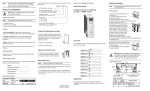
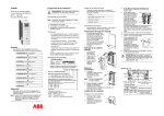
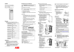
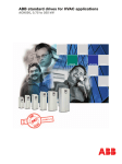
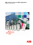
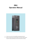
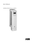
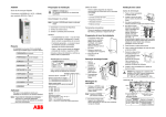
ACS550
Quick Start Guide
ACS550-01 Drives (0.75…160 kW),
IP54 / UL Type 12 Enclosure
Prepare for installation
Collect motor data
WARNING! The ACS550 should ONLY be
installed by a qualified electrician.
PREPARE for installation
PREPARE mounting location
REMOVE the front cover
MOUNT the drive
INSTALL wiring
REINSTALL the cover
APPLY power
START-UP
Application
This guide provides a quick reference for
installations involving: ACS550-01 drives, cable
connections and IP54 / UL type 12 enclosures.
Note: This guide does not provide detailed
installation, safety or operational
instructions. See ACS550 User’s Manual for
complete information.
Install the wiring
Tools required
Screwdrivers, wire stripper, tape measure,
mounting screws or bolts and drill.
• Wiring – Follow local codes for wiring, circuit
protection and EMC requirements.
Refer to User’s Manual and confirm that all
preparations are complete.
Remove the front cover
• Suitable environment – Drive requires heated,
indoor controlled environment that is suitable
for the selected enclosure.
Drive identification
ACS550-01-08A8-4
U1
3~ 380...480 V
I2N/ I2hd 8.8/6.9 A
Serno
PN/Phd 4.0/3.0 kW
*2030700001*
Use the following chart to interpret the type
code found on the drive label.
ACS550-01-08A8-4+B055+…
CHECK installation
• Nominal power ____________________
The drive requires a
smooth, vertical, solid
surface, free from heat and
moisture, with free space for
air flow – 200 mm (8 in)
above and below.
1
1. Mark the mounting points
using the template.
2. Drill the mounting holes.
• Motor compatibility – Motor type, nominal
current, frequency and voltage range must
match drive specifications.
The installation of the ACS550 adjustable
speed AC drive follows the outline below.
• Nominal speed ____________________
General wiring
1. Cut the rubber cable
seals as needed for the
power, motor and control
cables. The conical part
of the seals must face
downwards when
1
inserted in the leadthrough plate holes.
Prepare the mounting location
Check
AC, Standard Drive – 550 series
Construction (region specific)
01 = Setup/parts for IEC install./compliance
U1 = Setup/parts for US install./compliance
Output current rating
See Ratings in User’s Manual for details
Voltage rating
2 = 208…240 V AC
4 = 380…480 V AC
6 = 500…600 V AC
Options
Examples of options:
No specification = IP21 / UL type 1
B055 = IP54 / UL type 12
UL type 12 is not available for type
ACS550-01-290A-4.
0J400 = No control panel
J404 = ACS-CP-C Basic Control Panel
Note: Lift the ACS550 by its metal chassis.
4. Reinstall the rubber plugs.
5. Non-English speaking locations: Attach a
warning sticker in the appropriate language
over the existing warning on the top of the
module.
• Nominal frequency _________________
1. Unpack the drive.
2. Check for any damage.
3. Check the contents against the order / shipping
label.
3. Position the ACS550 and securely tighten in all
four corners.
• Voltage __________________________
• Nominal motor current ______________
Unpack the drive
Note: Lift the ACS550 by its chassis and not by its
cover.
Overview
Collect the following data from the motor
nameplate for later use in the ACS550 startup:
1. If hood is
present:
Remove screws
(2) holding hood
1
in place.
2. If hood is
present: Slide
hood up and off
the cover.
3. Loosen the
captive screws
3
around the edge
of the cover.
4. Remove the
cover.
IP5003
Wiring power
X0002
2
FM
4
Mount the drive
The holes providing for access to the drive
mounting slots require rubber plugs.
1. As required for access,
3
remove the rubber
plugs. Push plugs out
from the back of the
drive.
2. R5 & R6: Align the
1, 4
sheet metal hood (not
5
shown) in front of the
drive’s top mounting
holes. (Attach as part of
next step.)
1. On the input power
5
cable, strip the
sheathing back far
1
2
enough to route
3
3
individual wires.
2. On the motor cable,
strip the sheathing
IP5004
back far enough to
expose the copper wire shield so that the shield
can be twisted into a bundle. Keep the bundle
bundle not longer than five times its width to
minimize noise radiation. – 360° grounding
under the clamp is recommended for the motor
cable to minimize noise radiation. In this case,
remove the sheathing at the cable clamp.
3. Route both cables through the clamps and
tighten the clamps.
4. Connect the bundle created from the motor
cable shield to the GND terminal.
5. Strip and connect the power/motor wires and
the power ground wire to the drive terminals
using the torques given in the table below. See
Power connections below or, for more detail,
see User’s Manual.
Frame size
R1, R2
R3
R4
R5
R6
FM
N·m
1.4
2.5
5.6; PE: 2
15
40; PE: 8
Tightening torque
lb·ft
1
1.8
4; PE 1.5
11
30; PE: 6
System type
R1...R3
R4
R5...R6
EM1 EM3 EM1 EM3 F1 F2
-
IT system
Corner grounded TN
system
-
-
-
Power connections
See table Optional
braking below.
Frame size R1…R4
EM3
EM1
PE
GND
X0033
Power input
(U1, V1, W1)
Power output to motor
(U2, V2, W2)
Frame size R5
Optional braking
Frame size Terminal labels
Brake options
R1, R2
BRK+, BRKBrake resistor
R3…R6
UDC+, UDC• Braking unit
• Chopper and resistor
Wiring the controls
1. Strip control cable
sheathing and twist the
3, 4
copper shield into a
bundle.
2. Route control cable(s)
through clamp(s) and
tighten clamp(s).
3. Connect the ground
2
shield bundle for digital
and analog I/O cables at
X1-1. (Ground only at
the drive end.)
IP5005
4. Strip the individual
control wires and connect to the drive terminals.
Use a tightening torque of 0.4 N·m (0.3 lb·ft). See
Control connections below or, for more detail,
see User’s Manual.
F2
See table Optional
braking below.
X1
GND
PE
X0035
Power output to motor
(U2, V2, W2)
Power input
(U1, V1, W1)
Frame size R6
F2
See table Optional
braking below.
F1
Proper cooling space around the drive.
For IT systems and corner grounded TN systems:
The internal EMC filter is disconnected (see the table
in Wiring power).
Control terminals are wired and tightened as
specified.
19
20
21
22
23
24
25
26
27
RO1C
RO1A
RO1B
RO2C
RO2A
RO2B
RO3C
RO3A
RO3B
Relay output 1
Default operation:
Ready = 19/21 connected
Relay output 2
Default operation:
Running = 22/24 connected
Relay output 3
Default operation:
Fault(-1) =25/27 connected
(Fault => 25/26 connected)
or
Note: Before increasing motor speed, check that
the motor is running in the desired direction.
Motor and driven equipment are ready for start.
Aux. volt. output +24 V DC
Aux. volt. common
Digital input com. for all
Start/Stop: Active = start
Fwd/Rev: Active = rev. dir.
Constant speed sel.2
Constant speed sel.2
Ramp pair: Active = 2nd ramp pair
Not used
J1
ON
Power output to motor
(U2, V2, W2)
The drive is mounted securely.
The input power (mains) terminals, U1, V1, W1, are
connected and tightened as specified.
The input power (mains) fuses are installed.
The motor terminals, U2, V2, W2, are connected and
tightened as specified.
Motor cable is routed away from other cables.
NO power factor compensation capacitors are in the
motor cable.
NO tools or foreign objects (such as drill shavings)
are inside the drive.
NO alternate power source for the motor is
connected – no input voltage is applied to the output
of the drive.
Reinstall the cover
1. Align the cover
and slide it on.
2. Tighten the captive 4
screws around the
edge of the cover.
3. Slide the hood
down over the top
5
of the cover (UL
type 12 only).
6
4. Install the two
screws that attach
the hood (UL type
12 only).
WARNING! The ACS550 will start up
automatically at power up, if the external run
command is on.
1. Apply input power.
When power is applied to the ACS550, the
green LED comes on.
24V
GND
DCOM
DI1
DI2
DI3
DI4
DI5
DI6
1 2
GND
Check
Environment conforms to specifications.
10
11
12
13
14
15
16
17
18
ON
PE
Before applying power, perform the following
checks.
Input power (mains) voltage matches the drive
nominal input voltage.
AI1: 0…10 V
AI2: 0(4)…20 mA
Apply power
Always reinstall the front cover before turning
power on.
Check installation
ABB Standard macro
Signal cable shield (screen)
SCR
AI1
Ext. freq. ref. 1: 0…10 V
AGND Analog input com.
10V
Ref. voltage 10 V DC
AI2
Not used
AGND Analog input com.
AO1
Output freq.: 0…20 mA
AO2
Output current: 0…20 mA
AGND Analog output com.
ON
Power input
(U1, V1, W1)
J1
6. Optional: Add a lock (not supplied) to secure
the control panel window.
WARNING! The maximum voltage for digital
inputs is 30 V.
1
2
3
4
5
6
7
8
9
Note 1. Jumper setting (two switch types possible):
X0013
Note: The control panel window must be closed to
comply with IP54 / UL type 12.
Drive is properly grounded.
Control connections
F1
5. Install the control panel.
Note 2. Code: 0 = open, 1 = connected
DI3 DI4
Output
0
0
Reference through AI1
1
0
CONSTANT SPEED 1 (1202)
0
1
CONSTANT SPEED 2 (1203)
1
1
CONSTANT SPEED 3 (1204)
Start-up
In start-up, enter motor data (collected earlier)
and, if needed, edit parameters that define how
the drive operates and communicates.
Assistant Control Panel
The Start-up Assistant steps through typical
start-up selections, and runs automatically
upon the initial power up. At other times, use
the steps below to run the Start-up Assistant.
1. Use the MENU key to
access the Main menu.
2. Select ASSISTANTS.
3. Select Start-up Assistant.
4. Follow the screen
instructions to configure the
system.
49.1Hz
400RPM
LOC
LOC
49.RPM
1 Hz
1200
12.40.
A5 A
405
10.dm3/s
7 %
DIR
DIR
12:45
00:00
Note: For common parameters and menu items,
use the Help key ? to display
descriptions.
If you encounter alarms or faults,
use the Help key or refer to chapter
Diagnostics in User’s Manual.
3
Basic Control Panel
FM
1
2
MENU
MENU
The Basic Control Panel does not
include the Start-up Assistant. Refer to
section How to start up the drive in
User’s Manual and manually enter any
parameter changes desired.
Code: 3AUA0000005428 REV E / EN
Effective: 2009-07-07
Supersedes: 2007-04-16
WARNING! To disconnect the internal EMC
filter, remove the screws marked with “-”, or
replace the screws marked with “ ” with the
provided polyamide screws, depending on
the frame size.