1
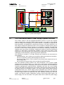
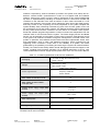
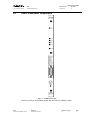
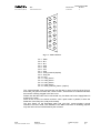
PRELIMINARY
Document type:
User's Manual (MUT)
Title:
EASY4000 Interlock
Revision date:
05/07/2007
Revision:
0
2. EASY4000 Interlock
2.1
Interlock at board level
The “Interlock board” purpose is to provide each of the 4 interlock lines (see A4601 and
A4602 manuals) with one optocoupler diode that has to be driven continuously in order to
avoid the “interlock condition”; this can be done by providing on the 2 DB15 pins of each
interlock line, directly the anode and cathode of the Optoisolator diode with a series
resistor. The current on the external lines is lower than 10mA and the voltage required is
24V.
2.2
Interlock at crate level
This board implements a presence control, that is: if the board is removed from the crate,
all the PSUs in that crate are switched off, with the OPC accessed parameter “MainPwS”
set to “FAIL” (it is normally “OK”).
The “Interlock board” foresees an “option”, to be enabled via an internal dip switch (the
only one in the board) ; it is also available a “Crate interlock” through the same DB15
female connector used for the 4 backplane interlock lines on the A4600 Interlock Board
front panel. If the dip switch “enables” the “Crate Interlock”, then the driving mode that
has to be used on the DB15 pins is equal to those of the standard PSU interlock inputs.
2.3
Reset
A connector and a push button to drive the Reset line of the crate are available on the
front panel. The logic is “Normally open”: whether the button is pressed or the Lemo 00
connector pins becomes short circuited, there is the Reset event in all the PSM.
NPO:
00110/06:A4600.MUTx/00
Filename:
A4600_REV0.DOC
Number of pages:
10
Page:
8