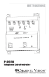
1
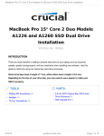
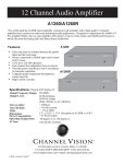
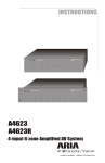
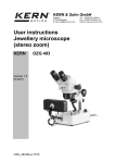
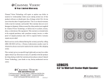
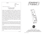
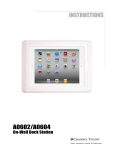
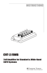
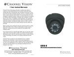
Aria
Aria
12 CHANNEL AMPLIFIER
A1260
By Channel Vision
12 CHANNEL AMPLIFIER
A1260
By Channel Vision
A1260
A1260R
12 Channel Audio Amplifier
By
2012
A1260 Rear Panel
The A1260 is a 12-channel (6-zone) audio amplifier designed for whole house
music applications. It can supply up to six pairs of speakers with enough power to
ensure high-quality audio in every listening area. The rack mount version (model
A1260R) is available for installations in 19” equipment racks.
The amplifier is organized into 6 stereo pairs. Each pair may be driven with a
system wide signal, or its own input.
Each of the 12 channels will turn on automatically at the presence of an audio
signal and will turn off when the audio signal is gone.
The A1260 is available in a rack mount version, A1260R.
The A1260 is intended to be constantly on. Power consumption during times of no
audio is less than 30 watts.
Features:
!
Audio-sensing inputs
!
Input selector allows either global or zone input
!
Low power consumption when no audio is present
!
Cost effective and easy to install
Dimensions:
Note: these dimension do not include the rubber feet on the bottom of the unit or
the connectors which protrude from the rear of the unit. The rubber feet will add
0.25 inches to the height and the connectors (without wires attached) will add 0.5
inches to the depth.
A1260
14.5”
Aria
12 CHANNEL AMPLIFIER
A1260
By Channel Vision
5.25”
16.75”
A1260R
5.25”
14.5”
Aria
12 CHANNEL AMPLIFIER
A1260
By Channel Vision
19.0”
2
IMPORTANT SAFETY INSTRUCTIONS
1. Read these instructions.
2. Keep these instructions for future reference
3. Heed all warnings.
4. Follow all instructions.
5. Do not use this device near water.
6. Clean only with a dry cloth.
7 Do not block any ventilation openings. Install in accordance with these
instructions.
8. Do not install near any heat sources such as radiators, heat registers,
stoves, or other apparatus (including amplifiers) that produce heat. When
installing multiple amplifiers in the same rack, provide space for air
circulation above and below each unit.
9. Do not defeat the safety purpose of the polarized or grounding-type plug.
A polarized plug, has two blades with one wider than the other. A grounding
type plug has two blades and a third grounding prong. the wide blade or the
third prong are provided fro your safety. If the provided plug does not fit
!
into your outlet, consult an electrician for replacement of the obsolete
!
!
outlet..
!
10. Protect the power cord from being walked on or pinched particularly at
plugs, convenience receptacles, and the point where the exit from the
apparatus.
11. Only use attachments/accessories specified by Channel Vision.
12. Use only with the cart, stand, tripod, bracket, or table specified by the
manufacturer, or sold with the apparatus. When a cart is used, use caution
when moving the cart/apparatus combination to avoid injury from tip-over.
13. Unplug this apparatus during lightning storms or when unused for long
periods of time.
14. Refer all servicing to qualified service personnel. Servicing is required
when the apparatus has been damaged in any way, such as power supply
cord or plug is damaged, liquid has been spilled or objects have fallen into
the apparatus, the apparatus has been exposed to rain or moisture, does
not operate normally, or has been dropped.
CAUTION: To reduce the risk of electric shock,
CAUTION
15.
do not remove the cover (or back), no userRISK OF ELECTRIC SHOCK
DO NOT OPEN
!
serviceable parts inside, refer servicing to qualified
service personnel.
The lightning flash with an arrowhead symbol within an equilateral
triangle is intended to alert the user to the presence of uninsulated
dangerous voltage within the product’s enclosure that may be of
sufficient magnitude to constitute a risk of electric shock to persons.
!
The exclamation point within an equilateral triangle is intended to
alert the user to the presence of important operating and
maintenance accompanying the appliance.
16. Apparatus shall not be exposed to dripping or splashing and objects
filled with liquids, such as vases, shall not be placed on the apparatus.
3
A1260 Rear Panel
10A 120V
5A 240V
Slow Blow
CAUTION
Input Voltage
12
0
24
120V ~ 60 Hz
240V ~ 50 Hz
1000 W
Global
IN
6
SPKR
IN
5
SPKR
R
Local
IN
4
SPKR
R
Local
L
Global
IN
3
Local
IN
2
SPKR
R
Local
L
Global
Model A1260 12 Channel Amplifier
SPKR
R
L
Global
Aria by Channel Vision
Warning:
To prevent fire or shock hazard do not
expose this unit to rain or moisture.
!
RISK OF ELECTRIC SHOCK
DO NOT OPEN
0
Local
L
Global
IN
1
SPKR
R
R
Local
L
Global
L
Global
XXXX
USE CLASS 2 WIRING FOR SPEAKER OUTPUTS
Made in China
Ÿ
Each zone may be switched between the global input and the local input.
Ÿ
Sources connected to Global input can be heard in all 6 zones.
Ÿ
110-120 or 220-240 operation
Ÿ
Each channel has independent turn-on sensors.
Ÿ
Torroidal power transformer with 4 secondaries to maximize separation.
Ÿ
Computer-grade components throughout to ensure long-life.
Ÿ
Turn on time <500msec Turn off time ~ 30-100 seconds
Ÿ
Ideal companion to A4603 Matrix A/V controller
4
Creating a System
The A1260 provides plenty of power to create a great whole-house system,
but it does not provide source selection and volume control. Therefore, a
matrix controller, such as the A4603, is needed to unlock the full potential of
the A1260.
Aria
By Channel Vision
4x6 Matrix Switcher
A4600
Aria
4x6 Matrix Switcher
A4600
By Channel Vision
Ÿ
Ÿ
Ÿ
The A4603/A4603R... is a 4 input 6 output matrix A/V controller designed for
whole-house audio systems.
Ÿ
Ÿ
The unit is organized into 4 audio/video inputs and 6 audio/video outputs.
The A4603 is intended to be used with a multichannel audio amplifier, such
Ÿ
as the A1260.
Ÿ
Any of the 4 source inputs can be selected and routed to any of the 6
Ÿ
outputs (or zones) independent of the other zones through the use of an IR
repeating keypad (such as the A0127- Sold separately).
The A4603R is equipped with a rack mount faceplate to allow installations in
a standard 19” equipment rack.
Control of the A4603... is accomplished
through the use of an IR repeating device,
such as the A0127 keypad. The A0127
already contains the IR codes necessary to
operate the A4603, but you may also use a
standard IR receiver such as the IR-2400 or a
3rd party keypad. When using a simple IR
receiver, you will need to program a learning
remote control with the IR codes for the
A4603. These codes can be downloaded
from www.channelvision.com, or learned from
an A0127.
A0127
Vid 1
Vid 2
Vid 3
Vol
+
Vol
-
Vid 4
Pwr
Mute
5
Sample Wiring Diagram:
Using the A4603 & A1260 together
DVD player
CD player
Attach IR emitters to the face
of the components to enable IR control.
Channel Vision
Sig
Gnd
+V
A4601
Tested To Comply
With FCC Standards
6
FOR HOME OR OFFICE USE
Control
5
4
3
2
Video
R-Audio-L
Control
Control
1A/250V
1
FUSE
IR Emitters
Power
Input Voltage
115
R-Audio-L
Video
R-Audio-L
5
Video In
Termination
Video
3
6
1
4
OUTPUTS
R-Audio-L
Hi-Z
75
1234
2
OUTPUTS
R-Audio-L
Video
OUTPUTS
Video
3
1
4
2
230 / 115 VAC
50 / 60 Hz
INPUTS
A4603 Rear Panel
10A 120V
5A 240V
Slow Blow
CAUTION
Input Voltage
12
0
24
120V ~ 60 Hz
240V ~ 50 Hz
1000 W
Global
IN
6
SPKR
IN
5
SPKR
R
Local
4
IN
SPKR
R
IN
3
Local
L
Global
IN
2
SPKR
R
Local
L
Global
Model A1260 12 Channel Amplifier
SPKR
R
Local
L
Global
Aria by Channel Vision
Warning:
To prevent fire or shock hazard do not
expose this unit to rain or moisture.
!
RISK OF ELECTRIC SHOCK
DO NOT OPEN
0
Local
L
Global
IN
1
SPKR
R
R
Local
L
Global
L
Global
XXXX
USE CLASS 2 WIRING FOR SPEAKER OUTPUTS
Made in China
A1260 Rear Panel
CAT5
Vid 1
Vid 2
Vid 3
Vol
+
Vol
-
Room 6
Vid 4
Ÿ
IR signals detected by the A0127 keypad
Mute
will be repeated back to the A4603.
This allows control of the input sources.
3
SI
VI
1
2
PO
W
S
N
6
4
VOL
ZO
PO N E
WE
R
MUT
E
MO
A0 DE
50 L
1
C
E
H
C
R
U
AN
O
LE
ER
O
N
TM
Pwr
Changing Fuses
*NOTE: Refer all servicing to qualified service personnel.
The A1260 contains 5 fuses. In certain situations, such as a surge or improper
load place on the amplifier, these fuses maybe need to be changed.
One fuse is installed in the rear of the unit, and can be removed with a flat
head screwdriver. The rating and size of this fuse is:
10A/250V 5x20mm (slo-blow)
GJ3
L
NA
-SIG
GND
GND-POWER
Channel Vision
351-002B.PCB
Mecca ground
GJ9
Fuse pin 1
GJ4
Ÿ
Four fuses are installed in the inside of the unit, and can be replaced by
removing the cover off the A1260.
The rating and sizes of these fuses are:
7A/250V 3AB ceramic 6.35mm x 31.75mm (slo-blow)
7
1
Channel Vision Technology will repair or replace any defect in material or
workmanship which occurs during normal use of this product with new or rebuilt
parts, free of charge in the USA, for one year from the date of original purchase. This
is a no hassle warranty with no mail in warranty card needed. This warranty does
not cover damages in shipment, failures caused by other products not supplied by
Channel Vision Technology, or failures due to accident, misuse, abuse, or alteration
of the equipment. This warranty is extended only to the original purchaser, when
purchased through an authorized reseller. A purchase receipt, invoice, or other
proof of original purchase date will be required before warranty repairs are
provided.
Mail in service can be obtained during the warranty period by calling (800) 840-0288
toll free. A Return Authorization number must be obtained in advance and can be
marked on the outside of the shipping carton.
This warranty gives you specific legal rights and you may have other rights (which
vary from state to state). If a problem with this product develops during or after the
warranty period, please contact Channel Vision Technology, your dealer or any
factory-authorized service center.
Channel Vision products are not intended for use in medical, lifesaving, life
sustaining or critical environment applications. Channel Vision customers using or
selling Channel Vision products for use in such applications do so at their own risk
and agree to fully indemnify Channel Vision for any damages resulting from such
improper use or sale.
Specifications: (typical @25º C)
Output Frequency Range:
Output Load Range:
Output Level:
Audio sense on delay:
Audio sense off delay:
THD:
Power Consumption:
Operating Temperature:
AC fuse:
20-20kHz
8-16 ohms
60 W/ch 8ohms (2 ch. driven)
< 500msec
~ 30-100 seconds
< 0.05%
< 30 W (no input)
-10ºC to +35ºC
10A Slo-blo 5x20mm
Specifications subject to change without notice.
www.channelvision.com
234 Fischer Avenue, Costa Mesa, California 92626 USA
(714)424-6500 (800)840-0288 (714)424-6510 fax
email: [email protected]
500-009 rev F