1
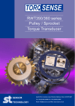
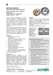
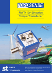
TORQ SENSE ® RWT450/460 series Pulley / Sprocket Torque Transducer SENSOR Apollo Park, Ironstone Lane, Wroxton, Banbury, Oxon, UK OX15 6AY Tel: +44 (0)1869 238400 Fax: +44 (0)1869 238401 TECHNOLOGY Email: [email protected] Web: www.sensors.co.uk SENSOR TECHNOLOGY TORQ SENSE ® Digital RWT450/460 series Torque Transducer TorqSense Digital RWT450/460 series pulley / sprocket transducers with seperate electronics now offer cost effective, non-contact digital rotary torque measurement, using Surface Acoustic Wave technology, suitable for torque monitoring and process control on any belt / chain driven machinery. TorqSense transducers and their technology are particularly appropriate for OEM applications. The new TorqSense RWT450/460 torque sensors replace the RWT350/360 series and feature all new electronics that have produced significant performance gains in resolution, frequency response, reduced sensor current consumption and faster digital data throughput. Transducer overload has also been increased to 300%. Benefits Direct replacement for standard pulley/sprocket Low inertia – High Speed capability because electronics are not fixed onto shaft Non contact/brushless measurement High bandwidth 10kHz 300% safe mechanical overload High accuracy and resolution Excellent noise immunity Separate digital electronics Operates both statically and dynamically - clockwise/anti-clockwise Any full scale torque can be specified within standard range: 50Nm through to 10,000Nm Lifetime warranty Consult factory for ranges greater than 10KNm High speeds available on request TorqSense RWT450 series transducers offer: Fixed voltage or current analog outputs (one for torque and the other for speed or power) for interfacing with analog instrumentation BIT Self-diagnostics for letting the manufacturer know that the transducer’s torque, speed ratings and calibration due date have not been exceeded. Simple ‘Sensor status’ output pin Sensors to monitor shaft temperature for better compensation and accuracy Whereas, TorqSense RWT460 series transducers offer: Digital outputs, such as RS232, CANbus and USB, for interfacing with modern instrumentation and laptops Digital input for configuring transducer via PC 2 x user selectable voltage or current analog outputs (one for torque and the other for speed, power or peak torque) for interfacing with analog instrumentation Transducer configuration software to allow user to changes transducer variables BIT Self-diagnostics for letting users know data is trustworthy, that the transducer’s torque, speed ratings and calibration due date have not been exceeded Simple ‘Sensor status’ output pin Sensors to monitor shaft temperature for better compensation and accuracy Ability to connect up to 10 transducers using USB TORQ VIEW Software TorqView is an easy to use advanced torque monitoring software, available to assist data recording and instrumentation displays that interface with Windows based PCs. Features include: 3 types of display, text files compatible with Matlab and Excel and Real time chart plotting. See TorqView datasheet for more details. Technology TorqSense patented technology is the measurement of the resonant frequency change in 'frequency dependent' Surface Acoustic Wave (SAW) devices, caused when strain is applied. The signal is coupled via a non-contact RF rotating couple from the shaft to a fixed pick-up. A separate electronics module enables the resonant frequencies to be measured and offer user selectable features, digital outputs and diagnostics. SAW devices are not affected by magnetic fields. US Patents: US5585571, US6478584. LabView VIs are available for users to design their own process control applications. DLLs are also available for users to write their own custom software. RWT3243R RWT450/460 Series Torque Transducers - Data Specification Parameter Condition PRELIMINARY Data Units RWT450/460 Torque measurement system Measurement method Strain Dependent Surface Acoustic Wave Resonators (interrogated by an incremental electronic scanning method) (See Notes 1 Torque range From 50 – 10,000 Nm & 2 below) [lbf.in] [From 500 – 100,000] Rotation speed/angle of rotation measurement system Measurement method Magnetic pick-off sensor Direct output signal Pulse output direct from opto switch (TTL, 5V square wave), output is independent of any analog or digital processing. Digital Processing Processing Method Update rate for analog and digital outputs Techniques 3 Pulse/Rev Magnetic Speed Sensor Mode 1 (Slow Method) 1 Hz Frequency Count (See Note 3) Rotational speed (max) Temperature Measurement method Temperature accuracy Reference temperature, TRT Operating range, ∆TO Storage range, ∆TS Temperature drift (FS) Max Specifications Linearity Hysteresis Resolution Repeatability RWT450 Series Transducers ONLY Frequency response Accuracy 200C, SM (See Consult factory IR temperature sensor monitoring actual shaft temperature 1 20 Note 4) RWT460 Series Transducers ONLY Frequency response Accuracy 200C, SM (See Note 4) 10,000 1 RPM 4500 0.7 2250 0.5 1125 0.5 0 C C 0 0 -10 to +50 -20 to +70 0.05 C C %FS/0C 0.5 <0.1 0.02 0.1 %FS %FS %FS %FS 101 0.5 Hz %FS 562 0.5 0 281 0.5 140 0.5 70 0.5 (See Note 5) Digital averaging 1 2 4 8 16 32 64 128 Analog output Output voltages Options available: 1 / 5 / 10 / Unipolar (RWT450 Series default setting is 5Vdc) (Torque/Speed/Power) (RWT460 Series output voltages are user selectable) Load impedance 1 Output currents Options available: 4-20 / 0-20 / 128 (Torque/Speed/Power) (RWT460 Series output currents are user selectable) 4-20mA Loop resistance Should not exceed 400 Digital output (RWT460 Series Transducers ONLY) Output type RS232 (Standard), USB 2.0 full speed 12 Mbps (optional), CANbus (optional) Sampling rate 1.62 Power supply Nominal voltage, VS 12 to 32 (max) Current consumption, IS 230 (max) Power consumption, WS 3 Allowed residual ripple of 500 supply voltage, Vripple (above nominal supply voltage) Electromagnetic compatibility EMC compatibility EN 61326:2006 Note 1. Note 2. Note 3. Note 4. Note 5. Any torque/FSD is possible between ranges – please specify max rated torque. Max rated torque should not be exceeded. Please consult factory for applications requiring rotational speeds that exceed maximum figures given. Transducers fitted for IP65 will have running speeds considerably reduced, increased drag torque and accuracy can be affected. SM – Static Mode. Dynamic values will depend upon user application and has to be adjusted accordingly. Digital averaging can be configured by user to optimise accuracy/frequency response for specific user applications. Digital averaging default setting is N=16. For details see User Manual. Data parameters measured at +20°C Sensor Technology Ltd reserves the right to change specification and dimensions without notice. © Sensor Technology Ltd 2012 RWT3437R (Rev2) Hz %FS N Vdc KΩ mA Ω ksps V mA W mVp-p RWT450/460 Series Torque Transducers Dimensions (5KNm) (Please consult factory for other sizes) RWT450/460 Series Electronics Module Data parameters measured at +20°C Sensor Technology Ltd reserves the right to change specification and dimensions without notice. © Sensor Technology Ltd 2012 RWT3437R (Rev2) RWT450/460 Series Torque Transducers - Standard Range ● – Standard feature ◊ – Optional feature Torque, Speed, Power Outputs Torque only Torque & Speed (Low Resolution) Torque & Speed (High Resolution) Torque & Power Torque & Speed (Low Resolution) or Power Torque & Speed (High Resolution) or Power Standard features Voltage Output ±5v FSD Voltage Output ±1v to ±10v FSD and Unipolar RS232 Output Torque Averaging Torque Peak Self Diagnostics Internal Temperature Reading Deep grooved shielded bearings with oil lubrication Ingress Protection (IP) 54 Link Cable (1.5m) Optional features Voltage Output ±1v FSD Voltage Output ±10v FSD Unipolar voltages Current Output 0-20mA Current Output 4-20mA Current Output 12mA±8mA RWT450/460 Series RWT450 RWT460 450 460 (See Note 7 below) Ingress Protection (IP) 65 connectors in lead b/w head & electronics Cavity ‘D’ connectors in lead b/w head & electronics Link Cable (>1.5m) Remarks Specify RPM/FSD (3 pulses / rev) Not yet available (360 pulses / rev) Specify Power/FSD User self selectable (3 pulses / rev) Not yet available (360 pulses / rev) 451 452 453 461 462 B ● User self selectable ● ● ● ● ● ● ● ● ● ● ● ● From sensor head to electronics module A C U D E V ◊ ◊ ◊ ◊ ◊ ◊ Current Output 0-20mA, 4-20mA & 12mA±8mA USB2.0 full speed 12 Mbps Digital output CANbus output High Speed Bearings Sealed Bearings Ingress Protection (IP) 65 - for sensor and electronics Option Code ◊ F ◊ ◊ ◊ ◊ ◊ ◊ G H J S ◊ ◊ L ◊ ◊ ◊ ◊ ◊ ◊ In place of Option B In place of Option B User to specify In place of Options A,B & C In place of Options A,B & C In place of Options A,B & C Current output is user selectable and in place of Voltage output. However user can reselect a Voltage output, if required. (Note 6) In place of RS232 Consult factory for maximum speed allowances M N R Consult factory for length Note 6. 2 x analog channels available. Default settings are Channel 1 (voltage/current) – torque. Channel 2 (voltage/current) – speed or power, if ordered. Note 7. Transducers fitted for IP65 will have running speeds considerably reduced, increased drag torque and accuracy can be affected. Data parameters measured at +20°C Sensor Technology Ltd reserves the right to change specification and dimensions without notice. © Sensor Technology Ltd 2012 RWT3437R (Rev2) RWT450/460 Series Torque Transducers – Connector and Lead Options Connectors & Leads Analog Connector 12 Pin Lumberg (female) RWT450/460 Series RWT450 RWT460 ◊ Digital Connector 12 Pin Lumberg (male) Analog Lead (Length 2.5m) 12 Pin Lumberg (female) to 15 way ‘D’ type connector (female) Digital Lead (Length 2.5m) 12 Pin Lumberg (male) to 15 way ‘D’ type connector (male) ◊ Option Code ACC 1 ◊ ACC 2 ◊ ACC 3 For connecting RWT to user’s system via 15 pin ‘D’ connector ◊ ACC 4 For connecting RWT to user’s system via 15 pin ‘D’ connector ◊ ACC 5 ◊ ACC 6 ◊ ACC 8 ◊ ACC 9 Digital Lead Adapter (Length 1m) 15 Way ‘D’ type (female) to RS232, USB and Power Connectors Digital Lead Adapter (Length 1m) 15 Way ‘D’ type (female) to CANbus and Power Connectors Digital Lead Adapter (Length 1m) 15 Way ‘D’ type (female) to CANbus, USB and Power Connectors For user to self wire ◊ Digital Lead Adapter (Length 1m) 15 Way ‘D’ type (female) to RS232 and Power Connectors Remarks/Purpose For user to self wire For connecting RWT to PC via RS232 [Also needs Digital Lead (ACC4) to connect to RWT] For connecting RWT to PC via USB (Option G) or RS232 [Also needs Digital Lead (ACC4) to connect to RWT] For connecting RWT to PC via CANbus (Option H) [Also needs Digital Lead (ACC4) to connect to RWT] For connecting RWT to PC via USB (Option G) or CANbus (Option H) [Also needs Digital Lead (ACC4) to connect to RWT] RWT450/460 Series Torque Transducers – Additional related products Code ETD PSU 1 SBU 2 TV Transducer Display ETD AC Mains Adapter Power Supply Transducer Signal Breakout Unit TorqView Remarks/Purpose Display readout For providing 12-32Vdc Torque Monitoring Software ACC 3&4 12 Pin Lumberg 15 W ay D Type ACC 5 or 8 RS232 (ACC 5) / CANbus (ACC 8) 15 W ay D Type (connects to ACC4) Power ACC 6 or 9 RS232 (ACC 5) / CANbus (ACC 9) USB 15 W ay D Type (connects to ACC4) Power Data parameters measured at +20°C Sensor Technology Ltd reserves the right to change specification and dimensions without notice. © Sensor Technology Ltd 2012 RWT3437R (Rev2) When you order a Torque Transducer please note that any torque/FSD is possible between ranges – please specify rated torque and options using the following format: For example: RWT 451 - 100Nm - CL Your transducer requirement: RWT Max speed (if applicable) A ‘basic’ transducer with torque and speed outputs, rated and calibrated to 100Nm FSD, ±10v and IP65 protection. RPM Connector & Lead options (if applicable) See over Additional related products (if applicable) See over Glossary of terms and definitions used in this datasheet Surface Acoustic Wave (SAW) - An acoustic wave travelling along the surface of a material having some elasticity, with amplitude that typically decays exponentially with the depth of the substrate. Strain dependent SAW resonators – A type of elastic SAW device, which changes its resonant properties when it is subjected to axial strain/compression. TorqSense uses this principle, which is protected by a number of patents. Incremental Electronic Scan (IES) – The most successful and precise method for interrogating strain dependent SAW resonators. The IES interrogation method uses a processor controlled frequency synthesiser to excite the SAW resonators over a defined range of frequencies and measure the reflected signal. TorqSense uses this patented method. Resolution of the IES method - The minimum measurable number corresponding to the stress/strain sensitive resonance point of the SAW resonator. The value is limited by following the factors: frequency resolution of the synthesiser, which is 1000 times greater then overall resolution of the system. relationship between frequency response and resolution. Increments of the resolution will proportionally decrease the system’s frequency response. TorqSense systems are optimised for the best performance that suits most applications. However, on the RWT460 series models customers do have the capability to adjust the system performance. Frequency response of the IES method – The measure of the TorqSense system's response at the output to a signal of varying frequency at its input. The frequency response is typically characterised by the magnitude of the system's response, measured in dB. There are two ways of characterising the system’s frequency response: 0.1dB frequency range, where the output magnitude of the signal is different to the input magnitude of the signal by not more then 0.1dB (practically absolutely identical). 3dB frequency range, where the output magnitude of the signal is 0.707 of the input signal. This is a common standard for most applications, unless it specifically says otherwise. This standard is also used to characterise the TorqSense system’s frequency response. Accuracy - The degree of conformity of a measured or calculated quantity, which will show the same or similar results. Accuracy of the overall TorqSense system is limited by the combined error of several factors such as linearity, hysteresis, temperature drifts and other parameters affecting measurements. If errors in the system are known or can be estimated, an overall error or uncertainty of measurement can be calculated. Digital averaging – The application of algorithms to reduce white noise. In any electronic system, electronic white noise is mixed with the signal and this noise usually limits the accuracy. To reduce the influence of white noise and increase the accuracy of the system different averaging algorithms can be applied. In the TorqSense system a flying digital averaging technique is applied to reduce the white noise commensurate with the level of accuracy required. However, as any averaging algorithm works as a low pass filter, the more averaging that is applied the lower the frequency response. Therefore, each Torqsense system should be optimised to the customer’s requirements by choosing the right combination of accuracy/frequency response. Please see relevant part of the Datasheet and User Manual. Data parameters measured at +20°C Sensor Technology Ltd reserves the right to change specification and dimensions without notice. © Sensor Technology Ltd 2012 RWT3437R (Rev2)